JP2010011348A - Distortion compensation circuit and distortion compensation method - Google Patents
Distortion compensation circuit and distortion compensation method Download PDFInfo
- Publication number
- JP2010011348A JP2010011348A JP2008171169A JP2008171169A JP2010011348A JP 2010011348 A JP2010011348 A JP 2010011348A JP 2008171169 A JP2008171169 A JP 2008171169A JP 2008171169 A JP2008171169 A JP 2008171169A JP 2010011348 A JP2010011348 A JP 2010011348A
- Authority
- JP
- Japan
- Prior art keywords
- model
- distortion compensation
- order
- amplifier
- distortion
- Prior art date
- Legal status (The legal status is an assumption and is not a legal conclusion. Google has not performed a legal analysis and makes no representation as to the accuracy of the status listed.)
- Granted
Links
Images
Landscapes
- Amplifiers (AREA)
Abstract
Description
本発明は、例えば無線送受信機に用いられる高出力増幅器の非線形特性を補償する機能を備えた歪補償回路及びその歪補償方法に関する。 The present invention relates to a distortion compensation circuit having a function of compensating for nonlinear characteristics of a high-power amplifier used in, for example, a radio transceiver, and a distortion compensation method thereof.
一般的に、高出力増幅器(HPA: High Power Amplifier)は、効率特性を優先するが故に、入出力特性の線形性が低い。従って、このような増幅器を用いて電力を増幅すると、入出力特性の歪により、所望の出力が得られない場合がある。そこで、このような歪を補償するための歪補償方式として、増幅器の入力信号に対して、増幅器の歪特性とは逆の、逆歪特性をデジタル信号処理により生成して増幅器の入力に付加するDPD(Digital Pre-Distortion)処理を施すことにより、所望の増幅器出力を得る手法が提案されている(例えば、非特許文献1参照。)。 In general, a high power amplifier (HPA) has low linearity of input / output characteristics because priority is given to efficiency characteristics. Therefore, when power is amplified using such an amplifier, a desired output may not be obtained due to distortion of input / output characteristics. Therefore, as a distortion compensation method for compensating such distortion, a reverse distortion characteristic opposite to the distortion characteristic of the amplifier is generated by digital signal processing for the input signal of the amplifier and added to the input of the amplifier. A technique for obtaining a desired amplifier output by performing DPD (Digital Pre-Distortion) processing has been proposed (for example, see Non-Patent Document 1).
また、広帯域信号を増幅する高出力増幅器に対して精度の高いDPD処理を施すべく、多項式で表される歪補償を行うことが提案されている(例えば、特許文献1参照。)。 In addition, it has been proposed to perform distortion compensation represented by a polynomial in order to perform highly accurate DPD processing on a high-power amplifier that amplifies a broadband signal (see, for example, Patent Document 1).
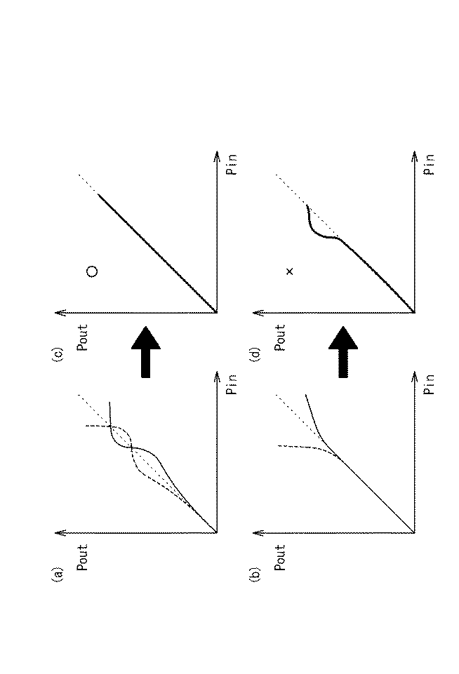
しかしながら、逆歪特性が正しく推定されない場合もあり、その場合には、増幅器の非線形特性を助長する結果となる。図5は、増幅器の入出力特性の2例を示すグラフであり、横軸は入力信号振幅を、縦軸は出力信号振幅を、それぞれ示している。(a)に示す特性は形状が複雑で非線形性が大きく、一方、(b)に示す特性は形状が単純で非線形性が小さい。なお、点線は理想的な直線状の特性を示す。(a)、(b)の特性について、所定次数のべき級数の多項式でモデルの推定を行い、その逆モデルを求めると、図6の(a)、(b)に示す破線のようになる。実線は、図5の(a)、(b)と同一の入出力特性を示す。 However, the reverse distortion characteristics may not be estimated correctly, which results in promoting the nonlinear characteristics of the amplifier. FIG. 5 is a graph showing two examples of input / output characteristics of the amplifier, in which the horizontal axis indicates the input signal amplitude and the vertical axis indicates the output signal amplitude. The characteristic shown in (a) has a complicated shape and a large nonlinearity, while the characteristic shown in (b) has a simple shape and a small nonlinearity. The dotted line shows ideal linear characteristics. With respect to the characteristics of (a) and (b), when a model is estimated with a power series polynomial of a predetermined order and the inverse model is obtained, the result is as shown by broken lines in FIGS. 6 (a) and 6 (b). The solid line shows the same input / output characteristics as those shown in FIGS.
図6の(a)の場合には、入出力特性の歪を補償するに適切な逆モデルが与えられ、その結果、(c)に示すように歪が取り除かれた直線性の高い入出力特性が得られる。ところが、図6の(b)の場合には、逆モデルが不適切となり、過剰な補償を行う。その結果、(d)に示すように、点線の反対側に歪が出る。このような原因は、単純な形状の歪を、高次多項式によって過剰補償することにあると考えられる。このような過剰補償への着眼と、その解決策は、未だ提案されていない。 In the case of FIG. 6A, an inverse model suitable for compensating the distortion of the input / output characteristics is given, and as a result, the input / output characteristics with high linearity from which the distortion is removed as shown in FIG. Is obtained. However, in the case of FIG. 6B, the inverse model becomes inappropriate and excessive compensation is performed. As a result, as shown in (d), distortion appears on the opposite side of the dotted line. This is considered to be due to overcompensation of distortion of a simple shape by a high-order polynomial. A focus on such overcompensation and solutions have not yet been proposed.
かかる従来の課題に鑑み、本発明は、過剰補償を防止する歪補償回路及び歪補償方法を提供することを目的とする。 In view of such a conventional problem, an object of the present invention is to provide a distortion compensation circuit and a distortion compensation method that prevent overcompensation.
本発明は、増幅器の出力信号を入力信号のn次べき級数の多項式の形で表したモデルを推定するモデル推定部と、前記モデルに対する逆モデルを前記入力信号に付加することにより前記増幅器の入出力特性の歪を打ち消す歪補償を行う歪補償部とを備えた歪補償回路であって、前記モデル推定部は、前記多項式における各次の係数が、次数が大きいほど小さいという規則性を維持しているか否かに基づいて、nの値を増減する機能を有するものである。 The present invention provides a model estimation unit that estimates a model in which an output signal of an amplifier is expressed in the form of a polynomial of an n-th power series of the input signal, and an inverse model for the model is added to the input signal to add the input of the amplifier. A distortion compensation circuit that performs distortion compensation that cancels distortion of output characteristics, wherein the model estimation unit maintains a regularity that each order coefficient in the polynomial is smaller as the degree is larger. It has a function to increase or decrease the value of n based on whether or not it is present.
上記のように構成された歪補償回路では、多項式の最大次数であるnを固定値とせず、係数の規則性に着目してモデルの適否を判定し、適切なモデルとなるように増減することができる。特に、過剰補償になる場合には最大次数を下げることができる。 In the distortion compensation circuit configured as described above, n that is the maximum degree of the polynomial is not set to a fixed value, and the suitability of the model is determined by paying attention to the regularity of the coefficient, and is increased or decreased so as to become an appropriate model. Can do. In particular, the maximum order can be lowered in the case of overcompensation.
上記歪補償回路において、規則性に反する係数が出現した場合、モデル推定部は、次数を1減少させてモデルを推定するようにしてもよい。
この場合、過剰補償になる直前の次数で、モデルの推定を行うことができる。
In the distortion compensation circuit, when a coefficient contrary to regularity appears, the model estimation unit may reduce the order by 1 and estimate the model.
In this case, the model can be estimated with the order immediately before overcompensation.
また、上記歪補償回路において、1から順に各次の係数が前記規則性を維持し、かつ、モデルと実際の出力信号との誤差が所定値以内となったときの当該次数を、モデル推定部は、nの値とすることができる。
この場合、規則性の維持によって過剰補償を排除し得る範囲内で、正確なモデルを推定することができる。
Further, in the distortion compensation circuit, each order coefficient in order from 1 maintains the regularity, and the order when the error between the model and the actual output signal is within a predetermined value is calculated as a model estimation unit. Can be the value of n.
In this case, an accurate model can be estimated within a range in which overcompensation can be eliminated by maintaining regularity.
一方、本発明は、増幅器の出力信号を入力信号のn次べき級数の多項式の形で表したモデルを推定し、前記モデルに対する逆モデルを前記入力信号に付加することにより前記増幅器の入出力特性の歪を打ち消す歪補償を行う歪補償方法であって、前記多項式における各次の係数が、次数が大きいほど小さいという規則性を維持しているか否かに基づいてnの値を増減し、1から順に各次の係数が前記規則性を維持し、かつ、前記モデルと実際の前記出力信号との誤差が所定値以内となったときの当該次数を前記nの値とするものである。 On the other hand, the present invention estimates a model representing the output signal of the amplifier in the form of a polynomial of the nth power series of the input signal, and adds an inverse model to the input signal to the input / output characteristics of the amplifier. A distortion compensation method for performing distortion compensation that cancels out the distortion of the equation, wherein the value of n is increased or decreased based on whether or not each order coefficient in the polynomial maintains the regularity that the degree is smaller as the degree is larger. In this order, each order coefficient maintains the regularity, and the order when the error between the model and the actual output signal is within a predetermined value is the value of n.
上記のような歪補償方法によれば、多項式の最大次数であるnを固定値とせず、係数の規則性に着目してモデルの適否を判定し、適切なモデルとなるように増減することができる。特に、過剰補償になる場合には最大次数を下げることができる。また、規則性の維持によって過剰補償を排除し得る範囲内で、正確なモデルを推定することができる。 According to the above distortion compensation method, it is possible to determine whether or not a model is appropriate by paying attention to the regularity of a coefficient without increasing n, which is the maximum degree of a polynomial, so as to become an appropriate model. it can. In particular, the maximum order can be lowered in the case of overcompensation. In addition, an accurate model can be estimated within a range in which overcompensation can be eliminated by maintaining regularity.
本発明の歪補償回路によれば、過剰補償になる場合には最大次数を下げることができるので、過剰補償を防止することができる。このようにして必要以上に次数を上げないことにより、比較的低次の演算が増加することになり、高速な歪補償に寄与する。 According to the distortion compensation circuit of the present invention, it is possible to reduce the maximum order in the case of overcompensation, thereby preventing overcompensation. By not increasing the order more than necessary in this way, relatively low-order operations increase, which contributes to high-speed distortion compensation.
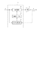
図1は、本発明の一実施形態に係る歪補償回路1の主要部を示すブロック図である。歪補償回路1は、高出力増幅器(HPA、以下、単に増幅器という。)5の出力信号Yを入力信号Xのn次べき級数の多項式の形で表したモデルを推定するモデル推定部2と、モデルの係数を一時的に記憶する係数テーブル3と、モデルに対する逆モデル(モデルの逆関数)を入力信号Xに付加することにより増幅器5の入出力特性の歪を打ち消す歪補償を行う歪補償部4とを備えている。モデル推定部2、係数テーブル3及び歪補償部4は、例えば、DSP(Digital Signal Processor)によって構成されている。なお、モデル推定部2には、入力信号X及び出力信号Yの両方が入力されている。
FIG. 1 is a block diagram showing a main part of a
増幅器5の非線形特性は、入力信号Xのべき級数多項式で表される。すなわち、出力信号をYとすると、以下のように表すことができる。なお、aiは各次の係数である。 The nonlinear characteristic of the amplifier 5 is expressed by a power series polynomial of the input signal X. That is, when the output signal is Y, it can be expressed as follows. Note that a i is a coefficient of each order.
ここで、Xの係数aiの値(絶対値)は、本来、次数が大きいほど小さくなる、ということが実験によりわかっている。すなわち、│a1│>│a2│> ...>│an-1│>│an│という規則性がある。
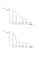
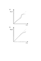
図2の(a)は、強い非線形性を有する増幅器の高調波スペクトルを示すグラフである。高調波スペクトルは、増幅器の非線形特性と密接な関係があり、高調波スペクトルの強度が大きな増幅器は非線形性が強い。この場合、モデルの多項式は高次(例えばn=10)まで必要である。
Here, it has been experimentally known that the value (absolute value) of the coefficient a i of X becomes smaller as the order increases. That is, │a 1 │> │a 2 │>. . . There is a regularity of | │a n-1 │> │a n │.
FIG. 2A is a graph showing a harmonic spectrum of an amplifier having strong nonlinearity. The harmonic spectrum is closely related to the nonlinear characteristics of the amplifier, and an amplifier having a large harmonic spectrum intensity has a strong nonlinearity. In this case, the polynomial of the model is required up to higher order (for example, n = 10).
一方、図2の(b)は、弱い非線形性を有する増幅器の高調波スペクトルを示すグラフである。このような弱い非線形性の場合、例えば4次以上のスペクトル強度が小さく、あまり高い次数成分は不要である。必要以上に高い次数における係数を無理矢理定めようとすると、係数が発散する。すなわち、次数が1次下の係数より大きいaiが出現し、上記の規則性は維持できなくなる。このようなモデルに対する逆モデルによって歪補償を行うと、過剰補償になる。すなわち、上記のように係数が発散する場合は、過剰補償の状態である。 On the other hand, FIG. 2B is a graph showing a harmonic spectrum of an amplifier having weak nonlinearity. In the case of such a weak non-linearity, for example, the spectral intensity of the fourth order or higher is small, and a very high order component is unnecessary. If you try to force a coefficient at an order higher than necessary, the coefficient will diverge. That is, a i whose order is larger than the coefficient under the first order appears, and the regularity cannot be maintained. If distortion compensation is performed using an inverse model for such a model, overcompensation occurs. That is, when the coefficient diverges as described above, it is an overcompensation state.
そこで、多項式における各次の係数が、次数が大きいほど小さいという規則性を維持しているか否かに基づいて、nの値を増減する機能をモデル推定部2に持たせる。
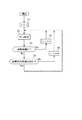
図3は、モデル推定部2における処理を示すフローチャートである。処理の開始後、モデル推定部2は、nの初期値を1として(ステップS1)、モデルの推定を行う(ステップS2)。その後、モデル推定部2は、過剰補償か否かの判断を行う(ステップS3)。ここでは係数がa1だけであるので、a1より大きいa2が存在するという事象は起こりえず、ステップS3の判断結果は「No」となる。
Therefore, the model estimation unit 2 is provided with a function of increasing / decreasing the value of n based on whether or not the regularity of each degree in the polynomial is smaller as the degree is larger.
FIG. 3 is a flowchart showing processing in the model estimation unit 2. After the start of the process, the model estimation unit 2 estimates the model by setting the initial value of n to 1 (step S1) (step S2). Thereafter, the model estimation unit 2 determines whether or not there is excessive compensation (step S3). Here, since the coefficient is only a 1 , an event that a 2 larger than a 1 exists cannot occur, and the determination result in step S3 is “No”.
次に、モデル推定部2は、モデルによって表された出力と、実際の出力との誤差が所定値以内(僅差)であるか否か、すなわち、モデルが適切かどうかの判断を行う(ステップS4)。この時点ではまだモデルは適切なレベルに達していないので、判断結果は「No」となる。従って、モデル推定部2は、nを1加算して(ステップS6)、再度モデル推定を行う(ステップS2)。このような処理が繰り返され、最初に誤差が所定値以内となった場合(ステップS4のYes)、一旦その次数に決定され、その次数でのモデル推定(ステップS2)が繰り返し行われる。 Next, the model estimation unit 2 determines whether or not the error between the output represented by the model and the actual output is within a predetermined value (slight difference), that is, whether the model is appropriate (step S4). ). Since the model has not yet reached an appropriate level at this point, the determination result is “No”. Accordingly, the model estimation unit 2 adds 1 to n (step S6) and performs model estimation again (step S2). Such processing is repeated, and when the error is initially within a predetermined value (Yes in step S4), the order is once determined, and model estimation (step S2) at that order is repeatedly performed.
一方、誤差が所定値以内になる前に過剰補償となってしまった場合や、上記のように一旦次数が決定された後、温度変化等により増幅器5の特性変化が生じたために過剰補償となった場合、すなわち、次数が1次下の係数より大きい係数が出現したときは、モデル推定部2は、nを1減じる処理を行う(ステップS5)。例えば、5次のモデル推定を行った結果、5次の係数a5が、4次の係数a4以上となった場合は、4次のモデル推定に戻る。従って、過剰補償になった場合には次数が1下がり、その結果、必要以上の次数でのモデル推定は行われない、ということになる。 On the other hand, when the error is overcompensated before it falls within the predetermined value, or after the order is determined once as described above, the characteristic of the amplifier 5 is changed due to a temperature change or the like. In other words, when a coefficient whose order is larger than the coefficient of the first order appears, the model estimation unit 2 performs a process of subtracting n from 1 (step S5). For example, when the fifth-order model estimation results in that the fifth-order coefficient a 5 is equal to or greater than the fourth-order coefficient a 4 , the process returns to the fourth-order model estimation. Therefore, when overcompensation occurs, the order is reduced by 1, and as a result, model estimation with an order greater than necessary is not performed.
また、上記のように一旦次数が決定された後、温度変化等により増幅器5の特性変化が生じたためにモデルが不適切となり、誤差が所定値以内でなくなった場合には、モデル推定部2は、nを1加算する処理を行う(ステップS6)。これにより、適切なモデルが再構築される。 In addition, after the order is once determined as described above, the model becomes inappropriate due to a change in the characteristics of the amplifier 5 due to a temperature change or the like, and when the error is not within a predetermined value, the model estimation unit 2 , N is incremented by 1 (step S6). Thereby, an appropriate model is reconstructed.
以上のような処理によって、高次が必要な場合は高次になり、逆に、必要以上の高次にはならないようにモデルが推定される。推定されたモデルの係数は、係数テーブル3に一時的に記憶される。歪補償部4は係数テーブル3を参照しながら逆モデルを求め、これを入力信号に付加することにより、歪補償を行う。
なお、上記とは別に、モデル推定部2で逆モデルまで求め、その係数を係数テーブル3に記憶させ、歪補償部4は係数テーブル3を参照しながら歪補償を行う、という構成であってもよい。
As a result of the above processing, the model is estimated so that the higher order is required, and the higher order is not required. The estimated model coefficients are temporarily stored in the coefficient table 3. The
In addition to the above, the model estimation unit 2 may obtain the inverse model and store the coefficients in the coefficient table 3, and the
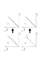
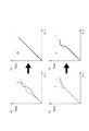
図4の(a)、(b)は、増幅器の入出力特性(実線)及び逆モデル(破線)の2例を示すグラフであり、横軸は入力信号振幅を、縦軸は出力信号振幅を、それぞれ示している。(a)に示す特性は形状が複雑で非線形性が大きく、逆モデルの次数は10次に達し、適切な逆モデルが与えられる。一方、(b)に示す特性は形状が単純で非線形性が小さく、逆モデルの次数は3次にとどまり、適切なモデルが与えられる。なお、点線は理想的な直線状の特性を示す。このような補償の結果、(a)及び(b)いずれの場合も、それぞれ(c)及び(d)に示すように、歪が取り除かれた入出力特性が得られる。 4A and 4B are graphs showing two examples of input / output characteristics (solid line) and inverse model (broken line) of the amplifier, where the horizontal axis represents the input signal amplitude and the vertical axis represents the output signal amplitude. , Respectively. The characteristic shown in (a) has a complicated shape and large nonlinearity. The order of the inverse model reaches the 10th order, and an appropriate inverse model is given. On the other hand, the characteristic shown in (b) has a simple shape and small nonlinearity, and the order of the inverse model is limited to the third order, and an appropriate model is given. The dotted line shows ideal linear characteristics. As a result of such compensation, in both cases (a) and (b), as shown in (c) and (d), input / output characteristics from which distortion has been removed are obtained.
(b)の場合は次数が低いことにより、モデル推定の演算が簡単になり、その分、演算速度が速くなる。すなわち、必要以上に次数を上げないことにより、比較的低次の演算が増加することになり、高速な歪補償に寄与する。 In the case of (b), since the order is low, the calculation of model estimation is simplified, and the calculation speed is increased accordingly. That is, if the order is not increased more than necessary, relatively low-order operations increase, which contributes to high-speed distortion compensation.
以上のように、本実施形態に係る歪補償回路1又は当該回路1によって実行される歪補償方法では、多項式の最大次数であるnを固定値とせず、係数の規則性に着目してモデルの適否を判定し、適切なモデルとなるように増減することができる。特に、過剰補償になる場合には最大次数を下げることができるので、過剰補償を防止する歪補償回路1又は歪補償方法を提供することができる。
As described above, in the
また、規則性に反する係数が出現した場合、モデル推定部2が、次数を1減少させてモデルを推定することにより、過剰補償になる直前の次数で、モデルの推定を行うことができる。
また、1から順に各次の係数が規則性を維持し、かつ、モデルと実際の出力信号との誤差が所定値以内となったときの当該次数を、モデル推定部2が、nの値とすることにより、規則性の維持によって過剰補償を排除し得る範囲内で、正確なモデルを推定することができる。
In addition, when a coefficient contrary to regularity appears, the model estimation unit 2 can estimate the model with the order immediately before overcompensation by reducing the order by 1 and estimating the model.
Further, each order coefficient maintains regularity in order from 1, and when the error between the model and the actual output signal is within a predetermined value, the model estimation unit 2 determines that the value of n By doing so, an accurate model can be estimated within a range in which overcompensation can be eliminated by maintaining regularity.
この論理は、メモリ効果補償を必要とする増幅器への歪補償にも、同様に適応される。つまり、過去の状態が現在の非直線性に影響を与える増幅器においても、現在の非直線性に影響を与えている任意の過去時の逆モデル特性のべき級数の各次数の係数が、次数が小さくなるに従って係数の値が小さくならなければ、次数を減らすことにより過剰補償を防ぐことができる。 This logic is similarly applied to distortion compensation for amplifiers that require memory effect compensation. In other words, even in an amplifier whose past state affects the current nonlinearity, the coefficient of each order of the power series of the inverse model characteristic at any past time that affects the current nonlinearity is If the value of the coefficient does not decrease as it decreases, overcompensation can be prevented by reducing the order.
なお、今回開示された実施の形態はすべての点で例示であって制限的なものではないと考えられるべきである。本発明の範囲は、上記した意味ではなく、特許請求の範囲によって示され、特許請求の範囲と均等の意味及び範囲内での全ての変更が含まれることが意図される。 The embodiment disclosed this time should be considered as illustrative in all points and not restrictive. The scope of the present invention is defined not by the above-mentioned meaning but by the scope of claims for patent, and is intended to include all modifications within the scope and meaning equivalent to the scope of claims for patent.
1 歪補償回路
2 モデル推定部
3 係数テーブル
4 歪補償部
5 増幅器
DESCRIPTION OF
Claims (4)
前記モデルに対する逆モデルを前記入力信号に付加することにより前記増幅器の入出力特性の歪を打ち消す歪補償を行う歪補償部と、を備えた歪補償回路であって、
前記モデル推定部は、前記多項式における各次の係数が、次数が大きいほど小さいという規則性を維持しているか否かに基づいて、nの値を増減する機能を有することを特徴とする歪補償回路。 A model estimator for estimating a model representing the output signal of the amplifier in the form of a polynomial of the nth power series of the input signal;
A distortion compensation circuit that performs distortion compensation to cancel distortion of input and output characteristics of the amplifier by adding an inverse model to the input signal to the input signal,
The model estimation unit has a function of increasing / decreasing the value of n based on whether or not each order coefficient in the polynomial maintains the regularity that the degree is smaller as the degree is larger. circuit.
前記多項式における各次の係数が、次数が大きいほど小さいという規則性を維持しているか否かに基づいてnの値を増減し、
1から順に各次の係数が前記規則性を維持し、かつ、前記モデルと実際の前記出力信号との誤差が所定値以内となったときの当該次数を前記nの値とする
ことを特徴とする歪補償方法。 Distortion compensation that estimates the model of the output signal of the amplifier in the form of a polynomial of the nth power series of the input signal, and adds the inverse model to the model to the input signal to cancel the distortion of the input / output characteristics of the amplifier A distortion compensation method for performing
The value of n is increased or decreased based on whether or not each degree of coefficient in the polynomial maintains the regularity that the larger the degree is, the smaller the degree is.
Each order coefficient in order from 1 maintains the regularity, and the order when the error between the model and the actual output signal is within a predetermined value is the value of n. Distortion compensation method.
Priority Applications (1)
| Application Number | Priority Date | Filing Date | Title |
|---|---|---|---|
| JP2008171169A JP5141403B2 (en) | 2008-06-30 | 2008-06-30 | Distortion compensation circuit and distortion compensation method |
Applications Claiming Priority (1)
| Application Number | Priority Date | Filing Date | Title |
|---|---|---|---|
| JP2008171169A JP5141403B2 (en) | 2008-06-30 | 2008-06-30 | Distortion compensation circuit and distortion compensation method |
Publications (2)
| Publication Number | Publication Date |
|---|---|
| JP2010011348A true JP2010011348A (en) | 2010-01-14 |
| JP5141403B2 JP5141403B2 (en) | 2013-02-13 |
Family
ID=41591244
Family Applications (1)
| Application Number | Title | Priority Date | Filing Date |
|---|---|---|---|
| JP2008171169A Expired - Fee Related JP5141403B2 (en) | 2008-06-30 | 2008-06-30 | Distortion compensation circuit and distortion compensation method |
Country Status (1)
| Country | Link |
|---|---|
| JP (1) | JP5141403B2 (en) |
Cited By (3)
| Publication number | Priority date | Publication date | Assignee | Title |
|---|---|---|---|---|
| JP2011193154A (en) * | 2010-03-12 | 2011-09-29 | Fujitsu Ltd | Radio apparatus, distortion correction device, and distortion correction method |
| JP2011233978A (en) * | 2010-04-23 | 2011-11-17 | Fujitsu Ltd | Distortion compensation device, radio communication equipment and distortion compensation method |
| WO2013145748A1 (en) * | 2012-03-30 | 2013-10-03 | 日本電気株式会社 | Amplifier and amplification method |
Citations (2)
| Publication number | Priority date | Publication date | Assignee | Title |
|---|---|---|---|---|
| JPH0786844A (en) * | 1993-09-14 | 1995-03-31 | Fujitsu Ltd | Low distortion factor amplifier |
| JP2007336474A (en) * | 2006-06-19 | 2007-12-27 | Handotai Rikougaku Kenkyu Center:Kk | Signal processing method, and signal processing apparatus |
-
2008
- 2008-06-30 JP JP2008171169A patent/JP5141403B2/en not_active Expired - Fee Related
Patent Citations (2)
| Publication number | Priority date | Publication date | Assignee | Title |
|---|---|---|---|---|
| JPH0786844A (en) * | 1993-09-14 | 1995-03-31 | Fujitsu Ltd | Low distortion factor amplifier |
| JP2007336474A (en) * | 2006-06-19 | 2007-12-27 | Handotai Rikougaku Kenkyu Center:Kk | Signal processing method, and signal processing apparatus |
Cited By (4)
| Publication number | Priority date | Publication date | Assignee | Title |
|---|---|---|---|---|
| JP2011193154A (en) * | 2010-03-12 | 2011-09-29 | Fujitsu Ltd | Radio apparatus, distortion correction device, and distortion correction method |
| JP2011233978A (en) * | 2010-04-23 | 2011-11-17 | Fujitsu Ltd | Distortion compensation device, radio communication equipment and distortion compensation method |
| WO2013145748A1 (en) * | 2012-03-30 | 2013-10-03 | 日本電気株式会社 | Amplifier and amplification method |
| US9219448B2 (en) | 2012-03-30 | 2015-12-22 | Nec Corporation | Amplifier and amplification method |
Also Published As
| Publication number | Publication date |
|---|---|
| JP5141403B2 (en) | 2013-02-13 |
Similar Documents
| Publication | Publication Date | Title |
|---|---|---|
| JP5420887B2 (en) | Distortion compensation device | |
| JP4935906B2 (en) | Distortion compensation apparatus and method | |
| JP5751056B2 (en) | Distortion compensation apparatus, transmitter, and distortion compensation method | |
| JP2006279780A (en) | Distortion compensation apparatus and distortion correction method | |
| JP6054739B2 (en) | Distortion compensation apparatus and distortion compensation method | |
| US7340005B2 (en) | Signal transmission apparatus and method | |
| JP5141403B2 (en) | Distortion compensation circuit and distortion compensation method | |
| JP2006261952A (en) | Distortion compensation device and distortion compensation coefficient updating method | |
| US8964893B2 (en) | Predistortion apparatus for power amplifier | |
| JP4973532B2 (en) | Amplifier circuit, wireless communication apparatus and computer program having the same | |
| JP2018011139A (en) | Distortion compensation apparatus and distortion compensation method | |
| US20150077179A1 (en) | Distortion compensation apparatus, transmission apparatus, and distortion compensation method | |
| JP4935677B2 (en) | Distortion compensation device | |
| JP5316325B2 (en) | Distortion compensation circuit, radio transmitter using the same, and distortion compensation method | |
| JP6064374B2 (en) | Distortion compensation apparatus and distortion compensation method | |
| JP5387445B2 (en) | Predistortion compensation circuit and memory effect distortion compensation method for power amplifier | |
| JP2015099972A (en) | Transmitter module | |
| JP2018142798A (en) | Amplifier and communication device | |
| JP2016001846A (en) | Distortion compensation device and distortion compensation method | |
| JP6296709B2 (en) | Distortion compensation device | |
| JP2010272923A (en) | Distortion compensating amplifier and predistorter | |
| JP2010016422A (en) | Distortion compensation circuit | |
| JP5673276B2 (en) | Compensation error reduction method and compensation error reduction apparatus in nonlinear distortion compensation | |
| KR101105903B1 (en) | Apparatus and method for digital predistortion using adaptive noise cancelation | |
| KR101952207B1 (en) | Digital pre distortion apparatus and method there of |
Legal Events
| Date | Code | Title | Description |
|---|---|---|---|
| A621 | Written request for application examination |
Free format text: JAPANESE INTERMEDIATE CODE: A621 Effective date: 20110126 |
|
| A977 | Report on retrieval |
Free format text: JAPANESE INTERMEDIATE CODE: A971007 Effective date: 20111222 |
|
| A131 | Notification of reasons for refusal |
Free format text: JAPANESE INTERMEDIATE CODE: A131 Effective date: 20120807 |
|
| A521 | Written amendment |
Free format text: JAPANESE INTERMEDIATE CODE: A523 Effective date: 20120920 |
|
| TRDD | Decision of grant or rejection written | ||
| A01 | Written decision to grant a patent or to grant a registration (utility model) |
Free format text: JAPANESE INTERMEDIATE CODE: A01 Effective date: 20121023 |
|
| A01 | Written decision to grant a patent or to grant a registration (utility model) |
Free format text: JAPANESE INTERMEDIATE CODE: A01 |
|
| A61 | First payment of annual fees (during grant procedure) |
Free format text: JAPANESE INTERMEDIATE CODE: A61 Effective date: 20121105 |
|
| FPAY | Renewal fee payment (event date is renewal date of database) |
Free format text: PAYMENT UNTIL: 20151130 Year of fee payment: 3 |
|
| R150 | Certificate of patent or registration of utility model |
Free format text: JAPANESE INTERMEDIATE CODE: R150 |
|
| R250 | Receipt of annual fees |
Free format text: JAPANESE INTERMEDIATE CODE: R250 |
|
| LAPS | Cancellation because of no payment of annual fees |