JP2010009538A - Information processor - Google Patents
Information processor Download PDFInfo
- Publication number
- JP2010009538A JP2010009538A JP2008171486A JP2008171486A JP2010009538A JP 2010009538 A JP2010009538 A JP 2010009538A JP 2008171486 A JP2008171486 A JP 2008171486A JP 2008171486 A JP2008171486 A JP 2008171486A JP 2010009538 A JP2010009538 A JP 2010009538A
- Authority
- JP
- Japan
- Prior art keywords
- battery
- power
- mode
- power supply
- computer
- Prior art date
- Legal status (The legal status is an assumption and is not a legal conclusion. Google has not performed a legal analysis and makes no representation as to the accuracy of the status listed.)
- Pending
Links
Images


Landscapes
- Power Sources (AREA)
Abstract
Description
本発明は、バッテリを備えた情報処理装置に係り、特にバッテリの充電時間を効率よく短縮することができる情報処理装置に関する。 The present invention relates to an information processing apparatus including a battery, and more particularly, to an information processing apparatus capable of efficiently shortening a battery charging time.
一般に、充放電が可能なバッテリを備えたパーソナルコンピュータ等においては、バッテリを充電するのにACアダプタ等の外部電源が用いられる。外部電源からコンピュータ装置へ供給される電力は限られており、限られた電力を使って、コンピュータ装置の動作やバッテリの充電を行う。このため、コンピュータ装置が動作中の場合は、外部電源からの電力の多くは、コンピュータ装置を動作させるために使用されるため、バッテリを充電するに使える電力は僅かとなる。例えば、特許文献1では、専用の設定画面で、コンピュータ装置が動作中に充電を行う場合の充電内容について、ユーザが指定する事が可能となる技術が開示されている。 Generally, in a personal computer or the like equipped with a chargeable / dischargeable battery, an external power source such as an AC adapter is used to charge the battery. The power supplied from the external power source to the computer device is limited, and the computer device is operated and the battery is charged using the limited power. For this reason, when the computer device is in operation, much of the power from the external power source is used to operate the computer device, so that little power can be used to charge the battery. For example, Patent Document 1 discloses a technique that allows a user to specify charging contents when charging is performed while a computer device is operating on a dedicated setting screen.
当該技術によると、ユーザが充電優先モードを選択すると、CPUの動作スピードを遅くする制御を行う、または画面の明るさを暗くしたりする制御等を行う。これにより、コンピュータ装置本体の消費電力を低減し、バッテリへの充電電力を増加し、より短時間に充電を完了させることが可能となっている。
しかしながら、特許文献1に記載された技術では、充電優先モードが選択されている時は、CPUの動作スピードを遅くする制御を行う場合、本来のパフォーマンスでコンピュータ装置を動作することはできない。このため、大量の動画を処理する等の過大な処理が必要な時は、ユーザは処理が完了するまで長時間待つか、または、コンピュータ装置を本来のパフォーマンスで動作させるために、専用の設定画面にアクセスして設定を解除する必要があり、煩雑である。 However, in the technique described in Patent Document 1, when the charge priority mode is selected, the computer apparatus cannot be operated with the original performance when the control for reducing the operation speed of the CPU is performed. For this reason, when excessive processing such as processing a large amount of video is required, the user waits for a long time until the processing is completed, or a dedicated setting screen for operating the computer device at its original performance It is necessary to access and cancel the setting, which is complicated.
そこで、本発明は、容易に動作モードの切り替えを行うことができる情報処理装置を提供することを目的とする。 Accordingly, an object of the present invention is to provide an information processing apparatus that can easily switch operation modes.
上述した課題を解決するために、本発明の一態様によれば、充放電可能なバッテリとデバイスとを備えた情報処理装置であって、前記バッテリおよび前記デバイスに電源を供給する電源部と、前記電源部から前記デバイスに電力を供給する処理優先モードと、前記デバイスを前記処理優先モードよりも消費電力の少ない省電力動作モードに移行させて前記電源部から前記バッテリへの電力供給を優先させる充電モードとを切り替える切替ボタンと、前記切替ボタンの押下を検出し、前記処理優先モードと充電モードとを切り替える制御、および前記バッテリの残容量を検出し、検出された前記バッテリの残容量に従って前記処理優先モードと充電モードとを切り替える制御を行う制御部とを備えることを特徴とする情報処理装置が提供される。 In order to solve the above-described problem, according to one aspect of the present invention, an information processing apparatus including a chargeable / dischargeable battery and a device, the power supply unit supplying power to the battery and the device, Priority is given to power supply from the power supply unit to the battery by shifting the power supply unit to a processing priority mode for supplying power to the device and a power saving operation mode in which the device consumes less power than the processing priority mode. A switching button for switching between charging modes, a control for detecting the pressing of the switching button, switching between the processing priority mode and the charging mode, and detecting the remaining capacity of the battery, and according to the detected remaining capacity of the battery There is provided an information processing apparatus including a control unit that performs control to switch between a processing priority mode and a charging mode.
本発明によれば、容易に動作モードの切り替えを行うことができる情報処理装置を提供することができる。 ADVANTAGE OF THE INVENTION According to this invention, the information processing apparatus which can switch an operation mode easily can be provided.
以下、本発明の実施形態について図面を参照しながら説明する。 Hereinafter, embodiments of the present invention will be described with reference to the drawings.
まず、図1および図2を参照して、本発明の一実施形態に係るコンピュータの構成について説明する。この情報処理装置は、例えば、ノートブック型パーソナルコンピュータ10として実現されている。
First, the configuration of a computer according to an embodiment of the present invention will be described with reference to FIG. 1 and FIG. This information processing apparatus is realized as, for example, a notebook
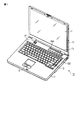
図1は、ノートブック型パーソナルコンピュータ10のディスプレイユニットを開いた状態における斜視図である。本コンピュータ10は、コンピュータ本体11と、ディスプレイユニット12とから構成されている。ディスプレイユニット12には、LCD(Liquid Crystal Display)17から構成される表示装置が組み込まれており、そのLCD17の表示画面は、ディスプレイユニット12のほぼ中央に位置されている。
FIG. 1 is a perspective view of the notebook
ディスプレイユニット12は、コンピュータ本体11に対して開放位置と閉塞位置との間を回動自在に取り付けられている。コンピュータ本体11は薄い箱形の筐体を有しており、その上面にはキーボード13、本コンピュータ10を電源オン/オフするためのパワーボタン14、入力操作パネル15、タッチパッド16および光ディスクドライブ(ODD)20などが配置されている。
The
入力操作パネル15は、押下されたボタンに対応するイベントをシステムに入力する入力装置であり、複数の機能をそれぞれに起動するための複数のボタンを備えている。これらボタン群には、動作モード切り替えボタン15A、TV起動ボタン、DVD(Digital Versatile Disc)起動ボタンが含まれている。コンピュータ10が備えている各種デバイス(後述するCPU111、LCD17等)の動作ステートが、例えば、ACPI(Advanced Configuration and Power Interface)の仕様で規定されたデバイスステートD1およびD2(省電力動作モード)である場合でかつACアダプタ127から電源が供給されている場合は、動作モード切り替えボタン15Aを押下することにより、処理優先モードであるデバイスステートD0にモードを切り替えることができる(図8参照)。TV起動ボタンは、デジタルTV放送番組のような放送番組データの再生及び記録を行うためのTV機能を起動するためのボタンであり、ユーザによって押下されると、このTV機能を実行するためのTVアプリケーションプログラムが起動される。また、DVD起動ボタンは、DVDに記録されたビデオコンテンツを再生するためのボタンであり、ユーザによって押下されると、ビデオコンテンツを再生するためのアプリケーションプログラムが自動的に起動される。
The
次に、図2を参照して、本コンピュータ10のシステム構成について説明する。
Next, the system configuration of the
本コンピュータ10は、図2に示されているように、CPU111、ノースブリッジ112、(主)メモリ113、グラフィクスコントローラ114、サウスブリッジ119、BIOS−ROM120、ハードディスクドライブ(HDD)121、光ディスクドライブ(ODD)122、エンベデッドコントローラ/キーボードコントローラIC(EC/KBC)124、パワーボタン14、動作モード切り替えボタン15A、電源コントローラ123、電源回路126、バッテリ50、ACアダプタ(電源部)127およびネットワークコントローラ125等を備えている。
As shown in FIG. 2, the
CPU111は、本コンピュータ10の動作を制御するために設けられたプロセッサであり、ハードディスクドライブ(HDD)121から主メモリ113にロードされる、オペレーティングシステム(OS)および電源制御アプリケーション(制御部、切替部)201のような各種アプリケーションを実行する。
The
また、CPU111は、BIOS−ROM120に格納されたシステムBIOS(Basic Input Output System)も実行する。システムBIOSはハードウェア制御のためのプログラムである。
The
ノースブリッジ112はCPU111のローカルバスとサウスブリッジ119との間を接続するブリッジデバイスである。ノースブリッジ112には、主メモリ113をアクセス制御するメモリコントローラも内蔵されている。また、ノースブリッジ112は、AGP(Accelerated Graphics Port)バスなどを介してグラフィクスコントローラ114との通信を実行する機能も有している。
The
グラフィクスコントローラ114は本コンピュータ10のディスプレイモニタとして使用されるLCD17を制御する表示コントローラである。このグラフィクスコントローラ114はビデオメモリ(VRAM)114Aに書き込まれた画像データからLCD17に送出すべき表示信号を生成する。
The
サウスブリッジ119は、LPC(Low Pin Count)バス上の各デバイス、およびPCI(Peripheral Component Interconnect)バス上の各デバイスを制御する。また、サウスブリッジ119は、HDD121、ODD122を制御するためのIDE(Integrated Drive Electronics)コントローラを内蔵している。
The
HDD121は、各種ソフトウェア及びデータを格納する記憶装置である。光ディスクドライブ122は、ビデオコンテンツが格納されたDVDなどの記憶メディアを駆動するためのドライブユニットである。
The HDD 121 is a storage device that stores various software and data. The
エンベデッドコントローラ/キーボードコントローラIC(EC/KBC)124は、電力管理のためのエンベデッドコントローラと、キーボード(KB)13およびタッチパッド16を制御するためのキーボードコントローラとが集積された1チップマイクロコンピュータである。このエンベデッドコントローラ/キーボードコントローラIC(EC/KBC)124は、ユーザによるパワーボタン14の操作に応じて本コンピュータ10を電源オン/オフする機能を有している。電源コントローラ123は、ACアダプタ127またはバッテリ50から供給された電力をコンピュータ10の各種デバイスおよびバッテリに供給する制御等を行う。電源回路126は、ACアダプタ127またはバッテリ50から供給される電力の電力変換等を行う。バッテリ50は、充放電が可能なセルを備えており、ACアダプタ127からまたはバッテリ50供給される電力により充電を行うことができる。ネットワークコントローラ125は、例えばインターネットなどの外部ネットワークとの通信を実行する通信装置である。
The embedded controller / keyboard controller IC (EC / KBC) 124 is a one-chip microcomputer in which an embedded controller for power management and a keyboard controller for controlling the keyboard (KB) 13 and the
電源制御アプリケーション200は、ACアダプタ127から電源が供給されている場合、動作モード切り替えボタン15Aの押下による動作モードの切り替えを行う(図8参照)。また、デバイスステートにおける省電力動作モードは、D1、D2が規定されている。デバイスの電力消費量は、D1>D2となるため、D1は充電優先モード時に適用し、D2を充電最優先モード時に適用する。電源制御アプリケーション200は、バッテリ50の残容量に応じて、充電優先モード(デバイスステートはD1)、充電最優先モード(デバイスステートはD2)を切り替える制御を行う(図8参照)。
When power is supplied from the
図3は、ACアダプタ127またはバッテリ50から電源コントローラ123の制御によりバッテリ50や各種デバイス(所定のデバイス)に電力が供給される状態を模式的に示した図である。
FIG. 3 is a diagram schematically showing a state in which power is supplied from the
ACアダプタ127は、ACアダプタ127とコンピュータ10とのコネクタである接続部127aを介してコンピュータ10に接続されて電力を供給している。
The
バッテリ50の電力は、各種デバイス(CPU111、HDD121、ネットワークコントローラ125、LCD17、外部機器52等)へ供給される。また、ダイオード61により、ACアダプタ127の電圧およびバッテリ50の電圧のどちらか高い電圧の電力供給源から各機器へ電力が供給される。
The power of the
接続部127aは、ACアダプタ127とコンピュータ10とを接続するためのコネクタ機構を備えている。また、接続部127aからの信号により、電源コントローラ123がACアダプタ127の接続有無を判別する。
The
例えば、接続部127aでは、ACアダプタ127の電圧を測定する。測定された電圧が電源コントローラ123へ入力されると、電圧がある範囲内にある場合、ACアダプタ127がコンピュータ10に接続されていると判別する。例えば、ACアダプタ127の出力電圧が15V±10%である時、接続部127aで測定される電圧が、13.5V〜16.5Vの範囲にあれば、ACアダプタ127がコンピュータ10に接続されていると判別する。
For example, the
接続部127aで測定された電圧が、例えば13.5V未満または16.5Vを越える電圧の場合、ACアダプタ127がコンピュータ10に接続されていない(またはコンピュータ10に接続されているACアダプタ127が正常でない)と判別する。
When the voltage measured at the
スイッチ部60は、バッテリ50の充電オン/オフを切り替えるためのものであり、電源コントローラ123の出力部903からの信号により制御される。
The
電源コントローラ123は、コンピュータ10にACアダプタ127が接続されており、バッテリ50の充電が可能と判別すると、スイッチ部60をオンし、ACアダプタ127からの電力によりバッテリ50を充電する。スイッチ部60がオフされると、バッテリ50への充電は停止される(バッテリ50が満充電となるとスイッチ部60をオフする制御を行う)。
When it is determined that the
バッテリ50の電圧は、電圧測定部54で測定され、測定結果が電源コントローラ123の入力部902へ入力される。同様にバッテリ50の充放電電流は、電流測定部53で測定され、測定結果が電源コントローラ123の入力部902へ入力される。
The voltage of the
LCD17は、バックライト17aを備えており、LCD17を発光させるための光源である。このバックライト17aは、電源コントローラ123の出力部903からの要求で輝度を変化させることができる。
The
次に、図4は電源制御アプリケーション200の機能構成を示したブロック図である。電源制御アプリケーション200は、設定制御部201と設定記憶部202を備える。設定制御部201は、設定記憶部202に記憶された設定情報に従ってACアダプタ127から供給された電力をバッテリ50および各種デバイスに供給する。バッテリ50の残容量やCPU111の処理負荷によって、バッテリ50に電力を多く供給させたり、CPU111等の各種デバイスに電力を多く供給させる等の制御を行う。設定記憶部202は、バッテリ50の残容量の閾値(例えば残容量60%、30%等)の情報や電力の供給の制御方法の設定情報等を記憶する。すなわち、コンピュータ10の電力設定を行うための設定部であり、コンピュータ10を省電力で動作させてバッテリ50の充電を優先する設定または、各種デバイスの処理を優先させてコンピュータ10を動作させる制御を行い、バッテリ50の充電は優先しない設定等を行う。この設定情報は、電源コントローラ123の入力部902へ入力され、電源コントローラ123の出力部903を介して、各機器の電力制御を行う。
Next, FIG. 4 is a block diagram showing a functional configuration of the power
例えば、ディスプレイ15の電力の消費を抑えたい場合は、電源コントローラ123は、バックライト17aを制御し、ディスプレイ15の輝度を暗くするように変更する。
For example, when it is desired to suppress power consumption of the
また、コンピュータ10の電源がオフであれば、ACアダプタ127の電力のほぼ全てをバッテリ50の充電に使用することができる。しかし、コンピュータ10の電源がオンであるときは、CPU111や各機器が動作するのに必要な電力をACアダプタ127が供給可能な電力から引いた電力(余剰電力)がバッテリ50の充電に使用できる。コンピュータ10が省電力で動作していれば余剰電力は大きく、コンピュータ10が処理能力を優先させて動作している時は、余剰電力は小さくなる。この様に、コンピュータ10の動作状態によって余剰電力は変化し、余剰電力が大きければ、より短い時間でバッテリ50を充電する事が可能であり、余剰電力が小さくなると、バッテリ50の充電時間は長くなる。よって、コンピュータ10の動作中にバッテリ50を充電する場合、より短い時間で充電を行いたい場合は、コンピュータ10の各種デバイスを省電力で動作させるように設定を行う。
Further, when the
そして、バッテリ50の充電中に短時間で処理を完了したい場合や、大量のデータを処理したいような場合、コンピュータ10は省電力状態で動作しているので、通常より多くの時間を費やしたり、動画再生などの場合では、画面がなめらかに映らない場合がある。この様な時に、動作モード切り替えボタン15Aを押下することにより、コンピュータ10を省電力動作状態から解除することができ、コンピュータ10を処理優先で動作させることができる。コンピュータ10を再び省電力状態へ戻す場合は、動作モード切り替えボタン15Aを押下することで、省電力状態へ復帰する(図8参照)。
And if you want to complete the process in a short time while charging the
以上のように構成された本発明の情報処理装置を適用した制御方法の処理について図5のフローチャートを参照して説明する。 Processing of the control method to which the information processing apparatus of the present invention configured as described above is applied will be described with reference to the flowchart of FIG.
CPU111によりメモリ113に電源制御アプリケーション201がロードされる。CPU111によって制御される電源制御アプリケーション201は、コンピュータ10の電源が入っている(パワーオン)か否かを判別する(ステップS101)。ステップS101で電源制御アプリケーション201によってコンピュータ10の電源が入っていると判別されると(ステップS101のYES)、電源制御アプリケーション201は、コンピュータ10にACアダプタ127から電源が供給されているか否かを判別する(ステップS102)。電源制御アプリケーション201は、ACアダプタ127から電源が供給されているかを電源コントローラ123からの情報(電源コントローラ123が接続部127aから受信した情報)に基づいて判別する。例えば、接続部127aでは、ACアダプタ127の電圧を測定し、測定された電圧が電源コントローラ123へ入力される。例えばACアダプタ127の出力電圧が15V±10%である時、接続部127aで測定される電圧が13.5V〜16.5Vの範囲にあれば、ACアダプタ127がコンピュータ10に接続されていると判別する。ステップS102で、電源制御アプリケーション201によって、コンピュータ10にACアダプタ127から電源が供給されていないと判別されると(ステップS102のNO)、バッテリ動作モードとなり、コンピュータ10の各種デバイスを省電力動作モードとする(ステップS103)。コンピュータ10の各種デバイスを省電力動作モードとすることで、コンピュータ10のバッテリ50の消費を抑えるようにする。
The
一方、ステップS101で電源制御アプリケーション201によってコンピュータ10の電源が入っていると判別されると(ステップS101のYES)、電源制御アプリケーション200は、バッテリ50の残容量が例えば30%以下か否かを判別する(ステップS104)。ステップS104で電源制御アプリケーション200によってバッテリ50の残容量が30%以下であると判別された場合は(ステップS104のYES)、電源制御アプリケーション200によってバッテリ充電最優先モードに移行する(ステップS105)。バッテリ充電最優先モードでは、各種デバイスを一番深い省電力状態となるように制御を行う。例えば、CPU111の動作クロック数を設定可能な範囲で出来る限り低く設定する。また、LCD17のバックライト17aに輝度を設定可能な範囲で一番低くする等の制御を行う。このように、バッテリ充電最優先モードに移行することで、各種デバイスの消費電力が低く抑えられるため、バッテリ50の充電を行う電力を多く当てることができるため、バッテリ50の充電時間を最も短縮させることができる。
On the other hand, when the power
次に、電源制御アプリケーション200はバッテリ優先モード(上述したバッテリ充電最優先モードよりもバッテリ50への充電を優先しないモード)に切り替えるか否かを判別する(ステップS106)。ステップS106で電源制御アプリケーション200によってバッテリ優先モードに切り替えると判別された場合(例えば、動作モード切り替えボタン15Aの押下を検出した場合)、電源制御アプリケーション200によってバッテリ優先モードに切り替える(ステップS108)。なお、ACアダプタ127から電源が供給されている場合は、動作モード切り替えボタン15Aの押下により、図8に示すように、「バッテリ最優先モード」、「バッテリ優先モード」、「処理優先モード」の3つモードを順に切り替えることができる。
Next, the power
一方、ステップS104で電源制御アプリケーション200によってバッテリ50の残容量が30%以下でないと判別された場合は(ステップS104のNO)、電源制御アプリケーション200は、バッテリ50の残容量が例えば60%以下か否かを判別する(ステップS107)。ステップS107で電源制御アプリケーション200によってバッテリ50の残容量が60%以下でないと判別された場合は(ステップS107のNO)、電源制御アプリケーション200は、処理優先モード(通常動作モード)に移行する制御を行う(ステップS109)。なお、処理優先モード(通常動作モード)は、コンピュータ10の各種デバイスへの電力供給が多い場合はバッテリの充電を行わない場合がある。
On the other hand, when the power
一方、ステップS107で電源制御アプリケーション200によってバッテリ50の残容量が60%以下であると判別された場合は(ステップS107のYES)、電源制御アプリケーション200は、バッテリ充電優先モードに移行する制御を行う(ステップS108)。バッテリ充電優先モードは、バッテリ充電最優先モードよりもデバイスステートの省電力を低いレベルで行う。例えば、CPU111の動作クロック数を設定可能な一番低いクロック数の1段階上のレベルのクロックに設定する。また、LCD17のバックライト17aに輝度を設定可能な範囲で一番低い設定であったものを2番目に低い輝度に設定する等の制御を行う。このように、バッテリ充電優先モードに移行することで、処理優先モードよりも各種デバイスの消費電力が低く抑えられるため、バッテリ50の充電を行う電力を多く当てることができる。このため、処理優先モードよりもバッテリ50の充電時間を短縮させることができる。
On the other hand, if the power
次に、電源制御アプリケーション200は、バッテリ充電最優先モードに切り替えるか否かを判別する(ステップS110)。ステップS110で電源制御アプリケーション200によってバッテリ充電最優先モードに切り替えると判別されると(動作モード切り替えボタン15Aの押下を検出した場合等、ステップS110のYES)、ステップS105に遷移する。一方、ステップS110で電源制御アプリケーション200によってバッテリ充電最優先モードに切り替えないと判別されると(ステップS110のNO)、電源制御アプリケーション200は、処理優先モードに切り替えるか否かを判別する(ステップS111)。ステップS111で電源制御アプリケーション200によって処理優先モードに切り替えると判別されると(ステップS111のYES)、処理優先モードに切り替える処理を行う(ステップS109)。一方、ステップS111で電源制御アプリケーション200によって処理優先モードに切り替えないと判別されると(ステップS111のNO)、電源制御アプリケーション200は、バッテリの残容量が例えば95%以上か否かを判別する(ステップS112)。ステップS112で電源制御アプリケーション200によってバッテリの残容量が例えば95%以上であると判別されると(ステップS112のYES)、処理優先モードに切り替える処理を行う(ステップS109)一方、ステップS112で電源制御アプリケーション200によってバッテリの残容量が例えば95%以上でないと判別されると(ステップS112のNO)、バッテリ充電優先モードに切り替える処理を行う(ステップS108)。
Next, the power
一方、ステップS106で電源制御アプリケーション200によってバッテリ充電最優先モードに切り替えないと判別された場合(ステップS106のNO)、電源制御アプリケーション200は、処理優先モードに切り替えるか否かを判別する(ステップS113)。ステップS113で電源制御アプリケーション200によって処理優先モードに切り替えると判別されると(ステップS113のYES)、処理優先モードに切り替える処理を行う(ステップS109)。一方、ステップS113で電源制御アプリケーション200によって処理優先モードに切り替えないと判別されると(ステップS113のNO)、ステップS112に遷移する。なお、動作モード切り替えボタン15Aに替えてコンピュータ10のキーボード13の所定のキーを用いて動作モードの切り替えボタンとして兼用することもできる。
On the other hand, when it is determined in step S106 that the power
上述した実施形態によれば、バッテリの充電を優先させつつも、必要に応じて動作モードを容易に切り替えることができる。例えば、専用もしくは兼用のボタンにより、充電優先モードの解除が容易に行うことができる。また、充電優先モードによりコンピュータ装置のパフォーマンスが低下している状態で、過大な負荷が発生し、より高いパフォーマンスが求められる様な状況になった時、ボタンの押下により、容易に充電優先モードが解除して、コンピュータ装置のパフォーマンスを上げることが可能である。これにより、ユーザは、使い勝手に応じて、充電優先とパフォーマンス優先を切り替えが可能となる。 According to the above-described embodiment, it is possible to easily switch the operation mode as necessary while giving priority to the charging of the battery. For example, the charge priority mode can be easily canceled by using a dedicated or dual-purpose button. In addition, when the performance of the computer device is degraded due to the charge priority mode, an excessive load occurs and a higher performance is required. It is possible to improve the performance of the computer device. As a result, the user can switch between the charging priority and the performance priority according to usability.
さらに本実施形態の変形例としては、以下の形態も考えられる。上述した実施形態では、動作モード切り替えボタン15Aの押下、またはバッテリの残容量に応じて動作モードの切り替えを行っているが、コンピュータ10のCPU111の処理の負荷状況を電源制御アプリケーション200により監視を行い、所定の負荷(例えば、CPU111使用率100%)に達すると、電源制御アプリケーション200により処理優先モードに切り替える制御を行うこともできる。また、所定の負荷を下回った場合は、バッテリ充電優先モードまたはバッテリ充電最優先モードに切り替える制御を行う。
Furthermore, as a modification of the present embodiment, the following forms are also conceivable. In the above-described embodiment, the operation
上述した変形例を用いることで、ユーザよる動作モードの切り替えボタン15A等の押下を行わずに自動的に動作モードを切り替えることができる。
By using the above-described modification, the operation mode can be automatically switched without pressing the operation
なお、本実施形態の制御処理の手順は全てソフトウェアによって実現することができるので、この手順を実行するプログラムをコンピュータ読み取り可能な記憶媒体を通じて、省電力動作モードを備えた光ディスクドライブを有するコンピュータにインストールするだけで、本実施形態と同様の効果を容易に得ることができる。 Since all the control processing procedures of this embodiment can be realized by software, a program for executing the procedures is installed on a computer having an optical disk drive having a power saving operation mode through a computer-readable storage medium. By simply doing, the same effect as this embodiment can be easily obtained.
また、本発明は、上述した実施形態そのままに限定されるものではない。本発明は、実施段階では、その要旨を逸脱しない範囲で構成要素を変更して具現化できる。 Further, the present invention is not limited to the above-described embodiments as they are. In the implementation stage, the present invention can be embodied by changing the components without departing from the scope of the invention.
さらに、上述した実施形態に開示されている複数の構成要素を適宜に組み合わせることで、種々の発明を形成できる。例えば、実施形態に示される全構成要素から幾つかの構成要素を削除してもよい。更に、異なる実施形態にわたる構成要素を適宜組み合わせてもよい。 Furthermore, various inventions can be formed by appropriately combining a plurality of constituent elements disclosed in the above-described embodiments. For example, some components may be deleted from all the components shown in the embodiment. Furthermore, constituent elements over different embodiments may be appropriately combined.
10…コンピュータ、12…ディスプレイユニット、14…電源ボタン、15…入力操作パネル、15A…動作モードの切り替えボタン、16…タッチパッド、17…LCD、17a…バックライト、50…バッテリ、122…光ディスクドライブ、111…CPU、113…(主)メモリ、114…グラフィックスコントローラ、120…BIOS−ROM、121…HDD、123…電源コントローラ、124…EC/KBC、125…ネットワークコントローラ、126…電源回路、127…ACアダプタ、127a…接続部、200…電源制御アプリケーション、201…設定制御部、202…設定記憶部
DESCRIPTION OF
Claims (5)
前記バッテリおよび前記デバイスに電源を供給する電源部と、
前記電源部から前記デバイスに電力を供給する処理優先モードと、前記デバイスを前記処理優先モードよりも消費電力の少ない省電力動作モードに移行させて前記電源部から前記バッテリへの電力供給を優先させる充電モードとを切り替える切替ボタンと、
前記切替ボタンの押下を検出し、前記処理優先モードと充電モードとを切り替える制御、および前記バッテリの残容量を検出し、検出された前記バッテリの残容量に従って前記処理優先モードと充電モードとを切り替える制御を行う制御部とを備えることを特徴とする情報処理装置。 An information processing apparatus including a chargeable / dischargeable battery and a device,
A power supply for supplying power to the battery and the device;
Priority is given to power supply from the power supply unit to the battery by shifting the power supply unit to a processing priority mode for supplying power to the device and a power saving operation mode in which the device consumes less power than the processing priority mode. A switching button for switching between charging modes,
Control for switching between the processing priority mode and the charging mode by detecting pressing of the switching button, and detecting the remaining capacity of the battery, and switching between the processing priority mode and the charging mode according to the detected remaining capacity of the battery An information processing apparatus comprising: a control unit that performs control.
前記デバイスはCPUを含んでおり、前記CPUの処理の負荷の程度に応じて前記処理優先モードと充電モードとを切り替えることを特徴とする情報処理装置。 The information processing apparatus according to claim 1,
The device includes a CPU, and switches between the processing priority mode and the charging mode according to a degree of processing load of the CPU.
前記デバイスはディスプレイを含んでおり、前記CPUの処理の負荷の程度に応じて前記ディスプレイの輝度を制御することを特徴とする情報処理装置。 The information processing apparatus according to claim 2,
The information processing apparatus according to claim 1, wherein the device includes a display, and controls the luminance of the display in accordance with a degree of processing load of the CPU.
前記充電モードは、前記デバイスを省電力動作モードに移行させて前記電源部から前記バッテリへの電力供給を優先させる第1の充電モードと、前記所定のデバイスをさらに効果の高い省電力動作モードに移行させる第2の充電モードとを包含しており、検出された前記バッテリの残容量および前記切替ボタンの押下の検出に従って前記第1の充電モードと第2の充電モードとを切り替えることを特徴とする情報処理装置。 The information processing apparatus according to claim 1,
The charging mode includes a first charging mode in which the device is shifted to a power saving operation mode to prioritize power supply from the power supply unit to the battery, and the predetermined device is set to a power saving operation mode that is more effective. And a second charging mode to be transferred, wherein the first charging mode and the second charging mode are switched according to the detected remaining battery capacity and detection of pressing of the switching button. Information processing apparatus.
前記所定のデバイスはCPUを含んでおり、前記CPUの処理の負荷の程度に応じて前記処理優先モードと充電モードとを切り替えることを特徴とする情報処理装置。 The information processing apparatus according to claim 4,
The predetermined device includes a CPU, and switches between the processing priority mode and the charging mode according to the degree of processing load of the CPU.
Priority Applications (1)
| Application Number | Priority Date | Filing Date | Title |
|---|---|---|---|
| JP2008171486A JP2010009538A (en) | 2008-06-30 | 2008-06-30 | Information processor |
Applications Claiming Priority (1)
| Application Number | Priority Date | Filing Date | Title |
|---|---|---|---|
| JP2008171486A JP2010009538A (en) | 2008-06-30 | 2008-06-30 | Information processor |
Publications (2)
| Publication Number | Publication Date |
|---|---|
| JP2010009538A true JP2010009538A (en) | 2010-01-14 |
| JP2010009538A5 JP2010009538A5 (en) | 2011-07-07 |
Family
ID=41589899
Family Applications (1)
| Application Number | Title | Priority Date | Filing Date |
|---|---|---|---|
| JP2008171486A Pending JP2010009538A (en) | 2008-06-30 | 2008-06-30 | Information processor |
Country Status (1)
| Country | Link |
|---|---|
| JP (1) | JP2010009538A (en) |
Cited By (7)
| Publication number | Priority date | Publication date | Assignee | Title |
|---|---|---|---|---|
| WO2011089969A1 (en) | 2010-01-19 | 2011-07-28 | 富士フイルム株式会社 | Polyester resin composition |
| WO2011104839A1 (en) * | 2010-02-25 | 2011-09-01 | 富士通株式会社 | Electronic apparatus |
| CN102193612A (en) * | 2010-03-04 | 2011-09-21 | 联想(北京)有限公司 | Power adapter and portable computer |
| WO2012014273A1 (en) * | 2010-07-26 | 2012-02-02 | 富士通株式会社 | Information processing system, uninterruptible power-supply system, and process allocation control system |
| JP2013126317A (en) * | 2011-12-15 | 2013-06-24 | Fujitsu Ltd | Operation testing method, information processor, and program |
| US9236766B2 (en) | 2010-02-11 | 2016-01-12 | Beijing Lenovo Software Ltd. | Control of a power adapter with energy storage elements based on output voltage thresholds |
| JP2016500892A (en) * | 2013-10-25 | 2016-01-14 | ▲華▼▲為▼終端有限公司Huawei Device Co., Ltd. | Method for adjusting shutdown threshold voltage, startup method, and electronic devices thereof |
Citations (4)
| Publication number | Priority date | Publication date | Assignee | Title |
|---|---|---|---|---|
| JPH04190637A (en) * | 1990-11-22 | 1992-07-09 | Ricoh Co Ltd | Electronic apparatus |
| JPH05181430A (en) * | 1991-06-17 | 1993-07-23 | Toshiba Corp | Device and method for power source control for computer system |
| JPH06225478A (en) * | 1993-01-20 | 1994-08-12 | Ricoh Co Ltd | Charge controller |
| JP2004078740A (en) * | 2002-08-21 | 2004-03-11 | Fujitsu Ltd | Bus power device |
-
2008
- 2008-06-30 JP JP2008171486A patent/JP2010009538A/en active Pending
Patent Citations (4)
| Publication number | Priority date | Publication date | Assignee | Title |
|---|---|---|---|---|
| JPH04190637A (en) * | 1990-11-22 | 1992-07-09 | Ricoh Co Ltd | Electronic apparatus |
| JPH05181430A (en) * | 1991-06-17 | 1993-07-23 | Toshiba Corp | Device and method for power source control for computer system |
| JPH06225478A (en) * | 1993-01-20 | 1994-08-12 | Ricoh Co Ltd | Charge controller |
| JP2004078740A (en) * | 2002-08-21 | 2004-03-11 | Fujitsu Ltd | Bus power device |
Cited By (10)
| Publication number | Priority date | Publication date | Assignee | Title |
|---|---|---|---|---|
| WO2011089969A1 (en) | 2010-01-19 | 2011-07-28 | 富士フイルム株式会社 | Polyester resin composition |
| US9236766B2 (en) | 2010-02-11 | 2016-01-12 | Beijing Lenovo Software Ltd. | Control of a power adapter with energy storage elements based on output voltage thresholds |
| WO2011104839A1 (en) * | 2010-02-25 | 2011-09-01 | 富士通株式会社 | Electronic apparatus |
| CN102193612A (en) * | 2010-03-04 | 2011-09-21 | 联想(北京)有限公司 | Power adapter and portable computer |
| WO2012014273A1 (en) * | 2010-07-26 | 2012-02-02 | 富士通株式会社 | Information processing system, uninterruptible power-supply system, and process allocation control system |
| JP5573953B2 (en) * | 2010-07-26 | 2014-08-20 | 富士通株式会社 | Information processing system, uninterruptible power supply system, and process allocation control method |
| US9075592B2 (en) | 2010-07-26 | 2015-07-07 | Fujitsu Limited | Information processing system, uninterruptible power system, and method for controlling allocation of processing |
| JP2013126317A (en) * | 2011-12-15 | 2013-06-24 | Fujitsu Ltd | Operation testing method, information processor, and program |
| JP2016500892A (en) * | 2013-10-25 | 2016-01-14 | ▲華▼▲為▼終端有限公司Huawei Device Co., Ltd. | Method for adjusting shutdown threshold voltage, startup method, and electronic devices thereof |
| US9665166B2 (en) | 2013-10-25 | 2017-05-30 | Huawei Device Co., Ltd. | Method for adjusting shutdown threshold voltage, startup method, and electronic devices thereof |
Similar Documents
| Publication | Publication Date | Title |
|---|---|---|
| TWI384353B (en) | Information processing apparatus, information processing method and program | |
| US7825635B2 (en) | Computer system and control method thereof capable of changing battery charging mode according to user's selection | |
| JP4764144B2 (en) | Information processing apparatus and processor control method | |
| JP2010009538A (en) | Information processor | |
| JP3974510B2 (en) | Computer apparatus, power management method, and program | |
| JP4635094B2 (en) | Information processing device | |
| US20090300396A1 (en) | Information processing apparatus | |
| JP4837084B2 (en) | Electronics | |
| JP2011234573A (en) | Information processor and method for controlling the same | |
| JP2006048131A (en) | Information processing device and display luminance control method | |
| US9250678B2 (en) | Information processing apparatus, and computer-readable storage medium having startup/shutdown control program stored therein | |
| JP2009288430A (en) | Information processing apparatus | |
| WO2013161425A1 (en) | Information processing device, information processing method, and program | |
| US20070204181A1 (en) | Information processing apparatus and power consumption method | |
| US8022676B2 (en) | Electronic device | |
| JP4607545B2 (en) | Information processing apparatus and power control method | |
| JP2012033044A (en) | Information processor and power control method | |
| JP5179454B2 (en) | Computer and power supply | |
| US20130067255A1 (en) | Automatic backlight intensity adjustment in an embedded operating system environment | |
| JP2005251225A (en) | Electronic apparatus and system environment setting method thereof | |
| JP2004185050A (en) | Electronic device and system environment setting method for the same | |
| JP2010011682A (en) | Information processor, battery unit, battery charging method, and program | |
| JP2009151489A (en) | Information processor | |
| JP2011141707A (en) | Information processing apparatus, information processing method, and program | |
| JP4212570B2 (en) | Electronic device and system environment setting method for the same |
Legal Events
| Date | Code | Title | Description |
|---|---|---|---|
| A521 | Written amendment |
Free format text: JAPANESE INTERMEDIATE CODE: A523 Effective date: 20110519 |
|
| A621 | Written request for application examination |
Free format text: JAPANESE INTERMEDIATE CODE: A621 Effective date: 20110519 |
|
| A131 | Notification of reasons for refusal |
Free format text: JAPANESE INTERMEDIATE CODE: A131 Effective date: 20120626 |
|
| A977 | Report on retrieval |
Free format text: JAPANESE INTERMEDIATE CODE: A971007 Effective date: 20120627 |
|
| A521 | Written amendment |
Free format text: JAPANESE INTERMEDIATE CODE: A523 Effective date: 20120727 |
|
| A131 | Notification of reasons for refusal |
Free format text: JAPANESE INTERMEDIATE CODE: A131 Effective date: 20121002 |
|
| A02 | Decision of refusal |
Free format text: JAPANESE INTERMEDIATE CODE: A02 Effective date: 20130219 |