JP2010003257A - Virtual machine system and method for sharing network device - Google Patents
Virtual machine system and method for sharing network device Download PDFInfo
- Publication number
- JP2010003257A JP2010003257A JP2008163686A JP2008163686A JP2010003257A JP 2010003257 A JP2010003257 A JP 2010003257A JP 2008163686 A JP2008163686 A JP 2008163686A JP 2008163686 A JP2008163686 A JP 2008163686A JP 2010003257 A JP2010003257 A JP 2010003257A
- Authority
- JP
- Japan
- Prior art keywords
- guest
- network device
- master
- driver
- oss
- Prior art date
- Legal status (The legal status is an assumption and is not a legal conclusion. Google has not performed a legal analysis and makes no representation as to the accuracy of the status listed.)
- Granted
Links
Images


Abstract
Description
本発明は、CPU及びメモリを含む物理計算機上で動作する仮想計算機マネージャによって提供される仮想計算機実行環境で複数のゲストOSが動作する仮想計算機システムに係り、特に、単一のネットワークデバイスを当該複数のゲストOSから共有するのに好適な、仮想計算機システム及びネットワークデバイス共有方法に関する The present invention relates to a virtual computer system in which a plurality of guest OSs operate in a virtual computer execution environment provided by a virtual computer manager that operates on a physical computer including a CPU and a memory. A virtual machine system and a network device sharing method suitable for sharing from a guest OS
近年、パーソナルコンピュータのような計算機システムにおいて、仮想計算機(Virtual Machine:VM)の技術を応用した研究や開発が行われている。また、仮想計算機システムを実現するための商用のアプリケーションプログラムが実際に広く利用されている。また、メインフレームにおいて古くからハードウェア(HW)で構成された仮想計算機支援機構を用いた仮想計算機システムも存在する。 In recent years, in computer systems such as personal computers, research and development using virtual machine (VM) technology has been performed. In addition, commercial application programs for realizing virtual computer systems are actually widely used. There is also a virtual machine system that uses a virtual machine support mechanism configured with hardware (HW) for a long time in the mainframe.
一般に、パーソナルコンピュータのような計算機(物理計算機、実計算機)は、CPU(実CPU)及びメモリ(実メモリ)を含むHW(実HW)で構成されている。この実HWで構成される物理計算機(物理環境)上でハイパバイザOS(オペレーティングシステム)である仮想計算機マネージャ(Virtual Machine Manager:VMM)が動作する。そして、以下に述べるように、VMMの提供する仮想計算機環境のもとで複数のゲストOSが動作をする(特許文献1参照)。 In general, a computer (physical computer, real computer) such as a personal computer is configured by a HW (real HW) including a CPU (real CPU) and a memory (real memory). A virtual machine manager (VMM), which is a hypervisor OS (operating system), operates on a physical computer (physical environment) configured by the real HW. As described below, a plurality of guest OSs operate under the virtual machine environment provided by the VMM (see Patent Document 1).
VMMは、実CPU、実メモリ及び物理計算機に付属した各種の実入出力デバイス(ディスクドライブ等)のような物理資源の管理を行い、それらを仮想化して仮想計算機(VM)を構築する。つまりVMMは、物理計算機が有する実CPU、実メモリ及び実入出力デバイスを時間的、空間(領域)的に、複数の仮想計算機のそれぞれ仮想CPU、仮想メモリ及び仮想入出力デバイスとして割り当てることによって、当該複数の仮想計算機が同時に動作可能な環境(仮想計算機環境)を構築する。 The VMM manages physical resources such as a real CPU, a real memory, and various real input / output devices (such as disk drives) attached to the physical computer, and virtualizes them to construct a virtual machine (VM). In other words, the VMM allocates the real CPU, real memory, and real input / output devices of the physical computer as virtual CPUs, virtual memories, and virtual input / output devices of a plurality of virtual machines in terms of time and space (area). An environment (virtual machine environment) in which the plurality of virtual machines can operate simultaneously is constructed.
複数の仮想計算機(が動作する仮想計算機環境)にはそれぞれゲストOSがロードされる。各仮想計算機にロードされたゲストOSは、当該仮想計算機内の仮想CPUによって実行される。つまり、各仮想計算機(が動作する仮想計算機環境)では、ゲストOSが動作する。このようにVMMは、実CPU、実メモリ及び実入出力装置のような物理資源を各ゲストOSに割り当てることによって、当該各ゲストOSが同時に動作できる環境を提供し、仮想計算機システムの管理を行う。 A guest OS is loaded on each of the plurality of virtual machines (the virtual machine environment in which the virtual machines operate). The guest OS loaded on each virtual machine is executed by the virtual CPU in the virtual machine. That is, the guest OS operates in each virtual computer (virtual computer environment in which it operates). As described above, the VMM allocates physical resources such as a real CPU, a real memory, and a real input / output device to each guest OS, thereby providing an environment in which each guest OS can operate simultaneously and managing the virtual machine system. .
さて、上記実入出力装置の1つとしてネットワークデバイス(実ネットワークデバイス)が知られている。また、ゲストOSがネットワークデバイスを使用する仕組みとして、以下に挙げる仕組みが従来から知られている。 A network device (real network device) is known as one of the real input / output devices. Further, the following mechanisms are conventionally known as a mechanism for the guest OS to use a network device.
第1は、VMMが仮想ネットワークデバイスを構築して仮想計算機環境に提供することにより、実ネットワークデバイスの管理をVMMが完全に行う仕組み(第1の仕組み)である
第2は、1つのゲストOSがマスターとなって実ネットワークデバイスを管理し、他のゲストOSと外部との通信が、マスターとなるゲストOSを経由して行われる仕組み(第2の仕組み)である。
The first is a mechanism (first mechanism) in which the VMM completely manages the real network device by constructing the virtual network device and providing it to the virtual machine environment. The second is one guest OS. This is a mechanism (second mechanism) in which a real network device is managed as a master, and communication between another guest OS and the outside is performed via the master guest OS.
第3は、ゲストOSが自身のデバイスドライバによって直接に実ネットワークデバイスを管理する仕組み(第3の仕組み)である。
しかしながら、上記第1乃至第3の仕組みは、それぞれ次のような問題を有している。 However, the first to third mechanisms have the following problems.
第1の仕組みの問題は、仮想ネットワークデバイスを提供するためにVMM内にドライバを実装しなければならない点である。第1の仕組みの問題はまた、VMMが複雑になり実装のコストも増大する点にもある。また第1の仕組みの問題は更に、状況によっては、ネットワークデバイスの故障に引きずられてVMMの動作環境が機能しなくなり、加えて、本来は影響を受けないはずの仮想計算機環境までが機能しなくなり、結果としてVMM自体の信頼性が低下する点にもある。 The problem with the first mechanism is that a driver must be implemented in the VMM to provide a virtual network device. The problem of the first mechanism is also that the VMM becomes complicated and the cost of implementation increases. In addition, the problem of the first mechanism is that, depending on the situation, the operating environment of the VMM will not function due to the failure of the network device, and in addition, the virtual machine environment that should not be affected will not function. As a result, the reliability of the VMM itself is also lowered.
第2の仕組みの問題は、ネットワークデバイスを介してのデータ転送に用いられるバッファ(DMAバッファ領域)のデータを、マスターゲストOS及びその他のゲストOSの仮想メモリ空間相互間でコピーする必要があるため、オーバヘッドを招いて十分なスループットが得られない点にある。また、第2の仕組みの問題は更に、マスターゲストOSが動作不能に陥れば、他のゲストOSが通信することができなくなる点にもある。 The problem with the second mechanism is that data in a buffer (DMA buffer area) used for data transfer via a network device needs to be copied between the virtual memory spaces of the master guest OS and other guest OSs. The overhead is incurred and sufficient throughput cannot be obtained. Another problem of the second mechanism is that if the master guest OS becomes inoperable, other guest OSs cannot communicate.
第3の仕組みの問題は、デバイスドライバが、他のゲストOSが同じネットワークデバイスを使用することを考慮して作られていないことに起因する。つまり第3の仕組みの問題は、複数のゲストOS(で動作する第3の仕組み)のそれぞれでデバイスドライバが動作するために、複数のゲストOS間の排他の仕組みがなく複数のゲストOSでネットワークデバイスを共有するのが困難である点にある。そのため、一般には1つのネットワークデバイスは1つのゲストOSしか使用することができない。また、VMMは、どのゲストOSにネットワークデバイスを管理させるか(見せるか)を決定する機能を持たなければならない。 The problem of the third mechanism is due to the fact that the device driver is not created considering that other guest OSs use the same network device. In other words, the problem with the third mechanism is that the device driver operates in each of a plurality of guest OSs (the third mechanism that operates in), so there is no mechanism for exclusion between the plurality of guest OSes, and there is a network with a plurality of guest OSs. It is difficult to share devices. Therefore, in general, one network device can use only one guest OS. The VMM must have a function for determining which guest OS is to manage (show) the network device.
本発明は上記事情を考慮してなされたものでその目的は、ネットワークデバイスを介してのデータ転送に用いられるバッファのデータのコピーによるオーバヘッドを招くことなく、複数のゲストOSがネットワークデバイスを共有できる仮想計算機システム及びネットワークデバイス共有方法を提供することにある。 The present invention has been made in view of the above circumstances, and an object of the present invention is to allow a plurality of guest OSs to share a network device without incurring overhead due to copying of data in a buffer used for data transfer via the network device. A virtual computer system and a network device sharing method are provided.
本発明の1つの観点によれば、CPU、メモリ及びネットワークデバイスを含む物理計算機上で動作する仮想計算機マネージャによって提供される仮想計算機実行環境で複数のゲストOSが動作する仮想計算機システムが提供される。この仮想計算機システムは、前記複数のゲストOS上でそれぞれ動作する複数のネットワークデバイスドライバであって、自身が動作するゲストOSがマスター権を有するマスターゲストOSである場合、前記ネットワークデバイスからの割り込みを処理する複数のネットワークデバイスドライバと、前記メモリに確保される共有メモリ領域を用いて前記仮想計算機マネージャによって構築され、前記複数のゲストOS及び前記複数のネットワークデバイスドライバからアクセス可能な共有メモリであって、前記ネットワークデバイスによってネットワークから受信された受信データを一時格納すると共に、前記複数のゲストOSのいずれかから転送された送信データを一時格納するためのバッファが確保された共有メモリとを具備し、前記複数のネットワークデバイスドライバの各々は、自身が動作するゲストOSが前記マスターゲストOSである場合、前記受信データが前記バッファに格納されたことを通知するための前記ネットワークデバイスからの受信完了割り込みに応じて、当該受信データを当該受信データの宛先のゲストOSによって受信させる受信処理手段と、自身が動作するゲストOSが前記マスターゲストOSである場合、当該マスターゲストOSからの送信要求または当該マスターゲストOS以外のゲストOSからの送信要求割り込みに応じて、前記バッファに格納された前記送信データを前記ネットワークデバイスによって前記ネットワークへ送信させる送信処理手段とを含むことを特徴とする。 According to one aspect of the present invention, a virtual machine system in which a plurality of guest OSs operate in a virtual machine execution environment provided by a virtual machine manager that operates on a physical machine including a CPU, a memory, and a network device is provided. . This virtual machine system is a plurality of network device drivers respectively operating on the plurality of guest OSs, and when the guest OS operating on itself is a master guest OS having a master right, an interrupt from the network device is issued. A shared memory constructed by the virtual machine manager using a plurality of network device drivers to be processed and a shared memory area secured in the memory, and accessible from the plurality of guest OSs and the plurality of network device drivers. A shared memory that temporarily stores received data received from the network by the network device and has a buffer secured for temporarily storing transmission data transferred from any of the plurality of guest OSs, Said When the guest OS on which the network device driver operates is the master guest OS, each of the network device drivers responds to a reception completion interrupt from the network device for notifying that the received data is stored in the buffer. If the reception processing means for receiving the received data by the guest OS that is the destination of the received data and the guest OS on which the received OS operates are the master guest OS, a transmission request from the master guest OS or the master guest OS Transmission processing means for transmitting the transmission data stored in the buffer to the network by the network device in response to a transmission request interrupt from a guest OS other than the above.
本発明によれば、マスターゲストOSとその他のゲストOSとが協調することによってネットワークデバイスを共有する仕組みを適用しながら、メモリに確保される共有メモリ領域を用いて構築される、各ゲストOS及び各ネットワークデバイスドライバからアクセス可能な共有メモリに、ネットワークデバイスを介して送受信されるデータを一時格納するためのバッファを配置することにより、当該バッファのデータのコピーによるオーバヘッドを招くことなく、各ゲストOSがネットワークデバイスを共有できる。 According to the present invention, each guest OS that is constructed using a shared memory area secured in a memory while applying a mechanism for sharing a network device by cooperation between the master guest OS and other guest OSs, and By arranging a buffer for temporarily storing data transmitted / received via a network device in a shared memory accessible from each network device driver, each guest OS is not incurred in overhead due to copying of data in the buffer. Can share network devices.
以下、本発明の実施の形態につき図面を参照して説明する。
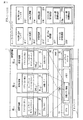
図1は本発明の一実施形態に係る仮想計算機システムの構成を示すブロック図である。図1に示す仮想計算機システムは、物理計算機(実計算機)1を用いて実現される。物理計算機1は、仮想計算機環境を提供するのに用いられるハードウェア(HW)10を備えている。HW10は、HW資源(物理資源)であるCPU(実CPU)11、メモリ(実メモリ)12及びネットワークデバイス(実ネットワークデバイス)13を含む。なお、図1では、ディスクドライブのような、物理計算機1に付属する、ネットワークデバイス13以外の入出力デバイスは省略されている。
Embodiments of the present invention will be described below with reference to the drawings.
FIG. 1 is a block diagram showing a configuration of a virtual machine system according to an embodiment of the present invention. The virtual computer system shown in FIG. 1 is realized using a physical computer (real computer) 1. The
ネットワークデバイス13は、物理計算機1の外部のネットワーク2に接続されている。ネットワークデバイス13は、ネットワーク2を介して物理計算機1と外部の物理デバイスとの間の通信を行う。
The
物理計算機1(のHW10)上では、仮想計算機マネージャ(VMM)20が動作する。VMM20は、仮想計算機システムの管理を行い、仮想計算機が動作する環境(仮想計算機環境)を構築する。更に具体的に述べるならば、VMM20は、物理計算機1のHW10を構成するCPU11、メモリ12及び、ネットワークデバイス13を含む各種の入出力デバイスのような物理資源(ハードウェアリソース)を制御すると共に当該物理資源の時間的、領域的な配分を管理することにより、複数の仮想計算機、例えば3台の仮想計算機30-1,30-2,30-3が動作する仮想計算機環境(仮想計算機実行環境)を構築する。
A virtual machine manager (VMM) 20 operates on the physical computer 1 (the HW 10). The VMM 20 manages the virtual machine system and constructs an environment (virtual machine environment) in which the virtual machine operates. More specifically, the VMM 20 controls physical resources (hardware resources) such as various input / output devices including the CPU 11, the
仮想計算機30-1,30-2,30-3上では、それぞれゲストOS31-1(#1),31-2(#2),31-3(#3)が動作する。更に具体的に述べるならば、ゲストOS31-1〜31-3は、それぞれ仮想計算機30-1〜30-3にロードされて、当該仮想計算機30-1〜30-3内の仮想CPUによって実行される。ゲストOS31-1,31-2,31-3は固有の識別子(ゲストOS識別子)を有する。本実施形態においてゲストOS31-1,31-2,31-3のゲストOS識別子は、それぞれ、1,2,3であるものとする。 On the virtual machines 30-1, 30-2, and 30-3, guest OSs 31-1 (# 1), 31-2 (# 2), and 31-3 (# 3) operate, respectively. More specifically, the guest OSs 31-1 to 31-3 are loaded into the virtual machines 30-1 to 30-3, respectively, and executed by the virtual CPUs in the virtual machines 30-1 to 30-3. The The guest OSs 31-1, 31-2, 31-3 have unique identifiers (guest OS identifiers). In this embodiment, the guest OS identifiers of the guest OSs 31-1, 31-2, and 31-3 are 1, 2, and 3, respectively.
VMM20はまた、ゲストOS31-1〜31-3(の後述するドライバ310-1〜310-3)からアクセス(参照/書き込み)可能な共有メモリ32を構築する。共有メモリ32は、HW10に含まれているメモリ12の記憶領域の一部(共有メモリ領域)32を用いて構築される仮想化されたメモリである。VMM20は、ゲストOS31-1〜31-3の間の通知のために割り込みを発生させるインタフェース(ゲストOS間割り込み配信インタフェース)を当該ゲストOS31-1〜31-3に提供する。
The VMM 20 also constructs a shared
ゲストOS31-1,31-2,31-3には、それぞれネットワークデバイスドライバ(以下、ドライバと略称する)310-1,310-2,310-3が付加されている。ドライバ310-1〜310-3は、それぞれ、ネットワークデバイス13をゲストOS31-1〜31-3が使用可能とするためのデバイスドライバであり、当該ゲストOS31-1〜31-3の一部として当該ゲストOS31-1〜31-3上で動作する。つまりゲストOS31-1〜31-3は、それぞれドライバ310-1〜310-3を含む。
Network device drivers (hereinafter abbreviated as drivers) 310-1, 310-2, 310-3 are added to the guest OSs 31-1, 31-2, 31-3, respectively. The drivers 310-1 to 310-3 are device drivers for enabling the guest OSs 31-1 to 31-3 to use the
ゲストOS31-1〜31-3は、それぞれがマスター(マスターゲストOS)となる機能を持つ。ドライバ310-1〜310-3は、それぞれゲストOS31-1〜31-3がマスターとして動作する場合、自身もマスターとして動作する。本実施形態において、ドライバ310-1,310-2,310-3は同等の機能を持つ。但し、ドライバ310-1〜310-3の間で本発明に直接関係しない一部の機能が異なっていても構わない。例えば、ドライバ310-1〜310-3のうちのいずれかで、マスターとなる機能が制限されていても構わない。 Each of the guest OSs 31-1 to 31-3 has a function of becoming a master (master guest OS). The drivers 310-1 to 310-3 themselves operate as masters when the guest OSs 31-1 to 31-3 operate as masters. In the present embodiment, the drivers 310-1, 310-2, 310-3 have equivalent functions. However, some functions not directly related to the present invention may be different between the drivers 310-1 to 310-3. For example, the master function may be limited by any of the drivers 310-1 to 310-3.
ドライバ310-i(i=1,2,3)は、HW(ハードウェア)割り込みハンドラ311及びSW(ソフトウェア)割り込みハンドラ312の2種類の割り込みハンドラを有する。HW割り込みハンドラ311は、ネットワークデバイス13によって発生される割り込み(HW割り込み)を処理する。SW割り込みハンドラ312は、ゲストOS間割り込み配信インタフェースによって発生される割り込み(ゲストOS31-1〜31-3の間の通知のための割り込み)を処理する。
The driver 310-i (i = 1, 2, 3) has two types of interrupt handlers, an HW (hardware) interrupt
ドライバ310-iは更に、open(オープン)処理部313、close(クローズ)処理部314、送信処理部315、受信処理部316、エラー割り込み処理部317、マスター権移行処理部318、ゲストOS排除処理部319を有する。マスター権移行処理部318は、マスター権委譲処理部318a及びマスター権取得処理部318bを含む。これらの各処理部の機能については後述する。
The driver 310-i further includes an
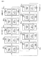
図2は、図1に示される共有メモリ32における領域の割り当て例を示す。共有メモリ32は、物理レジスタマップ領域321、特殊処理ステータス領域322、ゲストOS情報領域323及びDMAバッファ領域324を含む。共有メモリ32はまた、送信ディスクリプタチェーン領域325、受信ディスクリプタチェーン領域326及び他共有情報領域327を含む。
FIG. 2 shows an example of area allocation in the shared
物理レジスタマップ領域321は、ネットワークデバイス13に所属する物理レジスタの群をマップした領域である。物理レジスタマップ領域321によってマップされる物理レジスタの群は、初期化処理で設定が必要なレジスタ、及び割り込み要因レジスタを含む。物理レジスタマップ領域321にアクセスすることによって物理レジスタがアクセスされる。
The physical
特殊処理ステータス領域322は、ドライバ310-iが行うべき特殊な処理(特殊処理)が発生しているかを示すステータスを格納するのに用いられる。本実施形態において、特殊処理ステータス領域322を用いてステータスが管理される特殊処理は、共有メモリ32を初期化する処理、ネットワークの物理的切断(ネットワークケーブル抜けなどへの対応)処理、ネットワークの物理的接続処理を含む。これらの特殊処理は、共有メモリ32内の情報を使用して各ドライバ310-iで進めることができる処理であり、各ドライバ310-iで重複して実行されても問題の生じない処理である。本実施形態において、特殊処理ステータス領域322は、予め定められた特殊処理毎に、その処理が発生しているかをビットの状態で示すビットマップを格納する。ドライバ310-iは、ある特殊処理が発生しているかを確認するには、特殊処理ステータス領域322(に格納されているビットマップ)内の当該特殊処理に対応するビットを参照すればよい。
The special
ゲストOS情報領域323は、ネットワークデバイス13を使用している全てのゲストOSの情報と、マスターゲストOS情報とを格納するのに用いられる。ゲストOSの情報(ゲストOS情報)は、ゲストOS識別子、SW割り込み番号及びSW割り込み要因情報を含む。
The guest
ゲストOS識別子は、ネットワークデバイス13を現在使用しているゲストOSの識別子を示す。
SW割り込み番号は、ゲストOS識別子で示されるゲストOSに対して他のゲストOSから、ゲストOS間の通知機能(ゲストOS間割り込み配信インタフェース)によって割り込みを発生させる場合の割り込み配信先のゲストOSのSW割り込みハンドラ312を示す。
The guest OS identifier indicates the identifier of the guest OS that is currently using the
The SW interrupt number indicates the guest OS of the interrupt delivery destination when an interrupt is generated from another guest OS to the guest OS indicated by the guest OS identifier by the inter-guest OS notification function (inter-guest OS interrupt delivery interface). The SW interrupt
SW割り込み要因情報は、上記割り込みを発生させる場合の通知内容を表す情報。SW割り込み要因情報は例えばビットマップから構成される。配信先のゲストOSは、配信元のゲストOS(ゲストOS識別子で示されるゲストOS)のゲストOS間割り込み配信インタフェースから送信されたビットマップ形式のSW割り込み要因情報(の各ビットの状態)を参照することにより通知内容を判断する。 The SW interrupt factor information is information indicating the notification contents when the interrupt is generated. The SW interrupt factor information is composed of, for example, a bitmap. The distribution-destination guest OS refers to the bitmap-type SW interrupt factor information (the state of each bit) transmitted from the inter-guest OS interrupt distribution interface of the distribution-source guest OS (guest OS indicated by the guest OS identifier) To determine the notification contents.
ゲストOS情報は更に、付加的な情報として、タイムスタンプ、通信回数統計情報、ゲストOS優先度及びネットワークアドレスを含む。
タイムスタンプは、ゲストOS識別子で示されるゲストOSの最終動作時刻を示す。
The guest OS information further includes time stamp, communication count statistical information, guest OS priority, and network address as additional information.
The time stamp indicates the last operation time of the guest OS indicated by the guest OS identifier.
通信回数統計情報は、直近の通信回数を示す統計情報である。本実施形態において、通信回数統計情報には、1ディスクリプタチェーンサイクルの期間にゲストOSの使用したディスクリプタの数が用いられる。ディスクリプタチェーンサイクルについては後述する。 The communication count statistical information is statistical information indicating the most recent communication count. In the present embodiment, the number of descriptors used by the guest OS during one descriptor chain cycle is used for the communication count statistical information. The descriptor chain cycle will be described later.
ゲストOS優先度は、ゲストOS識別子で示されるゲストOSの実行優先度を示す。つまりゲストOS優先度は、VMM20が、ディスパッチされるべきゲストOSを選択する際に選定の基準(指標)とする値である。本実施形態では、ゲストOS優先度の値が大きいゲストOSほど、優先的にCPU11(CPU時間)が割り当てられる。
The guest OS priority indicates the execution priority of the guest OS indicated by the guest OS identifier. That is, the guest OS priority is a value used as a selection criterion (index) when the
ネットワークアドレスは、ネットワーク2を介しての通信のためにゲストOS識別子で示されるゲストOSに割り当てられる、IP(Internet Protocol)アドレスのようなネットワークアドレスである。
The network address is a network address such as an IP (Internet Protocol) address assigned to the guest OS indicated by the guest OS identifier for communication via the
マスターゲストOS情報は、マスタとして動作している(つまりマスター権を有している)ゲストOS(マスターゲストOS)を示す。ここでは、マスターゲストOS情報として、マスターゲストOSのゲストOS識別子が用いられる。 The master guest OS information indicates a guest OS (master guest OS) operating as a master (that is, having a master right). Here, the guest OS identifier of the master guest OS is used as the master guest OS information.
なお、図2に示されるゲストOS情報領域323には、便宜的に、ゲストOS識別子が「1」のゲストOS(つまりゲストOS31-1)のゲストOS情報のみが格納されている状態が示されている。しかし、ゲストOS情報領域323には、ネットワークデバイス13を共有する他のゲストOS31-2,31-3のゲストOS情報も格納されているものとする。
For convenience, the guest
DMAバッファ領域324は、ネットワークデバイス13が送受信データのDMA(Direct Memory Access)転送に使用するデータバッファ(以下、DMAバッファと称する)324aのための領域である。
The
送信ディスクリプタチェーン領域325は、送信ディスクリプタチェーン325aを格納するのに用いられる。送信ディスクリプタチェーン325aは、DMAバッファ324a内の領域(へのリンク)及びHW仕様に基づいた送信ディスクリプタを管理するためのディスクリプタ管理構造を有する。送信ディスクリプタチェーン325aに含まれる各送信ディスクリプタは、チェーンでリンクされている順にサイクリックに利用される。送信ディスクリプタチェーン325aを一巡するサイクルをディスクリプタチェーンサイクルと呼ぶ。
The transmission
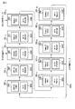
図3は、送信ディスクリプタチェーン325aの一例を示す。図3の例では、送信ディスクリプタチェーン325aは、送信ディスクリプタ325-1〜325-10を含む。本実施形態において送信ディスクリプタ325-1〜325-10はリング状のチェーンによりリンクされている。送信ディスクリプタ325-j(j=1〜10)は、ステータス部3251、ポインタ部3252及び利用ゲストOS情報部(図示せず)を含む。
FIG. 3 shows an example of the
ポインタ部3252は、送信されるべきデータが設定(格納)されているDMAバッファ324a内の領域を指し示すポインタを格納する。利用ゲストOS情報部は、当該利用ゲストOS情報部を含む送信ディスクリプタ325-jが、いずれのゲストOSによって参照(使用)中であるかを示す情報(例えばゲストOS識別子)を格納する。
The
ステータス部3251は、送信ディスクリプタ325-jのステータスを示す。送信ディスクリプタ325-jの取り得るステータスは、例えば、「empty」、「not ready」、「ready」及び「dma」の4種類である。
The
「empty」は、送信ディスクリプタ325-jが未使用の状態にあることを示す。
「not ready」は、送信ディスクリプタ325-jがデータ送信のために使用予定である(使用が予約されている)が、まだ送信されるべきデータの設定が終わっていない状態にあることを示す。
“Empty” indicates that the transmission descriptor 325-j is in an unused state.
“Not ready” indicates that the transmission descriptor 325-j is scheduled to be used for data transmission (reserved for use) but has not yet been set for data to be transmitted.
「ready」は、送信ディスクリプタ325-jがデータ送信のために使用予定であり、且つ送信されるべきデータの設定も終了している状態にあることを示す。 “Ready” indicates that the transmission descriptor 325-j is scheduled to be used for data transmission and the setting of data to be transmitted has been completed.
「dma」は送信ディスクリプタ325-jのポインタ部3252で指定されるデータの送信のためのDMA転送が実行中であることを示す。
“Dma” indicates that DMA transfer for transmission of data designated by the
送信ディスクリプタチェーン325aは、送信中先頭ポインタ、送信前先頭ポインタ及び空き先頭ポインタの3種類のポインタで管理される。これらのポインタは、任意の時点において、
送信中先頭ポインタ≦送信前先頭ポインタ≦空き先頭ポインタ
のような不等号で示される順番の位置関係(大きいほうが進行方向)にある送信ディスクリプタを指し示す。
The
This indicates a transmission descriptor in the positional relationship of the order indicated by an inequality sign such as the leading pointer during transmission ≦ the leading pointer before transmission ≦ the empty leading pointer (the larger is the traveling direction).
送信中先頭ポインタの指し示す位置から送信前先頭ポインタの指し示す位置の直前までには、ステータスが「dma」の送信ディスクリプタのみが存在する。図3の例では、送信ディスクリプタ325-3,325-4が、これに該当する。 Only a transmission descriptor having a status of “dma” exists between the position indicated by the leading pointer during transmission and immediately before the position indicated by the leading pointer before transmission. In the example of FIG. 3, transmission descriptors 325-3 and 325-4 correspond to this.
送信前先頭ポインタの指し示す位置から空き先頭ポインタの指し示す位置の直前までには、ステータスが「ready」の送信ディスクリプタとステータスが「not ready」の送信ディスクリプタとが混在し得る。図3の例では、送信ディスクリプタ325-5〜325-9が、これに該当する。 A transmission descriptor with a status of “ready” and a transmission descriptor with a status of “not ready” may coexist from the position indicated by the pre-transmission head pointer to immediately before the position indicated by the empty head pointer. In the example of FIG. 3, transmission descriptors 325-5 to 325-9 correspond to this.
空き先頭ポインタから先には、ステータスが「empty」の送信ディスクリプタのみが存在する。図3の例では、送信ディスクリプタ325-10,325-1,325-2が、これに該当する。
これら3種類のポインタは、ネットワークデバイス13によって操作される。
Only the transmission descriptor with the status “empty” exists beyond the empty head pointer. In the example of FIG. 3, transmission descriptors 325-10, 325-1, and 325-2 correspond to this.
These three types of pointers are operated by the
再び図2を参照すると、受信ディスクリプタチェーン領域326は、受信ディスクリプタチェーンを格納するのに用いられる。受信ディスクリプタチェーンは、DMAバッファ324a内の領域(へのリンク)及びHW仕様に基づいた受信ディスクリプタを管理するためのディスクリプタ管理構造を有する。受信ディスクリプタチェーンに含まれる各受信ディスクリプタは、送信ディスクリプタチェーン325aに含まれる上記各送信ディスクリプタと同様に、チェーンでリンクされている順にサイクリックに利用される。この受信ディスクリプタチェーンを一巡するサイクルもディスクリプタチェーンサイクルと呼ばれる。
Referring back to FIG. 2, the receive
図4は、受信ディスクリプタチェーンの一例を示す。図4の例では、受信ディスクリプタチェーンは、受信ディスクリプタ326-1〜326-10を含む。本実施形態において受信ディスクリプタ326-1〜326-10はリング状のチェーンによりリンクされている。受信ディスクリプタ326-j(j=1〜10)は、送信ディスクリプタ325-jと同様に、ステータス部3261、ポインタ部3262及び利用ゲストOS情報部(図示せず)を含む。
FIG. 4 shows an example of the reception descriptor chain. In the example of FIG. 4, the reception descriptor chain includes reception descriptors 326-1 to 326-10. In the present embodiment, the reception descriptors 326-1 to 326-10 are linked by a ring-shaped chain. Similarly to the transmission descriptor 325-j, the reception descriptor 326-j (j = 1 to 10) includes a
ポインタ部3262は、受信されるべきデータが設定されているDMAバッファ324a内の領域を指し示すポインタを格納する。利用ゲストOS情報部は、当該利用ゲストOS情報部を含む受信ディスクリプタ326-jが、いずれのゲストOSによって参照(使用)中であるかを示す情報(ゲストOS識別子)を格納する。
The
ステータス部3261は、受信ディスクリプタ326-jのステータスを示す。受信ディスクリプタ326-jの取り得るステータスは、例えば、「empty」、「received」及び「dma」の3種類である。
The
「empty」は、受信ディスクリプタ326-jが未使用の状態にあることを示す。
「received」は、受信ディスクリプタ326-jのポインタ部3262で指定されるDMAバッファ324a内の領域にデータを受信済みであるが、その旨をゲストOSが認識していない状態にあることを示す。
“Empty” indicates that the reception descriptor 326-j is in an unused state.
“Received” indicates that data has already been received in the area in the
「dma」は、受信ディスクリプタ326-jのポインタ部3262で指定されるDMAバッファ324a内の領域に受信データを一時格納するためのDMA転送が実行中であることを示す。
“Dma” indicates that a DMA transfer for temporarily storing received data in an area in the
受信ディスクリプタチェーンは、受信中先頭ポインタ、DMA中先頭ポインタ及び空き先頭ポインタの3種類のポインタで管理される。これらのポインタは、任意の時点において、
受信中先頭ポインタ≦DMA中先頭ポインタ≦空き先頭ポインタ
のような不等号で示される順番の位置関係(大きいほうが進行方向)にある受信ディスクリプタを指し示す。受信中先頭ポインタの指し示す位置からDMA中先頭ポインタの指し示す位置の直前までには、ステータスが「received」の受信ディスクリプタと「empty」の受信ディスクリプタとが混在する。図4の例では、受信ディスクリプタ326-3,326-4が、これに該当する。
The reception descriptor chain is managed by three types of pointers: a reception start pointer, a DMA start pointer, and an empty start pointer. These pointers can be
This indicates a reception descriptor that is in the positional relationship of the order indicated by an inequality sign such as a receiving top pointer ≦ a DMA starting pointer ≦ an empty head pointer (the larger one is the traveling direction). From the position pointed to by the leading pointer during reception to immediately before the position pointed to by the leading pointer during DMA, a reception descriptor with a status of “received” and a reception descriptor with an “empty” are mixed. In the example of FIG. 4, reception descriptors 326-3 and 326-4 correspond to this.
DMA中先頭ポインタの指し示す位置から空き先頭ポインタの指し示す位置の直前までには、ステータスが「dma」の受信ディスクリプタのみが存在する。図4の例では、受信ディスクリプタ326-5,326-6が、これに該当する。 Only a reception descriptor with a status of “dma” exists between the position indicated by the leading pointer in DMA and immediately before the position indicated by the empty leading pointer. In the example of FIG. 4, reception descriptors 326-5 and 326-6 correspond to this.
空き先頭ポインタから先には、ステータスが「empty」の受信ディスクリプタのみが存在する。図4の例では、受信ディスクリプタ326-7〜326-10,326-1,326-2が、これに該当する。
これら3種類のポインタは、ネットワークデバイス13によって操作される。
Only a reception descriptor with a status of “empty” exists beyond the empty head pointer. In the example of FIG. 4, the reception descriptors 326-7 to 326-10, 326-1, and 326-2 correspond to this.
These three types of pointers are operated by the
他共有情報領域327は、各ゲストOS31-i(i=1,2,3)のドライバ310-i間で共有すべき情報、例えば特殊処理で使用する必要がある情報を格納するのに用いられる。
The other shared
次に、上述の構成の仮想計算機システムの特徴について説明する。 Next, features of the virtual computer system having the above-described configuration will be described.
まず、図1の仮想計算機システムでは、ネットワークデバイス13を共有するゲストOS31-1〜31-3上でそれぞれドライバ310-1〜310-3が動作する。ドライバ310-1〜310-3の1つはマスターとして動作して、DMA処理や、DMA処理のためのネットワークデバイス13からの割り込みに対する処理など、当該ネットワークデバイス13の管理の主要な部分を取り扱う。
First, in the virtual machine system of FIG. 1, the drivers 310-1 to 310-3 operate on the guest OSs 31-1 to 31-3 sharing the
図1の仮想計算機システムの特徴は、ゲストOS31-1〜31-3上でそれぞれ動作するドライバ310-1〜310-3に共通して必要となる情報、及びゲストOS31-1〜31-3に固有のゲストOS情報のうち必要な部分を相互参照できるようにした点にある。この相互参照を可能とするために、VMM20によってゲストOS31-1〜31-3に提供される共有メモリ32が使用される。ゲストOS31-1〜31-3のそれぞれドライバ310-1〜310-3は共有メモリ32にアクセスする。
The virtual computer system of FIG. 1 is characterized by the information necessary for the drivers 310-1 to 310-3 operating on the guest OSs 31-1 to 31-3 and the guest OSs 31-1 to 31-3, respectively. A necessary part of the unique guest OS information can be cross-referenced. In order to enable this cross reference, the shared
共有メモリ32は、HW10に含まれているメモリ12に確保された共有メモリ領域120を用いて構築される仮想化されたメモリである。このため、共有メモリ32へのアクセスは、物理的にはメモリ12内の共有メモリ領域120へのアクセスによって実現される。
The shared
本実施形態ではまた、DMAバッファ324aも共有メモリ32に配置される。これにより、DMAバッファ324aも各ゲストOS31-1〜31-3から直接参照(アクセス)することが可能となり、従来は大きな問題であったデータコピーに伴うオーバヘッドを後述するように削減することができる。
In the present embodiment, the
また本実施形態では、マスターとなるゲストOSを変更可能とする仕組み、つまりマスターゲストOSが機能しなくなっても他のゲストOSがネットワークデバイス13を使用し続けることを可能とする仕組みが提供される。本実施形態では更に、効率的なネットワークデバイス13の使用を支援する仕組みも提供される。
In the present embodiment, a mechanism is provided that allows the guest guest OS to be changed, that is, a mechanism that allows other guest OSs to continue using the
以下、上述の特徴を有する仮想計算機システムにおけるゲストOSのドライバを中心とする動作について、「open(オープン)処理」、「送信処理」、「受信処理」及び「エラー割り込み処理」を例に順次説明する。 Hereinafter, operations centering on the driver of the guest OS in the virtual machine system having the above-described features will be sequentially described by taking “open (open) processing”, “transmission processing”, “reception processing”, and “error interrupt processing” as examples. To do.
[open処理]
まず、ゲストOSのドライバ(のopen処理部313)がネットワークデバイス13の使用を開始する際に実行する「open処理(ドライバのopen処理)」の手順について、当該ドライバがゲストOS31-1のドライバ310-1である場合を例に、図5のフローチャートを参照して説明する。
[Open processing]
First, regarding the procedure of “open processing (open processing of driver)” executed when the driver (open processing unit 313) of the guest OS starts using the
今、ゲストOS31-1から当該ゲストOS31-1のドライバ310-1に対して、「open要求」が与えられたものとする。するとドライバ310-1は、共有メモリ32の領域を探して、当該共有メモリ32の領域が存在するかを判定する(ステップS1)。
Assume that an “open request” is given from the guest OS 31-1 to the driver 310-1 of the guest OS 31-1. Then, the driver 310-1 searches for the area of the shared
もし、ステップS1の判定がYesであるならば、ドライバ310-1は、マスターとなっている別のゲストOSのドライバからの要求によって共有メモリ32の領域が確保されているとしてステップS8に進む。
If the determination in step S1 is Yes, the driver 310-1 proceeds to step S8, assuming that the area of the shared
これに対し、ステップS1の判定がNoであるならば、ドライバ310-1はVMM20に依頼して、共有メモリ32の領域を確保する(ステップS2)。つまりドライバ310-1は、VMM20により、HW10に含まれているメモリ12の記憶領域の一部を共有メモリ領域120として確保させることにより、共有メモリ32(仮想化された共有メモリメモリ)を構築させる。
On the other hand, if the determination in step S1 is No, the driver 310-1 requests the
次にドライバ310-1は、共有メモリ32を初期化するための初期化処理を行う(ステップS3)。この初期化処理は、共有メモリ32における領域321〜327の割り当て、物理レジスタマップ領域321に物理レジスタの群(ネットワークデバイス13に所属する物理レジスタの群)をマップする処理を含む。また、上記初期化処理は、特殊処理ステータス領域322に当該初期化処理が進行中であることを示すステータスを記録する処理を含む。ここでは、初期化処理が進行中であるかを示すビットがオンされる。以降、ドライバ310-1は、初期化処理の進捗状況を、例えば予め定められたタイミング毎に記録する。
Next, the driver 310-1 performs an initialization process for initializing the shared memory 32 (step S3). This initialization processing includes allocation of
またドライバ310-1は、ネットワークデバイス13を初期化する(ステップS4)。次にドライバ310-1は、ネットワークデバイス13からの割り込み(HW割り込み)の配信先を自身に設定する(ステップS5)。
The driver 310-1 initializes the network device 13 (step S4). Next, the driver 310-1 sets the distribution destination of the interrupt (HW interrupt) from the
次にドライバ310-1は、共有メモリ32のゲストOS情報領域323に、自身を含む(自身が動作している)ゲストOS31-1のゲストOS情報を書き込む(ステップS6)。即ちドライバ310-1は、ゲストOS31-1のゲストOS識別子、SW割り込みハンドラ312が使用するSW割り込み番号等を含む、ゲストOS31-1のゲストOS情報を、ゲストOS情報領域323に書き込む。また、ステップS6においてドライバ310-1は、マスターゲストOSがゲストOS31-1であることを示すマスターゲストOS情報をゲストOS情報領域323に登録する。そしてドライバ310-1は、共有メモリ32の特殊処理ステータス領域322に初期化処理が終了したことを記録して(ステップS7)、「open処理」を終了する。
Next, the driver 310-1 writes the guest OS information of the guest OS 31-1 including itself (in which it operates) in the guest
一方、ステップS1の判定がYesの場合、ドライバ310-1は、マスターとなっている別のゲストOSのドライバからの要求によって構築された共有メモリ32の特殊処理ステータス領域322を参照して当該別のゲストOSのドライバによる初期化処理(ステップS2〜S7)の進捗状況を確認し、当該初期化処理が継続していれば、当該初期化処理が終了するまで待つ(ステップS8)。そして初期化処理が終了すると、ドライバ310-1は、共有メモリ32のゲストOS情報領域323にゲストOS31-1に固有のゲストOS情報(自身のゲストOS情報)を書き込んで(ステップS9)、「open処理」を終了する。
On the other hand, if the determination in step S1 is Yes, the driver 310-1 refers to the special
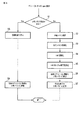
[送信処理]
次に、ゲストOSのドライバ(の送信処理部315)がネットワークデバイス13を通じてパケットをネットワーク2に送信する際に実行される「送信処理」の手順について、当該ドライバがゲストOS31-1のドライバ310-1である場合を例に、図6のフローチャートを参照して説明する。この「送信処理」において実行されるネットワークデバイス13へのパケットデータの転送には、DMAが用いられる。
[Transmission process]
Next, regarding the procedure of “transmission processing” executed when the driver of the guest OS (the transmission processing unit 315) transmits the packet to the
今、ゲストOS31-1から当該ゲストOS31-1のドライバ310-1に対して、「送信要求」が与えられたものとする。するとドライバ310-1は、共有メモリ32の送信ディスクリプタチェーン領域325における送信ディスクリプタチェーン325aから、空き先頭ポインタの指し示す送信ディスクリプタを先頭とする、送信に必要な数の送信ディスクリプタ325-j(図3の例では、送信ディスクリプタ325-jは送信ディスクリプタ325-10を含む)を確保する(ステップS11)。
Now, it is assumed that a “transmission request” is given from the guest OS 31-1 to the driver 310-1 of the guest OS 31-1. Then, the driver 310-1 transmits as many transmission descriptors 325-j (FIG. 3) as necessary for transmission from the
次にドライバ310-1は、確保した送信ディスクリプタ325-jのステータス(ステータス部3251に設定されているステータス情報の示すステータス)を「empty」から「not ready」に変更すると共に、確保した送信ディスクリプタ325-jの数だけ空き先頭ポインタを更新する(ステップS12)。つまりドライバ310-1は、確保した送信ディスクリプタ325-jの数だけ空き先頭ポインタの指し示す位置を移動する。 Next, the driver 310-1 changes the status of the secured transmission descriptor 325-j (the status indicated by the status information set in the status part 3251) from “empty” to “not ready”, and also secures the secured transmission descriptor. The empty head pointer is updated by the number of 325-j (step S12). That is, the driver 310-1 moves the position indicated by the empty head pointer by the number of transmission descriptors 325-j secured.
次にドライバ310-1は、確保した送信ディスクリプタ325-jを(当該ドライバ310-1を含む)ゲストOS31-1が使用していることを示す情報を、当該ディスクリプタ325-jに追加する。上記ステップS11〜S13は、各ゲストOSのドライバ間で排他的に実行される必要がある。この制御には、共有メモリを使用する際に従来から用いられる一般的な排他制御手法が適用可能である。この排他制御については、以降の手順でも同様の条件が必要となる箇所があるが、説明を省略する。 Next, the driver 310-1 adds information indicating that the reserved transmission descriptor 325-j is being used by the guest OS 31-1 (including the driver 310-1) to the descriptor 325-j. The above steps S11 to S13 need to be executed exclusively between the drivers of each guest OS. For this control, a general exclusive control method conventionally used when using a shared memory can be applied. About this exclusive control, although there are places where the same conditions are necessary in the subsequent procedures, the description is omitted.
次にドライバ310-1は、ゲストOS31-1から要求されたパケットの送信のために、次のように送信ディスクリプタ325-jの準備を行う(ステップS14)。まずドライバ310-1は、送信ディスクリプタ325-jのポインタ部3252に格納されているポインタに基づいて共有メモリ32上のDMAバッファ324a内の領域に直接アクセスすることにより、送信されるべきパケットのデータを書き込む。ドライバ310-1は、このデータの書き込み(つまり送信の準備)が完了した送信ディスクリプタ325-jのステータスを「not ready」から「ready」に変更する。
Next, the driver 310-1 prepares the transmission descriptor 325-j as follows in order to transmit the packet requested from the guest OS 31-1 (step S14). First, the driver 310-1 directly accesses the area in the
本実施形態おいて、DMA転送はマスターゲストOSが管理する。そこでドライバ310-1は、当該ドライバ310-1を含む(当該ドライバ310-1動作している)ゲストOS31-1がマスターゲストOSであるかを判定する(ステップS15)。 In this embodiment, the DMA transfer is managed by the master guest OS. Therefore, the driver 310-1 determines whether the guest OS 31-1 including the driver 310-1 (operating the driver 310-1) is the master guest OS (step S15).
もし、ゲストOS31-1がマスターゲストOSでないならば(ステップS15がNo)、ドライバ310-1はマスターゲストOS(のドライバ)にSW割り込みによる通知を行って、送信のためのDMA転送を要求する(ステップS16)。即ちドライバ310-1はマスターゲストOS(のドライバ)に、送信のためのDMA要求の割り込み(送信DMA要求割り込み)を行う。マスターゲストOS(のドライバ)への割り込み配信先は、共有メモリ32のゲストOS情報領域323を参照することによって知ることができる。ドライバ310-1は、ステップS16を実行すると、送信処理を終了する。
If the guest OS 31-1 is not the master guest OS (No in step S15), the driver 310-1 notifies the master guest OS (driver) by SW interrupt and requests a DMA transfer for transmission. (Step S16). That is, the driver 310-1 issues a DMA request interrupt for transmission (transmission DMA request interrupt) to the master guest OS (driver). The interrupt delivery destination to the master guest OS (driver) can be known by referring to the guest
上述のように、本実施形態では、ゲストOS間の通知にSW割り込みが使用される。しかし、VMM20が提供するゲストOS間の通知手段であれば、SW割り込み以外の手段を用いても構わない。本実施形態では、複数の用途でゲストOS間の通知にSW割り込みが使用される。そこで本実施形態では、割り込み配信先が用途別に設定され、また、割り込み要因を示す仮想の割り込み要因レジスタが共有メモリ32内に配置される構成とすることによって、割り込み要因の種別を対象のゲストOSが認識できるようになっているものとする。
As described above, in this embodiment, the SW interrupt is used for notification between guest OSes. However, as long as it is a notification means between guest OSes provided by the
一方、ステップS15で、ドライバ310-1を含むゲストOS31-1がマスターゲストOSであると判定された場合、つまり送信要求元のゲストOS31-1がマスターゲストOSである場合(ステップS15がYes)、ドライバ310-1はステップS17に進む。また、ゲストOS31-1がマスターゲストOSであり、且つ当該ゲストOS31-1に、他のゲストOSからの送信要求に従って当該他のゲストOSのドライバから送信DMA要求割り込み(送信要求割り込み)が入った場合にも、ドライバ310-1はステップS17に進む。 On the other hand, if it is determined in step S15 that the guest OS 31-1 including the driver 310-1 is the master guest OS, that is, if the guest OS 31-1 that is the transmission request source is the master guest OS (Yes in step S15). Then, the driver 310-1 proceeds to step S17. In addition, the guest OS 31-1 is the master guest OS, and the guest OS 31-1 receives a transmission DMA request interrupt (transmission request interrupt) from the driver of the other guest OS according to the transmission request from the other guest OS. Even in this case, the driver 310-1 proceeds to step S17.
ステップS17においてドライバ310-1は、ネットワークデバイス13に対するDMA処理を開始する。具体的には、ドライバ310-1は、送信前先頭ポインタで指し示される送信ディスクリプタチェーン325a内の位置からステータスが「ready」である連続する送信ディスクリプタの分だけ、ネットワークデバイス13に対してDMA要求を発行する。ここで、複数のゲストOSが送信ディスクリプタを確保して送信のための準備中である可能性もあるため、送信前先頭ポインタの指し示す位置から空き先頭ポインタの指し示す位置の直前までには、ステータスが「not ready」の送信ディスクリプタとステータスが「ready」の送信ディスクリプタとが混在している可能性がある。ステップS17においてドライバ310-1は、DMA処理が開始された送信ディスクリプタのステータスを「dma」に変更し、送信前先頭ポインタを当該DMA処理が開始された送信ディスクリプタの数の分だけ進める。
In step S <b> 17, the driver 310-1 starts DMA processing for the
ドライバ310-1からのDMA要求に応じてネットワークデバイス13によって実行されるDMA転送が終了すると、当該ネットワークデバイス13からドライバ310-1(マスターゲストOS31-1のドライバ310-1)に、DMA転送終了(DMA終了)がHW割り込みによって通知される。ドライバ310-1は、このDMA終了のHW割り込みに応じて、送信中先頭ポインタの指し示す位置から始まる送信終了した送信ディスクリプタのステータスを「empty」に変更し、変更の対象となった送信ディスクリプタの数の分だけ、当該送信中先頭ポインタを更新する(ステップS18)。このステップS18においてドライバ310-1は、変更の対象となった各送信ディスクリプタの利用ゲストOS情報部に格納されている、当該ディスクリプタを参照(使用)中のゲストOSを示す情報をクリアする。
When the DMA transfer executed by the
ドライバ310-1(マスターゲストOS31-1のドライバ310-1)は、ステップS18を実行すると、空き先頭ポインタと送信前先頭ポインタとが一致しているかを判定する(ステップS19)。もし、空き先頭ポインタと送信前先頭ポインタとが一致していなければ(ステップS19がNo)、ドライバ310-1は、DMA要求が未発行の送信ディスクリプタがあるはずであると判断する。この場合、ドライバ310-1は、ネットワークデバイス13に対して再びDMA要求を発行するために、ステップS17に戻る。
When the driver 310-1 (the driver 310-1 of the master guest OS 31-1) executes step S18, the driver 310-1 determines whether or not the empty head pointer matches the head pointer before transmission (step S19). If the free head pointer and the pre-transmission head pointer do not match (No in step S19), the driver 310-1 determines that there should be a transmission descriptor for which a DMA request has not been issued. In this case, the driver 310-1 returns to step S17 in order to issue a DMA request to the
これに対し、空き先頭ポインタと送信前先頭ポインタとが一致しているならば(ステップS19がYes)、ドライバ310-1は、DMA要求が未発行の送信ディスクリプタがないとして送信処理を終了する。 On the other hand, if the empty head pointer matches the head pointer before transmission (Yes in step S19), the driver 310-1 terminates the transmission process on the assumption that there is no transmission descriptor for which a DMA request has not been issued.
[受信処理]
次に、ゲストOSのドライバ(の受信処理部316)がネットワークデバイス13を通じてパケットを受信する際に実行される「受信処理」の手順について、当該ドライバがゲストOS31-1のドライバ310-1である場合を例に、図7のフローチャートを参照して説明する。
[Receive processing]
Next, regarding the procedure of “reception processing” executed when the driver of the guest OS (the reception processing unit 316) receives the packet through the
ネットワークデバイス13は、ネットワーク2から自身が受信すべきパケットを検知すると、空きの受信ディスクリプタ326-jのポインタ部3252で指定されるDMAバッファ324a内の領域へ検知されたパケットをDMA転送する動作(受信DMA動作)を開始する(ステップS21)。DMAバッファ324a内の領域の使用順序は例えばHWを用いた設定によって予め指定することができる。本実施形態では、DMAバッファ324a内の領域の使用順序は、受信ディスクリプタチェーンの順番通りになるよう設定されている。
When the
さて、ネットワークデバイス13による上述の受信DMA動作(ステップS21)が完了したものとする。即ち、ネットワークデバイス13がネットワーク2からパケットを受信し、その受信されたパケットを、受信ディスクリプタチェーンに従って空きの受信ディスクリプタ326-jのポインタ部3252で指定されるDMAバッファ324a内の領域へDMA転送する受信DMA動作(ステップS21)が完了したものとする。この場合、ネットワークデバイス13はマスターゲストOSにHW割り込みを発行する(ステップS22)。ここでは、マスターゲストOSはゲストOS31-1であるものとする。
Now, it is assumed that the above-described reception DMA operation (step S21) by the
マスターゲストOS31-1のドライバ310-1は、ネットワークデバイス13からのHW割り込みを受け付けると、DMA中先頭ポインタの指し示す受信ディスクリプタチェーンの位置から、受信DMA(受信データを一時格納するためのDMA転送)が完了した受信ディスクリプタ326-jを調べる(ステップS23)。このステップS23においてドライバ310-1は、受信DMAが完了した受信ディスクリプタ326-jのステータスを「empty」から「received」に更新すると共に、DMA中先頭ポインタを更新する。また、ステップS23においてドライバ310-1は、受信DMAが完了した受信ディスクリプタ326-jの内容(受信ディスクリプタ326-jで示される受信データ)を必要としているゲストOSを特定する。即ちドライバ310-1は、ゲストOS情報領域323に格納されている各ゲストOSのゲストOS情報の中から、受信パケットに含まれている宛先ネットワークアドレスに一致するネットワークアドレスを含むゲストOS情報を選択し、当該選択されたゲストOS情報に含まれているゲストOS識別子から上述の受信ディスクリプタ326-jの内容を必要とするゲストOSを特定する。
When the driver 310-1 of the master guest OS 31-1 accepts the HW interrupt from the
ドライバ310-1は、受信DMAが完了した受信ディスクリプタ326-jをいずれのゲストOSが参照すべきかを示す情報を、当該受信ディスクリプタ326-jの利用ゲストOS情報部に設定する。もし、ネットワークデバイス13によってネットワーク2から受信されたパケットがブロードキャストパケットのような、複数のゲストOSによって参照されるべきパケットである場合、当該複数のゲストOSの情報が、該当する受信ディスクリプタ326-jの利用ゲストOS情報部に設定される。
The driver 310-1 sets information indicating which guest OS should refer to the reception descriptor 326-j for which reception DMA has been completed in the used guest OS information section of the reception descriptor 326-j. If the packet received from the
ゲストOS31-1のドライバ310-1は、受信ディスクリプタ326-jの情報を必要とするゲストOSに対して、受信DMAの完了をSW割り込みによって通知する(ステップS24)。ここで、ドライバ310-1からのSW割り込みを受けたゲストOSがゲストOS31-2及び31-3であるものとする。 The driver 310-1 of the guest OS 31-1 notifies the guest OS that needs the information of the reception descriptor 326-j of the completion of reception DMA by an SW interrupt (step S24). Here, it is assumed that the guest OSs that have received the SW interrupt from the driver 310-1 are the guest OSs 31-2 and 31-3.
ゲストOS31-1からのSW割り込みを受けたゲストOS31-2及び31-3のそれぞれドライバ310-2及び310-3は、自身に割り当てられた受信ディスクリプタ326-jを参照して受信に必要な処理を行う(ステップS25)。この受信に必要な処理は、受信ディスクリプタ326-jのポインタ部3262によって指し示されるDMAバッファ324a内の領域のデータを、ゲストOS31-2及び及び31-3に固有の記憶領域に転送する処理を含む。ドライバ310-2及び310-3は、受信に必要な処理を完了して、受信ディスクリプタ326-jを参照する必要がなくなると、当該ディスクリプタ326-jからそれぞれゲストOS31-2及び31-3に関する情報を削除する。
The drivers 310-2 and 310-3 of the guest OSs 31-2 and 31-3 that have received the SW interrupt from the guest OS 31-1 refer to the reception descriptor 326-j assigned thereto and perform processing necessary for reception. Is performed (step S25). The process necessary for this reception is a process of transferring the data in the area in the
マスターゲストOS31-1のドライバ310-1は、受信ディスクリプタ326-jから当該ディスクリプタ326-jを参照すべきゲストOS31-2及び31-3に関する情報が全て削除されると、当該ディスクリプタ326-jのステータスを「received」から「empty」に更新する(ステップS26)。つまりドライバ310-1は、受信ディスクリプタ326-jを参照する必要のあった全てのゲストOSにとって、もはや当該ディスクリプタ326-jを参照する必要がなくなると、当該ディスクリプタ326-jのステータスを「empty」に更新する。ステップS26においてドライバ310-1は、受信中先頭ポインタの指し示す受信ディスクリプタ326-jのステータスが「empty」に更新されたならば、当該受信中先頭ポインタを1受信ディスクリプタ分だけ進める。 When all the information on the guest OSs 31-2 and 31-3 that should refer to the descriptor 326-j is deleted from the reception descriptor 326-j, the driver 310-1 of the master guest OS 31-1 deletes the descriptor 326-j. The status is updated from “received” to “empty” (step S26). That is, the driver 310-1 sets the status of the descriptor 326-j to “empty” when it is no longer necessary to refer to the descriptor 326-j for all the guest OSs that need to reference the reception descriptor 326-j. Update to In step S26, if the status of the reception descriptor 326-j pointed to by the receiving head pointer is updated to “empty”, the driver 310-1 advances the receiving head pointer by one receiving descriptor.
[エラー割り込み処理]
次に、ネットワークデバイス13での動作でエラーが発生した場合に実行される「エラー割り込み処理」の手順について、ゲストOS31-1がマスターゲストOSである場合を例に、図8のフローチャートを参照して説明する。
[Error interrupt processing]
Next, with regard to the procedure of “error interrupt processing” executed when an error occurs in the operation of the
今、ネットワークデバイス13での動作でエラーが発生したものとする。この場合、ネットワークデバイス13はマスターゲストOS31-1のドライバ310-1にエラー発生を通知するためのHW割り込みを発行する(ステップS30)。
It is assumed that an error has occurred in the operation of the
ドライバ310-1(のHW割り込みハンドラ311)は、ネットワークデバイス13からHW割り込み(ステップS30)を受けると、共有メモリ32の物理レジスタマップ領域321にマップされた、当該HW割り込みの要因を示す割り込み要因レジスタ(例えば当該ネットワークデバイス13のエラーステータスを示すエラーステータスレジスタ)を参照することによって当該HW割り込みの要因となったエラーの種類を識別する(ステップS31)。このステップS31においてドライバ310-1(のエラー割り込み処理部317)は、識別されたエラーに対応する処理(エラー処理)が必要ならば、共有メモリ32の特殊処理ステータス領域322に格納されているビットマップ中の当該エラー処理に対応するビットを、エラー処理が開始されていることを示す状態に設定する。つまりドライバ310-1(マスターゲストOS31-1のドライバ310-1)は特殊処理ステータス領域322に、識別されたエラーに対応する処理(エラー処理)が開始されていることを示すステータス(特殊処理ステータス)を設定する(ステップS31)。
When the driver 310-1 (the HW interrupt handler 311) receives the HW interrupt (step S30) from the
次にマスターゲストOS31-1のドライバ310-1(のエラー割り込み処理部317)は、他のゲストOS31-2及び31-3のそれぞれドライバ310-2及び310-3に対し、エラー処理を開始したことを、SW割り込みを使用して通知する(ステップS32)。その後、マスターゲストOS31-1のドライバ310-1は、エラー処理が終了すると、共有メモリ32の特殊処理ステータス領域322に格納されているビットマップ中の当該処理に対応するビットの状態を、処理が行われていないことを示す状態に切り替える。つまりドライバ310-1は、特殊処理ステータス領域322に設定されている、エラー処理が開始されていることを示すステータスを解除する(ステップS33)。
Next, the driver 310-1 (the error interrupt processing unit 317) of the master guest OS 31-1 started error processing for the drivers 310-2 and 310-3 of the other guest OSs 31-2 and 31-3, respectively. This is notified using the SW interrupt (step S32). After that, when the error processing is completed, the driver 310-1 of the master guest OS 31-1 processes the bit status corresponding to the processing in the bitmap stored in the special
一方、マスターゲストOS31-1以外のゲストOS31-2及び31-3のそれぞれドライバ310-2及び310-3(のエラー割り込み処理部317)は、ドライバ310-1からエラー処理の開始を通知するSW割り込み(ステップS32)を受けると、現在実行中の処理を中断または中止するために必要な処理を、当該エラーの種類に応じて行う(ステップS41)。 On the other hand, the drivers 310-2 and 310-3 (the error interrupt processing unit 317) of the guest OSs 31-2 and 31-3 other than the master guest OS 31-1 notify the start of error processing from the driver 310-1. When an interrupt (step S32) is received, a process necessary for interrupting or canceling the currently executing process is performed according to the type of the error (step S41).
次にドライバ310-2及び310-3は、それぞれ共有メモリ32の特殊処理ステータス領域322のステータスを監視し、エラー処理が開始されていることを示すステータスが解除されていることを確認したならば、つまりエラー処理が終了したことを確認したならば、通常の処理に復帰する(ステップS42)。
Next, the drivers 310-2 and 310-3 monitor the status of the special
以上、本実施形態において適用される、ゲストOS31-i(i=1,2,3)のドライバ310-i(に設けられたopen処理部313、送信処理部315、受信処理部316及びエラー割り込み処理部317)が有する4つの基本的な機能、つまり「open処理機能」、「送信処理機能」、「受信処理機能」及び「エラー割り込み処理機能」について詳述した。これらの機能、特に「送信処理機能」及び「受信処理機能」により、DMAバッファのデータのコピーによるオーバヘッドを除くことができる。
As described above, the
さて本実施形態では、ドライバ310-iに、「マスター権の委譲処理機能」及び「マスター権の取得処理機能」(をそれぞれ有するマスター権委譲処理部318a及びマスター権取得処理部318b)が追加されている。以下、「マスター権の委譲処理」及び「マスター権の取得処理」について順次説明する。
In this embodiment, a “master right delegation processing function” and a “master right acquisition processing function” (a master right
[マスター権の委譲処理]
「マスター権の委譲処理」とは、マスターゲストOSが自律的に、マスター権を他のゲストOSへと移すための処理である。以下、「マスター権の委譲処理」について、ゲストOS31-1がマスターゲストOSである場合を例に、図9のフローチャートを参照して説明する。
[Delegation of master rights]
The “master right delegation process” is a process for the master guest OS to autonomously transfer the master right to another guest OS. The “master right delegation process” will be described below with reference to the flowchart of FIG. 9 by taking as an example the case where the guest OS 31-1 is the master guest OS.
マスターゲストOS31-1のドライバ310-1(のマスター権委譲処理部318a)は、マスター権の委譲が必要となった場合、現在ネットワークデバイス13を共有している他のゲストOSの中から、マスター権が委譲されるべきゲストOSを1つ選択する(ステップS51)。ここでは、ゲストOS31-2が選択されたものとする。ステップS51において、マスターゲストOS31-1のドライバ310-1は、SW割り込みを使用して、マスターゲストOS31-1以外の全てのゲストOS(ここでは、ゲストOS31-2及び32-3)に、ゲストOS31-1からゲストOS31-2へのマスターゲストOS変更を通知する。
The driver 310-1 of the master guest OS 31-1 (the master right
SW割り込みによってマスターゲストOS変更の通知を受けたゲストOSのうち、マスター権が委譲されるゲストOS31-2のドライバ310-2は、共有メモリ32のゲストOS情報領域323のマスターゲストOSに関連する情報を当該ゲストOS31-2を示すように更新する(ステップS52)。
Of the guest OSs notified of the change of the master guest OS by the SW interrupt, the driver 310-2 of the guest OS 31-2 to which the master right is transferred is related to the master guest OS in the guest
マスターゲストOS変更の通知を受けたゲストOSのうち、マスター権が委譲されるゲストOS(新マスターゲストOS)31-2のドライバ310-2は、ネットワークデバイス13からのHW割り込み先がゲストOS31-2(ドライバ310-2)自身になるように設定を変更する(ステップS61)。もし、マスターゲストOS変更を通知したゲストOS(旧マスターゲストOS)31-1が特殊処理を実行中であったならば、新マスターゲストOS31-2は、共有メモリ32の特殊処理ステータス領域322を参照して当該特殊処理を途中から引き継ぐ(ステップS62)。
Of the guest OSs that have received the notification of the change of the master guest OS, the driver 310-2 of the guest OS (new master guest OS) 31-2 to which the master right is transferred has the HW interrupt destination from the
[マスター権の取得処理]
「マスター権の取得処理」とは、マスター以外のゲストOSが自身へマスター権を移すための処理、つまりマスター以外のゲストOSがマスター権を取得するための処理である。以下、「マスター権の取得処理」について、ゲストOS31-1がマスターゲストOSであり、ゲストOS31-2がマスター権を取得しようとするゲストOSである場合を例に、図10のフローチャートを参照して説明する。
[Master right acquisition processing]
The “master right acquisition process” is a process for a guest OS other than the master to transfer the master right to itself, that is, a process for a guest OS other than the master to acquire the master right. Hereinafter, with respect to the “master right acquisition process”, the guest OS 31-1 is the master guest OS, and the guest OS 31-2 is the guest OS to acquire the master right, with reference to the flowchart of FIG. I will explain.
ゲストOS31-2のドライバ310-2(のマスター権取得処理部318b)は、当該ゲストOS31-2がマスター権を取得しようとする場合、その旨を当該ゲストOS31-2以外の、マスターゲストOS31-1を含む全てのゲストOS(ここでは、ゲストOS31-1及び32-3)に対してSW割り込みを使用して通知する(ステップS71)。この通知により、ゲストOS31-2以外のゲストOSでのマスターゲストOSに関する処理が抑止され、ゲストOS31-2はマスター権を排他的に取得することが可能となる。 When the guest OS 31-2 wants to acquire the master right, the driver 310-2 (the master right acquisition processing unit 318b) of the guest OS 31-2 notifies the master guest OS 31- other than the guest OS 31-2. 1 is notified to all guest OSs (here, guest OSs 31-1 and 32-3) including 1 using the SW interrupt (step S71). By this notification, the processing related to the master guest OS in the guest OS other than the guest OS 31-2 is suppressed, and the guest OS 31-2 can acquire the master right exclusively.
ゲストOS31-2のドライバ310-2はステップS71を実行すると、共有メモリ32のゲストOS情報領域323のマスターゲストOS情報を当該ゲストOS31-2を示すように更新する(ステップS72)。これによりゲストOS31-2はマスター権を取得して、新たにマスターゲストOS(新マスターゲストOS)となる。
When executing the step S71, the driver 310-2 of the guest OS 31-2 updates the master guest OS information in the guest
ゲストOS31-2のドライバ310-2は、ネットワークデバイス13からのHW割り込み先がゲストOS31-2自身になるように設定を変更する(ステップS73)。
The driver 310-2 of the guest OS 31-2 changes the setting so that the HW interrupt destination from the
もし、ゲストOS(新マスターゲストOS)31-2がマスター権を取得するまでマスターであったゲストOS(旧マスターゲストOS)31-1が特殊処理を実行中であったならば、新マスターゲストOS31-2は、共有メモリ32の特殊処理ステータス領域322を参照して当該特殊処理を途中から引き継ぐ(ステップS74)。
If the guest OS (old master guest OS) 31-1 that was the master until the guest OS (new master guest OS) 31-2 obtains mastership is executing special processing, the new master guest The OS 31-2 refers to the special
[close処理]
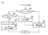
本実施形態では、ゲストOSのドライバ(のclose処理部314)がネットワークデバイス13の使用を終了する際に実行される「close処理(ドライバのclose処理)」で、上述の「マスター権の委譲処理」が利用される。以下、この「close(クローズ)処理」の手順について、ゲストOS31-1のドライバ310-1がネットワークデバイス13の使用を終了する場合を例に、図11のフローチャートを参照して説明する。
[Close processing]
In the present embodiment, the above-mentioned “master right delegation process” is performed in the “close process (driver close process)” executed when the driver (close process unit 314) of the guest OS terminates the use of the
今、ゲストOS31-1から当該ゲストOS31-1のドライバ310-1に対して、「close要求」が与えられたものとする。するとドライバ310-1(のclose処理部314)は、当該ドライバ310-1を含むゲストOS31-1がマスターゲストOSであるかを判定する(ステップS81)。もし、ゲストOS31-1がマスターゲストOSでないならば(ステップS81がNo)、ドライバ310-1は後述するステップS84に進む。 Now, it is assumed that a “close request” is given from the guest OS 31-1 to the driver 310-1 of the guest OS 31-1. Then, the driver 310-1 (the close processing unit 314) determines whether the guest OS 31-1 including the driver 310-1 is a master guest OS (step S81). If the guest OS 31-1 is not the master guest OS (No in step S81), the driver 310-1 proceeds to step S84 described later.
一方、ゲストOS31-1がマスターゲストOSであるならば(ステップS81がYes)、ドライバ310-1は、他にネットワークデバイス13を共有しているゲストOS(他のゲストOS)が存在するかを判定する(ステップS82)。
On the other hand, if the guest OS 31-1 is the master guest OS (Yes in step S81), the driver 310-1 determines whether there is another guest OS (other guest OS) sharing the
もし、ステップS82の判定がYesであるならば、即ちゲストOS31-1がマスターゲストOSで、且つ他にネットワークデバイス13を共有しているゲストOSがあるならば、当該ゲストOS31-1のドライバ310-1(のclose処理部314)は(マスター権委譲処理部318aを用いて)上述の「マスター権の委譲処理」を行う(ステップS83)。そしてドライバ310-1はステップS84に進む。
If the determination in step S82 is Yes, that is, if the guest OS 31-1 is the master guest OS and there is another guest OS sharing the
ステップS84においてドライバ310-1(旧マスターゲストOS31-1のドライバ310-1)は、共有メモリ32から当該ドライバ310-1を含むゲストOS(旧マスターゲストOS)31-1に関連する情報を削除する。このステップS84での処理は、ドライバ310-1が確保・参照していた各ディスクリプタの解放を含む。ドライバ310-1はステップS84を実行すると、「close処理」を終了する。
In step S84, the driver 310-1 (the driver 310-1 of the old master guest OS 31-1) deletes information related to the guest OS (old master guest OS) 31-1 including the driver 310-1 from the shared
一方、ステップS82の判定がNoであるならば、即ちゲストOS31-1がマスターゲストOSで、且つ他にネットワークデバイス13を共有しているゲストOSがないならば、当該ゲストOS31-1のドライバ310-1は、ネットワークデバイス13を停止させるための処理(ネットワークデバイス終了処理)を行う(ステップS85)。そしてドライバ310-1は、VMM20により共有メモリ32(共有メモリ領域120)を解放させて(ステップS86)、「close処理」を終了する。
On the other hand, if the determination in step S82 is No, that is, if the guest OS 31-1 is the master guest OS and there is no other guest OS sharing the
このような「close処理」により、たとえマスターゲストOSのドライバがcloseされても、つまりマスターゲストOSがネットワークデバイス13の使用を終了しても、他のゲストOSで運用を続けることが可能となる。
By such “close processing”, even if the driver of the master guest OS is closed, that is, even if the master guest OS ends the use of the
<相互監視に基づいたゲストOSの排除>
本実施形態のように複数のゲストOSのドライバ(ネットワークデバイスドライバ)が協調して動作する場合、次のような問題が生じる可能性がある。例えば、あるゲストOSが「panic」或いは「hang」と呼ばれるような動作不能な状態に陥った場合に、ネットワークデバイス13のHW仕様によってはそのゲストOSが使用しているディスクリプタの処理が進まなくなって、結果として送受信の処理を進めなくなる可能性がある。また、マスターゲストOSが動作不能になった場合は、通信自体を行うことができなくなってしまう。
<Elimination of guest OS based on mutual monitoring>
When a plurality of guest OS drivers (network device drivers) operate in a coordinated manner as in this embodiment, the following problem may occur. For example, when a guest OS falls into an inoperable state called “panic” or “hang”, processing of descriptors used by the guest OS may not proceed depending on the HW specification of the
そこで本実施形態では、ゲストOS31-1〜31-3が正常に動作しているかを、当該ゲストOS31-1〜31-3のドライバ310-1〜310-3が相互に監視する仕組みと、正常に動作していないと判断されたゲストOSをネットワークデバイス13の共有状態から強制的に排除する仕組みとが用意される。この2つの仕組みにより、ゲストOS(例えばマスターゲストOS)が動作不能になっても、残りのゲストOSによって運用が続けられる。
Therefore, in the present embodiment, the mechanism in which the drivers 310-1 to 310-3 of the guest OSs 31-1 to 31-3 mutually monitor whether the guest OSs 31-1 to 31-3 are operating normally, A mechanism is provided for forcibly removing a guest OS that has been determined not to be operating from the shared state of the
正常に動作していないゲストOSを検出する手法は種々考えられる。ここでは以下に示す簡単な検出手法が適用されるものとする。
まず、共有メモリ32(共有メモリ領域120)に、ゲストOS31-1〜31-3に共通のカウンタ(カウンタ領域)が用意される。
There are various methods for detecting a guest OS that is not operating normally. Here, the following simple detection method is applied.
First, a counter (counter area) common to the guest OSs 31-1 to 31-3 is prepared in the shared memory 32 (shared memory area 120).
ゲストOS31-1〜31-3のドライバ310-1〜310-3は、それぞれ特定のタイミングで上記共通のカウンタをカウントアップし、そのカウントアップ後の当該カウンタの値(カウンタ値)を、共有メモリ32のゲストOS情報領域323に格納される自身のゲストOS情報内に保持する。なお、上記特定のタイミングを、ゲストOS内のタイマで管理しても良いし、通信時における特定の処理の機会としても良い。
The drivers 310-1 to 310-3 of the guest OSs 31-1 to 31-3 respectively count up the common counter at a specific timing, and use the counter value (counter value) after the count-up as a shared memory. It is held in its own guest OS information stored in the 32 guest
ゲストOS31-1〜31-3のドライバ310-1〜310-3は、それぞれ他のゲストOSによって当該他のゲストOSのゲストOS情報に保持されているカウンタ値(つまり他のゲストOSのカウンタ値)を監視する。そしてドライバ310-1〜310-3は、他のゲストOSのカウンタ値と共通のカウンタの値との差が閾値を超えていたなら、当該他のゲストOSにSW割り込みを配信する。なお、上記の監視のタイミングを、ゲストOS内のタイマで管理しても良いし、通信時における特定の処理の機会としても良い。 The drivers 310-1 to 310-3 of the guest OSs 31-1 to 31-3 are counter values held in the guest OS information of the other guest OSs by the other guest OSs (that is, counter values of the other guest OSs). ). If the difference between the counter value of the other guest OS and the value of the common counter exceeds the threshold value, the drivers 310-1 to 310-3 distribute the SW interrupt to the other guest OS. Note that the above monitoring timing may be managed by a timer in the guest OS, or may be a specific processing opportunity during communication.
ドライバ310-1〜310-3は、SW割り込みの配信先のゲストOSが当該SW割り込みに反応(例えば上記共通のカウンタのカウントアップ)できなければ、そのゲストOSは正常に動作していない、異常ゲストOSであると判断する。 If the guest OS to which the SW interrupt is distributed cannot react to the SW interrupt (for example, the common counter is counted up), the drivers 310-1 to 310-3 are not operating normally. Judge as a guest OS.
[ゲストOS排除処理]
以下、正常に動作していないと判断された異常ゲストOSを(ネットワークデバイス13を共有する状態から)排除するための「ゲストOS排除処理」の手順について、図12のフローチャートを参照して説明する。
[Guest OS exclusion process]
Hereinafter, the procedure of “guest OS exclusion processing” for eliminating an abnormal guest OS determined to be not operating normally (from a state in which the
今、ゲストOS31-2のドライバ310-2(のゲストOS排除処理部319)が、例えばゲストOS31-1を、正常に動作していない異常ゲストOS(つまり排除されるべきゲストOS)として検出したものとする(ステップS91)。異常ゲストOS31-1を検出したドライバ310-2は、当該異常ゲストOS31-1がマスターゲストOSであるかを当該異常ゲストOS31-1のゲストOS情報に基づいて判定する(ステップS92)。 Now, the guest OS 31-2 driver 310-2 (the guest OS exclusion processing unit 319) has detected, for example, the guest OS 31-1 as an abnormal guest OS that is not operating normally (that is, a guest OS to be excluded). It is assumed (step S91). The driver 310-2 that has detected the abnormal guest OS 31-1 determines whether the abnormal guest OS 31-1 is the master guest OS based on the guest OS information of the abnormal guest OS 31-1 (step S92).
もし、異常ゲストOS31-1がマスターゲストOSでないならば(ステップS92がNo)、当該異常ゲストOS31-1を検出したドライバ310-2は後述するステップS94に進む。これに対して異常ゲストOS31-1がマスターゲストOSであるならば(ステップS92がYes)、当該異常ゲストOS31-1を検出したドライバ310-2が(マスター権取得処理部318bを用いて)上述の「マスター権の取得処理」を行う(ステップS93)。ドライバ310-2はステップS93を実行するとステップS94に進む。 If the abnormal guest OS 31-1 is not the master guest OS (No in step S92), the driver 310-2 that has detected the abnormal guest OS 31-1 proceeds to step S94 described later. On the other hand, if the abnormal guest OS 31-1 is the master guest OS (Yes in step S92), the driver 310-2 that has detected the abnormal guest OS 31-1 (using the master right acquisition processing unit 318b) described above. The “master right acquisition process” is performed (step S93). When driver 310-2 executes step S93, it proceeds to step S94.
ステップS94においてドライバ310-2は、排除されるべき異常ゲストOS31-1に、その旨をSW割り込みを使用して通知する(ステップS94)。この通知は、異常ゲストOS31-1(正常に動作していないと判断された異常ゲストOS)が動作不能状態から復帰した場合に、ネットワークデバイス13を共有する状態から排除されているにもかかわらずに自身が当該ネットワークデバイス13を使用しているものとして誤動作しないように知らせるために行われる。
In step S94, the driver 310-2 notifies the abnormal guest OS 31-1 to be excluded using the SW interrupt (step S94). This notification is excluded from the state in which the
次にドライバ310-2は、共有メモリ32から異常ゲストOS31-1に関連する情報を削除する(ステップS95)。このステップS95での処理は、異常ゲストOS31-1のドライバ310-1が確保・参照していた各ディスクリプタの解放を含む。ドライバ310-2は、ステップS95の実行により、異常ゲストOS31-1をネットワークデバイス13を共有する状態から強制的に排除すると、「ゲストOS排除処理」を終了する。
Next, the driver 310-2 deletes information related to the abnormal guest OS 31-1 from the shared memory 32 (step S95). The processing in step S95 includes releasing each descriptor secured and referred to by the driver 310-1 of the abnormal guest OS 31-1. When the driver 310-2 forcibly excludes the abnormal guest OS 31-1 from the state in which the
さて、排除されたゲストOS31-1のドライバ310-1が復帰したものとする。そして、復帰したドライバ310-1が、ドライバ310-2からのSW割り込み(ステップS94)によって当該ドライバ310-1を含むゲストOS31-1が排除されたことが認識できたものとする。この場合、ドライバ310-1は、ゲストOS31-1の排除に対応した後処理、例えばゲストOS31-1をエラー扱いとする処理を行う(ステップS100)。 Assume that the driver 310-1 of the excluded guest OS 31-1 has been restored. Then, it is assumed that the restored driver 310-1 recognizes that the guest OS 31-1 including the driver 310-1 has been eliminated by the SW interrupt (step S94) from the driver 310-2. In this case, the driver 310-1 performs post-processing corresponding to the exclusion of the guest OS 31-1, for example, processing for treating the guest OS 31-1 as an error (step S100).
<動的なマスター権の移行>
上述の説明では、マスター権の移行は、マスターゲストOSの終了や、マスターゲストOSに異常が発生した際に特別に行われる。しかし、マスターゲストOSが正常稼動中でも、動作効率の向上のために、動的にマスター権を移行することも可能である。このような動作効率向上のためのマスター権移行の例を以下に列挙する。
<Dynamic mastership transfer>
In the above description, the transfer of the master right is specially performed when the master guest OS is terminated or when an abnormality occurs in the master guest OS. However, even when the master guest OS is operating normally, it is possible to dynamically transfer the master right in order to improve the operation efficiency. Examples of such transfer of master rights for improving operational efficiency are listed below.
(1)最も通信回数の多いゲストOSがマスターとなる。この場合、通信の際のマスターゲストOSとその他のゲストOSとの間の通知やディスパッチによるオーバヘッドを軽減することができる。通信回数に関しては、共有メモリ32-1〜321-2のゲストOS情報領域323に格納されるゲストOS情報に含まれている通信回数統計情報を利用すれば良い。
(1) The guest OS with the highest number of communications becomes the master. In this case, overhead due to notification and dispatch between the master guest OS and other guest OSs during communication can be reduced. With regard to the number of communications, the number-of-communications statistics information included in the guest OS information stored in the guest
(2)ディスパッチ機会(時間)の最も多いゲストOS(つまりディスパッチ機会の最も多いゲストOS)がマスターとなる。各ゲストOSのディスパッチ機会(時間)の情報を取得するには、当該各ゲストOSのディスパッチポリシ(スケジュール)を当該ゲストOS自身が把握すれば良い。本実施形態においてVMM20は、ゲストOS31-1〜31-3のディスパッチポリシを提供する手段を有している。ゲストOS31-1〜31-3のそれぞれドライバ310-1〜310-3(のマスター権移行処理部318)は、この手段を利用して、ゲストOS31-1〜31-3のディスパッチポリシを把握する。ディスパッチポリシを提供する手段は、例えばゲストOS31-1〜31-3にCPU11(CPU時間)を割り当てるための、VMM20に設けられたスケジューラまたはディスパッチャに含まれているものとする。ここでは、ディスパッチポリシを提供する手段は、ゲストOS31-1〜31-3のディスパッチ時間の比率を指定するディスパッチ指定手段である。
(2) The guest OS with the most dispatch opportunities (time) (that is, the guest OS with the most dispatch opportunities) becomes the master. In order to obtain information on the dispatch opportunity (time) of each guest OS, the guest OS itself only needs to grasp the dispatch policy (schedule) of each guest OS. In this embodiment, the
(3)各ゲストOSに予め優先度(ゲストOS優先度)を付与し、稼働中のゲストOSの中で最も優先度が高いゲストOSがマスターとなる。各ゲストOSの優先度は、例えば、システムの構築者のようなユーザの指定によって、ネットワーク2に接続されたクライアント端末から付与されるものとする。各ゲストOSの優先度は、前述のように、共有メモリ32-1〜321-2のゲストOS情報領域323に格納されるゲストOS情報に含まれている。
(3) A priority (guest OS priority) is given to each guest OS in advance, and the guest OS having the highest priority among the operating guest OSs becomes the master. For example, the priority of each guest OS is given from a client terminal connected to the
[通信回数の多いゲストOSへのマスター権の移行処理]
次に上記(1)に対応した「通信回数の多いゲストOSへのマスター権の移行処理」について説明する。
[Transfer processing of master right to guest OS with frequent communication]
Next, “master right transfer processing to a guest OS having a large number of communications” corresponding to the above (1) will be described.
本実施形態では、マスターゲストOS以外のゲストOSが通信を行う度に、マスターゲストOS自身が通信を行う場合と比較して、マスターゲストOSへの割り込み通知とディスパッチによるオーバヘッドが発生する。したがって、より通信回数の多いゲストOSがマスターゲストOSとなる方が、システム全体のオーバヘッドが少なくなり、通信のスループットが良くなることが期待される。 In this embodiment, every time a guest OS other than the master guest OS performs communication, an overhead due to an interrupt notification and dispatch to the master guest OS occurs as compared with the case where the master guest OS itself performs communication. Therefore, it is expected that the overhead of the entire system is reduced and the communication throughput is improved when the guest OS having a higher communication frequency becomes the master guest OS.
本実施形態では、通信回数の判断に、各ゲストOSが使用したディスクリプタの数が使用される。ここでは通信回数の判断に、送信ディスクリプタチェーン325a(における送信ディスクリプタ325-j)が使用されるものとする。しかし通信回数の判断に、受信ディスクリプタチェーン(における受信ディスクリプタ326-j)を用いても良い。また、通信回数をより高精度に判断するために、両ディスクリプタチェーン(におけるディスクリプタ325-j及び326-j)を用いても構わない。
In this embodiment, the number of descriptors used by each guest OS is used to determine the number of communications. Here, it is assumed that the
マスター権を移行するかを判定するのに、「最も多くディスクリプタを使用したゲストOSをマスターゲストOSとする」ような簡単な手法が考えられる。この手法を適用した場合、マスター権の移行処理が頻発する可能性がある。また、マスター権の移行処理自体がオーバヘッドとなる可能性もある。 In order to determine whether to transfer the master right, a simple method such as “the guest OS that uses the most descriptors as the master guest OS” can be considered. When this method is applied, there is a possibility that the master right transfer process occurs frequently. Further, there is a possibility that the master right transfer process itself becomes an overhead.
そこで本実施形態では、マスター権の移行処理が頻発するのを防ぐために、以下に挙げる2つの条件に基づきマスター権を移行するかが判定される。
1a)マスターゲストOS以外のある1つのゲストOSの通信回数が著しく多い場合:
ディスクリプタチェーンに含まれるディスクリプタ数の一定割合以上(例えば1/2以上)を、ある1つのゲストOSが使用していた場合が、これに該当する。
Therefore, in the present embodiment, in order to prevent frequent transfer of the master right, it is determined whether to transfer the master right based on the following two conditions.
1a) When the number of communications of one guest OS other than the master guest OS is extremely large:
This is the case when a certain guest OS is using a certain ratio or more (for example, 1/2 or more) of the number of descriptors included in the descriptor chain.
1b)マスターゲストOSの通信回数が著しく少ない場合:
N個のゲストOSがネットワークデバイス13を共有しているものとすると、ディスクリプタチェーンに含まれるディスクリプタの数の一定割合未満、例えば1/(2N)個未満しか、マスターゲストOSが使用していなかった場合が、これに該当する。
1b) When the number of communications of the master guest OS is extremely small:
Assuming that N guest OSs share the
以下、上述の2つの条件に基づいて行われる「通信回数の多いゲストOSへのマスター権の移行処理」の手順について、ゲストOS31-1がマスターゲストOSである場合を例に、図13のフローチャートを参照して説明する。 In the following, with respect to the procedure of “migrating the master right to the guest OS having a large number of communications” performed based on the above two conditions, the guest OS 31-1 is a master guest OS as an example in the flowchart of FIG. Will be described with reference to FIG.
マスターゲストOS31-1のドライバ310-1(のマスター権移行処理部318)は、当該マスターゲストOS31-1からの送信要求、または他のゲストOS(ゲストOS31-2または31-3)からのDMA要求割り込みに応じて送信処理が行われる際に、共有メモリ32内にある該当するゲストOS(送信要求元またはDMA要求割り込み元のゲストOS)の通信回数の統計情報を更新する(ステップS111)。
The driver 310-1 (master right transfer processing unit 318) of the master guest OS 31-1 transmits a transmission request from the master guest OS 31-1, or a DMA from another guest OS (guest OS 31-2 or 31-3). When transmission processing is performed in response to a request interrupt, the statistical information on the number of communication times of the corresponding guest OS (transmission request source or the guest OS of the DMA request interrupt source) in the shared
次にマスターゲストOS31-1のドライバ310-1は、通信回数の統計情報によって示されるゲストOS31-1〜31-3の通信回数の合計zが、予め定められた一定個数、例えば1200個に達したかを判定する(ステップS112)。もし、上記zが1200個に達したならば(ステップS112がYes)、ドライバ310-1は通信回数の調査を次のように行う。なお、調査を行うタイミングが、例えば一定時間毎のように、zの数以外の別のタイミングであっても構わない。 Next, in the driver 310-1 of the master guest OS 31-1, the total z of the communication times of the guest OSs 31-1 to 31-3 indicated by the statistical information of the communication frequency reaches a predetermined fixed number, for example, 1200. It is determined whether or not (step S112). If the z reaches 1200 (Yes in step S112), the driver 310-1 investigates the number of communications as follows. Note that the timing at which the investigation is performed may be other timing than the number of z, for example, at regular intervals.
まずマスターゲストOS31-1のドライバ310-1は、マスターゲストOS31-1以外のゲストOS、つまりゲストOS31-2及び31-3の通信回数の統計情報を調査し、当該ゲストOS31-2及び31-3の中に、ディスクリプタ使用数(通信回数)bが上記一定個数(1200個)の一定割合以上、例えば1/2以上(つまり600個以上)のゲストOSが存在するかを判定する(ステップS113)。もし、bが600個以上のゲストOSが見つかれば(ステップS113がYes)、ドライバ310-1(のマスター権移行処理部318に含まれているマスター権委譲処理部318a)は、そのゲストOSにマスター権を委譲するための前述の「マスター権委譲処理」を行う(ステップS114)。そしてドライバ310-1は、後述するステップS116に進む。
First, the driver 310-1 of the master guest OS 31-1 investigates statistical information on the number of communication times of guest OSs other than the master guest OS 31-1, that is, guest OSs 31-2 and 31-3, and the guest OSs 31-2 and 31- 3, it is determined whether or not there is a guest OS having a descriptor usage number (communication count) b equal to or greater than a predetermined ratio (1200), for example, 1/2 or more (that is, 600 or more) (step S113). ). If b is 600 or more guest OSs (step S113 is Yes), the driver 310-1 (the master right
一方、bが600個以上のゲストOSが見つからないならば(ステップS113がNo)、マスターゲストOS31-1のドライバ310-1は、当該マスターゲストOS31-1の通信回数の統計情報を調査し、当該マスターゲストOS31-1のディスクリプタ使用数(通信回数)aが上記一定個数(1200個)の一定割合未満、例えば1/(2N)未満(Nが3の場合、200個未満)であるかを判定する(ステップS115)。 On the other hand, if b is not found in the guest OS having 600 or more (No in step S113), the driver 310-1 of the master guest OS 31-1 investigates the statistical information of the communication count of the master guest OS 31-1, Whether the number of descriptors used (number of communications) a of the master guest OS 31-1 is less than a certain ratio of the above-mentioned certain number (1200), for example, less than 1 / (2N) (when N is 3, less than 200). Determination is made (step S115).
もし、マスターゲストOS31-1のディスクリプタ使用数が1200の1/(2N)未満であれば(ステップS115がYes)、当該マスターゲストOS31-1のドライバ310-1はステップS114に進む。このステップS114においてマスターゲストOS31-1のドライバ310-1(のマスター権移行処理部318に含まれているマスター権委譲処理部318a)は、当該ゲストOS31-1を除くゲストOS31-2及び31-3のうち、最もディスクリプタ使用数の多いゲストOSにマスター権を委譲するための前述の「マスター権委譲処理」を行う(ステップS114)。そしてドライバ310-1は、ステップS116に進む。
If the descriptor usage number of the master guest OS 31-1 is less than 1 / (2N) of 1200 (Yes in step S115), the driver 310-1 of the master guest OS 31-1 proceeds to step S114. In this step S114, the driver 310-1 of the master guest OS 31-1 (the master right
ステップS116においてドライバ310-1は、共有メモリ32内にあるゲストOS31-1〜31-3の通信回数(ディスクリプタ使用数)の統計情報をクリアする。
In step S <b> 116, the driver 310-1 clears statistical information on the number of communication times (number of descriptors used) of the guest OSs 31-1 to 31-3 in the shared
次に、上記「通信回数の多いゲストOSへのマスター権の移行処理」の具体例(例1乃至3)について説明する。ここでは、ゲストOS31-1、ゲストOS31-2及びゲストOS31-3を、それぞれゲストOS#1、ゲストOS#2及びゲストOS#3と表現する。また、ステップS112が実行される時点において、ゲストOS#1がマスターゲストOSであり、送信ディスクリプタチェーン325aのディスクリプタ数の合計が1200であるものとする。
Next, a specific example (examples 1 to 3) of the above-mentioned “transfer process of master right to a guest OS with a large number of communications” will be described. Here, the guest OS 31-1, guest OS 31-2, and guest OS 31-3 are expressed as
(例1)
ゲストOS#1のディスクリプタ使用数:400
ゲストOS#2のディスクリプタ使用数:700
ゲストOS#3のディスクリプタ使用数:100
例1では、ステップS113の判定条件にゲストOS#2が合致する。この場合、ゲストOS#1からゲストOS#2にマスター権が移行される。
(Example 1)
Number of descriptors used by guest OS # 1: 400
Number of descriptors used by guest OS # 2: 700
Number of descriptors used by guest OS # 3: 100
In Example 1,
(例2)
ゲストOS#1のディスクリプタ使用数:100
ゲストOS#2のディスクリプタ使用数:500
ゲストOS#3のディスクリプタ使用数:600
例2では、ステップS113の判定条件に合致するゲストOSは存在しない。ここでは、マスターゲストOS#1のディスクリプタ使用数は、1200/(3×2)、つまり200よりも少ない。したがって、マスターゲストOS#1のディスクリプタ使用数(通信数)は、ステップS115の判定条件に合致する。この場合、残りのゲストOSのうち、最もディスクリプタ使用数の多いゲストOS#3にマスター権が移行される。
(Example 2)
Number of descriptors used by guest OS # 1: 100
Number of descriptors used by guest OS # 2: 500
Number of descriptors used by guest OS # 3: 600
In Example 2, there is no guest OS that matches the determination condition in step S113. Here, the number of descriptors used by the master
(例3)
ゲストOS#1のディスクリプタ使用数:300
ゲストOS#2のディスクリプタ使用数:500
ゲストOS#3のディスクリプタ使用数:400
例3では、ステップS113の判定条件に合致するゲストOSは存在しない。また、マスターゲストOS#1のディスクリプタ使用数は、ステップS115の判定条件に合致しない。この場合、ゲストOS#2のディスクリプタ使用数は最も多いものの、当該ゲストOS#2へのマスター権の移行は行われない。これにより、マスター権の移行処理が頻発するのが防止される。
(Example 3)
Number of descriptors used by guest OS # 1: 300
Number of descriptors used by guest OS # 2: 500
Number of descriptors used by guest OS # 3: 400
In Example 3, there is no guest OS that matches the determination condition in step S113. Further, the number of descriptors used by the master
[ディスパッチ機会の多いゲストOSへマスター権の移行処理]
次に、上記(2)に対応した「ディスパッチ機会の多いゲストOSへのマスター権の移行処理」について説明する。
[Transition processing of master right to guest OS with many dispatch opportunities]
Next, “master right transfer processing to a guest OS with many dispatch opportunities” corresponding to the above (2) will be described.
ディスパッチされる機会(または時間)が最も多いゲストOSがマスター権を持つと、その分だけネットワークデバイス13へのアクセスや特殊処理を行う機会が増える。このため、結果としてスループットが向上する可能性がある。
If the guest OS with the highest dispatching opportunity (or time) has the master right, the opportunity for accessing the
そこで本実施形態では、ゲストOS31-1〜31-3のそれぞれドライバ310-1〜310-3は、VMM20が有するディスパッチ指定手段を利用して、ゲストOS31-1〜31-3のディスパッチ時間の比率を把握する。
Therefore, in the present embodiment, the drivers 310-1 to 310-3 of the guest OSs 31-1 to 31-3 use the dispatch specifying means of the
ゲストOS31-1〜31-3のドライバ310-1〜310-3は、当該ゲストOS31-1〜31-3のディスパッチ時間の比率に基づき、当該ドライバのopen時における「マスター権の取得処理」及び当該ドライバのclose時における「マスター権の委譲処理」を次のように実行する。なお、マスターゲストOSはゲストOS31-1であるものとする。またマスターゲストOS以外のゲストOS31-2またはゲストOS31-3をゲストOS31-k(kは2または3)と表現するものとする。 The drivers 310-1 to 310-3 of the guest OSs 31-1 to 31-3, based on the dispatch time ratio of the guest OSs 31-1 to 31-3, “master right acquisition processing” and “ The “master right delegation process” when the driver is closed is executed as follows. Note that the master guest OS is the guest OS 31-1. The guest OS 31-2 or guest OS 31-3 other than the master guest OS is expressed as a guest OS 31-k (k is 2 or 3).
(ドライバのopen時)
ゲストOS31-kのドライバ310-kのopen時において、マスターゲストOS31-1よりも当該ゲストOS31-kのディスパッチ時間の比率の設定が大きいものとする。この場合、ゲストOS31-kのドライバ310-kは、マスター権の取得処理を行う。
(When the driver is open)
It is assumed that when the driver 310-k of the guest OS 31-k is open, the setting of the dispatch time ratio of the guest OS 31-k is larger than that of the master guest OS 31-1. In this case, the driver 310-k of the guest OS 31-k performs a master right acquisition process.
(ドライバのclose時)
マスターゲストOS31-1のドライバ310-1のclose時において、他のゲストOSの中でゲストOS31-kのディスパッチ時間の比率の設定が最も大きいものとする。この場合、マスターゲストOS31-1のドライバ310-1は、自身のopen時に、ゲストOS31-kへマスター権を委譲する。
なお、ディスパッチ時間に代えて、ディスパッチ機会(回数)を用いても良い。
(During driver close)
It is assumed that the setting of the dispatch time ratio of the guest OS 31-k is the largest among the other guest OSs when the driver 310-1 of the master guest OS 31-1 is closed. In this case, the driver 310-1 of the master guest OS 31-1 delegates the master right to the guest OS 31-k at the time of its own opening.
Instead of the dispatch time, a dispatch opportunity (number of times) may be used.
[優先度の高いゲストOSへのマスター権の移行処理]
次に上記(3)に対応した「優先度の高いゲストOSへのマスター権の移行処理」について説明する。
[Master right transfer processing to a guest OS with higher priority]
Next, “master right transfer processing to a guest OS with a high priority” corresponding to the above (3) will be described.
前述のように、ゲストOS31-1〜31-3の優先度(ゲストOS優先度)は、VMM20が、ディスパッチされるべきゲストOSを選択する際に選定の基準とする値である。このため優先度が高いゲストOSほど、当該ゲストOSへのディスパッチの機会が多く、CPU割当時間が多くなると想定される。したがって、ゲストOS31-1〜31-3の優先度は、当該ゲストOS31-1〜31-3のディスパッチのされやすさの指標(つまりディスパッチされる時間もしくは回数の指標)であるといえる。このため、ゲストOS31-1〜31-3のディスパッチ時間の比率に代えて、当該ゲストOS31-1〜31-3の優先度を用いることも可能である。
As described above, the priority (guest OS priority) of the guest OSs 31-1 to 31-3 is a value used as a selection criterion when the
そこでゲストOS31-1〜31-3のドライバ310-1〜310-3は、共有メモリ32のゲストOS情報領域323に格納されているゲストOS情報に含まれているゲストOS優先度に基づいて、当該ドライバのopen時における「マスター権の取得処理」及び当該ドライバのclose時における「マスター権の委譲処理」を次のように実行する。なお、マスターゲストOSはゲストOS31-1であるものとする。またマスターゲストOS以外のゲストOS31-2またはゲストOS31-3をゲストOS31-k(kは2または3)と表現するものとする。
Therefore, the drivers 310-1 to 310-3 of the guest OSs 31-1 to 31-3 are based on the guest OS priority included in the guest OS information stored in the guest
(ドライバのopen時)
ゲストOS31-kのドライバ310-kのopen時において、マスターゲストOS31-1よりも当該ゲストOS31-kの優先度が高いものとする。この場合、ゲストOS31-kのドライバ310-kは、マスター権の取得処理を行う。
(When the driver is open)
It is assumed that the priority of the guest OS 31-k is higher than that of the master guest OS 31-1 when the driver 310-k of the guest OS 31-k is open. In this case, the driver 310-k of the guest OS 31-k performs a master right acquisition process.
(ドライバのclose時)
マスターゲストOS31-1のドライバ310-1のclose時において、他のゲストOSの中でゲストOS31-kの優先度が最も高いものとする。この場合、マスターゲストOS31-1のドライバ310-1は、自身のopen時に、ゲストOS31-kへマスター権を委譲する。
(During driver close)
When the driver 310-1 of the master guest OS 31-1 is closed, the guest OS 31-k has the highest priority among the other guest OSs. In this case, the driver 310-1 of the master guest OS 31-1 delegates the master right to the guest OS 31-k at the time of its own opening.
[ゲストOSの優先度の変更時おけるマスター権の移行処理]
ゲストOS31-1〜31-3の優先度は、例えばVMM20によって変更され、その変更がVMM20からゲストOS31-1〜31-3に通知されるものとする。またゲストOS31-1〜31-3の優先度は、当該ゲストOS31-1〜31-3からVMM20への要求によっても変更されるものとする。
[Master rights transfer process when changing priority of guest OS]
For example, the priority of the guest OSs 31-1 to 31-3 is changed by the
以下、「ゲストOSの優先度の変更時おける(優先度の高いゲストOSへの)マスター権の移行処理」について、ゲストOS31-1の優先度が変更された場合を例に、図14のフローチャートを参照して説明する。 In the following, with respect to the “master rights transfer process (to a guest OS with a higher priority) when the priority of the guest OS is changed”, an example in which the priority of the guest OS 31-1 is changed is illustrated in the flowchart of FIG. Will be described with reference to FIG.
今、ゲストOS31-1のドライバ310-1(のマスター権移行処理部318)が、当該ゲストOS31-1の優先度(ゲストOS優先度)がVMM20によって変更されたことを、当該VMM20からの通知によって検出したものとする。するとゲストOS31-1のドライバ310-1は、共有メモリ32のゲストOS情報領域323に格納されているゲストOS情報に含まれている当該ゲストOS31-1のゲストOS優先度を当該変更後の優先度に更新する(ステップS121)。なお、ゲストOS31-1のドライバ310-1が上記ゲストOS情報領域323に格納されているゲストOS情報を例えば定期的に参照することにより、当該ゲストOS31-1のゲストOS優先度が変更されたことを検出しても良い。
Now, the driver 310-1 of the guest OS 31-1 (the master right transfer processing unit 318) notifies the
次にゲストOS31-1のドライバ310-1は、当該ゲストOS31-1がマスターゲストOSであるかを判定する(ステップS122)。もし、ゲストOS31-1がマスターゲストOSであるならば(ステップS122がYes)、当該ゲストOS31-1のドライバ310-1は、当該ゲストOS31-1の優先度が下がったかを判定する(ステップS123)。 Next, the driver 310-1 of the guest OS 31-1 determines whether the guest OS 31-1 is a master guest OS (step S122). If the guest OS 31-1 is the master guest OS (Yes in step S122), the driver 310-1 of the guest OS 31-1 determines whether the priority of the guest OS 31-1 has decreased (step S123). ).
もし、ゲストOS31-1の優先度が下がってないならば(ステップS123がNo)、当該ゲストOS31-1のドライバ310-1は何もせずにマスター権の移行処理を終了する。 If the priority of the guest OS 31-1 is not lowered (No in step S123), the driver 310-1 of the guest OS 31-1 does nothing and ends the master right transfer process.
これに対し、ゲストOS31-1の優先度が下がったならば(ステップS123がYes)、当該ゲストOS31-1のドライバ310-1は、共有メモリ32のゲストOS情報領域323に格納されているゲストOS情報に基づき、当該ゲストOS31-1(つまりマスターゲストOS)よりも優先度の高いゲストOSが存在するかを判定する(ステップS124)
もし、ゲストOS31-1(マスターゲストOS)よりも優先度の高いゲストOSが存在しないならば(ステップS124がNo)、当該ゲストOS31-1のドライバ310-1は何もせずにマスター権の移行処理を終了する。
On the other hand, if the priority of the guest OS 31-1 is lowered (Yes in step S123), the driver 310-1 of the guest OS 31-1 is stored in the guest
If there is no guest OS having a higher priority than the guest OS 31-1 (master guest OS) (No in step S124), the driver 310-1 of the guest OS 31-1 does nothing and transfers the master right. The process ends.
これに対し、ゲストOS31-1(マスターゲストOS)よりも優先度の高いゲストOSが存在するならば(ステップS124がYes)、当該ゲストOS31-1のドライバ310-1(のマスター権移行処理部318に含まれているマスター権委譲処理部318a)は、当該ゲストOS31-1(マスターゲストOS)よりも優先度の高いゲストOSのうち最も優先度の高いゲストOSにマスター権を委譲して(ステップS125)、マスター権の移行処理を終了する。即ちゲストOS31-1のドライバ310-1は、当該ゲストOS31-1がマスターゲストOSであり、且つ当該ゲストOS31-1の優先度が下がって他のゲストOSの優先度のほうが高くなっていれば、「マスター権委譲処理」を行う。
On the other hand, if there is a guest OS having a higher priority than the guest OS 31-1 (master guest OS) (Yes in step S124), the driver 310-1 of the guest OS 31-1 (master right transfer processing unit thereof) The master right
一方、ゲストOS31-1がマスターゲストOSでない場合(ステップS122がNo)にも、ドライバ310-1は、当該ゲストOS31-1の優先度が下がったかを判定する(ステップS126)。 On the other hand, even when the guest OS 31-1 is not the master guest OS (No in step S122), the driver 310-1 determines whether the priority of the guest OS 31-1 has decreased (step S126).
もし、ゲストOS31-1の優先度が下がったならば(ステップS126がYes)、当該ゲストOS31-1のドライバ310-1は何もせずにマスター権の移行処理を終了する。 If the priority of the guest OS 31-1 decreases (Yes in step S126), the driver 310-1 of the guest OS 31-1 does nothing and ends the master right transfer process.
これに対し、ゲストOS31-1の優先度が下がってないならば(ステップS126がNo)、当該ゲストOS31-1のドライバ310-1は、当該ゲストOS31-1の優先度が上がってマスターゲストOSの優先度よりも高くなったかを判定する(ステップS127)。 On the other hand, if the priority of the guest OS 31-1 is not lowered (No in step S126), the driver 310-1 of the guest OS 31-1 increases the priority of the guest OS 31-1 and becomes the master guest OS. It is determined whether or not the priority is higher (step S127).
もし、ゲストOS31-1の優先度がマスターゲストOSの優先度よりも依然として低いならば(ステップS127のNo)、当該ゲストOS31-1のドライバ310-1は何もせずにマスター権の移行処理を終了する。 If the priority of the guest OS 31-1 is still lower than the priority of the master guest OS (No in step S127), the driver 310-1 of the guest OS 31-1 does nothing and performs the master right transfer process. finish.
これに対し、ゲストOS31-1の優先度がマスターゲストOSの優先度よりも高くなったならば(ステップS127のYes)、当該ゲストOS31-1のドライバ310-1(のマスター権移行処理部318に含まれているマスター権取得処理部318b)はマスター権を取得して(ステップS128)、マスター権の移行処理を終了する。即ちゲストOS31-1のドライバ310-1は、当該ゲストOS31-1がマスターゲストOSでなく、且つ当該ゲストOS31-1の優先度が上がってマスターゲストOSの優先度よりも高くなっていれば、「マスター権取得処理」を行う。
On the other hand, if the priority of the guest OS 31-1 becomes higher than the priority of the master guest OS (Yes in step S127), the driver 310-1 of the guest OS 31-1 (master right
なお、本発明は、上記実施形態そのままに限定されるものではなく、実施段階ではその要旨を逸脱しない範囲で構成要素を変形して具体化できる。また、上記実施形態に開示されている複数の構成要素の適宜な組み合わせにより種々の発明を形成できる。例えば、実施形態に示される全構成要素から幾つかの構成要素を削除してもよい。 Note that the present invention is not limited to the above-described embodiment as it is, and can be embodied by modifying the constituent elements without departing from the scope of the invention in the implementation stage. In addition, various inventions can be formed by appropriately combining a plurality of components disclosed in the embodiment. For example, some components may be deleted from all the components shown in the embodiment.
1…物理計算機、2…ネットワーク、10…HW(ハードウェア)、11…CPU、12…メモリ、13…ネットワークデバイス、20…VMM(仮想計算機マネージャ)、30-1〜30-3…仮想計算機、31-1〜31-3…ゲストOS、32…共有メモリ、120…共有メモリ領域、310-1〜310-3…ネットワークデバイスドライバ、311…HW割り込みハンドラ、312…SW割り込みハンドラ、313…open処理部、314…close処理部、315…送信処理部、316…受信処理部、317…エラー割り込み処理部、318…マスター権移行処理部、318a…マスター権委譲処理部、318b…マスター権取得処理部、319…ゲストOS排除処理部、321…物理レジスタマップ領域、322…特殊処理ステータス領域、323…ゲストOS情報領域、324…DMAバッファ領域、324a…DMAバッファ、325…送信ディスクリプタチェーン領域、325a…送信ディスクリプタチェーン、325-1〜325-10…送信ディスクリプタ、326…受信ディスクリプタチェーン領域、326a…受信ディスクリプタチェーン、326-1〜326-10…受信ディスクリプタ、327…他共有情報領域。
DESCRIPTION OF
Claims (12)
前記複数のゲストOS上でそれぞれ動作する複数のネットワークデバイスドライバであって、自身が動作するゲストOSがマスター権を有するマスターゲストOSである場合、前記ネットワークデバイスからの割り込みを処理する複数のネットワークデバイスドライバと、
前記メモリに確保される共有メモリ領域を用いて前記仮想計算機マネージャによって構築され、前記複数のゲストOS及び前記複数のネットワークデバイスドライバからアクセス可能な共有メモリであって、前記ネットワークデバイスによってネットワークから受信された受信データを一時格納すると共に、前記複数のゲストOSのいずれかから転送された送信データを一時格納するためのバッファが確保された共有メモリとを具備し、
前記複数のネットワークデバイスドライバの各々は、
自身が動作するゲストOSが前記マスターゲストOSである場合、前記受信データが前記バッファに格納されたことを通知するための前記ネットワークデバイスからの受信完了割り込みに応じて、当該受信データを当該受信データの宛先のゲストOSによって受信させる受信処理手段と、
自身が動作するゲストOSが前記マスターゲストOSである場合、当該マスターゲストOSからの送信要求または当該マスターゲストOS以外のゲストOSからの送信要求割り込みに応じて、前記バッファに格納された前記送信データを前記ネットワークデバイスによって前記ネットワークへ送信させる送信処理手段とを含む
ことを特徴とする仮想計算機システム。 A virtual machine manager that operates on a physical computer including a CPU, a memory, and a network device and constructs a virtual machine execution environment in which a plurality of guest OSs can operate;
A plurality of network device drivers respectively operating on the plurality of guest OSs, wherein when the guest OS operating on the plurality of guest OSs is a master guest OS having a master right, a plurality of network devices that process an interrupt from the network device A driver,
A shared memory constructed by the virtual machine manager using a shared memory area secured in the memory and accessible from the plurality of guest OSs and the plurality of network device drivers, and received from the network by the network device And a shared memory in which a buffer for temporarily storing transmission data transferred from any of the plurality of guest OSs is secured,
Each of the plurality of network device drivers is
When the guest OS on which it operates is the master guest OS, the received data is converted into the received data in response to a reception completion interrupt from the network device for notifying that the received data is stored in the buffer. Receiving processing means for receiving by the destination guest OS;
When the guest OS on which it operates is the master guest OS, the transmission data stored in the buffer in response to a transmission request from the master guest OS or a transmission request interrupt from a guest OS other than the master guest OS Transmission processing means for transmitting data to the network by the network device.
前記排除手段は、前記検出された異常なゲストOSが前記マスターゲストOSである場合、当該排除手段を含む前記ネットワークデバイスドライバが動作するゲストOSに前記マスター権を取得させるためのマスター権取得処理を実行するマスター権取得手段を含む
ことを特徴とする請求項1乃至4のいずれかに記載の仮想計算機システム。 Each of the plurality of network device drivers detects an abnormal guest OS by monitoring an operating state of a guest OS other than the guest OS in which the plurality of guest OSs are operating, and detects the detected abnormality. An exclusion means for excluding a guest OS from sharing the network device;
When the detected abnormal guest OS is the master guest OS, the exclusion unit performs a master right acquisition process for causing the guest OS on which the network device driver including the exclusion unit operates to acquire the master right. The virtual machine system according to any one of claims 1 to 4, further comprising a master right acquisition unit to be executed.
前記複数のゲストOS上でそれぞれ動作する複数のネットワークデバイスドライバのうちのいずれかのネットワークデバイスドライバが、当該ネットワークデバイスドライバが動作するゲストOSからのオープン要求に応じて、前記メモリに確保される共有メモリ領域が仮想化された、前記複数のゲストOS及び前記複数のネットワークデバイスドライバからアクセス可能な共有メモリであって、前記ネットワークデバイスによってネットワークから受信された受信データを一時格納すると共に、前記複数のゲストOSのいずれかから転送された送信データを一時格納するためのバッファが確保された共有メモリを前記仮想計算機マネージャによって構築させるためのステップと、
前記複数のゲストOSのうちのマスター権を有するマスターゲストOS上で動作する前記ネットワークデバイスドライバが、前記受信データが前記バッファに格納されたことを通知するための前記ネットワークデバイスからの受信完了割り込みに応じて、当該受信データを当該受信データの宛先のゲストOSによって受信させるステップと、
前記マスターゲストOS上で動作する前記ネットワークデバイスドライバが、当該マスターゲストOSからの送信要求または当該マスターゲストOS以外のゲストOSからの送信要求割り込みに応じて、前記バッファに格納された前記送信データを前記ネットワークデバイスによって前記ネットワークへ送信させるステップと
を具備することを特徴とするネットワークデバイス共有方法。 In a virtual machine system in which a plurality of guest OSs operate in a virtual machine execution environment provided by a virtual machine manager that operates on a physical machine including a CPU, a memory, and a network device, the network devices are shared by the plurality of guest OSs A network device sharing method,
A network device driver that is one of a plurality of network device drivers that respectively operate on the plurality of guest OSs is secured in the memory in response to an open request from the guest OS that operates the network device driver. A shared memory that has a virtualized memory area and is accessible from the plurality of guest OSes and the plurality of network device drivers, and temporarily stores received data received from the network by the network device, and A step of causing the virtual machine manager to construct a shared memory in which a buffer for temporarily storing transmission data transferred from any of the guest OSs is secured;
The network device driver operating on the master guest OS having the master right among the plurality of guest OSs receives a reception completion interrupt from the network device for notifying that the received data is stored in the buffer. In response, receiving the received data by the destination guest OS of the received data;
The network device driver operating on the master guest OS receives the transmission data stored in the buffer in response to a transmission request from the master guest OS or a transmission request interrupt from a guest OS other than the master guest OS. A network device sharing method comprising: causing the network device to transmit to the network.
前記送信要求を受けたネットワークデバイスドライバが、送信要求元が前記マスターゲストOSであるかを判定するステップと、
前記送信要求元が前記マスターゲストOSでない場合、前記送信要求を受けたネットワークデバイスドライバが、前記マスターゲストOSに前記送信要求割り込みを発行するステップと
を更に具備することを特徴とする請求項7記載のネットワークデバイス共有方法。 The network device driver that has received the transmission request from the guest OS that operates among the plurality of network device drivers stores the transmission data from the guest OS in the buffer;
The network device driver that has received the transmission request determines whether the transmission request source is the master guest OS; and
The network device driver that has received the transmission request issues the transmission request interrupt to the master guest OS when the transmission request source is not the master guest OS. Network device sharing method.
前記検出された異常なゲストOSが前記ゲストOSである場合、前記異常なゲストOSを検出したネットワークデバイスドライバが、自身が動作しているゲストOSに前記マスター権を取得させるステップと、
前記異常なゲストOSを検出したネットワークデバイスドライバが、当該異常なゲストOSを前記ネットワークデバイスの共有から排除するステップと
を更に具備することを特徴とする請求項7乃至9のいずれかに記載のネットワークデバイス共有方法。 Each of the plurality of network device drivers detecting an abnormal guest OS by monitoring an operating state of a guest OS other than the guest OS on which the plurality of guest OSs are operating;
If the detected abnormal guest OS is the guest OS, a network device driver that detects the abnormal guest OS causes the guest OS in which it is operating to acquire the master right;
The network device driver according to claim 7, further comprising: a step of removing the abnormal guest OS from sharing the network device by the network device driver that has detected the abnormal guest OS. Device sharing method.
当該ネットワークデバイスドライバが動作するゲストOSからのオープン要求に応じて、前記共有メモリが既に構築されているかを当該ネットワークデバイスドライバが判定するステップと、
前記共有メモリが構築されていない場合、前記ネットワークデバイスドライバが前記共有メモリを前記仮想計算機マネージャによって構築させるステップと、
前記共有メモリを構築させた前記ネットワークデバイスドライバが、当該ネットワークデバイスドライバが動作するゲストOSが前記マスターゲストOSであることを示すマスターゲストOS情報を前記共有メモリに登録するステップと
を含むことを特徴とする請求項7記載のネットワークデバイス共有方法。 The step for causing the network device driver to construct the shared memory includes:
The network device driver determining whether the shared memory has already been constructed in response to an open request from a guest OS on which the network device driver operates;
If the shared memory is not built, the network device driver causing the virtual machine manager to build the shared memory;
The network device driver that has constructed the shared memory includes the step of registering in the shared memory master guest OS information indicating that the guest OS on which the network device driver operates is the master guest OS. The network device sharing method according to claim 7.
Priority Applications (1)
| Application Number | Priority Date | Filing Date | Title |
|---|---|---|---|
| JP2008163686A JP4854710B2 (en) | 2008-06-23 | 2008-06-23 | Virtual computer system and network device sharing method |
Applications Claiming Priority (1)
| Application Number | Priority Date | Filing Date | Title |
|---|---|---|---|
| JP2008163686A JP4854710B2 (en) | 2008-06-23 | 2008-06-23 | Virtual computer system and network device sharing method |
Publications (2)
| Publication Number | Publication Date |
|---|---|
| JP2010003257A true JP2010003257A (en) | 2010-01-07 |
| JP4854710B2 JP4854710B2 (en) | 2012-01-18 |
Family
ID=41584901
Family Applications (1)
| Application Number | Title | Priority Date | Filing Date |
|---|---|---|---|
| JP2008163686A Expired - Fee Related JP4854710B2 (en) | 2008-06-23 | 2008-06-23 | Virtual computer system and network device sharing method |
Country Status (1)
| Country | Link |
|---|---|
| JP (1) | JP4854710B2 (en) |
Cited By (7)
| Publication number | Priority date | Publication date | Assignee | Title |
|---|---|---|---|---|
| US20100138579A1 (en) * | 2008-12-02 | 2010-06-03 | International Business Machines Corporation | Network adaptor optimization and interrupt reduction |
| JP2012003747A (en) * | 2010-06-21 | 2012-01-05 | Intel Corp | Method for sharing network interface among a plurality of virtual machines |
| JP2012519340A (en) * | 2009-03-02 | 2012-08-23 | インターナショナル・ビジネス・マシーンズ・コーポレーション | Copy bypass in a virtual network environment |
| KR101751936B1 (en) | 2011-12-15 | 2017-07-12 | 한국전자통신연구원 | Apparatus and method for virtualization of i/o device using shared memory in host-based terminal virtualization environment |
| WO2019058874A1 (en) * | 2017-09-21 | 2019-03-28 | 株式会社デンソー | Virtualization system, virtualization program, and storage medium |
| JP2020016913A (en) * | 2018-07-23 | 2020-01-30 | ルネサスエレクトロニクス株式会社 | Semiconductor apparatus |
| JP2020503609A (en) * | 2016-12-27 | 2020-01-30 | 深▲せん▼前海達闥雲端智能科技有限公司Cloudminds (Shenzhen) Robotics Systems Co., Ltd. | Memory access method, apparatus and electronic equipment for multi-operating system |
Families Citing this family (1)
| Publication number | Priority date | Publication date | Assignee | Title |
|---|---|---|---|---|
| JP7034890B2 (en) | 2018-11-12 | 2022-03-14 | 鹿島建設株式会社 | How to place piles |
Citations (5)
| Publication number | Priority date | Publication date | Assignee | Title |
|---|---|---|---|---|
| JPH07225694A (en) * | 1994-02-09 | 1995-08-22 | Hitachi Ltd | Virtual computer system |
| JP2003202999A (en) * | 2002-01-08 | 2003-07-18 | Hitachi Ltd | Virtual computer system |
| JP2005520227A (en) * | 2002-01-30 | 2005-07-07 | インターナショナル・ビジネス・マシーンズ・コーポレーション | Apparatus and method for allowing multiple partitions of a partitioned computer system to use a single network adapter |
| JP2007513405A (en) * | 2003-12-16 | 2007-05-24 | インテル・コーポレーション | Method, apparatus, and system for proxy, information aggregation, and virtual machine information optimization in network-based management |
| US20070162619A1 (en) * | 2006-01-12 | 2007-07-12 | Eliezer Aloni | Method and System for Zero Copy in a Virtualized Network Environment |
-
2008
- 2008-06-23 JP JP2008163686A patent/JP4854710B2/en not_active Expired - Fee Related
Patent Citations (5)
| Publication number | Priority date | Publication date | Assignee | Title |
|---|---|---|---|---|
| JPH07225694A (en) * | 1994-02-09 | 1995-08-22 | Hitachi Ltd | Virtual computer system |
| JP2003202999A (en) * | 2002-01-08 | 2003-07-18 | Hitachi Ltd | Virtual computer system |
| JP2005520227A (en) * | 2002-01-30 | 2005-07-07 | インターナショナル・ビジネス・マシーンズ・コーポレーション | Apparatus and method for allowing multiple partitions of a partitioned computer system to use a single network adapter |
| JP2007513405A (en) * | 2003-12-16 | 2007-05-24 | インテル・コーポレーション | Method, apparatus, and system for proxy, information aggregation, and virtual machine information optimization in network-based management |
| US20070162619A1 (en) * | 2006-01-12 | 2007-07-12 | Eliezer Aloni | Method and System for Zero Copy in a Virtualized Network Environment |
Cited By (13)
| Publication number | Priority date | Publication date | Assignee | Title |
|---|---|---|---|---|
| US20100138579A1 (en) * | 2008-12-02 | 2010-06-03 | International Business Machines Corporation | Network adaptor optimization and interrupt reduction |
| US8402190B2 (en) * | 2008-12-02 | 2013-03-19 | International Business Machines Corporation | Network adaptor optimization and interrupt reduction |
| US8719479B2 (en) | 2008-12-02 | 2014-05-06 | International Business Machines Corporation | Network adaptor optimization and interrupt reduction |
| JP2012519340A (en) * | 2009-03-02 | 2012-08-23 | インターナショナル・ビジネス・マシーンズ・コーポレーション | Copy bypass in a virtual network environment |
| JP2012003747A (en) * | 2010-06-21 | 2012-01-05 | Intel Corp | Method for sharing network interface among a plurality of virtual machines |
| US8739177B2 (en) | 2010-06-21 | 2014-05-27 | Intel Corporation | Method for network interface sharing among multiple virtual machines |
| KR101751936B1 (en) | 2011-12-15 | 2017-07-12 | 한국전자통신연구원 | Apparatus and method for virtualization of i/o device using shared memory in host-based terminal virtualization environment |
| JP2020503609A (en) * | 2016-12-27 | 2020-01-30 | 深▲せん▼前海達闥雲端智能科技有限公司Cloudminds (Shenzhen) Robotics Systems Co., Ltd. | Memory access method, apparatus and electronic equipment for multi-operating system |
| WO2019058874A1 (en) * | 2017-09-21 | 2019-03-28 | 株式会社デンソー | Virtualization system, virtualization program, and storage medium |
| JP2019057162A (en) * | 2017-09-21 | 2019-04-11 | 株式会社デンソー | Virtualization system, virtualization program, and storage medium |
| US11494221B2 (en) | 2017-09-21 | 2022-11-08 | Denso Corporation | Hardware control core controlling operation of hardware devices by executing device drivers within the hardware control core used by virtual machine cores via shared memory having an uplink and downlink memory |
| JP2020016913A (en) * | 2018-07-23 | 2020-01-30 | ルネサスエレクトロニクス株式会社 | Semiconductor apparatus |
| JP7083717B2 (en) | 2018-07-23 | 2022-06-13 | ルネサスエレクトロニクス株式会社 | Semiconductor equipment |
Also Published As
| Publication number | Publication date |
|---|---|
| JP4854710B2 (en) | 2012-01-18 |
Similar Documents
| Publication | Publication Date | Title |
|---|---|---|
| JP4854710B2 (en) | Virtual computer system and network device sharing method | |
| US10268597B2 (en) | VM inter-process communication | |
| US8279878B2 (en) | Method for configuring virtual network and network system | |
| JP4982971B2 (en) | Information processing apparatus, process control method, and computer program | |
| JP6328134B2 (en) | Method, apparatus, and program for performing communication channel failover in a clustered computer system | |
| US8645755B2 (en) | Enhanced error handling for self-virtualizing input/output device in logically-partitioned data processing system | |
| US7979869B2 (en) | Method and system for performing I/O operations using a hypervisor | |
| US8725913B2 (en) | Numa I/O framework | |
| US8291412B2 (en) | Method of checking a possibility of executing a virtual machine | |
| US9110717B2 (en) | Managing use of lease resources allocated on fallover in a high availability computing environment | |
| US11216220B2 (en) | Resolving failed or hanging mount points in a clustered storage solution for containers | |
| US9411636B1 (en) | Multi-tasking real-time kernel threads used in multi-threaded network processing | |
| US20150277993A1 (en) | Task Processing Method and Virtual Machine | |
| US20050251806A1 (en) | Enhancement of real-time operating system functionality using a hypervisor | |
| JP2008146566A (en) | Computer, control method of virtual device and its program | |
| US8615586B2 (en) | Discovery of logical images at storage area network endpoints | |
| JP2007066265A (en) | Computer device and virtual machine providing method | |
| US9131031B2 (en) | Virtual computer system, virtual computer management program, and MAC address management method | |
| WO2018049873A1 (en) | Application scheduling method and device | |
| CN110213309B (en) | Binding relationship management method, device and storage medium | |
| JP2010003061A (en) | Computer system and method for changing i/o configuration thereof | |
| US7640549B2 (en) | System and method for efficiently exchanging data among processes | |
| US8141084B2 (en) | Managing preemption in a parallel computing system | |
| US8139595B2 (en) | Packet transfer in a virtual partitioned environment | |
| JP2003271404A (en) | Multiprocessor system |
Legal Events
| Date | Code | Title | Description |
|---|---|---|---|
| A977 | Report on retrieval |
Free format text: JAPANESE INTERMEDIATE CODE: A971007 Effective date: 20100525 |
|
| A131 | Notification of reasons for refusal |
Free format text: JAPANESE INTERMEDIATE CODE: A131 Effective date: 20100817 |
|
| A521 | Written amendment |
Free format text: JAPANESE INTERMEDIATE CODE: A523 Effective date: 20101018 |
|
| A131 | Notification of reasons for refusal |
Free format text: JAPANESE INTERMEDIATE CODE: A131 Effective date: 20110614 |
|
| A521 | Written amendment |
Free format text: JAPANESE INTERMEDIATE CODE: A523 Effective date: 20110810 |
|
| TRDD | Decision of grant or rejection written | ||
| A01 | Written decision to grant a patent or to grant a registration (utility model) |
Free format text: JAPANESE INTERMEDIATE CODE: A01 Effective date: 20111004 |
|
| A01 | Written decision to grant a patent or to grant a registration (utility model) |
Free format text: JAPANESE INTERMEDIATE CODE: A01 |
|
| A61 | First payment of annual fees (during grant procedure) |
Free format text: JAPANESE INTERMEDIATE CODE: A61 Effective date: 20111025 |
|
| FPAY | Renewal fee payment (event date is renewal date of database) |
Free format text: PAYMENT UNTIL: 20141104 Year of fee payment: 3 |
|
| R150 | Certificate of patent or registration of utility model |
Free format text: JAPANESE INTERMEDIATE CODE: R150 |
|
| S531 | Written request for registration of change of domicile |
Free format text: JAPANESE INTERMEDIATE CODE: R313531 |
|
| R350 | Written notification of registration of transfer |
Free format text: JAPANESE INTERMEDIATE CODE: R350 |
|
| LAPS | Cancellation because of no payment of annual fees |