JP2010003253A - Motion estimation device - Google Patents
Motion estimation device Download PDFInfo
- Publication number
- JP2010003253A JP2010003253A JP2008163626A JP2008163626A JP2010003253A JP 2010003253 A JP2010003253 A JP 2010003253A JP 2008163626 A JP2008163626 A JP 2008163626A JP 2008163626 A JP2008163626 A JP 2008163626A JP 2010003253 A JP2010003253 A JP 2010003253A
- Authority
- JP
- Japan
- Prior art keywords
- autonomous mobile
- mobile machine
- moving object
- image
- motion
- Prior art date
- Legal status (The legal status is an assumption and is not a legal conclusion. Google has not performed a legal analysis and makes no representation as to the accuracy of the status listed.)
- Granted
Links
Images


Classifications
-
- G—PHYSICS
- G06—COMPUTING; CALCULATING OR COUNTING
- G06T—IMAGE DATA PROCESSING OR GENERATION, IN GENERAL
- G06T7/00—Image analysis
- G06T7/20—Analysis of motion
- G06T7/246—Analysis of motion using feature-based methods, e.g. the tracking of corners or segments
-
- G—PHYSICS
- G06—COMPUTING; CALCULATING OR COUNTING
- G06T—IMAGE DATA PROCESSING OR GENERATION, IN GENERAL
- G06T7/00—Image analysis
- G06T7/20—Analysis of motion
- G06T7/215—Motion-based segmentation
Landscapes
- Engineering & Computer Science (AREA)
- Multimedia (AREA)
- Computer Vision & Pattern Recognition (AREA)
- Physics & Mathematics (AREA)
- General Physics & Mathematics (AREA)
- Theoretical Computer Science (AREA)
- Image Analysis (AREA)
- Control Of Position, Course, Altitude, Or Attitude Of Moving Bodies (AREA)
Abstract
Description
本発明は、例えば自動運転車両や移動ロボット等の自律移動機械の運動状態を推定する運動推定装置に関するものである。 The present invention relates to a motion estimation apparatus that estimates the motion state of an autonomous mobile machine such as an autonomous driving vehicle or a mobile robot.
自律移動機械の運動状態を推定する運動推定装置としては、例えば特許文献1に記載されているように、例えばビデオカメラにより周囲環境の画像シーケンスを取得し、その画像シーケンスを例えばビデオ処理技法に従って処理し、周囲環境に対する運動推定を行うものが知られている。
上記従来技術のように周囲環境の画像を用いて運動推定を行う場合には、例えば各画像において抽出された特徴対応点に基づいて自律移動機械の運動状態を推定する。しかし、各画像の特徴対応点は静止物体上にあるものと仮定するため、抽出された特徴対応点が移動物体(車両や歩行者等)上にある場合には、自律移動機械の運動推定を正しく行うことができなくなる。 When motion estimation is performed using an image of the surrounding environment as in the prior art described above, for example, the motion state of the autonomous mobile machine is estimated based on feature corresponding points extracted in each image. However, since the feature correspondence points of each image are assumed to be on a stationary object, if the extracted feature correspondence points are on a moving object (vehicle, pedestrian, etc.), the motion estimation of the autonomous mobile machine is performed. You will not be able to do it correctly.
本発明の目的は、画像中に移動物体が存在している場合でも、自律移動機械の運動推定を精度良く実施することができる運動推定装置を提供することである。 An object of the present invention is to provide a motion estimation device that can accurately perform motion estimation of an autonomous mobile machine even when a moving object is present in an image.
本発明は、撮像器により自律移動機械の周辺環境を撮像し、周辺環境の各撮像画像の変化に基づいて自律移動機械の運動状態を推定する運動推定装置において、周辺環境の各撮像画像に存在する移動物体を検出し、移動物体に対応する画像領域を除去する画像領域除去手段と、移動物体に対応する画像領域を除去した後の各撮像画像から特徴対応点を抽出する特徴対応点抽出手段と、各撮像画像の特徴対応点の位置関係に基づいて、自律移動機械の運動状態を推定する第1推定手段とを備えることを特徴とするものである。 The present invention relates to a motion estimation apparatus that images an environment around an autonomous mobile machine with an imager and estimates a motion state of the autonomous mobile machine based on a change in each captured image of the surrounding environment. An image area removing unit that detects a moving object that removes an image area corresponding to the moving object, and a feature corresponding point extracting unit that extracts a feature corresponding point from each captured image after removing the image area corresponding to the moving object And first estimation means for estimating the motion state of the autonomous mobile machine based on the positional relationship between the feature corresponding points of each captured image.
このように本発明の運動推定装置においては、撮像器により取得された自律移動機械の周辺環境の各撮像画像に存在する移動物体を検出し、その移動物体に対応する画像領域を除去する。そして、移動物体に対応する画像領域を除去した後の各撮像画像から特徴対応点を抽出することにより、実際には移動物体であるにも拘わらず、撮像画像において静止物体上にあるものとして特徴対応点が抽出されるといった不具合が生じることは無い。これにより、各撮像画像に移動物体が存在している場合でも、自律移動機械の運動推定を精度良く行うことができる。 As described above, in the motion estimation apparatus of the present invention, a moving object existing in each captured image of the surrounding environment of the autonomous mobile machine acquired by the image pickup device is detected, and an image region corresponding to the moving object is removed. Then, by extracting feature corresponding points from each captured image after removing the image area corresponding to the moving object, the feature is assumed to be on the stationary object in the captured image even though it is actually a moving object. There is no problem that a corresponding point is extracted. Thereby, even when a moving object exists in each captured image, motion estimation of the autonomous mobile machine can be performed with high accuracy.
好ましくは、特徴対応点の数が所定値よりも多いかどうかを判断する判断手段を更に備え、第1推定手段は、判断手段により特徴対応点の数が所定値よりも多いと判断されたときに、各撮像画像の特徴対応点の位置関係に基づいて、自律移動機械の運動状態を推定する。この場合には、運動推定にとって十分な数の特徴対応点を使用するので、自律移動機械の運動推定をより精度良く行うことができる。 Preferably, the information processing apparatus further includes a determination unit that determines whether or not the number of feature corresponding points is greater than a predetermined value, and the first estimation unit determines that the number of feature corresponding points is greater than a predetermined value by the determination unit. In addition, the motion state of the autonomous mobile machine is estimated based on the positional relationship between the feature corresponding points of each captured image. In this case, since a sufficient number of feature corresponding points for motion estimation are used, the motion estimation of the autonomous mobile machine can be performed with higher accuracy.
このとき、判断手段により特徴対応点の数が所定値よりも多くないと判断されたときに、自律移動機械の過去の位置に基づいて、自律移動機械の運動状態を推定する第2推定手段とを更に備えることが好ましい。この場合には、各撮像画像に存在する静止物体が少なくても、自律移動機械の運動推定を行うことができる。 At this time, the second estimating means for estimating the motion state of the autonomous mobile machine based on the past position of the autonomous mobile machine when the judgment means determines that the number of feature corresponding points is not greater than the predetermined value; Is preferably further provided. In this case, the motion of the autonomous mobile machine can be estimated even if there are few stationary objects present in each captured image.
また、撮像器に対する移動物体の位置を求める位置検出手段と、移動物体の速度を求める速度検出手段と、判断手段により特徴対応点の数が所定値よりも多くないと判断されたときに、自律移動機械の過去の位置に基づいて、自律移動機械の仮の運動状態を推定する仮推定手段と、撮像器に対する移動物体の位置と移動物体の速度と自律移動機械の仮の運動状態とに基づいて、自律移動機械の運動状態を推定する第2推定手段とを更に備えても良い。この場合には、各撮像画像に存在する静止物体が少なくても、各撮像画像に必要数の移動物体が存在していれば、自律移動機械の運動推定を行うことができる。 In addition, when the position detecting means for obtaining the position of the moving object relative to the imager, the speed detecting means for obtaining the speed of the moving object, and the judging means determine that the number of feature corresponding points is not greater than the predetermined value, Based on temporary estimation means for estimating the temporary movement state of the autonomous mobile machine based on the past position of the mobile machine, based on the position of the moving object relative to the imager, the speed of the moving object, and the temporary movement state of the autonomous mobile machine And a second estimating means for estimating the motion state of the autonomous mobile machine. In this case, even if there are few stationary objects in each captured image, if there are a required number of moving objects in each captured image, it is possible to perform motion estimation of the autonomous mobile machine.
本発明によれば、画像中に移動物体が存在している場合でも、自律移動機械の運動推定を精度良く実施することができる。これにより、例えばその後の自律移動機械の運動制御が行いやすくなる。 According to the present invention, it is possible to accurately perform motion estimation of an autonomous mobile machine even when a moving object is present in an image. Thereby, it becomes easy to perform the motion control of the subsequent autonomous mobile machine, for example.
以下、本発明に係わる運動推定装置の好適な実施形態について、図面を参照して詳細に説明する。 DESCRIPTION OF EMBODIMENTS Hereinafter, a preferred embodiment of a motion estimation device according to the present invention will be described in detail with reference to the drawings.
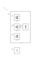
図1は、本発明に係わる運動推定装置の一実施形態の概略構成を示すブロック図である。同図において、本実施形態の運動推定装置1は、自動運転車両や移動ロボット等の自律移動機械に搭載され、自律移動機械の自己運動(移動や回転等)の状態を推定する装置である。 FIG. 1 is a block diagram showing a schematic configuration of an embodiment of a motion estimation apparatus according to the present invention. In the figure, a motion estimation device 1 according to the present embodiment is a device that is mounted on an autonomous mobile machine such as an autonomous driving vehicle or a mobile robot and estimates the state of self-motion (movement, rotation, etc.) of the autonomous mobile machine.
運動推定装置1は、自律移動機械の周辺環境を撮像するカメラ2と、CPU、ROMやRAM等のメモリ、入出力回路等により構成されたECU(Electronic Control Unit)3とを備えている。カメラ2の数としては、1つでも良いし、2つ以上あっても良い。
The motion estimation device 1 includes a
ECU3は、画像処理部4と、記憶部5と、運動推定部6と、駆動制御部7とを有している。画像処理部4は、カメラ2により取得された自律移動機械の周辺環境の撮像画像に対してフィルタ処理、2値化処理、特徴抽出処理等の画像処理を施し、画像フレームを生成する。
The ECU 3 includes an
記憶部5には、自動車等の車両、二輪車、自転車及び歩行者等といった自律移動機械とは独立して移動する移動物体の形状や姿勢等に関するデータ(移動物体データ)が予め記憶されている。移動物体データとしては、移動物体の種類毎に数多くのデータが登録されている。
The
運動推定部6は、画像処理部4で得られた画像フレームを入力し、記憶部5に記憶された移動物体データを用いて所定の処理を行い、自律移動機械がどのように動いているかを推定する。
The
駆動制御部7は、運動推定部6で推定された運動状態に応じて、自律移動機械の駆動系(自動運転車両の場合には操舵系も含む)を制御する。
The
図2は、運動推定部6により実行される運動推定処理の手順の詳細を示すフローチャートである。
FIG. 2 is a flowchart showing details of the procedure of the motion estimation process executed by the
同図において、まず最新の画像フレームT’及びその1つ前の画像フレームTを用意し、これらの画像フレームT,T’に存在する移動物体Oi,Oi’を検出し、移動物体Oi,Oi’に対応する画像領域Ri,Ri’を取得する(手順S101)。なお、i=1〜N(Nは検出された移動物体の数)である。 In the figure, first, the latest image frame T ′ and the previous image frame T are prepared, moving objects Oi, Oi ′ existing in these image frames T, T ′ are detected, and the moving objects Oi, Oi are detected. Image regions Ri and Ri 'corresponding to' are acquired (step S101). Note that i = 1 to N (N is the number of detected moving objects).
具体的には、画像フレームT,T’に存在する移動物体候補と記憶部5に記憶された移動物体データとを比較してパターン認識を行い、移動物体候補と何れかの移動物体データとの類似度が所定値以上のときに、当該移動物体候補を移動物体Oi,Oi’とする。
Specifically, the pattern recognition is performed by comparing the moving object candidate existing in the image frames T and T ′ with the moving object data stored in the
図3は、画像フレームT,T’の一例を示したものである。画像フレームT,T’には、移動物体(歩行者)O1,O1’に対応する画像領域R1,R1’と、移動物体(車両)O2,O2’ に対応する画像領域R2,R2’とが存在している。また、画像フレームT,T’には、3つの静止物体(建物等)も存在している。 FIG. 3 shows an example of the image frames T and T ′. The image frames T and T ′ include image areas R 1 and R 1 ′ corresponding to the moving objects (pedestrians) O 1 and O 1 ′, and image areas corresponding to the moving objects (vehicles) O 2 and O 2 ′. R 2 and R 2 ′ exist. There are also three stationary objects (buildings, etc.) in the image frames T and T ′.
続いて、既知の手法を用いて、カメラ2から見た場合の移動物体Oi,Oi’の位置Pi(Xi,Yi,Zi),Pi’(Xi’,Yi’,Zi’)を計算する(手順S102)。
Subsequently, the positions Pi (Xi, Yi, Zi) and Pi ′ (Xi ′, Yi ′, Zi ′) of the moving objects Oi, Oi ′ when viewed from the
そして、カメラ2から見た場合の各移動物体の位置座標から各移動物体の移動距離を求め、この移動距離と撮像画像の取得時間間隔(例えば100ms)とから各移動物体の速度Viを計算する(手順S103)。このとき、速度Viの算出精度を上げるためには、最新2枚の画像フレームT,T’だけでなく、過去何枚もの画像フレームの情報を用いて各移動物体の速度Viを求めるのが望ましい。
Then, the moving distance of each moving object is obtained from the position coordinates of each moving object when viewed from the
続いて、画像フレームT,T’において移動物体Oi,Oi’に対応する画像領域Ri,Ri’を除去する(手順S104)。例えば図3に示す画像フレームT,T’に対して本処理を実行すると、図4に示すように、移動物体O1,O1’に対応する画像領域R1,R1’と移動物体O2,O2’ に対応する画像領域R2,R2’とが取り除かれ、3つの静止物体が残った画像となる。 Subsequently, the image regions Ri and Ri ′ corresponding to the moving objects Oi and Oi ′ in the image frames T and T ′ are removed (step S104). For example, the image frame T shown in FIG. 3, 'by executing this processing for, as shown in FIG. 4, the moving object O 1, O 1' T image area corresponding to R 1, moves R 1 'object O The image regions R 2 and R 2 ′ corresponding to 2 and O 2 ′ are removed, resulting in an image in which three still objects remain.
続いて、移動物体Oi,Oi’に対応する画像領域Ri,Ri’が除去された後の画像領域の中から、画像フレームT,T’間の特徴点の対応点対Pj(j=1〜M:Mは対応点対の数)を取得する(手順S105)。特徴点は、画像フレームT,T’に残った静止物体における特徴的な部位を表す点のことである。 Subsequently, the corresponding point pair Pj (j = 1 to 1) of the feature points between the image frames T and T ′ from the image region after the image regions Ri and Ri ′ corresponding to the moving objects Oi and Oi ′ are removed. M: M is the number of corresponding point pairs) (step S105). The feature point is a point representing a characteristic part of the stationary object remaining in the image frames T and T ′.
続いて、特徴点の対応点対(特徴対応点)の数Mが予め決められた閾値よりも多いかどうかを判断する(手順S106)。特徴点の対応点対Pjの数Mが閾値よりも多いと判断されたときは、特徴点の対応点対Pjの位置関係に基づいて、画像フレームT,T’間における自律移動機械の運動推定を実施する(手順S107)。このとき、運動推定を行う手法としては、因子分解法(例えばC.Tomasi and Kanade,Shape and Motion from Image Streams under Orthography:aFactorization Method,International Journal of Computer Vision,pp.137-154,1992参照)等が用いられる。 Subsequently, it is determined whether or not the number M of corresponding point pairs (feature corresponding points) of feature points is greater than a predetermined threshold (step S106). When it is determined that the number M of corresponding point pairs Pj of feature points is larger than the threshold value, the motion estimation of the autonomous mobile machine between the image frames T and T ′ is performed based on the positional relationship of the corresponding point pairs Pj of feature points. (Step S107). At this time, as a method for performing motion estimation, a factorization method (see, for example, C. Tomasi and Kanade, Shape and Motion from Image Streams under Orthography: aFactorization Method, International Journal of Computer Vision, pp.137-154, 1992), etc. Is used.
一方、特徴点の対応点対Pjの数Mが閾値よりも多くないと判断されたときは、自律移動機械の過去の運動推定結果を用いて、画像フレームT,T’間における自律移動機械の運動推定を実施する(手順S108)。このとき、例えば自律移動機械の過去の動きを線形に外挿して、運動推定を行う。 On the other hand, when it is determined that the number M of corresponding point pairs Pj of feature points is not larger than the threshold, the autonomous mobile machine between the image frames T and T ′ is used by using the past motion estimation result of the autonomous mobile machine. Motion estimation is performed (step S108). At this time, for example, the motion estimation is performed by linearly extrapolating the past motion of the autonomous mobile machine.
なお、手順S108においては、自律移動機械の過去の運動推定結果に加えて、画像フレームT,T’に存在する特徴点の対応点対Pjの位置関係も用いて、自律移動機械の運動推定を実施しても良い。 In step S108, in addition to the past motion estimation result of the autonomous mobile machine, the motion estimation of the autonomous mobile machine is also performed using the positional relationship between the corresponding point pairs Pj of the feature points existing in the image frames T and T ′. You may carry out.
以上において、ECU3における記憶部5と運動推定部6の手順S101,S104とは、周辺環境の各撮像画像に存在する移動物体を検出し、移動物体に対応する画像領域を除去する画像領域除去手段を構成する。運動推定部6の手順S105は、移動物体に対応する画像領域を除去した後の各撮像画像から特徴対応点を抽出する特徴対応点抽出手段を構成する。運動推定部6の手順S107は、各撮像画像の特徴対応点の位置関係に基づいて、自律移動機械の運動状態を推定する第1推定手段を構成する。
In the above, the
また、運動推定部6の手順S106は、特徴対応点の数が所定値よりも多いかどうかを判断する判断手段を構成する。運動推定部6の手順S108は、判断手段により特徴対応点の数が所定値よりも多くないと判断されたときに、自律移動機械の過去の位置に基づいて、自律移動機械の運動状態を推定する第2推定手段を構成する。
Further, step S106 of the
図5は、本実施形態の運動推定装置1により自律移動機械の運動状態を推定する時の動作を模式的に示したものである。ここでは、図5(a)に示すように、走行中の自律移動機械の前方に既知物体A,Bが存在しているものとする。この場合には、既知物体A,Bがカメラ2により撮像されることで、既知物体A,Bが写っている画像フレームTが取得される。
FIG. 5 schematically shows an operation when the motion estimation apparatus 1 of the present embodiment estimates the motion state of the autonomous mobile machine. Here, as shown in FIG. 5A, it is assumed that the known objects A and B exist in front of the traveling autonomous mobile machine. In this case, the known objects A and B are imaged by the
既知物体A,Bが静止物体であり、その静止物体上の特徴点数が十分多い場合には、図5(b)に示すように、自律移動機械の走行によってカメラ2が静止物体に近づくようになる。このため、その時の静止物体をカメラ2で撮像して画像フレームT’を取得し、画像フレームT,T’間の特徴点の対応点対を求めることにより、自律移動機械の運動状態を正確に推定することができる。
When the known objects A and B are stationary objects and the number of feature points on the stationary objects is sufficiently large, as shown in FIG. 5B, the
ところで、既知物体A,Bが本当は移動物体であるのに静止物体であると仮定して、運動推定を行った場合には、図5(c)に示すように、実際には自律移動機械が前進しているにも拘わらず、自律移動機械が停止または後退していると誤推定されてしまう。 By the way, when the motion estimation is performed assuming that the known objects A and B are actually moving objects but are still objects, as shown in FIG. Although the vehicle is moving forward, it is erroneously estimated that the autonomous mobile machine is stopped or retracted.
これに対し本実施形態では、既知物体A,Bが移動物体である場合には、その事が認識可能であるため、移動後の移動物体をカメラ2で撮像して画像フレームT’を取得し、自律移動機械の過去の運動推定結果を用いることで、自律移動機械の運動状態を推定することができる。
On the other hand, in the present embodiment, when the known objects A and B are moving objects, this can be recognized. Therefore, the moving object after moving is imaged by the
以上のように本実施形態にあっては、連続する画像フレームT,T’に存在する移動物体Oi,Oi’を検出し、この移動物体Oi,Oi’に対応する画像領域Ri,Ri’を除去し、その後の画像フレームT,T’において特徴点の対応点対Pjを抽出し、対応点対Pjの数が閾値よりも多いときに、画像フレームT,T’間の特徴点の対応点対Pjの位置関係に基づいて自律移動機械の運動状態を推定する。このように画像フレームに移動物体が存在している場合には、その移動物体に対応する画像領域を画像フレームから除去するので、図5(c)に示すように移動物体を静止物体と仮定して運動推定を行うといったことが防止される。このとき、移動物体が停止している場合や、移動物体の速度変化がゼロに近い場合でも、移動物体に対応する画像領域を除去するので、移動物体の微妙な動きによる推定誤差を無くすことができる。これにより、自律移動機械の周囲に多数の移動物体が存在している場合でも、自律移動機械の運動推定を高精度に行うことができる。 As described above, in the present embodiment, the moving objects Oi and Oi ′ existing in the continuous image frames T and T ′ are detected, and the image areas Ri and Ri ′ corresponding to the moving objects Oi and Oi ′ are detected. The corresponding point pairs Pj of the feature points are extracted in the subsequent image frames T and T ′, and when the number of the corresponding point pairs Pj is larger than the threshold, the corresponding points of the feature points between the image frames T and T ′ The motion state of the autonomous mobile machine is estimated based on the positional relationship of the pair Pj. When a moving object is present in the image frame as described above, the image area corresponding to the moving object is removed from the image frame, so that the moving object is assumed to be a stationary object as shown in FIG. Thus, it is possible to prevent motion estimation. At this time, even if the moving object is stopped or the speed change of the moving object is close to zero, the image area corresponding to the moving object is removed, so that estimation errors due to subtle movements of the moving object can be eliminated. it can. Thereby, even when a large number of moving objects exist around the autonomous mobile machine, the motion of the autonomous mobile machine can be estimated with high accuracy.
また、特徴点の対応点対Pjの数が閾値よりも少ないときは、自律移動機械の過去の運動推定結果を運動推定に用いることで、画像フレームに存在する静止物体が少なくても、自律移動機械の運動状態を推定することができる。 In addition, when the number of feature point pairs Pj is less than the threshold value, the past movement estimation result of the autonomous mobile machine is used for motion estimation, so that even if there are few stationary objects in the image frame, autonomous movement The motion state of the machine can be estimated.
さらに、GPS(全地球測位システム)を利用して運動推定を行う場合には、GPS衛星からの電波が建物等で遮られて運動推定が困難になることがあり、また車輪の回転速度を検出して運動推定を行う場合には、路面でスリップすると運動推定が困難になることがあるが、本実施形態の運動推定装置1によれば、そのような不具合を回避することが可能となる。 Furthermore, when motion estimation is performed using GPS (Global Positioning System), radio waves from GPS satellites may be blocked by buildings, etc., making it difficult to estimate motion and detecting wheel rotation speed. When motion estimation is performed, it may be difficult to estimate motion when slipping on the road surface. However, according to the motion estimation device 1 of the present embodiment, it is possible to avoid such a problem.
図6は、運動推定部6により実行される運動推定処理の他の手順を示すフローチャートである。図中、図2に示すフローチャートと同一の手順には同じ符号を付し、その説明を省略する。
FIG. 6 is a flowchart showing another procedure of the motion estimation process executed by the
同図において、手順S106において特徴点の対応点対Pjの数Mが閾値よりも多くないと判断されたときは、自律移動機械の過去の運動推定結果を用いて、画像フレームT,T’間における自律移動機械の仮の運動推定を実施する(手順S111)。 In the figure, when it is determined in step S106 that the number M of corresponding point pairs Pj of feature points is not greater than the threshold value, the past motion estimation result of the autonomous mobile machine is used to determine the distance between the image frames T and T ′. The temporary motion estimation of the autonomous mobile machine in is performed (step S111).
続いて、上述した移動物体Oiの位置Pi及び移動物体の速度Viを用いて、画像フレームT’の時間におけるカメラ2から見た場合の移動物体Oi’の位置Pi’(Xi’,Yi’,Zi’)を補正する(手順S112)。このとき、移動物体が速度Viで等速度運動を行っていると仮定して、補正計算を行う。
Subsequently, using the position Pi of the moving object Oi and the speed Vi of the moving object, the position Pi ′ (Xi ′, Yi ′, Yi ′, moving object Oi ′ when viewed from the
そして、上記の移動物体Oiの位置Piと補正された移動物体Oi’の位置Pi’との位置関係と、移動物体の速度Viと、自律移動機械の仮の運動推定結果とに基づいて、画像フレームT,T’間における自律移動機械の運動推定を実施する(手順S113)。この時の運動推定法としては、例えば上記の手順S107と同様に因子分解法等を採用することができる。 Based on the positional relationship between the position Pi of the moving object Oi and the corrected position Pi ′ of the moving object Oi ′, the speed Vi of the moving object, and the provisional motion estimation result of the autonomous mobile machine, Motion estimation of the autonomous mobile machine between frames T and T ′ is performed (step S113). As the motion estimation method at this time, for example, a factorization method or the like can be employed as in the above-described procedure S107.
なお、手順S113においては、画像フレームT,T’に存在する特徴点の対応点対Pjの位置関係も用いて、自律移動機械の運動推定を実施しても良い。 In step S113, the motion of the autonomous mobile machine may be estimated using the positional relationship between the corresponding point pairs Pj of the feature points existing in the image frames T and T '.
以上において、運動推定部6の手順S102は、撮像器2に対する移動物体の位置を求める位置検出手段を構成する。運動推定部6の手順S103は、移動物体の速度を求める速度検出手段を構成する。運動推定部6の手順S111は、判断手段により特徴対応点の数が所定値よりも多くないと判断されたときに、自律移動機械の過去の位置に基づいて、自律移動機械の仮の運動状態を推定する仮推定手段を構成する。運動推定部6の手順S112,S113は、撮像器2に対する移動物体の位置と移動物体の速度と自律移動機械の仮の運動状態とに基づいて、自律移動機械の運動状態を推定する第2推定手段を構成する。
In the above, the procedure S102 of the
このような構成では、既知物体A,Bが移動物体である場合には、その事が認識可能であるため、図5(d)に示すように、移動後の移動物体をカメラ2で撮像して画像フレームT’を取得し、画像フレームT,T’間の移動物体の位置関係と移動物体の速度とを求め、移動物体の動きを予測することにより、自律移動機械の運動状態を正確に推定することができる。
In such a configuration, when the known objects A and B are moving objects, this is recognizable, so the moving object after moving is imaged by the
なお、本発明は、上記実施形態に限定されるものではない。例えば上記実施形態では、移動物体の速度Viを求め、静止物体上の特徴点の対応点対の数が閾値よりも少ないときは、移動物体が速度Viで等速度運動を行っていると仮定して運動推定を行うようにしたが、移動物体が等速度運動を行っていると仮定せずに、移動物体の加速度やジャーク等の速度変化を考慮して、運動推定を行っても良い。 The present invention is not limited to the above embodiment. For example, in the above embodiment, the speed Vi of the moving object is obtained, and when the number of corresponding point pairs of feature points on the stationary object is less than the threshold, it is assumed that the moving object is moving at a constant speed at the speed Vi. However, instead of assuming that the moving object is moving at a constant velocity, the movement may be estimated in consideration of the speed change of the moving object such as acceleration and jerk.
1…運動推定装置、2…カメラ(撮像器)、3…ECU、4…画像処理部、5…記憶部(画像領域除去手段)、6…運動推定部(画像領域除去手段、特徴対応点抽出手段、第1推定手段、判断手段、第2推定手段、位置検出手段、速度検出手段、仮推定手段)。 DESCRIPTION OF SYMBOLS 1 ... Motion estimation apparatus, 2 ... Camera (imaging device), 3 ... ECU, 4 ... Image processing part, 5 ... Memory | storage part (image area removal means), 6 ... Motion estimation part (Image area removal means, feature corresponding point extraction) Means, first estimation means, determination means, second estimation means, position detection means, speed detection means, provisional estimation means).
Claims (4)
前記周辺環境の各撮像画像に存在する移動物体を検出し、前記移動物体に対応する画像領域を除去する画像領域除去手段と、
前記移動物体に対応する画像領域を除去した後の前記各撮像画像から特徴対応点を抽出する特徴対応点抽出手段と、
前記各撮像画像の前記特徴対応点の位置関係に基づいて、前記自律移動機械の運動状態を推定する第1推定手段とを備えることを特徴とする運動推定装置。 In the motion estimation device that images the surrounding environment of the autonomous mobile machine with an imager and estimates the motion state of the autonomous mobile machine based on changes in each captured image of the surrounding environment,
An image area removing unit that detects a moving object present in each captured image of the surrounding environment and removes an image area corresponding to the moving object;
Feature-corresponding point extracting means for extracting feature-corresponding points from each of the captured images after removing the image region corresponding to the moving object;
A motion estimation apparatus comprising: first estimation means for estimating a motion state of the autonomous mobile machine based on a positional relationship between the feature corresponding points of the captured images.
前記第1推定手段は、前記判断手段により前記特徴対応点の数が前記所定値よりも多いと判断されたときに、前記各撮像画像の特徴対応点の位置関係に基づいて、前記自律移動機械の運動状態を推定することを特徴とする請求項1記載の運動推定装置。 A judgment means for judging whether or not the number of feature corresponding points is greater than a predetermined value;
The first estimating unit determines the autonomous mobile machine based on the positional relationship between the feature corresponding points of the captured images when the determining unit determines that the number of the feature corresponding points is larger than the predetermined value. The motion estimation apparatus according to claim 1, wherein the motion state of the motion is estimated.
前記移動物体の速度を求める速度検出手段と、
前記判断手段により前記特徴対応点の数が前記所定値よりも多くないと判断されたときに、前記自律移動機械の過去の位置に基づいて、前記自律移動機械の仮の運動状態を推定する仮推定手段と、
前記撮像器に対する前記移動物体の位置と前記移動物体の速度と前記自律移動機械の仮の運動状態とに基づいて、前記自律移動機械の運動状態を推定する第2推定手段とを更に備えることを特徴とする請求項2記載の運動推定装置。 Position detecting means for determining the position of the moving object with respect to the imager;
Speed detecting means for determining the speed of the moving object;
When the determination means determines that the number of feature corresponding points is not greater than the predetermined value, the temporary movement state of the autonomous mobile machine is estimated based on the past position of the autonomous mobile machine. An estimation means;
Second estimation means for estimating the movement state of the autonomous mobile machine based on the position of the moving object relative to the imager, the speed of the moving object, and the provisional movement state of the autonomous mobile machine. The motion estimation apparatus according to claim 2, wherein:
Priority Applications (2)
| Application Number | Priority Date | Filing Date | Title |
|---|---|---|---|
| JP2008163626A JP5107154B2 (en) | 2008-06-23 | 2008-06-23 | Motion estimation device |
| US12/488,878 US8213684B2 (en) | 2008-06-23 | 2009-06-22 | Motion estimating device |
Applications Claiming Priority (1)
| Application Number | Priority Date | Filing Date | Title |
|---|---|---|---|
| JP2008163626A JP5107154B2 (en) | 2008-06-23 | 2008-06-23 | Motion estimation device |
Publications (2)
| Publication Number | Publication Date |
|---|---|
| JP2010003253A true JP2010003253A (en) | 2010-01-07 |
| JP5107154B2 JP5107154B2 (en) | 2012-12-26 |
Family
ID=41584898
Family Applications (1)
| Application Number | Title | Priority Date | Filing Date |
|---|---|---|---|
| JP2008163626A Expired - Fee Related JP5107154B2 (en) | 2008-06-23 | 2008-06-23 | Motion estimation device |
Country Status (2)
| Country | Link |
|---|---|
| US (1) | US8213684B2 (en) |
| JP (1) | JP5107154B2 (en) |
Cited By (4)
| Publication number | Priority date | Publication date | Assignee | Title |
|---|---|---|---|---|
| JP2011204111A (en) * | 2010-03-26 | 2011-10-13 | Honda Motor Co Ltd | Vehicle periphery monitoring device |
| WO2018225480A1 (en) * | 2017-06-05 | 2018-12-13 | 日立オートモティブシステムズ株式会社 | Position estimating device |
| US10473456B2 (en) | 2017-01-25 | 2019-11-12 | Panasonic Intellectual Property Management Co., Ltd. | Driving control system and driving control method |
| US11388349B2 (en) | 2015-07-10 | 2022-07-12 | Panasonic Intellectual Property Management Co., Ltd. | Imaging device that generates multiple-exposure image data |
Families Citing this family (2)
| Publication number | Priority date | Publication date | Assignee | Title |
|---|---|---|---|---|
| JP5394296B2 (en) * | 2010-03-25 | 2014-01-22 | 富士フイルム株式会社 | Imaging apparatus and image processing method |
| KR20140056790A (en) * | 2012-10-31 | 2014-05-12 | 한국전자통신연구원 | Apparatus for image recognition and method thereof |
Citations (5)
| Publication number | Priority date | Publication date | Assignee | Title |
|---|---|---|---|---|
| JPH0944681A (en) * | 1995-08-01 | 1997-02-14 | Matsushita Electric Ind Co Ltd | Moving object area detector |
| JPH1151650A (en) * | 1997-08-04 | 1999-02-26 | Fuji Heavy Ind Ltd | Three-dimensional self-position recognizing device for mobile body |
| JP2005115420A (en) * | 2003-10-02 | 2005-04-28 | Kazuo Iwane | Three-dimensional shape generation device |
| JP2007278871A (en) * | 2006-04-07 | 2007-10-25 | Technical Research & Development Institute Ministry Of Defence | Apparatus for computing amount of movement |
| JP2008008797A (en) * | 2006-06-29 | 2008-01-17 | Toyota Motor Corp | Apparatus ande program for predicting camera's behavior |
Family Cites Families (13)
| Publication number | Priority date | Publication date | Assignee | Title |
|---|---|---|---|---|
| US5525883A (en) * | 1994-07-08 | 1996-06-11 | Sara Avitzour | Mobile robot location determination employing error-correcting distributed landmarks |
| JP4409035B2 (en) * | 2000-03-22 | 2010-02-03 | 本田技研工業株式会社 | Image processing apparatus, singular part detection method, and recording medium recording singular part detection program |
| US20030076417A1 (en) * | 2001-08-07 | 2003-04-24 | Patrick Thomas | Autonomous monitoring and tracking of vehicles in a parking lot to enforce payment rights |
| KR100493159B1 (en) * | 2002-10-01 | 2005-06-02 | 삼성전자주식회사 | Landmark, apparatus and method for determining position of autonomous vehicles effectively |
| KR100446636B1 (en) * | 2002-11-21 | 2004-09-04 | 삼성전자주식회사 | Apparatus and method for measuring ego motion of autonomous vehicles and 3D shape of object in front of autonomous vehicles |
| DE10323915A1 (en) * | 2003-05-23 | 2005-02-03 | Daimlerchrysler Ag | Camera-based position detection for a road vehicle |
| US20050234679A1 (en) * | 2004-02-13 | 2005-10-20 | Evolution Robotics, Inc. | Sequential selective integration of sensor data |
| US20070288141A1 (en) | 2004-06-22 | 2007-12-13 | Bergen James R | Method and apparatus for visual odometry |
| US20100222925A1 (en) * | 2004-12-03 | 2010-09-02 | Takashi Anezaki | Robot control apparatus |
| JP4564447B2 (en) * | 2004-12-14 | 2010-10-20 | 本田技研工業株式会社 | Autonomous mobile robot |
| US7634336B2 (en) * | 2005-12-08 | 2009-12-15 | Electronics And Telecommunications Research Institute | Localization system and method of mobile robot based on camera and landmarks |
| WO2007124502A2 (en) * | 2006-04-21 | 2007-11-01 | Sarnoff Corporation | Apparatus and method for object detection and tracking and roadway awareness using stereo cameras |
| US7840352B2 (en) * | 2006-09-05 | 2010-11-23 | Honeywell International Inc. | Method and system for autonomous vehicle navigation |
-
2008
- 2008-06-23 JP JP2008163626A patent/JP5107154B2/en not_active Expired - Fee Related
-
2009
- 2009-06-22 US US12/488,878 patent/US8213684B2/en active Active
Patent Citations (5)
| Publication number | Priority date | Publication date | Assignee | Title |
|---|---|---|---|---|
| JPH0944681A (en) * | 1995-08-01 | 1997-02-14 | Matsushita Electric Ind Co Ltd | Moving object area detector |
| JPH1151650A (en) * | 1997-08-04 | 1999-02-26 | Fuji Heavy Ind Ltd | Three-dimensional self-position recognizing device for mobile body |
| JP2005115420A (en) * | 2003-10-02 | 2005-04-28 | Kazuo Iwane | Three-dimensional shape generation device |
| JP2007278871A (en) * | 2006-04-07 | 2007-10-25 | Technical Research & Development Institute Ministry Of Defence | Apparatus for computing amount of movement |
| JP2008008797A (en) * | 2006-06-29 | 2008-01-17 | Toyota Motor Corp | Apparatus ande program for predicting camera's behavior |
Cited By (8)
| Publication number | Priority date | Publication date | Assignee | Title |
|---|---|---|---|---|
| JP2011204111A (en) * | 2010-03-26 | 2011-10-13 | Honda Motor Co Ltd | Vehicle periphery monitoring device |
| US11388349B2 (en) | 2015-07-10 | 2022-07-12 | Panasonic Intellectual Property Management Co., Ltd. | Imaging device that generates multiple-exposure image data |
| US11722784B2 (en) | 2015-07-10 | 2023-08-08 | Panasonic Intellectual Property Management Co., Ltd. | Imaging device that generates multiple-exposure image data |
| US10473456B2 (en) | 2017-01-25 | 2019-11-12 | Panasonic Intellectual Property Management Co., Ltd. | Driving control system and driving control method |
| US11333489B2 (en) | 2017-01-25 | 2022-05-17 | Panasonic Intellectual Property Management Co., Ltd. | Driving control system and driving control method |
| WO2018225480A1 (en) * | 2017-06-05 | 2018-12-13 | 日立オートモティブシステムズ株式会社 | Position estimating device |
| JP2018205142A (en) * | 2017-06-05 | 2018-12-27 | 日立オートモティブシステムズ株式会社 | Position estimation device |
| US11346670B2 (en) | 2017-06-05 | 2022-05-31 | Hitachi Astemo, Ltd. | Position estimating device |
Also Published As
| Publication number | Publication date |
|---|---|
| JP5107154B2 (en) | 2012-12-26 |
| US8213684B2 (en) | 2012-07-03 |
| US20100027847A1 (en) | 2010-02-04 |
Similar Documents
| Publication | Publication Date | Title |
|---|---|---|
| JP5587930B2 (en) | Distance calculation device and distance calculation method | |
| JP4899424B2 (en) | Object detection device | |
| JP2016081525A (en) | Vehicular image recognition system and corresponding method | |
| JP6138861B2 (en) | Distance calculation device | |
| JP6499047B2 (en) | Measuring device, method and program | |
| WO2013132951A1 (en) | Distance calculation device and distance calculation method | |
| JP5107154B2 (en) | Motion estimation device | |
| JP2006338272A (en) | Vehicle behavior detector and vehicle behavior detection method | |
| KR20180021159A (en) | Signaling device and signaling device recognition method | |
| US20170161912A1 (en) | Egomotion estimation system and method | |
| WO2014002692A1 (en) | Stereo camera | |
| US8160300B2 (en) | Pedestrian detecting apparatus | |
| WO2016151976A1 (en) | Moving body detection device, image processing device, moving body detection method, and integrated circuit | |
| WO2016151977A1 (en) | Moving body detection device, image processing device, moving body detection method, and integrated circuit | |
| JP2018073275A (en) | Image recognition device | |
| JP2014238409A (en) | Distance calculation device and distance calculation method | |
| JP4069919B2 (en) | Collision determination device and method | |
| JP2008003696A (en) | Image processing apparatus and image processing method | |
| JP2008160635A (en) | Camera state detection method | |
| JP6886136B2 (en) | Alignment device, alignment method and computer program for alignment | |
| JP2006010652A (en) | Object-detecting device | |
| JP4062306B2 (en) | Image processing apparatus and method | |
| JP4244887B2 (en) | Moving position prediction apparatus, moving position prediction method, collision determination apparatus, and collision determination method | |
| JP2003271968A (en) | Device and method for detecting mobile-body | |
| JP2020076714A (en) | Position attitude estimation device |
Legal Events
| Date | Code | Title | Description |
|---|---|---|---|
| A621 | Written request for application examination |
Free format text: JAPANESE INTERMEDIATE CODE: A621 Effective date: 20110518 |
|
| A977 | Report on retrieval |
Free format text: JAPANESE INTERMEDIATE CODE: A971007 Effective date: 20120301 |
|
| A131 | Notification of reasons for refusal |
Free format text: JAPANESE INTERMEDIATE CODE: A131 Effective date: 20120313 |
|
| A521 | Request for written amendment filed |
Free format text: JAPANESE INTERMEDIATE CODE: A523 Effective date: 20120612 |
|
| TRDD | Decision of grant or rejection written | ||
| A01 | Written decision to grant a patent or to grant a registration (utility model) |
Free format text: JAPANESE INTERMEDIATE CODE: A01 Effective date: 20120911 |
|
| A01 | Written decision to grant a patent or to grant a registration (utility model) |
Free format text: JAPANESE INTERMEDIATE CODE: A01 |
|
| A61 | First payment of annual fees (during grant procedure) |
Free format text: JAPANESE INTERMEDIATE CODE: A61 Effective date: 20121003 |
|
| R150 | Certificate of patent or registration of utility model |
Ref document number: 5107154 Country of ref document: JP Free format text: JAPANESE INTERMEDIATE CODE: R150 Free format text: JAPANESE INTERMEDIATE CODE: R150 |
|
| FPAY | Renewal fee payment (event date is renewal date of database) |
Free format text: PAYMENT UNTIL: 20151012 Year of fee payment: 3 |
|
| R250 | Receipt of annual fees |
Free format text: JAPANESE INTERMEDIATE CODE: R250 |
|
| R250 | Receipt of annual fees |
Free format text: JAPANESE INTERMEDIATE CODE: R250 |
|
| R250 | Receipt of annual fees |
Free format text: JAPANESE INTERMEDIATE CODE: R250 |
|
| R250 | Receipt of annual fees |
Free format text: JAPANESE INTERMEDIATE CODE: R250 |
|
| R250 | Receipt of annual fees |
Free format text: JAPANESE INTERMEDIATE CODE: R250 |
|
| R250 | Receipt of annual fees |
Free format text: JAPANESE INTERMEDIATE CODE: R250 |
|
| R250 | Receipt of annual fees |
Free format text: JAPANESE INTERMEDIATE CODE: R250 |
|
| LAPS | Cancellation because of no payment of annual fees |