JP2009532125A - Deformable flap catch mechanism for occluder equipment - Google Patents
Deformable flap catch mechanism for occluder equipment Download PDFInfo
- Publication number
- JP2009532125A JP2009532125A JP2009503288A JP2009503288A JP2009532125A JP 2009532125 A JP2009532125 A JP 2009532125A JP 2009503288 A JP2009503288 A JP 2009503288A JP 2009503288 A JP2009503288 A JP 2009503288A JP 2009532125 A JP2009532125 A JP 2009532125A
- Authority
- JP
- Japan
- Prior art keywords
- flap
- medical device
- occluder
- catch
- catch member
- Prior art date
- Legal status (The legal status is an assumption and is not a legal conclusion. Google has not performed a legal analysis and makes no representation as to the accuracy of the status listed.)
- Pending
Links
Images


Classifications
-
- A—HUMAN NECESSITIES
- A61—MEDICAL OR VETERINARY SCIENCE; HYGIENE
- A61B—DIAGNOSIS; SURGERY; IDENTIFICATION
- A61B17/00—Surgical instruments, devices or methods, e.g. tourniquets
- A61B17/0057—Implements for plugging an opening in the wall of a hollow or tubular organ, e.g. for sealing a vessel puncture or closing a cardiac septal defect
- A61B2017/00575—Implements for plugging an opening in the wall of a hollow or tubular organ, e.g. for sealing a vessel puncture or closing a cardiac septal defect for closure at remote site, e.g. closing atrial septum defects
- A61B2017/00592—Elastic or resilient implements
-
- A—HUMAN NECESSITIES
- A61—MEDICAL OR VETERINARY SCIENCE; HYGIENE
- A61B—DIAGNOSIS; SURGERY; IDENTIFICATION
- A61B17/00—Surgical instruments, devices or methods, e.g. tourniquets
- A61B17/0057—Implements for plugging an opening in the wall of a hollow or tubular organ, e.g. for sealing a vessel puncture or closing a cardiac septal defect
- A61B2017/00575—Implements for plugging an opening in the wall of a hollow or tubular organ, e.g. for sealing a vessel puncture or closing a cardiac septal defect for closure at remote site, e.g. closing atrial septum defects
- A61B2017/00606—Implements H-shaped in cross-section, i.e. with occluders on both sides of the opening
-
- A—HUMAN NECESSITIES
- A61—MEDICAL OR VETERINARY SCIENCE; HYGIENE
- A61B—DIAGNOSIS; SURGERY; IDENTIFICATION
- A61B17/00—Surgical instruments, devices or methods, e.g. tourniquets
- A61B17/0057—Implements for plugging an opening in the wall of a hollow or tubular organ, e.g. for sealing a vessel puncture or closing a cardiac septal defect
- A61B2017/00575—Implements for plugging an opening in the wall of a hollow or tubular organ, e.g. for sealing a vessel puncture or closing a cardiac septal defect for closure at remote site, e.g. closing atrial septum defects
- A61B2017/00619—Locking means for locking the implement in expanded state
-
- A—HUMAN NECESSITIES
- A61—MEDICAL OR VETERINARY SCIENCE; HYGIENE
- A61B—DIAGNOSIS; SURGERY; IDENTIFICATION
- A61B17/00—Surgical instruments, devices or methods, e.g. tourniquets
- A61B17/0057—Implements for plugging an opening in the wall of a hollow or tubular organ, e.g. for sealing a vessel puncture or closing a cardiac septal defect
- A61B2017/00575—Implements for plugging an opening in the wall of a hollow or tubular organ, e.g. for sealing a vessel puncture or closing a cardiac septal defect for closure at remote site, e.g. closing atrial septum defects
- A61B2017/00623—Introducing or retrieving devices therefor
-
- A—HUMAN NECESSITIES
- A61—MEDICAL OR VETERINARY SCIENCE; HYGIENE
- A61B—DIAGNOSIS; SURGERY; IDENTIFICATION
- A61B17/00—Surgical instruments, devices or methods, e.g. tourniquets
- A61B2017/00831—Material properties
- A61B2017/00862—Material properties elastic or resilient
Landscapes
- Health & Medical Sciences (AREA)
- Surgery (AREA)
- Life Sciences & Earth Sciences (AREA)
- Biomedical Technology (AREA)
- Nuclear Medicine, Radiotherapy & Molecular Imaging (AREA)
- Engineering & Computer Science (AREA)
- Cardiology (AREA)
- Heart & Thoracic Surgery (AREA)
- Medical Informatics (AREA)
- Molecular Biology (AREA)
- Animal Behavior & Ethology (AREA)
- General Health & Medical Sciences (AREA)
- Public Health (AREA)
- Veterinary Medicine (AREA)
- Surgical Instruments (AREA)
Abstract
心房中隔欠損、卵円孔開存(PFO)及び他の中隔及び脈管欠損のような物理的異常の閉鎖のための閉塞装置用の装置、送達システム及び送達技術。より詳細には、送達シース内で、オクルーダを展開し、輪郭が拡張した構成に保持するキャッチ部材を含むオクルーダ。キャッチ部材の近位端部は、オクルーダの近位端部に位置した場合に、オクルーダを輪郭が拡張した構成に保持するフラップを含む。フラップは、軸方向及び半径方向に前後に曲げることによりフラップが変形することができるサイズに、このように変形することができる材料から形成される。ある実施形態の場合には、フラップは、ノッチにより分割されるセグメントを含む。ある実施形態の場合には、近位方向にフラップを変形させるには、遠位方向にフラップを変形させる力とは異なる大きさの力を必要とする。
【選択図】図9Devices, delivery systems and techniques for occlusive devices for closure of physical abnormalities such as atrial septal defects, patent foramen ovale (PFO) and other septal and vascular defects. More particularly, an occluder that includes a catch member that deploys the occluder within the delivery sheath and holds it in an expanded profile configuration. The proximal end of the catch member includes a flap that, when located at the proximal end of the occluder, holds the occluder in an expanded profile configuration. The flap is formed from a material that can be deformed in this way to a size that allows the flap to deform by bending back and forth in the axial and radial directions. In some embodiments, the flap includes a segment divided by a notch. In some embodiments, deforming the flap in the proximal direction requires a different magnitude of force than the force deforming the flap in the distal direction.
[Selection] Figure 9
Description
(関連出願への相互参照)
[0001] 本出願は、米国特許法第119条第(e)項により、2006年3月31日出願の米国仮特許出願第60/787,988号の利益を主張する。その内容は参照により全体を本明細書に組み込むものとする。
(Cross-reference to related applications)
[0001] This application claims the benefit of US Provisional Patent Application No. 60 / 787,988, filed March 31, 2006, in accordance with Section 119 (e) of the US Patent Act. The contents of which are incorporated herein by reference in their entirety.
[0002] 本発明は、概して、心房中隔欠損、卵円孔開存及び他の中隔及び脈管欠損のような物理的異常を閉鎖するための閉塞装置に関し、特に、オクルーダを展開した状態に維持するためのキャッチ機構に関する。本発明は、また、このような装置に対する送達システム及び機構に関する。 [0002] The present invention relates generally to occlusion devices for closing physical abnormalities such as atrial septal defects, patent foramen ovale and other septal and vascular defects, and in particular, with the occluder deployed. It is related with the catch mechanism for maintaining. The invention also relates to delivery systems and mechanisms for such devices.
[0003] 図1の卵円孔開存(PFO)は、心臓10の右心房11と左心房13との間の壁部内の永続的な一方向の通常はフラップの形をしている開口部である。左心房(LA)の圧力は、通常、右心房(RA)の圧力よりも高いので、フラップは通常閉じたままである。しかし、ある状況の下では、右心房の圧力が、左心房の圧力よりも高くなる場合があり、血液が右心房11から左心房13に移動し、血餅が体循環に入り込む恐れがある。このような状況は除去することが望ましい。
[0003] The patent foramen ovale (PFO) of FIG. 1 is a permanent unidirectional normally flap-shaped opening in the wall between the
[0004] 卵円孔開存は、胎児の妊娠時に所望の目的を果たすためのものである。血液は、発育中の肺を通してではなく、臍帯を通して酸素の供給を受けるので、血液は、胎児の心臓の循環システムにより、左右を短絡するための生理的導管としての卵円孔開存を通して流れることができる。誕生後は、肺循環が確立するので、左心房の血流及び圧力が増大するために、卵円孔開存の機能的な閉鎖が起こる。この機能的な閉鎖の後では、組織の2つの重なっている層、すなわち、1次中隔14と2次中隔16の解剖学的閉鎖が起こる。しかし、PFOは、多くの成人に依然として存在することが分かっている。
[0004] Patent foramen ovale is intended to serve a desired purpose during fetal pregnancy. Since blood is supplied with oxygen through the umbilical cord rather than through the developing lung, blood flows through the patent foramen ovale as a physiological conduit for short circuiting from side to side by the fetal heart circulation system. Can do. After birth, the functional circulation of the patent foramen ovale occurs due to increased blood flow and pressure in the left atrium as the pulmonary circulation is established. After this functional closure, an anatomical closure of two overlapping layers of tissue, the
[0005] PFOの存在は、通常、他の点で健康な成人の場合、治療的重要性を持たないと見なされている。PFOを介しての奇異性塞栓症は、PFOを有していて、卒中又は一過性虚血発作(TIA)を起こしたことがあるが、虚血発作の他の原因が分かっていない患者に対する診断の際に考慮の対象になる。現在のところ、原因と結果との関連についての確証はないが、多くの研究から、PFOの存在と奇異性塞栓症又は卒中に対するリスクとの間に強い関連性があることが確認されている。さらに、脳血管症を起こしたPFOを有している患者は、将来脳血管症を起こすリスクが増大する有意な証拠がある。もう1つの状態、慢性偏頭痛も、PFOの存在と関連があることが分かっている。解明するための研究が依然として行われているが、PFOを閉鎖すると、多くの患者の偏頭痛が消滅するか、又はかなり軽減することも分かっている。 [0005] The presence of PFO is usually considered to be of no therapeutic importance in otherwise healthy adults. Oddly heterogeneous embolism via PFO is for patients with PFO who have had a stroke or transient ischemic attack (TIA) but other causes of ischemic attack are not known It will be considered in the diagnosis. At present, there is no evidence of an association between cause and effect, but many studies have confirmed that there is a strong association between the presence of PFO and the risk for paradoxical embolism or stroke. Furthermore, there is significant evidence that patients with PFOs with cerebrovascular disease have an increased risk of developing cerebrovascular disease in the future. Another condition, chronic migraine, has also been found to be associated with the presence of PFO. Although research is still underway, it has also been found that migrating migraines in many patients disappears or is significantly reduced when the PFO is closed.
[0006] 抗血液凝固が禁忌となっている場合のようないくつかの場合には、PFOを閉鎖するのに外科手術が必要な場合もあるし、又は望ましい場合もある。外科手術は、通常、2次中隔を1次中隔に取り付けることにより、閉鎖したPFOを縫合するステップを含む。この縫合による取り付けは、断続的又は連続的縫合により行うこともできるし、又は通常外科医は、直接目で見ながらPFOを分路する一般的な方法である。 [0006] In some cases, such as when anticoagulation is contraindicated, surgery may be necessary or desirable to close the PFO. Surgery typically involves suturing a closed PFO by attaching a secondary septum to the primary septum. This suturing attachment can be done by intermittent or continuous suturing, or is usually a common method for a surgeon to shunt the PFO while looking directly at the eye.
[0007] 最初は、心房中隔欠損(ASD)の経皮的閉鎖のために開発された傘状の装置及び種々の他の類似の機械的閉鎖装置が、PFOを閉鎖するために種々の場合に使用されてきた。これらの装置を使用すれば、潜在的に、患者は、抗血液凝固療法に多くの場合関連して起こる副作用を回避することができ、また体を傷をつける外科手術のリスクを回避することができる。しかし、ADSのために設計された傘状の装置等は、PFO閉鎖装置として使用するための最適な装置ではない。 [0007] Initially, an umbrella-like device developed for percutaneous closure of an atrial septal defect (ASD) and various other similar mechanical closure devices have been used in various cases to close a PFO. Has been used. With these devices, patients can potentially avoid the side effects often associated with anticoagulant therapy, and avoid the risk of surgery hurting the body. it can. However, umbrella-like devices designed for ADS are not optimal devices for use as PFO closure devices.
[0008] 現在入手可能な中隔閉鎖装置は、技術的に複雑な植え込み処置を含むいくつかの欠点を有する。さらに、血栓、構成要素の破断、誘導システムの故障、心臓組織の穿孔、及び残留漏洩によりかなり重大な合併症を起こす。多くの装置は、高い中隔の輪郭を有し、大きな質量の異物を含み、これにより装置の望ましくない身体の適応を起こす場合がある。ASD装置が孔を閉鎖するように設計されているとしても、多くの装置は、PFOのフラップ状の解剖学的構造に対する解剖学的適合性に欠けている。それ故、PFOを閉鎖するためにASD装置を挿入した場合、狭い開口部及び薄いフラップが、正しい展開の障害になる場合がある。閉鎖性のシールが形成された場合でも、装置はある角度で心臓内で拡がる場合があり、いくつかの構成要素が中隔に対してしっかりと固定されないで、血行力学的障害により血栓ができる恐れがある。最後に、いくつかの中隔閉鎖装置は製造するのが難しく、そのため製品の性能にバラツキが起こる。 [0008] Currently available septal closure devices have several disadvantages, including technically complex implantation procedures. In addition, thrombosis, component rupture, guidance system failure, heart tissue perforation, and residual leakage cause significant complications. Many devices have a high septal profile and contain large masses of foreign material, which can cause undesirable body adaptations of the device. Even if the ASD device is designed to close the hole, many devices lack anatomical compatibility with the PFO flap anatomy. Therefore, when an ASD device is inserted to close the PFO, narrow openings and thin flaps can interfere with proper deployment. Even when an occlusive seal is formed, the device may expand in the heart at an angle, and some components may not be firmly fixed to the septum, which can cause a thrombus due to hemodynamic disturbances There is. Finally, some septal closure devices are difficult to manufacture, resulting in variations in product performance.
[0009] 身体管腔を通してオクルーダ及び他の医療装置を送達するために、種々の装置及び送達システムが開発されてきた。従来技術のいくつかの送達システムは、送達システムから除去した場合、送達した構成に容易に拡がる装置を供給するために使用された。他のオクルーダは、展開した構成に容易に拡がらず、種々の技術が装置の構成を展開した構成に変化させるために使用された。後者の場合、オクルーダが所望の送達位置に送達され、展開した場合、オクルーダは、装置を展開した構成に維持するキャッチシステムを含んでいなければならない。 [0009] Various devices and delivery systems have been developed to deliver occluders and other medical devices through body lumens. Several prior art delivery systems have been used to provide a device that, when removed from the delivery system, easily expands into the delivered configuration. Other occluders were not easily extended to the deployed configuration, and various techniques were used to change the configuration of the device to the deployed configuration. In the latter case, when the occluder is delivered to the desired delivery location and deployed, the occluder must include a catch system that maintains the device in the deployed configuration.
[0010] 本明細書に開示する装置及び技術は、このような装置を送達し、回収するための従来技術の中隔閉鎖装置及び技術のこれら及び他の問題を解決するように設計されている。 [0010] The devices and techniques disclosed herein are designed to solve these and other problems of prior art septal closure devices and techniques for delivering and retrieving such devices. .
[0011] 本発明の態様は、身体の所望の位置にインプラントを送達し、装置を展開した構成に固定するためのオクルーダ装置及び技術を含む。これらの送達技術は、特に、ポリマー管又は実質的に筒状体からできている中隔オクルーダに関連するが、関連するものはこのような中隔オクルーダに限定されない。これらの送達技術は、中隔オクルーダと一緒に使用することができるばかりでなく、基礎となる管状構造からできている他の拡張可能な装置のような他の医療装置にも適用することができる。一態様においては、本発明は、所望の送達位置において、装置を展開した構成に保持するキャッチシステムを提供する。ある実施形態の場合には、キャッチシステムは、送達中、オクルーダの近位端部の管腔内に適合するように構成されているフラップを含むキャッチ部材を備える。フラップはオクルーダの端部の近くに位置していて、キャッチシステムは、装置を展開した構成に保持する。ある実施形態の場合には、キャッチシステムは、装置を展開した場合に、装置の短くなった軸方向の長さをそのまま維持する。 [0011] Aspects of the invention include occluder devices and techniques for delivering an implant to a desired location on the body and securing the device in a deployed configuration. These delivery techniques are particularly relevant to septal occluders made from polymer tubes or substantially cylindrical bodies, but are not limited to such septal occluders. These delivery techniques can be used with septal occluders as well as other medical devices such as other expandable devices made from the underlying tubular structure. . In one aspect, the present invention provides a catch system that holds the device in a deployed configuration at a desired delivery location. In certain embodiments, the catch system comprises a catch member that includes a flap that is configured to fit within the lumen of the proximal end of the occluder during delivery. The flap is located near the end of the occluder and the catch system holds the device in the deployed configuration. In some embodiments, the catch system maintains the shortened axial length of the device as it is deployed.
[0012] ある実施形態の場合には、フラップは、丸みが付いた断面を有することができ、フラップは、キャッチ部材の近位端部から半径方向に延びる2つ以上のウィングを備えることができる。フラップは、約1から約2の最小の厚さ/幅比を有することができる。フラップを含むキャッチ部材の実施形態は、装置をねじシステム及びコレット式の固定システムを含む送達システムに取り付けるために、任意の数の固定システムと一緒に有利に使用することができる。 [0012] In certain embodiments, the flap can have a rounded cross-section, and the flap can comprise two or more wings extending radially from the proximal end of the catch member. . The flap may have a minimum thickness / width ratio of about 1 to about 2. Catch member embodiments that include a flap can be advantageously used with any number of fixation systems to attach the device to a delivery system that includes a screw system and a collet-type fixation system.
[0013] 一態様においては、本発明は、身体内で開口部を閉鎖するための折り畳み可能な医療装置を提供する。この医療装置は、輪郭が縮小した第1の構成及び輪郭が拡張した第2の構成を有し、所望の送達位置内の送達システムを通して送達することができる第2の構成を有する。この装置は、近位側と遠位側を有し、その場合、閉塞部分は第1の構成から第2の構成に変化することができ、さらに医療装置を第2の構成に保持するためのキャッチシステムを含む。キャッチシステムは、曲げることができるその近位端部のところに、フラップを含むキャッチ部材を含み、フラップは医療装置を第2の構成に保持する。 [0013] In one aspect, the present invention provides a foldable medical device for closing an opening within a body. The medical device has a first configuration with a reduced profile and a second configuration with an expanded profile, and a second configuration that can be delivered through a delivery system in a desired delivery location. The device has a proximal side and a distal side, in which case the occlusion portion can change from the first configuration to the second configuration and further for holding the medical device in the second configuration Includes catch system. The catch system includes a catch member that includes a flap at its proximal end that can be bent, the flap holding the medical device in a second configuration.
[0014] ある実施形態の場合には、フラップは、2つのウィングを含む。ある実施形態の場合には、ウィングは、切断V字形ノッチにより分離している。ある実施形態の場合には、フラップは、半径方向の一番遠い縁部に丸みが付いた面を有する。ある実施形態の場合には、フラップは半径方向の最も外側の表面に丸みが付いた面を有する。ある実施形態の場合には、フラップは楕円形の形状を有する。ある実施形態の場合には、フラップは、厚さの幅に対する比が約1から約2である。ある実施形態の場合には、フラップは、半径方向の一番遠い縁部に丸みが付いた面を有する2つのウィングを含む。ある実施形態の場合には、フラップは、キャッチ部材の最近位端部のところに配置される。 [0014] In certain embodiments, the flap includes two wings. In some embodiments, the wings are separated by a cut V-shaped notch. In some embodiments, the flap has a rounded surface at the radially farthest edge. In some embodiments, the flap has a rounded surface on the radially outermost surface. In some embodiments, the flap has an oval shape. In some embodiments, the flap has a thickness to width ratio of about 1 to about 2. In some embodiments, the flap includes two wings having a rounded surface at the radially farthest edge. In some embodiments, the flap is located at the proximal end of the catch member.
[0015] ある実施形態の場合には、回収するためにフラップを変形させるのに必要な第1の力は、展開のためにフラップを変形するのに必要な第2の力より大きい。 [0015] In certain embodiments, the first force required to deform the flap for retrieval is greater than the second force required to deform the flap for deployment.
[0016] ある実施形態の場合には、フラップは、送達及び回収中、オクルーダの内部通路内に嵌合し、送達中、オクルーダの内部通路と第1の干渉を有し、回収中、オクルーダの内部通路と第2の干渉を有し、第2の干渉は、第1の干渉より大きい。 [0016] In certain embodiments, the flap fits within the occluder internal passage during delivery and retrieval and has a first interference with the occluder internal passage during delivery and during retrieval the occluder There is a second interference with the internal passage, the second interference being greater than the first interference.
[0017] ある実施形態の場合には、キャッチ部材は、フラップから遠位に第1の外径を有し、フラップから近位に第2の外径を有し、第2の外径は第1の外径より大きい。 [0017] In certain embodiments, the catch member has a first outer diameter distal from the flap, a second outer diameter proximal from the flap, and the second outer diameter is the first outer diameter. Greater than 1 outer diameter.
[0018] ある実施形態の場合には、近位側のフラップの基部は湾曲していて、遠位側のフラップの基部よりも大きな半径を有する。 [0018] In certain embodiments, the proximal flap base is curved and has a larger radius than the distal flap base.
[0019] 他の態様においては、本発明は、輪郭が縮小した第1の構成及び輪郭が拡張した第2の構成を有する、身体内で開口部を閉鎖するための折り畳み可能な医療装置を提供する。この医療装置は、送達システムを通して所望の送達位置内に送達することができる。この医療装置は、オクルーダの全長に沿った軸方向通路を含み、輪郭が縮小した構成から輪郭が拡張した構成に変化することができる閉塞部分を含む。医療装置は、また、通路内にキャッチ部材を含んでいる状態で、オクルーダが、輪郭が縮小した構成から輪郭が拡張した構成に変化することができるように、通路内に配置することができるキャッチ部材を含む。キャッチ部材は、閉塞部分の近位端部に対して軸方向に移動することができるキャッチ部材の近位端部上にフラップを含む。オクルーダが輪郭が拡張した構成をしている場合には、フラップが輪郭が拡張した構成でオクルーダを固定するように、フラップは軸方向通路の近くに配置される。 [0019] In another aspect, the present invention provides a foldable medical device for closing an opening in a body having a first configuration with a reduced profile and a second configuration with an expanded profile. To do. The medical device can be delivered through a delivery system and into a desired delivery location. The medical device includes an axial passage along the entire length of the occluder and includes an occlusion that can change from a reduced profile configuration to an expanded profile configuration. The medical device also includes a catch member in the passage and can be placed in the passage so that the occluder can change from a reduced profile configuration to an expanded profile configuration. Includes members. The catch member includes a flap on the proximal end of the catch member that can move axially relative to the proximal end of the occlusion portion. If the occluder is configured with an expanded profile, the flap is positioned near the axial passage so that the flap secures the occluder in an expanded profile configuration.
[0020] 少なくともある実施形態の場合には、装置は管から形成される。ある実施形態の場合には、管は、金属、形状記憶材料、合金、ポリマー、生物吸収可能なポリマー、及びこれらの組合せからなるグループから選択した材料を含む。特定の実施形態の場合には、管は形状記憶ポリマーを含む。特定の実施形態の場合には、管はニチノールを含む。ある実施形態の場合には、管は材料の平坦な部片を管状に巻くことにより形成される。ある実施形態の場合には、装置は管を切断することにより形成される。他の実施形態の場合には、装置は管状に配置されている複数のフィラメントから形成される。装置は装置の軸方向の長さを短縮することにより、その展開した構成で設置される。 [0020] In at least some embodiments, the device is formed from a tube. In certain embodiments, the tube comprises a material selected from the group consisting of metals, shape memory materials, alloys, polymers, bioabsorbable polymers, and combinations thereof. In certain embodiments, the tube comprises a shape memory polymer. In certain embodiments, the tube comprises nitinol. In some embodiments, the tube is formed by rolling a flat piece of material into a tube. In some embodiments, the device is formed by cutting a tube. In other embodiments, the device is formed from a plurality of filaments arranged in a tube. The device is installed in its deployed configuration by reducing the axial length of the device.
[0021] 本発明の他の態様及び実施形態については、以下に図示し、説明する。 [0021] Other aspects and embodiments of the invention are illustrated and described below.
[0043] 本発明の種々の態様は、身体の組織内の開口部を閉鎖するためのこのような装置を送達するための装置、送達/回収システム、及び技術を含む。より詳細には、以下に詳細に説明するように、上記オクルーダは、心臓の心房中隔内のASD、VSD(心室中隔欠損)又はPFOを閉鎖するために使用することができる。ASD、VSD又はPFOを参照しながらいくつかの実施形態について説明するが、当業者であれば、本発明の装置及び方法は、他の解剖学的症状を治療するためにも使用することができることを理解することができるだろう。それ故、本発明を、任意の特定の解剖学的症状にしか適用することができないと見なすべきではない。さらに、本発明の態様である、送達し、回収するための、また装置を展開状態に保持するためのシステム及び方法は、また、オクルーダ以外の他のタイプの装置、特に管状の輪郭を有する装置と一緒に使用することができる。 [0043] Various aspects of the invention include devices, delivery / recovery systems, and techniques for delivering such devices for closing openings in body tissue. More particularly, as described in detail below, the occluder can be used to close an ASD, VSD (ventricular septal defect) or PFO in the atrial septum of the heart. Although some embodiments will be described with reference to ASD, VSD or PFO, those skilled in the art will recognize that the device and method of the present invention can also be used to treat other anatomical conditions. Would be able to understand. Therefore, the present invention should not be considered as applicable only to any particular anatomical condition. Furthermore, systems and methods for delivery and retrieval and for holding the device in an expanded state, which are aspects of the present invention, also include other types of devices other than occluders, particularly devices having a tubular profile. Can be used together with.
[0044] 本明細書においては、「遠位」という用語は、カテーテル挿入位置から離間する方向を意味し、「近位」という用語は、挿入位置に近い方向を意味する。さらに、「送達構成」という用語は、送達カテーテル内で輪郭が縮小した場合のオクルーダのような装置の構成を意味する。「展開した構成」という用語は、所望の植え込み位置のようなカテーテルから展開した場合のオクルーダのような装置の構成を意味する。上記実施形態の構成要素を識別するために使用する参照符号は、構成要素が図示されている複数のすべての図面上で使用している。参照符号は、本発明及び異なる図面に示す構成要素間の関連の全体的な理解を助けるためのものである。 [0044] As used herein, the term "distal" refers to the direction away from the catheter insertion position, and the term "proximal" refers to the direction close to the insertion position. Furthermore, the term “delivery configuration” means the configuration of a device such as an occluder when the profile is reduced within the delivery catheter. The term “deployed configuration” refers to the configuration of a device such as an occluder when deployed from a catheter, such as the desired implantation location. The reference numerals used to identify the components of the above embodiment are used on all the drawings in which the components are illustrated. Reference numerals are provided to aid in an overall understanding of the present invention and the relationships between components shown in different figures.
[0045] 本明細書においては、「弾性」という用語は、変形のための力が加わった場合に弾性により材料を変形させ(例えば、形状を変えるというように)、次に、変形のための力が取り除かれた場合に、変形前の形状に戻る材料の特性を意味する。 [0045] As used herein, the term "elasticity" refers to a material that is elastically deformed (eg, changes shape) when a deformation force is applied, and then for deformation. It refers to the property of a material that returns to its original shape when the force is removed.
[0046] 図1は、右心房11及び左心房13を有し、種々の解剖学的開口部18a及び18bを含んでいる人間の心臓である。心房中隔12は、1次中隔14及び2次中隔16を含む。中隔12の解剖学的形状は、人により種々様々である。ある人々の場合には、1次中隔14は、2次中隔16まで延びていて、その上に重なっている。1次中隔14は非常に薄い場合がある。解剖学的開口部18aが存在する場合には、血液は、「PFOトンネル」と呼ばれる1次中隔14と2次中隔16の間の解剖学的開口部18aを通ることができる。追加的又は代替的に、血液は、ASDと呼ばれる解剖学的開口部186を通ることができる。
[0046] FIG. 1 is a human heart having a
[0047] 図2は、それと一緒に本明細書に記載するシステム及び技術を使用することができる例示としてのオクルーダである。例えば、図の場合、オクルーダ70は、心臓の中隔12内で展開している。装置は、開口部の両側面をカバーすることにより中隔内の開口部を閉鎖するように動作する。図2のオクルーダ70は、人間の心臓内で、キャッチ部材50が係合している状態で、展開した構成をしている(キャッチ部材の大部分は、オクルーダの中心管の陰になっている)。
[0047] FIG. 2 is an exemplary occluder with which the systems and techniques described herein may be used. For example, in the illustrated case, the
[0048] 図3は、本発明のある態様による送達アセンブリ124を使用している患者122内へのオクルーダの挿入を示す。医者が、外部から操作することができる、オクルーダ及びオクルーダ用の送達機構を含む送達アセンブリ124の一部は、切開点126を通して患者の体内に挿入される。図4に示すように、送達アセンブリの遠位端部は、この遠位端部が閉鎖する患部に近づくまで、心臓10の方向にまた心臓内に挿入される。
[0048] FIG. 3 illustrates insertion of an occluder into a
[0049] 図5〜図8のところで説明する実施形態は、いくつかの点で開示の装置に類似していて、及び/又は2004年7月14日出願の「Tubular Patent Foramen Ovale (PFO) Closure Device with Catch System」と題した米国特許出願第10/890,784号;「Catch Member for PFO Occluder」と題した、2006年3月20日出願の米国特許出願第11/384,635号;「Occluder Device Double Securement System for Deliver/Recovery of Such Occluder Device」と題した2005年9月26日出願の米国特許出願第11/235,661号;2006年3月31日出願の「Tubular Patent Foramen Ovale (PFO) Closure Device with Catch System」と題した米国特許出願第11/395,718号;2006年9月28日出願の「Implant−Catheter Attachment Mechanism Using Snare and Method of Use」と題した米国特許出願第60/847,703号;2006年12月21日出願の「Catch Members for Occluder Devices」と題した米国特許出願第11/644,373号;2007年3月28日出願の「Screw Catch Mechanism for PFO Occluder and Method of Use」と題した米国特許出願第TBD号;2007年3月27日出願の「Patent Foramen Ovale (PFO) Occlusion Device with Linearly Elongating Petals」と題した米国特許出願第TBD号;2005年5月4日出願の「Catching Mechanism for Tubular Septal Occluder」と題した米国特許出願第11/121,833号に記載されているキャッチシステム及び送達システムと一緒に使用することができる。 [0049] The embodiment described in FIGS. 5-8 is similar in some respects to the disclosed apparatus and / or “Tutorial Patent Foramen Oval (PFO) Closure, filed Jul. 14, 2004. US Patent Application No. 10 / 890,784 entitled “Device with Catch System”; US Patent Application No. 11 / 384,635 filed March 20, 2006, entitled “Catch Member for PFO Occluder”; US Patent Application No. 11 / 235,66, filed Sep. 26, 2005, entitled “Occluder Device Double Securement System for Deliver / Recovery of Such Occluder Device”. U.S. Patent Application No. 11 / 395,718 entitled “Tubular Patent Foramen Oval (PFO) Closure Device with Catch System” filed on March 31, 2006; “Implant-Catheter” filed on September 28, 2006; US Patent Application No. 60 / 847,703 entitled “Attachment Mechanism Using Snare and Method of Use”; US Patent Application No. 3/64, entitled “Catch Members for Occluder Devices” filed December 21, 2006 No .; “Screw Catching Mechanism for PFO Occluder and” filed March 28, 2007 United States Patent Application No. TBD entitled “Method of Use”; United States Patent Application No. TBD, May 5, 2007 entitled “Patent Formen Oval (PFO) Occlusion Device with Linearly Evolving Petals” filed on March 27, 2007; It can be used with the catch system and delivery system described in US patent application Ser. No. 11 / 121,833 entitled “Catching Mechanical for Tubular Separation Occluder” filed on the 4th.
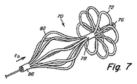
[0050] 図5〜図8に示すように、オクルーダ70は、図5の切断パターンによる管の遠位部分内のスリット74により形成される遠位ペタル72を形成する(押し出したり、圧延することができる)管から形成される。図6に示すように、管の遠位部分20は、ペタル72の遠位ループを形成している管の8つの延長セグメントを形成している8つのスリット74を含む。図を見れば分かるように、スリットは、同じ断面のループが形成されるように、中心管78と遠位端部76との間の管の遠位部分の全長にわたって延びる。遠位端部76に力Fdを加えると、スリット74により形成されている延長セグメントは、オクルーダ70の遠位側で遠位ペタル72を形成するために下に曲がり、外側に捻れる。展開中のセグメントの動きは、装置の軸に対して直角な面内でセグメントが回転するような動きである。中心管78は、力Fdが加わっている間、束縛することもできるし、又は管の軸方向の長さを短くするのに十分な力の組合せを加えることもできる。遠位の各ペタル72の一方の端部は、中心管78から始まり、他方の端部は、遠位端部76から始まる(図6及び図7)。近位ペタル82は、図6〜図8に示すように、近位部分40内に形成することができ、中心管78と近位端部86との間にスリット84を形成し、上記同じ切断パターンを使用し、オクルーダ70の近位部分40内に近位ペタル82を形成するように、スリット84が下に曲がり、外側に捻れることができるように、管の軸方向の長さを短くするのに十分な力Fp又は力の組合せを加える。遠位の各ペタル82の一方の端部は、中心管78から始まり、他方の端部は近位端部86から始まる。他の実施形態の場合には、オクルーダ70は、管状の形を形成するために、縦軸を中心にして半径方向に等距離に配置されているフィラメントから形成することができ、次に、端部及び中心で結合するために選択した位置のところで接着することができる。
[0050] As shown in FIGS. 5-8, the
[0051] オクルーダ70を形成している管又はフィラメントは、生体適合性金属又はポリマーから形成することができる。少なくともある実施形態には、オクルーダ70は生体吸収性ポリマー又は形状記憶ポリマーから形成される。装置の構造がPFOトンネルを押して閉鎖するのを補助するように、形状記憶ポリマーが有利な場合がある。他の実施形態の場合には、オクルーダ70は、形状記憶合金(例えば、ニチノール)のような生体適合性金属で形成される。形状記憶ポリマー及び合金の熱形状記憶及び/又は超弾性特性により、オクルーダ70は、送達プロセス中に捻れた場合でも、生体内でその意図する形状を回復し、維持することができる。代替的又は追加的に、オクルーダ70は、鉄、マグネシウム、又はこれら及び類似の材料の組合せのような生体吸収性金属から形成することができる。例示としての生体吸収性ポリマーは、ポリ水酸化アルカノエート組成、例えば、ポリ−4−ヒドロキシブチレート(P4HB)組成を含み、これは「Polyhydroxyalkanoate Compositions Having Controlled Degradation Rate」と題した米国特許第6,610,764号及び「Medical Devices and Applications of Polyhydroxyalkanoate Polymers」と題した米国特許第6,548,569号に開示されている。両方とも参照により全体を本明細書に組み込むものとする。
[0051] The tube or filament forming the
[0052] 管の断面形状は、円形であっても、例えば、四角形又は六角形のような多角形であってもよい。スリット74及び84は、多角形の面(すなわち、平坦な部分)上、又は面の交点上に配置することができる。
[0052] The cross-sectional shape of the tube may be circular or may be a polygon such as a square or a hexagon. The
[0053] 管は射出成形、押出成形、又は材料のシートで組み立て、管に丸めることもできる。材料のシートは、単層シートであってもよいし、又は多層であってもよい。シートを丸めて管にする前に、セグメントを形成するスリットを切断するか、打ち抜き加工し、端部を接続して閉じた断面を形成することができる。円形、四角形、六角形及び八角形などの種々の幾何学的断面が可能であり、継手は、断面が特定の幾何学的形状である場合、頂点にあっても、又は壁の平坦部分に沿って位置していてもよい。溶接、熱接着、非熱接着、及び生体内での用途に適している他の結合技術など、種々の取り付け技術を使用して、シートの端部を結合し、管を形成することができる。 [0053] The tube may be injection molded, extruded, or assembled from a sheet of material and rolled into a tube. The sheet of material may be a single layer sheet or multiple layers. Prior to rolling the sheet into a tube, the slits forming the segments can be cut or stamped to connect the ends to form a closed cross section. Various geometric cross-sections are possible, such as round, square, hexagonal and octagonal, and the joint is at the apex or along the flat part of the wall if the cross-section is a specific geometric shape May be located. Various attachment techniques can be used to join the ends of the sheets to form the tube, such as welding, thermal bonding, non-thermal bonding, and other bonding techniques suitable for in vivo applications.
[0054] オクルーダ70を変形することができるように設計すると、オクルーダ70を、展開した高い輪郭を有する構成の代わりに、ロープロフィールの送達構成で送達することができ、容易に、すなわち軸方向の長さを短くすることにより変換することができる。さらに、この変換は、遠位端部76及び近位端部86の両方に力を加えることにより容易に行うことができる。例えば、オクルーダ70の遠位部分20及び近位部分40は、別々のステップ中に展開することもできるし、又はオクルーダ70の両方の遠位部分20及び近位部分40を、キャッチシステムと係合する前に(例えば、送達カテーテルから)露出し、キャッチ部材が係合する時に一緒に展開することもできる。本明細書においては、近位部分及び遠位部分という用語は、それぞれ、それぞれ遠位側及び近位側に形成されるループ又は他の幾何学的形状及び構成を含む。
[0054] Designed to allow the
[0055] オクルーダ70は、いくつかの方法の中の任意の方法で作ることができる。スリット74及び84は、管が、生体内での展開の後で意図する形状に曲がるように切断することができる。より詳細には、スリット74及び84は、展開中に力Fd及び/又はFpを加えた場合に、(図7、図8に示すように)ループ72及び82の曲げ及び形成を容易にする厚さの(図5、図6に示すように)セグメント72及び82を形成するように切断することができる。ループを形成しているセグメント72及び82は、同じ参照符号がついている。代替的に又は追加的に、形状記憶材料からできている管を、生体内で展開した場合に、予め形成した形状に戻るように、生体外でその意図する形状に予め形成することができる。少なくともある実施形態の場合には、この予備形成技術を使用すれば、生体内でオクルーダ70をより高い信頼性で展開し、曲げることができる。中間的なアプローチも使用することができる。すなわち、力Fd及び/又はFpを加えた場合に、生体内で意図する形状に曲がるように予め設置するために、生体外で管を若干予め形成することができる。これらの技術は、また、フィラメントを一緒に接着することにより装置を形成する場合にも使用することもできる。
[0055] The
[0056] 図示及び説明のために、特定のタイプのオクルーダ70及び送達手順について説明する。もちろん、他のタイプのオクルーダも、本明細書に記載する展開キャッチシステムを使用して展開することができる。図8に示すペタルの構成は、展開した場合の構成である。オクルーダ70は、管の端部を一緒に保持するキャッチシステムにより、ペタル構成に固定することができる。そのいくつかの実施形態については、以下に説明する。
[0056] For purposes of illustration and description, a particular type of
[0057] 通常、本明細書においては、「オクルーダ70」という用語は、例えば、別々に列挙されたり、別段の指示がない限り、前後関係によりキャッチ部材50(又は50a)を含むことができる。キャッチ部材50は、図に示すように、オクルーダ70内の半径方向の中央の位置内の軸方向通路内に位置していて、オクルーダ70の別々の部材として概略図示されている。好ましい実施形態の場合には、キャッチ部材は、オクルーダ70を形成している管の一方の端部に固定することができる。例えば、キャッチ部材の遠位端部に設置されるフランジ92は、オクルーダ70の遠位端部に固定することができる。好適には、管の近位端部であることが好ましい管の一方の端部は、キャッチ部材50(又は50a)(及び特にキャッチシステム)に対して移動することができるので、遠位及び近位ペタル72及び82は、送達構成から展開構成に変化することができる。管の内面は、オクルーダ70がその展開した構成で固定されるように、オクルーダ70の近位端部86が、キャッチ部材50(又は50a)の近位フラップの遠位面の上にくるまで、キャッチ部材50(又は50a)の上、特に近位端部の上をスライドすることができる。キャッチ部材50(又は50a)は、送達システムと協働し、例えば、図に示し、以下にさらに詳細に説明するねじ部を含む送達/取出システムに接続するための部分を含む。
[0057] Generally, in this specification, the term "
[0058] ここで図9〜図18Bを参照しながらキャッチシステムについて説明する。図9は、オクルーダ70の軸方向通路内に配置することができるキャッチ部材50である。キャッチ部材50は、オクルーダ70の遠位端部に配置される遠位フランジ92を含む。ある実施形態の場合には、キャッチ部材の遠位フランジ92は、オクルーダ70に固定される。他の実施形態の場合には、キャッチ部材50は、オクルーダ70に対して回転することができる。一実施形態の場合には、キャッチ部材50は、力Fd(例えば、図6参照)を加えた場合に、オクルーダ70の遠位端部が近位側に移動することができるようにする遠位棚部94を含む。通常、キャッチ部材50の軸方向の長さは約5〜30mmであり、直径は約0.5〜3mmである。円筒になっているが、種々の断面の形状を効果的に使用することができる。
Here, the catch system will be described with reference to FIGS. 9 to 18B. FIG. 9 is a
[0059] キャッチ部材50は、キャッチ本体95及びキャッチ面を形成するフラップ98を含む近位側96を含む。キャッチ本体95は、筒状又は管状をしている。ある実施形態の場合には、キャッチ本体95は、展開した場合、オクルーダ70の実質的に全長を延びる。フラップ98は、図11に示すように、キャッチ本体95から半径方向に突き出る。フラップタイプのキャッチシステムを使用しているキャッチシステムの動作については以下に詳細に説明する。本明細書においては、フラップ(例えば、フラップ98)は、複数のウィング(例えば、2、3、4、5、6又はそれ以上のウィング)を含むことができることを理解されたい。ウィングは、1つ又は複数のスロットで分離されていてもよいし、分離されていなくてもよい。フラップは、例えば、図11に示すように、キャッチ部材の周囲に連続している円周方向の領域を形成することができる。さらに図9を参照すると、フラップ98は、2つのウィング102、104及びキャッチ部材50の軸を通して横方向に延びる平面スロット106を含む。ウィング102及び104は、スロット106により分離していて、近位側の一部にはウィングは存在しない。スロット106の目的については以下に説明する。本発明のある実施形態の場合には、ウィング102及び104は、図10に示すように、若干直角方向からずれている。本発明の他の実施形態の場合には、ウィング102及び104の縁部は、図10に示すように、丸みが付けられている。図9は、また、送達システムにキャッチ部材50を固定するために使用する雌ねじ部108を示す(極細線で示す)。図10は、図9のキャッチ部材50の近位側96の拡大斜視図である。
[0059] The
[0060] 図11は、本発明のある態様によるフラップ96を含むキャッチ部材50の他の実施形態である。より詳細には、キャッチ部材50の近位側96は、キャッチ部材の近位端部から見た場合、楕円形をしているフラップ98を含む。本明細書にはいくつかの形状を示してあるが、フラップ98及びウィング102及び104は、円形、四角形又は多角形のような任意の適切な形状を有することができる。フラップ98及びその種々の形状は、以下に説明するように、種々の利点を提供することができる。
[0060] FIG. 11 is another embodiment of a
[0061] ある実施形態の場合には、フラップは、少なくとも約1から約2の厚さ/幅(w)比を有する。図11に示すように、幅は、フラップがキャッチ部材50のキャッチ本体95の直径を越えて延びる半径方向の距離であり、厚さは、キャッチ部材50の軸方向のフラップの延長距離である。好適な形状の場合には、厚さは約0.005インチ(約0.127cm)であってもよく、幅は約0.010インチ(約0.0254cm)であってもよい。ある実施形態の場合には、フラップ98は、曲げにより形が変わり、その後でもとの形にもどるようにフラップが変形することができる弾性材料からできている。変形可能なフラップ98の場合には、キャッチ部材50の本体95に対して、またオクルーダの軸方向通路の近位端部に対して、キャッチ部材50の近位端部のところの直径を大きくすることができる。
[0061] In certain embodiments, the flap has a thickness / width (w) ratio of at least about 1 to about 2. As shown in FIG. 11, the width is the radial distance that the flap extends beyond the diameter of the
[0062] 図12及び図13は、ウィング112及び114がある角度を有する外縁部を有するキャッチ部材50の他の実施形態である。本発明の他の実施形態の場合には、フラップは、またキャッチ部材50の全周を延びることができる。図12は、キャッチ部材50の近位側の詳細な斜視図であり、図13は、図12の13−13線に沿って切断した断面図である。図に示すように、ウィング112及び114は、ある角度で外側を向いている縁部116及び118を含む。ある角度を有する縁部116及び118は、特定のフラップの幅及び厚さと一緒に、本発明のキャッチ機構の制御を助けることができる。縁部116及び118は、また、直角方向からずれていてもよいし、又は円形であってもよいし、又は任意の他の適切な形状であってもよい。
[0062] FIGS. 12 and 13 are other embodiments of the
[0063] 図30A及び図30Bは、第1のセグメント506及び第2のセグメント504を有するフラップ502を含む、キャッチ部材50の他の実施形態の近位端部の側部斜視図であり、詳細な斜視図である。セグメント506及び504は、直角方向からずれているV字形のノッチ508及び510により分離している環状部材の一部である。ノッチ508及び510も、所与の用途に適している他の形状を有することができる。
[0063] FIGS. 30A and 30B are side perspective views of the proximal end of another embodiment of the
[0064] 図14は、キャッチ部材50に沿って切断した断面斜視図であり、本発明の一実施形態による丸みが付いた断面122及び124を含むフラップを示す。さらに、本発明の一実施形態の場合、フラップは、図10〜図13に示すように、キャッチ部材の近位の先端に設置することもできるし、又は図14に示すように、距離dだけキャッチ部材の近位の先端から後にずらすこともできる。
[0064] FIG. 14 is a cross-sectional perspective view cut along the
[0065] 本明細書に記載する実施形態を使用すれば、近位端部のところのオクルーダ70の通路の内径のような、オクルーダ70のある寸法に対してキャッチ部材50の近位端部の外径をもっと大きくすることができ、他の実施形態の場合には、その展開した構成にオクルーダ70をしっかりと保持するために、オクルーダ70の近位端部の外径に対してキャッチ部材50の近位端部の外径をもっと大きくすることができる。本明細書に記載する実施形態を使用すれば、また、オクルーダ70の近位端部をフラップ98上を遠位方向にスライドさせる適当な大きさの力を加えた場合に、同時に容易にオクルーダ70の展開を容易に行うことができる。展開力に対して固定力を増大することができる他の実施形態については以下にさらに説明する。
[0065] Using the embodiments described herein, the proximal end of the
[0066] 本明細書に記載するフラップ98を使用すれば、オクルーダの展開の容易さと、キャッチ部材の展開した構成での捕捉の安全性、及び従来の設計では達成できなかったオクルーダ70の展開した構成との間でバランスを取ることができる。
[0066] Using the
[0067] さらに、その相対的な厚さのために、右心房内の輪郭をもっと小さくすることができる。フラップの輪郭が縮小すると、右心房内の血液の流れの乱れによる血栓ができる恐れが少なくなる。 [0067] Furthermore, due to its relative thickness, the contour in the right atrium can be made smaller. When the flap outline is reduced, the risk of blood clots due to turbulence of blood flow in the right atrium is reduced.
[0068] オクルーダ70の送達の際のキャッチシステムの動作については、図15〜図18Bのところで説明する。図15は、フラップキャッチシステムによるオクルーダ70の送達の部分詳細図である。キャッチ部材50は、ねじ接続装置58により内部送達ワイヤ346に取り付けられる。図に示すように、送達ワイヤ346の遠位端部上の雄ねじ部は、キャッチ部材50の近位端部上の雌ねじ部に嵌め込まれる。雌ねじ部は、また、オクルーダ70の全長に沿って他の場所に設けることもできる。もちろん、本明細書に記載する任意のねじ接続装置も使用することもできるし、雄ねじ部と雌ねじ部とを交換することもできる。図15に示すように、オクルーダ70は、ねじ結合により送達カテーテル356に取り付けられる。図に示すように、オクルーダの近位端部86は、雄ねじ部を含んでいて、送達カテーテル356は、雌ねじ部を含んでいる。送達ワイヤ346及び送達カテーテル356は、キャッチ部材50の近位端部96の位置を、オクルーダ70の近位端部86に対して移動することができるように操作することができる。オクルーダ70の展開中、キャッチ部材50の近位端部96は、オクルーダ70の近位端部86の方向に引っ張られる。オクルーダ70の近位端部86の内径は、キャッチ部材50のキャッチ本体95の外径より若干大きくすることができるが、キャッチ本体95の直径とフラップ98の幅とを合わせたもの(又はキャッチ部材50の近位端部の全外径)より大きくすることはできない。図15に示すように、キャッチ部材50の近位端部96の全外径に対するオクルーダ70の内径の大きさのために、オクルーダ70がフラップ98上を安全な展開した構成に強制的にされた場合、フラップ98を遠位方向に強制的に曲げることになる。
[0068] The operation of the catch system during delivery of the
[0069] 特に好ましい実施形態の場合には、フラップ98を含むキャッチ部材50の近位端部の全外径は、約0.090インチ(約0.229cm)であり、オクルーダ70の近位端部の内径は約0.070インチ(約0.178cm)である。オクルーダは、(図15に示すように)フラップ98が内部を移動した場合に、ある程度の半径方向及び/又は軸方向に変形(例えば、拡張)することができる材料から作ることができる。代替的に、オクルーダ70は、フラップ98が内部を移動した場合に、半径方向及び軸方向に全然弾力を持たない材料から作ることができる。図16は、オクルーダを通して移動した場合に、変形を起こしているフラップ98を軸方向から見た図である。
[0069] In a particularly preferred embodiment, the overall outer diameter of the proximal end of the
[0070] 図17は、キャッチ部材50全体がオクルーダ70を通って移動し、フラップがオクルーダ70の近位端部上に位置した後の、オクルーダ70及びキャッチ部材50の構成である。キャッチ部材50は、展開した構成でオクルーダと係合し、それを保持する。この構成の場合、フラップ98及びオクルーダ70の相対位置が図に示すような位置になった場合、送達ワイヤ346及びカテーテル356は、依然としてキャッチ部材及びオクルーダの位置をそれぞれ保持し、これにより、(例えば、X線透視法により)オクルーダ70の位置を見ることができ、オクルーダ70が所望の位置にあるか否かを確認することができる。一実施形態の場合には、図17に示すように、フラップ98を含むキャッチ部材50の近位端部の全外径は、送達カテーテル356の遠位部分より小さい。一実施形態の場合には、図17に示すように、フラップ98の寸法を、オクルーダ70がキャッチシステムが係合した状態で全開した場合に、フラップ98がオクルーダ70の近位端部86の近位側の面上に載るような大きさにすることができる。開示の実施形態の場合には、フラップ98は、オクルーダ70を展開した状態で変形を起こさずに保持するだけの十分な半径方向の強度を有する。
FIG. 17 shows the configuration of the
[0071] 図18A及び図18Bは、キャッチ部材50が、オクルーダ70の軸方向通路内に戻りつつある場合の、オクルーダ70を回収している際のオクルーダ70及びキャッチ部材50の構成を示す。図18Bは、オクルーダ70の近位端部の軸方向通路内にフラップ98が移動した場合の詳細図である。開示の実施形態の場合には、フラップ98は、装置を回収することができるように、オクルーダの軸方向通路(又はフラップ上の引き出されるオクルーダの軸方向通路)内に戻ることができる十分な柔軟性を有する。本発明のある実施形態の場合には、図18Bに示すように、フラップ98は、回収するために近位方向に曲がる。本発明の他の実施形態の場合には、図15に示すように、フラップ98は、送達のために遠位方向に曲がる。
18A and 18B show the configurations of the
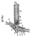
[0072] 所望の位置へのオクルーダの展開は、通常、複数のステップからなる動作である。図5〜図8の場合には、オクルーダ70は、説明上の都合で送達カテーテルの外部に位置する。図19に示すように、送達シース342は、その縮小した輪郭内に両方のオクルーダ70を含み、キャッチ部材50から切り離されている。図3及び図4のところですでに説明したように、囲まれているオクルーダ70を含む送達シース342(図3及び図4に示す送達アセンブリ124の一部)の遠位端部は、患者の心臓の右心房11内に最初に挿入される。次に、囲まれているオクルーダ70を含む送達シース342の遠位端部は、中隔組織12内に位置する解剖学的開口部18aを通して左心房13内に挿入される。次に、オクルーダ70の遠位端部20が、左心房13内に展開される。この展開プロセスについては以下にさらに説明する。
[0072] The expansion of the occluder to a desired position is usually an operation composed of a plurality of steps. In the case of FIGS. 5-8, the
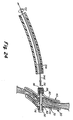
[0073] 図20に示すように、オクルーダ70の遠位端部20は、左心房13内で展開し、そのためオクルーダ70の中心管78は、解剖学的開口部18a内に位置する。図21に示すように、次に、オクルーダ70の近位部分40は、右心房11内に展開する。適正に展開した場合、中心管は、通常、解剖学的開口部18aのところに配置され、遠位部分20及び近位部分40は、図22に示すように、解剖学的開口部18a(例えば、PFO)を閉鎖するために、左心房13内の1次中隔14及び右心房11内の2次中隔16をそれぞれ圧縮する。図23〜図24に示すように、オクルーダ70が適正に展開した場合には、送達システムは、オクルーダ70から切り離され、送達カテーテル356及び送達ワイヤ346を含む送達シース342は心臓から後退させる。オクルーダ70が、上記手順を行った後で適正に展開しなかった場合には、オクルーダ70を送達手順のステップを逆にして取り出すことができる。
[0073] As shown in FIG. 20, the
[0074] 再度図19を参照すると、キャッチ部材50及びオクルーダ70は、それぞれ送達ワイヤ346及び送達カテーテル356に固定される。送達カテーテル356の雌ねじ部は、オクルーダ70の雄ねじ部に嵌め込まれる。送達ワイヤ346の雄ねじ部は、キャッチ部材50の雌ねじ部に嵌め込まれる。
[0074] Referring again to FIG. 19,
[0075] ここで図20を参照すると、オクルーダ70の遠位部分20は、左心房13内の遠位側で展開する。遠位部分20は、オクルーダ70の遠位部分20を露出するために、送達シース342の最初の後退動作により展開する。次に、オクルーダ70の軸方向の長さは、オクルーダ70の中心管78及びオクルーダ70の遠位部分20を引っ張る(フラップ98を含む)キャッチ部材の近位端部を圧縮し、遠位ペタル72を形成するのに十分な力で、送達ワイヤ346に引っ張り力F1を加えることにより短くなる。オクルーダ70を移動しないように保持するために、力F2が同時に送達カテーテル356に加えられる。オクルーダ70の中心管78は、キャッチ部材50のフラップ98上にきて、一時的に固定する。この一時的な固定により、展開手順の残りの手順が行われている間に、遠位ペタル72が所定の位置に保持される。
Referring now to FIG. 20, the
[0076] ここで図21を参照すると、オクルーダ70の近位部分40は、右心房11内の開口部の近位側で展開する。この展開は、オクルーダ70の近位部分40を露出するために、送達シース342の最初の後退動作により行われる。次に、近位ペタル82が、オクルーダ70の位置を維持するために、力F4を加えることにより送達カテーテル356前進させ、同時に力F5を加えることにより送達ワイヤ346を後退させることにより展開する。最後に、キャッチ部材50の近位端部が、オクルーダ70の近位端部の軸方向通路を通して引っ張られる。フラップ98は、図15及び図16に示すように、逆に変形する。より詳細には、キャッチ部材50上のフラップ98は、移動方向から遠ざかる方向に曲がる。フラップ98は、オクルーダ70の近位端部を越えて移動し、変形力がもはやフラップ98に加わらないので、フラップ98は、図17に示すように垂直方向に曲がる。図22は、最終的な構成を示し、フラップは図17に示す位置に位置する。この時点で、オクルーダ70が所望の位置に適正に展開したか否かを評価することができる。
Referring now to FIG. 21, the
[0077] オクルーダ70が、送達システムが取り付けられている状態で、又は少なくとも一部が取り外されている状態で、適正に展開したか否かについて評価することができる。オクルーダ70から送達カテーテル356を解放するか、又はキャッチ部材50から送達ワイヤ346を解放することにより、送達システムの一部を取り外すことができる。図23に示すように、1つの好ましい実施形態の場合には、オクルーダ70が適正に展開したか否かを評価するために、必要に応じて、送達シース342をさらに後退させることができ、また送達カテーテル356をオクルーダ70から取り外すことができる。送達カテーテル356は、オクルーダ70の近位のねじ部から螺脱させるためにトルクを加え、送達カテーテルを近位側に後退させることにより取り外すことができる。送達ワイヤ346は、図23に示すように、キャッチシステムを通してキャッチ部材50及びオクルーダ70を引き続き固定している。そのため、医者は、オクルーダ70の位置を評価するために、オクルーダの送達位置をほとんど遮るものなしで見ることができる。さらに、送達ワイヤ346の遠位部分がもっと柔軟で、送達ワイヤ346がもっと柔軟な場合には、視界が妨げられないように、送達システムの遠位端部及び展開したオクルーダ70を再度位置決めすることができる。オクルーダ70の位置は、X線透視法又は他の適切な技術により評価することができる。オクルーダ70の送達又は展開が十分でない場合には、送達システムをオクルーダ70を回収するために使用することができる。送達カテーテル356を取り外した場合には、送達カテーテルを、送達カテーテル356がオクルーダ70上に嵌め込まれるまで、送達カテーテル356をオクルーダ70のねじの近位部分の方向に近づけるように前進させ、トルクを加えることにより再度取り付けることができる。本発明の他の実施形態の場合には、送達カテーテル356は、オクルーダに取り付けられたままであり、一方、送達ワイヤ346は、展開を評価している間、取り外され、後退させられる。
[0077] It can be evaluated whether the
[0078] オクルーダ70がうまく展開すると、送達システムを図23〜図24に示す手順で取り外すことができる。図23に示すように、送達シース342は、力F12を加えることにより近位方向に後退させる。送達カテーテル356は、オクルーダ70のねじ部から送達カテーテル356のねじ部を外すために、トルクF14を加えることにより取り外される。次に、送達カテーテル356を近位側に後退させる。オクルーダ70は、送達ワイヤ346及びキャッチ部材50が提供する固定システムにより送達システムに取り付けられたままである。すでに説明したように、何らかの理由で回収したい場合には、オクルーダ70を、そのロープロフィールの構成に容易に戻し、この時点で取り外すことができる。図23に示すように、送達カテーテル356は、この場合も、送達ワイヤ346がキャッチ部材50に取り付けられたままで、オクルーダ70を何にも妨げられないで見ることができるようにさらに近位側に後退させることができる。図24に示すように、うまく展開できた場合には、送達ワイヤ346は、キャッチ部材50のねじ部から送達ワイヤ346のねじ部から螺脱させるために、トルクF17を加えることにより取り外すことができる。送達ワイヤ346及び送達カテーテル356を取り外すために加えるトルクは、設計次第でそれぞれ時計方向であっても、反時計方向であってもよい。キャッチ部材50から取り外した場合、送達ワイヤ346を近位方向に後退させることができる。この時点で、オクルーダ70は、完全に展開する。他の実施形態の場合には、送達カテーテル356は、評価が行われている間、オクルーダに取り付けられたままであり、一方、送達シース356及び送達ワイヤ346は、取り外され、近位方向に後退させられる。最終的解放を行っている間に、送達カテーテル356が最後に取り外される。
[0078] Once the
[0079] キャッチ部材50をオクルーダ70に対して回転できるようにオクルーダ70が設計されている場合には、すなわち、キャッチ部材50の遠位端部(例えば、遠位フランジ92)が、オクルーダ70の遠位端部に固定されていない場合には、キャッチ部材の近位端部上のスロット106、及び送達ワイヤ346上のスロット106と協働するブレード107(図15、図17及び図18Aに示す)を、キャッチ部材50が展開中回転するのを防止するために使用することができる。本発明の一実施形態の場合には、スロット106は、多くの形状及びサイズを有することができる。
[0079] If the
[0080] ここで図25を参照すると、送達ワイヤ346が依然としてキャッチ部材50に取り付けられている状態で、回収したい場合には、プロセスは、すでに説明したように、送達カテーテル356を再度取り付けるステップを含む。次に、フラップ98がオクルーダ70の近位端部の軸方向通路を強制的に通過するように、キャッチ部材50の近位端部96上をオクルーダ70の近位部分40を引っ張るために送達カテーテル356に力F6が加えられる。オクルーダ70の軸方向の長さが長くなると、近位ペタル82はまだ形をなしていないで、オクルーダ70の近位部分40は、その管状の輪郭に戻る。図26を参照すると、オクルーダ70の近位部分40上を送達シースを前進させ、オクルーダ70の近位部分20をロープロフィールの構成に維持するために、力F8が送達シース342に加えられる。また、オクルーダ70の遠位部分40を折り畳み、さらにオクルーダ70の軸方向の長さを長くするために、力F7が送達ワイヤ346に加えられる。代替的に、送達カテーテル356上を遠位方向に押すことにより、同じ結果が得られる。
[0080] Referring now to FIG. 25, if the
[0081] ここで図27を参照すると、オクルーダ70の遠位部分40が完全に元のロープロフィールの構成に戻り、オクルーダ70を送達シース内に戻すために、送達カテーテル356及び送達シース342に力F9及び力F10が加えられる。図28を参照すると、送達シース342及び閉鎖したオクルーダ70が解剖学的開口部18aから取り外され、力F11を加えることにより、心臓10からさらに完全に取り外すことができる。このステップも、オクルーダ70の再展開の出発点として使用することができる。
[0081] Referring now to FIG. 27, the
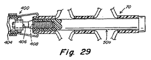
[0082] 図29は、今説明した本発明の他の実施形態を示す。図29は、送達システム内でオクルーダ70と係合しているキャッチ部材50aの部分図である。この実施形態の場合には、コレットシステム400が、送達カテーテル356にオクルーダ70を取り付けるために使用される。このシステムの詳細については、参照によりその全体を本明細書に組み込むものとする米国特許出願第11/235,661号に記載されている。この実施形態の場合には、キャッチ部材50aは、オクルーダ70の遠位端部に固定してもよいし、固定しなくてもよい。キャッチ部材50aが固定されていない場合には、(すでに説明した)ブレード及びスロットシステムを使用して、オクルーダに対してキャッチ部材を所望の向きに固定することができる。より詳細には、送達カテーテル404は、キャッチ部材50aのスロット408内に収まるブレード406を含む。ブレードシステムは、キャッチ部材の遠位側がオクルーダ70に対して回転することができる場合に特に有利である。ブレード406は、送達ワイヤ346をキャッチ部材50aから取り外すことができるようにスロット408内に嵌合する。
FIG. 29 shows another embodiment of the present invention just described. FIG. 29 is a partial view of the catch member 50a engaging the
[0083] 本発明のある実施形態は、必要な展開力と回収力が同じでない変形可能なフラップを含む。図31A及び図31Bは、本発明の他の実施形態によるキャッチ部材50の近位部分602を示す。近位部分602は、部材610a及び610bからなる変形可能なフラップ610を含む。これは1つのフラップ部材であってもよい。変形可能なフラップ610から遠位方向に延びるキャッチ部材604の一部は、キャッチ本体95の主要部分の直径であってもよい第1の直径(及びそれぞれ半径)を有する。変形可能なフラップ610から近位方向に延びるキャッチ部材606の一部は、第2の直径を有する。第2の直径は、第1の直径よりも大きい。この実施形態の場合には、回収中の、オクルーダ70の近位方向に曲がったフラップ610と軸方向通路との間の干渉は、送達の際のオクルーダ70の遠位方向に曲がったフラップ610と軸方向通路との間の干渉より大きい。この実施形態の場合には、特にキャッチ部材50を展開するのに必要な力と比較すると、装置を取り外すのに必要な力が大きくなる。ある他の実施形態の場合には、変形可能なフラップ610の他の寸法も、干渉を増大し、装置を取り外すのに必要な力を増大するようにすることもできる。
[0083] Certain embodiments of the invention include a deformable flap that does not have the same required deployment and recovery forces. 31A and 31B illustrate a
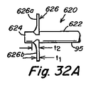
[0084] フラップ98の形状を、近位方向に曲げるのをもっと難しくし、したがって取り外したり、回収するのをもっと難しくするように変更することができる。図32A及び図32Bは、本発明の他の実施形態によるキャッチ部材50の近位部分620である。近位部分620は、部材626a及び626bからなる変形可能なフラップ626を含む。フラップ626も、ある実施形態の場合には、キャッチ本体の周囲を囲む1つの部材とすることができる。図32Aに示すように、フラップ626とフラップ626から遠位方向に延びるキャッチ部材622の一部との間の接合点での曲率半径は、フラップ626とフラップ626から近位方向に延びるキャッチ部材622の一部との間の曲率半径より小さい。それ故、一実施形態の場合には、変形可能なフラップ626は、外端部に第1の厚さt1を有し、変形可能なフラップ626がキャッチ部材50の本体と接合する基部にt1より薄い第2の厚さt2を有する。一実施形態の場合には、変形可能なフラップ626は、遠位側で直線状になっていて、近位側、特に基部のところでは湾曲している。他の実施形態の場合には、フラップ626の基部は、遠位側よりも近位側に大きな半径を有する。したがって、各変形可能なフラップ626a及び626bの基部は、近位側よりも厚い。それ故、オクルーダの送達中の遠位方向よりも、オクルーダの回収中に近位方向へフラップ626を曲げるために、より大きな力が必要になる。したがって、オクルーダ70を展開し、回収するのに必要な力は異なるものになり、変形可能なフラップ626が提供するキャッチは、特にしっかりしたものになり、一方、依然として容易に展開することができる。他の実施形態の場合には、類似の効果を得るために、フラップの形状を他の形に変えることができる。
[0084] The shape of the
[0085] 本明細書に記載する実施形態及び技術は、好適には、上記実施形態およ管が単一のモノリシックな材料であるか、又は管状構造に配置したフィラメントから形成されるように、ポリマーからできていて1つの管から形成されている装置と一緒に使用する場合について記述することが好ましい。キャッチ機構は、全部又は一部がモノリシックなものであってもよいし、管状構造と一体にすることもできるし、又は管状構造の残りの部分への任意のタイプの接着又はしっかりとした接続を使用しないですますこともできる。その場合、キャッチ機構を所定の位置に保持するためにある程度のスプリング力又は他の力を使用することもできる。それ故、図示の装置は、実質的に1つの管状本体から形成されているが、上記実施形態で説明したキャッチ機構は、多くの部品から形成したものを含み、金属、ポリマー、ステンレス鋼又はニチノールを含む他の材料から形成した装置を含む、他のタイプの装置と一緒に使用することができる。 [0085] The embodiments and techniques described herein are preferably such that the embodiments and tubes are formed from a single monolithic material or filaments disposed in a tubular structure. It is preferably described for use with an apparatus made of a polymer and formed from a single tube. The catch mechanism may be monolithic in whole or in part, may be integral with the tubular structure, or any type of adhesion or secure connection to the rest of the tubular structure. You can use it without using it. In that case, some spring force or other force may be used to hold the catch mechanism in place. Thus, although the illustrated apparatus is substantially formed from one tubular body, the catch mechanism described in the above embodiments includes those formed from a number of parts, such as metal, polymer, stainless steel, or nitinol. Can be used with other types of devices, including devices formed from other materials.
[0086] 上記説明で使用した「生体吸収性」という用語は、また、「生体再吸収性」を意味することも理解されたい。 [0086] It should also be understood that the term "bioabsorbable" used in the above description also means "bioresorbable".
[0087] 装置又はキャッチ部材がポリマーで作成される場合は、種々様々な結像技術でもっとはっきり見ることができるように放射線不透過性にするために、添加物を加えたりコーティングを行うことが望ましい場合がある。 [0087] If the device or catch member is made of a polymer, additives or coatings may be added to make it radiopaque so that it can be more clearly seen with a wide variety of imaging techniques. It may be desirable.
[0088] 説明のためにステップの特定の手順を図示し、説明してきたが、手順をいくつかの点で変更することもできるし、所望の展開を維持しながらある場合に特定の方法で展開するためにステップを組み合わせることができることを理解することができるだろう。例えば、送達シースを、種々の時間に及び種々の程度に前進させたり又は後退させることができ、オクルーダの近位部分及び遠位部分を、異なる手順等でペタル構成に展開することができる。さらに、ステップを自動化することもできる。 [0088] Although a specific procedure of steps has been illustrated and described for purposes of illustration, the procedure can be modified in several ways and deployed in a particular way, while maintaining a desired deployment. You will understand that you can combine steps to do that. For example, the delivery sheath can be advanced or retracted at various times and to various degrees, and the proximal and distal portions of the occluder can be deployed in a petal configuration, such as with different procedures. Furthermore, the steps can be automated.
[0089] 図の実施形態の詳細な説明は、説明のためだけのものであること、及び特許請求の範囲に記載する本発明の範囲から逸脱することなしに種々の変更を行うことができることを理解することができるだろう。 [0089] The detailed description of the illustrated embodiments is for illustrative purposes only, and various modifications can be made without departing from the scope of the invention as set forth in the claims. You will be able to understand.
Claims (22)
近位側及び遠位側と、
前記医療装置を前記第2の構成に保持するためのキャッチシステムであって、折り曲げることができるその近位端部にフラップを有するキャッチ部材を含み、前記フラップが前記医療装置を前記第2の構成に保持するキャッチシステムと、
を備える医療装置。 Folding to close the opening in the body, having a first configuration with a reduced profile and a second configuration with an expanded profile, configured to be delivered through a delivery system into a desired delivery location A medical device,
Proximal and distal sides;
A catch system for holding the medical device in the second configuration, comprising a catch member having a flap at a proximal end thereof that can be folded, wherein the flap holds the medical device in the second configuration. A catch system to hold on,
A medical device comprising:
前記フラップが、送達中に前記オクルーダの前記内部通路と第1の干渉を有し、回収中に前記オクルーダの前記内部通路と第2の干渉を有し、前記第2の干渉が前記第1の干渉より大きい、請求項1に記載の医療装置。 The flap is housed in the interior passage of the occluder during delivery and retrieval;
The flap has a first interference with the internal passage of the occluder during delivery, has a second interference with the internal passage of the occluder during retrieval, and the second interference is the first interference The medical device of claim 1, wherein the medical device is greater than the interference.
前記フラップから遠位方向に延びる前記キャッチ本体の第1の部分が、第1の外径を有し、
前記フラップから近位方向に延びる前記キャッチ本体が、第2の外径を有し、
前記第2の外径が前記第1の外径より大きい、請求項1に記載の医療装置。 The catch member includes a catch body;
A first portion of the catch body extending distally from the flap has a first outer diameter;
The catch body extending proximally from the flap has a second outer diameter;
The medical device according to claim 1, wherein the second outer diameter is larger than the first outer diameter.
近位側の前記キャッチ本体との接合点のところの前記フラップの基部が、湾曲していて、前記遠位側の前記フラップの基部より大きい半径を有する、請求項1に記載の医療装置。 The catch member includes a catch body;
The medical device according to claim 1, wherein a base of the flap at a junction with the proximal catch body is curved and has a larger radius than the base of the distal flap.
前記医療装置の全長に沿って延びる軸方向通路と、
キャッチ部材であって、前記通路内に前記キャッチ部材が位置している状態で、前記医療装置が、前記輪郭が縮小した構成から輪郭が拡張した構成に移動することができるように前記通路内に配置することができるキャッチ部材と、を備え、
前記キャッチ部材は、前記医療装置の近位端部に対して軸方向に移動することができる前記キャッチ部材の前記近位端部上にフラップを含み、
前記医療装置が輪郭が拡張した構成をしている場合に、前記軸方向通路の近くに配置される前記フラップが、前記医療装置を拡張した構成に固定する、医療装置。 Folding to close the opening in the body, having a first configuration with a reduced profile and a second configuration with an expanded profile, configured to be delivered through a delivery system into a desired delivery location A medical device,
An axial passage extending along the entire length of the medical device;
A catch member, wherein the medical device can move from a reduced profile configuration to an expanded profile configuration with the catch member positioned in the channel. A catch member that can be disposed,
The catch member includes a flap on the proximal end of the catch member that is axially movable relative to a proximal end of the medical device;
A medical device wherein the flap disposed near the axial passage secures the medical device in an expanded configuration when the medical device has an expanded configuration.
前記フラップが、送達中に前記医療装置の前記内部通路と第1の干渉を有し、回収中に前記医療装置の前記内部通路と第2の干渉を有し、前記第2の干渉が前記第1の干渉より大きい、請求項12に記載の医療装置。 The flap is housed in an internal passage of the medical device during delivery and retrieval;
The flap has a first interference with the internal passage of the medical device during delivery, has a second interference with the internal passage of the medical device during retrieval, and the second interference is the first interference. The medical device of claim 12, wherein the medical device is greater than one interference.
前記フラップから遠位方向に延びる前記キャッチ本体の第1の部分が、第1の外径を有し、
前記フラップが近位方向に延びる前記キャッチ本体の第2の部分が、第2の外径を有し、
前記第2の外径が前記第1の外径より大きい、請求項12に記載の医療装置。 The catch member includes a catch body;
A first portion of the catch body extending distally from the flap has a first outer diameter;
A second portion of the catch body in which the flap extends proximally has a second outer diameter;
The medical device according to claim 12, wherein the second outer diameter is larger than the first outer diameter.
前記近位側の前記キャッチ本体との接合点のところの前記フラップの基部が、湾曲していて、前記遠位側の前記フラップの基部より大きい半径を有する、請求項12に記載の医療装置。 The catch member includes a catch body;
13. The medical device of claim 12, wherein the base of the flap at the proximal junction with the catch body is curved and has a larger radius than the base of the distal flap.
Applications Claiming Priority (2)
| Application Number | Priority Date | Filing Date | Title |
|---|---|---|---|
| US78798806P | 2006-03-31 | 2006-03-31 | |
| PCT/US2007/065546 WO2007115125A2 (en) | 2006-03-31 | 2007-03-29 | Deformable flap catch mechanism for occluder device |
Publications (2)
| Publication Number | Publication Date |
|---|---|
| JP2009532125A true JP2009532125A (en) | 2009-09-10 |
| JP2009532125A5 JP2009532125A5 (en) | 2011-06-16 |
Family
ID=38475935
Family Applications (1)
| Application Number | Title | Priority Date | Filing Date |
|---|---|---|---|
| JP2009503288A Pending JP2009532125A (en) | 2006-03-31 | 2007-03-29 | Deformable flap catch mechanism for occluder equipment |
Country Status (5)
| Country | Link |
|---|---|
| US (1) | US8814947B2 (en) |
| EP (1) | EP2004068B1 (en) |
| JP (1) | JP2009532125A (en) |
| CA (1) | CA2647505C (en) |
| WO (1) | WO2007115125A2 (en) |
Cited By (2)
| Publication number | Priority date | Publication date | Assignee | Title |
|---|---|---|---|---|
| JP2017060800A (en) * | 2010-11-12 | 2017-03-30 | ダブリュ.エル.ゴア アンド アソシエイツ,インコーポレイティドW.L. Gore & Associates, Incorporated | Left atrial appendage obstructive device |
| JP2017526451A (en) * | 2014-09-12 | 2017-09-14 | カラク アーゲー | Occluder |
Families Citing this family (26)
| Publication number | Priority date | Publication date | Assignee | Title |
|---|---|---|---|---|
| AU5025600A (en) | 1999-05-17 | 2000-12-05 | Foxboro Company, The | Process control configuration system with parameterized objects |
| US8454652B1 (en) | 2002-10-29 | 2013-06-04 | Adam L. Cohen | Releasable tissue anchoring device, methods for using, and methods for making |
| US8480706B2 (en) | 2003-07-14 | 2013-07-09 | W.L. Gore & Associates, Inc. | Tubular patent foramen ovale (PFO) closure device with catch system |
| JP4917887B2 (en) | 2003-07-14 | 2012-04-18 | ダブリュー.エル.ゴア アンド アソシエイツ,インコーポレイテッド | Tubular patent foramen ovale (PFO) closure device with capture system |
| US9861346B2 (en) | 2003-07-14 | 2018-01-09 | W. L. Gore & Associates, Inc. | Patent foramen ovale (PFO) closure device with linearly elongating petals |
| US8992545B2 (en) * | 2006-09-28 | 2015-03-31 | W.L. Gore & Associates, Inc. | Implant-catheter attachment mechanism using snare and method of use |
| EP3329860A1 (en) | 2006-11-07 | 2018-06-06 | David Stephen Celermajer | Devices for the treatment of heart failure |
| US20110257723A1 (en) | 2006-11-07 | 2011-10-20 | Dc Devices, Inc. | Devices and methods for coronary sinus pressure relief |
| WO2008124603A1 (en) | 2007-04-05 | 2008-10-16 | Nmt Medical, Inc. | Septal closure device with centering mechanism |
| US20130165967A1 (en) | 2008-03-07 | 2013-06-27 | W.L. Gore & Associates, Inc. | Heart occlusion devices |
| US20120029556A1 (en) | 2009-06-22 | 2012-02-02 | Masters Steven J | Sealing device and delivery system |
| US9381006B2 (en) | 2009-06-22 | 2016-07-05 | W. L. Gore & Associates, Inc. | Sealing device and delivery system |
| US9636094B2 (en) | 2009-06-22 | 2017-05-02 | W. L. Gore & Associates, Inc. | Sealing device and delivery system |
| WO2012109557A2 (en) | 2011-02-10 | 2012-08-16 | Dc Devices, Inc. | Apparatus and methods to create and maintain an intra-atrial pressure relief opening |
| US9770232B2 (en) | 2011-08-12 | 2017-09-26 | W. L. Gore & Associates, Inc. | Heart occlusion devices |
| US9247930B2 (en) * | 2011-12-21 | 2016-02-02 | James E. Coleman | Devices and methods for occluding or promoting fluid flow |
| US10828019B2 (en) | 2013-01-18 | 2020-11-10 | W.L. Gore & Associates, Inc. | Sealing device and delivery system |
| US10376253B2 (en) * | 2013-08-07 | 2019-08-13 | The United States Of America, As Represented By The Secretary, Department Of Health And Human Services | Transvascular and transcameral device access and closure |
| WO2015165117A1 (en) * | 2014-04-30 | 2015-11-05 | 乐普(北京)医疗器械股份有限公司 | Medical closure system |
| US9808230B2 (en) | 2014-06-06 | 2017-11-07 | W. L. Gore & Associates, Inc. | Sealing device and delivery system |
| CN104274262B (en) * | 2014-09-01 | 2018-01-16 | 王垒 | For establishing the indwelling device of heart abnormality passage |
| WO2016153635A1 (en) * | 2015-03-24 | 2016-09-29 | Spiration, Inc.D/B/A Olympus Respiratory America | Airway stent |
| CN106580386B (en) * | 2016-12-15 | 2019-11-05 | 成都迪康中科生物医学材料有限公司 | A kind of absorbable uterine cavity sacculus |
| CN108685599B (en) * | 2017-04-06 | 2020-07-17 | 先健科技(深圳)有限公司 | Plugging device and plugging device |
| EP4084698A4 (en) * | 2020-01-24 | 2024-02-07 | Patchclamp Medtech Inc | Tissue repair and sealing devices having a detachable graft and clasp assembly and methods for the use thereof |
| US20210236102A1 (en) * | 2020-02-03 | 2021-08-05 | St. Jude Medical, Cardiology Division, Inc. | Occluder locking mechanisms |
Family Cites Families (238)
| Publication number | Priority date | Publication date | Assignee | Title |
|---|---|---|---|---|
| DE1445746A1 (en) | 1964-01-04 | 1969-03-20 | Bayer Ag | Process for the production of asymmetrical thiol or thionothiolphosphoric acid esters |
| US3874388A (en) * | 1973-02-12 | 1975-04-01 | Ochsner Med Found Alton | Shunt defect closure system |
| US3875648A (en) * | 1973-04-04 | 1975-04-08 | Dennison Mfg Co | Fastener attachment apparatus and method |
| US3824631A (en) | 1973-05-11 | 1974-07-23 | Sampson Corp | Bone joint fusion prosthesis |
| US3924631A (en) | 1973-12-06 | 1975-12-09 | Altair Inc | Magnetic clamp |
| US4006747A (en) * | 1975-04-23 | 1977-02-08 | Ethicon, Inc. | Surgical method |
| US4007743A (en) * | 1975-10-20 | 1977-02-15 | American Hospital Supply Corporation | Opening mechanism for umbrella-like intravascular shunt defect closure device |
| CH598398A5 (en) * | 1976-07-21 | 1978-04-28 | Jura Elektroapparate Fab | |
| US4425908A (en) * | 1981-10-22 | 1984-01-17 | Beth Israel Hospital | Blood clot filter |
| JPS6171065A (en) | 1984-09-13 | 1986-04-11 | テルモ株式会社 | Catheter introducer |
| US4696300A (en) | 1985-04-11 | 1987-09-29 | Dennison Manufacturing Company | Fastener for joining materials |
| US4626245A (en) | 1985-08-30 | 1986-12-02 | Cordis Corporation | Hemostatis valve comprising an elastomeric partition having opposed intersecting slits |
| US4710192A (en) | 1985-12-30 | 1987-12-01 | Liotta Domingo S | Diaphragm and method for occlusion of the descending thoracic aorta |
| EP0253365B1 (en) * | 1986-07-16 | 1991-11-27 | Sumitomo Chemical Company, Limited | Rubber composition |
| US4796612A (en) * | 1986-08-06 | 1989-01-10 | Reese Hewitt W | Bone clamp and method |
| US5478353A (en) | 1987-05-14 | 1995-12-26 | Yoon; Inbae | Suture tie device system and method for suturing anatomical tissue proximate an opening |
| US5250430A (en) | 1987-06-29 | 1993-10-05 | Massachusetts Institute Of Technology | Polyhydroxyalkanoate polymerase |
| US5245023A (en) | 1987-06-29 | 1993-09-14 | Massachusetts Institute Of Technology | Method for producing novel polyester biopolymers |
| US4836204A (en) | 1987-07-06 | 1989-06-06 | Landymore Roderick W | Method for effecting closure of a perforation in the septum of the heart |
| US4840623A (en) | 1988-02-01 | 1989-06-20 | Fbk International Corporation | Medical catheter with splined internal wall |
| IT1216042B (en) * | 1988-03-09 | 1990-02-22 | Carlo Rebuffat | AUTOMATIC TOOL FOR TOBACCO BAG SUTURES FOR SURGICAL USE. |
| US4902508A (en) * | 1988-07-11 | 1990-02-20 | Purdue Research Foundation | Tissue graft composition |
| US4956178A (en) | 1988-07-11 | 1990-09-11 | Purdue Research Foundation | Tissue graft composition |
| US4917089A (en) | 1988-08-29 | 1990-04-17 | Sideris Eleftherios B | Buttoned device for the transvenous occlusion of intracardiac defects |
| FR2641692A1 (en) * | 1989-01-17 | 1990-07-20 | Nippon Zeon Co | Plug for closing an opening for a medical application, and device for the closure plug making use thereof |
| US5245080A (en) | 1989-02-20 | 1993-09-14 | Jouveinal Sa | (+)-1-[(3,4,5-trimethoxy)-benzyloxymethyl]-1-phenyl-N,N-dimethyl-N-propylamine, process for preparing it and its therapeutical use |
| US5620461A (en) * | 1989-05-29 | 1997-04-15 | Muijs Van De Moer; Wouter M. | Sealing device |
| US5149327A (en) | 1989-09-05 | 1992-09-22 | Terumo Kabushiki Kaisha | Medical valve, catheter with valve, and catheter assembly |
| US5226879A (en) | 1990-03-01 | 1993-07-13 | William D. Ensminger | Implantable access device |
| DE69102515T2 (en) | 1990-04-02 | 1994-10-20 | Kanji Inoue | DEVICE FOR CLOSING A SHUTTER OPENING BY MEANS OF A NON-OPERATIONAL METHOD. |
| US5078736A (en) * | 1990-05-04 | 1992-01-07 | Interventional Thermodynamics, Inc. | Method and apparatus for maintaining patency in the body passages |
| US5021059A (en) | 1990-05-07 | 1991-06-04 | Kensey Nash Corporation | Plug device with pulley for sealing punctures in tissue and methods of use |
| US5037433A (en) | 1990-05-17 | 1991-08-06 | Wilk Peter J | Endoscopic suturing device and related method and suture |
| US20020032459A1 (en) * | 1990-06-20 | 2002-03-14 | Danforth Biomedical, Inc. | Radially-expandable tubular elements for use in the construction of medical devices |
| US5041129A (en) | 1990-07-02 | 1991-08-20 | Acufex Microsurgical, Inc. | Slotted suture anchor and method of anchoring a suture |
| WO1992005828A1 (en) * | 1990-10-09 | 1992-04-16 | Raychem Corporation | Device or apparatus for manipulating matter |
| JPH04170966A (en) | 1990-11-01 | 1992-06-18 | Nippon Sherwood Kk | Valvular body for catheter introducer blood stop valve |
| US5108420A (en) * | 1991-02-01 | 1992-04-28 | Temple University | Aperture occlusion device |
| US5257637A (en) | 1991-03-22 | 1993-11-02 | El Gazayerli Mohamed M | Method for suture knot placement and tying |
| CA2078530A1 (en) * | 1991-09-23 | 1993-03-24 | Jay Erlebacher | Percutaneous arterial puncture seal device and insertion tool therefore |
| EP0541063B1 (en) | 1991-11-05 | 1998-09-02 | The Children's Medical Center Corporation | Improved occluder for repair of cardiac and vascular defects |
| EP0545091B1 (en) | 1991-11-05 | 1999-07-07 | The Children's Medical Center Corporation | Occluder for repair of cardiac and vascular defects |
| US5282827A (en) * | 1991-11-08 | 1994-02-01 | Kensey Nash Corporation | Hemostatic puncture closure system and method of use |
| US5222974A (en) | 1991-11-08 | 1993-06-29 | Kensey Nash Corporation | Hemostatic puncture closure system and method of use |
| CA2128338C (en) | 1992-01-21 | 2004-10-12 | Gladwin S. Das | Septal defect closure device |
| US5486193A (en) * | 1992-01-22 | 1996-01-23 | C. R. Bard, Inc. | System for the percutaneous transluminal front-end loading delivery of a prosthetic occluder |
| US5316262A (en) | 1992-01-31 | 1994-05-31 | Suprex Corporation | Fluid restrictor apparatus and method for making the same |
| US5167363A (en) | 1992-02-10 | 1992-12-01 | Adkinson Steven S | Collapsible storage pen |
| US5411481A (en) | 1992-04-08 | 1995-05-02 | American Cyanamid Co. | Surgical purse string suturing instrument and method |
| US5236440A (en) | 1992-04-14 | 1993-08-17 | American Cyanamid Company | Surgical fastener |
| US5354308A (en) | 1992-05-01 | 1994-10-11 | Beth Israel Hospital Association | Metal wire stent |
| US5540712A (en) | 1992-05-01 | 1996-07-30 | Nitinol Medical Technologies, Inc. | Stent and method and apparatus for forming and delivering the same |
| DE4215449C1 (en) | 1992-05-11 | 1993-09-02 | Ethicon Gmbh & Co Kg, 2000 Norderstedt, De | |
| US5312341A (en) | 1992-08-14 | 1994-05-17 | Wayne State University | Retaining apparatus and procedure for transseptal catheterization |
| US5304184A (en) * | 1992-10-19 | 1994-04-19 | Indiana University Foundation | Apparatus and method for positive closure of an internal tissue membrane opening |
| US5275826A (en) * | 1992-11-13 | 1994-01-04 | Purdue Research Foundation | Fluidized intestinal submucosa and its use as an injectable tissue graft |
| US5417699A (en) | 1992-12-10 | 1995-05-23 | Perclose Incorporated | Device and method for the percutaneous suturing of a vascular puncture site |
| US5284488A (en) * | 1992-12-23 | 1994-02-08 | Sideris Eleftherios B | Adjustable devices for the occlusion of cardiac defects |
| US6346074B1 (en) * | 1993-02-22 | 2002-02-12 | Heartport, Inc. | Devices for less invasive intracardiac interventions |
| US5797960A (en) | 1993-02-22 | 1998-08-25 | Stevens; John H. | Method and apparatus for thoracoscopic intracardiac procedures |
| US5312435A (en) | 1993-05-17 | 1994-05-17 | Kensey Nash Corporation | Fail predictable, reinforced anchor for hemostatic puncture closure |
| US5350363A (en) | 1993-06-14 | 1994-09-27 | Cordis Corporation | Enhanced sheath valve |
| US5480424A (en) * | 1993-11-01 | 1996-01-02 | Cox; James L. | Heart valve replacement using flexible tubes |
| JP3185906B2 (en) * | 1993-11-26 | 2001-07-11 | ニプロ株式会社 | Prosthesis for atrial septal defect |
| US6334872B1 (en) * | 1994-02-18 | 2002-01-01 | Organogenesis Inc. | Method for treating diseased or damaged organs |
| DE69523615T3 (en) | 1994-04-06 | 2006-09-21 | William Cook Europe A/S | A MEDICAL DEVICE FOR IMPLANTING IN THE VASCULAR SYSTEM OF A HUMAN |
| US5853420A (en) | 1994-04-21 | 1998-12-29 | B. Braun Celsa | Assembly comprising a blood filter for temporary or definitive use and device for implanting it, corresponding filter and method of implanting such a filter |
| US6475232B1 (en) * | 1996-12-10 | 2002-11-05 | Purdue Research Foundation | Stent with reduced thrombogenicity |
| EP1217101B8 (en) | 1994-04-29 | 2006-02-01 | Boston Scientific Scimed, Inc. | Stent with collagen |
| US5601571A (en) * | 1994-05-17 | 1997-02-11 | Moss; Gerald | Surgical fastener implantation device |
| US5453095A (en) | 1994-06-07 | 1995-09-26 | Cordis Corporation | One piece self-aligning, self-lubricating catheter valve |
| US5725552A (en) * | 1994-07-08 | 1998-03-10 | Aga Medical Corporation | Percutaneous catheter directed intravascular occlusion devices |
| US5433727A (en) | 1994-08-16 | 1995-07-18 | Sideris; Eleftherios B. | Centering buttoned device for the occlusion of large defects for occluding |
| DE9413645U1 (en) | 1994-08-24 | 1994-10-27 | Schneidt Bernhard Ing Grad | Device for closing a duct, in particular the ductus arteriosus |
| US5577299A (en) | 1994-08-26 | 1996-11-26 | Thompson; Carl W. | Quick-release mechanical knot apparatus |
| US5618311A (en) * | 1994-09-28 | 1997-04-08 | Gryskiewicz; Joseph M. | Surgical subcuticular fastener system |
| US5879366A (en) | 1996-12-20 | 1999-03-09 | W.L. Gore & Associates, Inc. | Self-expanding defect closure device and method of making and using |
| US6171329B1 (en) * | 1994-12-19 | 2001-01-09 | Gore Enterprise Holdings, Inc. | Self-expanding defect closure device and method of making and using |
| US5702421A (en) | 1995-01-11 | 1997-12-30 | Schneidt; Bernhard | Closure device for closing a vascular opening, such as patent ductus arteriosus |
| FI108492B (en) * | 1995-01-20 | 2002-01-31 | Nokia Corp | Phone support |
| US5480353A (en) * | 1995-02-02 | 1996-01-02 | Garza, Jr.; Ponciano | Shaker crank for a harvester |
| US5634936A (en) | 1995-02-06 | 1997-06-03 | Scimed Life Systems, Inc. | Device for closing a septal defect |
| US5649959A (en) | 1995-02-10 | 1997-07-22 | Sherwood Medical Company | Assembly for sealing a puncture in a vessel |
| US5711969A (en) | 1995-04-07 | 1998-01-27 | Purdue Research Foundation | Large area submucosal tissue graft constructs |
| US5733337A (en) * | 1995-04-07 | 1998-03-31 | Organogenesis, Inc. | Tissue repair fabric |
| US6322548B1 (en) | 1995-05-10 | 2001-11-27 | Eclipse Surgical Technologies | Delivery catheter system for heart chamber |
| US6132438A (en) | 1995-06-07 | 2000-10-17 | Ep Technologies, Inc. | Devices for installing stasis reducing means in body tissue |
| DE69633411T2 (en) * | 1995-10-13 | 2005-10-20 | Transvascular, Inc., Menlo Park | METHOD AND DEVICE FOR PREVENTING ARTERIAL ATTRACTIONS AND / OR FOR CARRYING OUT OTHER TRANSVASCULAR INTERVENTIONS |
| EP0861049B1 (en) | 1995-10-30 | 2001-04-11 | Children's Medical Center Corporation | Self-centering umbrella-type septal closure device |
| US5717259A (en) * | 1996-01-11 | 1998-02-10 | Schexnayder; J. Rodney | Electromagnetic machine |
| DE19604817C2 (en) * | 1996-02-09 | 2003-06-12 | Pfm Prod Fuer Die Med Ag | Device for closing defect openings in the human or animal body |
| CA2197614C (en) | 1996-02-20 | 2002-07-02 | Charles S. Taylor | Surgical instruments and procedures for stabilizing the beating heart during coronary artery bypass graft surgery |
| US5733294A (en) * | 1996-02-28 | 1998-03-31 | B. Braun Medical, Inc. | Self expanding cardiovascular occlusion device, method of using and method of making the same |
| US5853422A (en) | 1996-03-22 | 1998-12-29 | Scimed Life Systems, Inc. | Apparatus and method for closing a septal defect |
| US5755791A (en) | 1996-04-05 | 1998-05-26 | Purdue Research Foundation | Perforated submucosal tissue graft constructs |
| AR001590A1 (en) * | 1996-04-10 | 1997-11-26 | Jorge Alberto Baccaro | Abnormal vascular communications occluder device and applicator cartridge of said device |
| US6488706B1 (en) | 1996-05-08 | 2002-12-03 | Carag Ag | Device for plugging an opening such as in a wall of a hollow or tubular organ |
| WO1997041778A1 (en) | 1996-05-08 | 1997-11-13 | Salviac Limited | An occluder device |
| US6143037A (en) | 1996-06-12 | 2000-11-07 | The Regents Of The University Of Michigan | Compositions and methods for coating medical devices |
| US5893856A (en) * | 1996-06-12 | 1999-04-13 | Mitek Surgical Products, Inc. | Apparatus and method for binding a first layer of material to a second layer of material |
| US5690674A (en) | 1996-07-02 | 1997-11-25 | Cordis Corporation | Wound closure with plug |
| US5800516A (en) | 1996-08-08 | 1998-09-01 | Cordis Corporation | Deployable and retrievable shape memory stent/tube and method |
| US6482224B1 (en) | 1996-08-22 | 2002-11-19 | The Trustees Of Columbia University In The City Of New York | Endovascular flexible stapling device |
| US5776183A (en) | 1996-08-23 | 1998-07-07 | Kanesaka; Nozomu | Expandable stent |
| US5741297A (en) * | 1996-08-28 | 1998-04-21 | Simon; Morris | Daisy occluder and method for septal defect repair |
| US5810884A (en) | 1996-09-09 | 1998-09-22 | Beth Israel Deaconess Medical Center | Apparatus and method for closing a vascular perforation after percutaneous puncture of a blood vessel in a living subject |
| US5861003A (en) * | 1996-10-23 | 1999-01-19 | The Cleveland Clinic Foundation | Apparatus and method for occluding a defect or aperture within body surface |
| US5944691A (en) | 1996-11-04 | 1999-08-31 | Cordis Corporation | Catheter having an expandable shaft |
| WO1998019719A1 (en) | 1996-11-05 | 1998-05-14 | Purdue Research Foundation | Myocardial graft constructs |
| CA2272097C (en) | 1996-12-10 | 2007-02-20 | Purdue Research Foundation | Artificial vascular valves |
| DE69724827T2 (en) * | 1996-12-10 | 2004-08-12 | Purdue Research Foundation, West Lafayette | TUBULAR TRANSPLANT CONSTRUCTIONS MADE OF SUBMUCOSAL TISSUE |
| US5776162A (en) | 1997-01-03 | 1998-07-07 | Nitinol Medical Technologies, Inc. | Vessel implantable shape memory appliance with superelastic hinged joint |
| JP3134287B2 (en) | 1997-01-30 | 2001-02-13 | 株式会社ニッショー | Catheter assembly for endocardial suture surgery |
| JP3134288B2 (en) | 1997-01-30 | 2001-02-13 | 株式会社ニッショー | Endocardial suture surgery tool |
| US5993844A (en) | 1997-05-08 | 1999-11-30 | Organogenesis, Inc. | Chemical treatment, without detergents or enzymes, of tissue to form an acellular, collagenous matrix |
| DE69837141T2 (en) | 1997-05-12 | 2007-10-31 | Metabolix, Inc., Cambridge | POLYHYDROXYALKANOATE FOR IN VIVO APPLICATIONS |
| US6610764B1 (en) | 1997-05-12 | 2003-08-26 | Metabolix, Inc. | Polyhydroxyalkanoate compositions having controlled degradation rates |
| US6867248B1 (en) * | 1997-05-12 | 2005-03-15 | Metabolix, Inc. | Polyhydroxyalkanoate compositions having controlled degradation rates |
| US6071292A (en) | 1997-06-28 | 2000-06-06 | Transvascular, Inc. | Transluminal methods and devices for closing, forming attachments to, and/or forming anastomotic junctions in, luminal anatomical structures |
| US6030007A (en) * | 1997-07-07 | 2000-02-29 | Hughes Electronics Corporation | Continually adjustable nonreturn knot |
| US5928260A (en) * | 1997-07-10 | 1999-07-27 | Scimed Life Systems, Inc. | Removable occlusion system for aneurysm neck |
| WO1999005209A1 (en) | 1997-07-22 | 1999-02-04 | Metabolix, Inc. | Polyhydroxyalkanoate molding compositions |
| US6828357B1 (en) | 1997-07-31 | 2004-12-07 | Metabolix, Inc. | Polyhydroxyalkanoate compositions having controlled degradation rates |
| US6174330B1 (en) * | 1997-08-01 | 2001-01-16 | Schneider (Usa) Inc | Bioabsorbable marker having radiopaque constituents |
| US6174322B1 (en) * | 1997-08-08 | 2001-01-16 | Cardia, Inc. | Occlusion device for the closure of a physical anomaly such as a vascular aperture or an aperture in a septum |
| US6077880A (en) | 1997-08-08 | 2000-06-20 | Cordis Corporation | Highly radiopaque polyolefins and method for making the same |
| WO1999014313A2 (en) | 1997-09-19 | 1999-03-25 | Metabolix, Inc. | Biological systems for manufacture of polyhydroxylalkanoate polymers containing 4-hydroxyacids |
| US5902319A (en) | 1997-09-25 | 1999-05-11 | Daley; Robert J. | Bioabsorbable staples |
| US6106913A (en) | 1997-10-10 | 2000-08-22 | Quantum Group, Inc | Fibrous structures containing nanofibrils and other textile fibers |
| US5989268A (en) | 1997-10-28 | 1999-11-23 | Boston Scientific Corporation | Endoscopic hemostatic clipping device |
| US5976174A (en) | 1997-12-15 | 1999-11-02 | Ruiz; Carlos E. | Medical hole closure device and methods of use |
| US5944738A (en) | 1998-02-06 | 1999-08-31 | Aga Medical Corporation | Percutaneous catheter directed constricting occlusion device |
| JP3799810B2 (en) * | 1998-03-30 | 2006-07-19 | ニプロ株式会社 | Transcatheter surgery closure plug and catheter assembly |
| US5993475A (en) | 1998-04-22 | 1999-11-30 | Bristol-Myers Squibb Co. | Tissue repair device |
| US6113609A (en) | 1998-05-26 | 2000-09-05 | Scimed Life Systems, Inc. | Implantable tissue fastener and system for treating gastroesophageal reflux disease |
| US6265333B1 (en) | 1998-06-02 | 2001-07-24 | Board Of Regents, University Of Nebraska-Lincoln | Delamination resistant composites prepared by small diameter fiber reinforcement at ply interfaces |
| US7452371B2 (en) | 1999-06-02 | 2008-11-18 | Cook Incorporated | Implantable vascular device |
| US6599302B2 (en) * | 1998-06-10 | 2003-07-29 | Converge Medical, Inc. | Aortic aneurysm treatment systems |
| US6328822B1 (en) * | 1998-06-26 | 2001-12-11 | Kiyohito Ishida | Functionally graded alloy, use thereof and method for producing same |
| US6165183A (en) | 1998-07-15 | 2000-12-26 | St. Jude Medical, Inc. | Mitral and tricuspid valve repair |
| US5919200A (en) | 1998-10-09 | 1999-07-06 | Hearten Medical, Inc. | Balloon catheter for abrading a patent foramen ovale and method of using the balloon catheter |
| US6183496B1 (en) | 1998-11-02 | 2001-02-06 | Datascope Investment Corp. | Collapsible hemostatic plug |
| US7713282B2 (en) * | 1998-11-06 | 2010-05-11 | Atritech, Inc. | Detachable atrial appendage occlusion balloon |
| US7044134B2 (en) | 1999-11-08 | 2006-05-16 | Ev3 Sunnyvale, Inc | Method of implanting a device in the left atrial appendage |
| US6152144A (en) | 1998-11-06 | 2000-11-28 | Appriva Medical, Inc. | Method and device for left atrial appendage occlusion |
| JP3906475B2 (en) * | 1998-12-22 | 2007-04-18 | ニプロ株式会社 | Transcatheter surgery closure plug and catheter assembly |
| US6371904B1 (en) * | 1998-12-24 | 2002-04-16 | Vivant Medical, Inc. | Subcutaneous cavity marking device and method |
| US6356782B1 (en) * | 1998-12-24 | 2002-03-12 | Vivant Medical, Inc. | Subcutaneous cavity marking device and method |
| US6228097B1 (en) | 1999-01-22 | 2001-05-08 | Scion International, Inc. | Surgical instrument for clipping and cutting blood vessels and organic structures |
| US6217590B1 (en) * | 1999-01-22 | 2001-04-17 | Scion International, Inc. | Surgical instrument for applying multiple staples and cutting blood vessels and organic structures and method therefor |
| WO2000051662A1 (en) * | 1999-03-04 | 2000-09-08 | Tepha, Inc. | Bioabsorbable, biocompatible polymers for tissue engineering |
| EP1163019B1 (en) * | 1999-03-25 | 2007-10-24 | Metabolix, Inc. | Medical devices and applications of polyhydroxyalkanoate polymers |
| DK1040843T3 (en) * | 1999-03-29 | 2006-01-30 | William Cook Europe As | A guidewire |
| US6277139B1 (en) | 1999-04-01 | 2001-08-21 | Scion Cardio-Vascular, Inc. | Vascular protection and embolic material retriever |
| US6277138B1 (en) * | 1999-08-17 | 2001-08-21 | Scion Cardio-Vascular, Inc. | Filter for embolic material mounted on expandable frame |
| US6379342B1 (en) * | 1999-04-02 | 2002-04-30 | Scion International, Inc. | Ampoule for dispensing medication and method of use |
| JP2000300571A (en) | 1999-04-19 | 2000-10-31 | Nissho Corp | Closure plug for transcatheter operation |
| US6206907B1 (en) * | 1999-05-07 | 2001-03-27 | Cardia, Inc. | Occlusion device with stranded wire support arms |
| US6379368B1 (en) * | 1999-05-13 | 2002-04-30 | Cardia, Inc. | Occlusion device with non-thrombogenic properties |
| US6712836B1 (en) * | 1999-05-13 | 2004-03-30 | St. Jude Medical Atg, Inc. | Apparatus and methods for closing septal defects and occluding blood flow |
| US6488689B1 (en) | 1999-05-20 | 2002-12-03 | Aaron V. Kaplan | Methods and apparatus for transpericardial left atrial appendage closure |
| US6426145B1 (en) | 1999-05-20 | 2002-07-30 | Scimed Life Systems, Inc. | Radiopaque compositions for visualization of medical devices |
| US6165204A (en) | 1999-06-11 | 2000-12-26 | Scion International, Inc. | Shaped suture clip, appliance and method therefor |
| US6494888B1 (en) | 1999-06-22 | 2002-12-17 | Ndo Surgical, Inc. | Tissue reconfiguration |
| US6306424B1 (en) | 1999-06-30 | 2001-10-23 | Ethicon, Inc. | Foam composite for the repair or regeneration of tissue |
| US6245080B1 (en) | 1999-07-13 | 2001-06-12 | Scion Cardio-Vascular, Inc. | Suture with toggle and delivery system |
| US6206895B1 (en) | 1999-07-13 | 2001-03-27 | Scion Cardio-Vascular, Inc. | Suture with toggle and delivery system |
| US6398796B2 (en) | 1999-07-13 | 2002-06-04 | Scion Cardio-Vascular, Inc. | Suture with toggle and delivery system |
| US7892246B2 (en) | 1999-07-28 | 2011-02-22 | Bioconnect Systems, Inc. | Devices and methods for interconnecting conduits and closing openings in tissue |
| US6231561B1 (en) | 1999-09-20 | 2001-05-15 | Appriva Medical, Inc. | Method and apparatus for closing a body lumen |
| US6551303B1 (en) | 1999-10-27 | 2003-04-22 | Atritech, Inc. | Barrier device for ostium of left atrial appendage |
| US6387104B1 (en) | 1999-11-12 | 2002-05-14 | Scimed Life Systems, Inc. | Method and apparatus for endoscopic repair of the lower esophageal sphincter |
| US6371971B1 (en) | 1999-11-15 | 2002-04-16 | Scimed Life Systems, Inc. | Guidewire filter and methods of use |
| US20010041914A1 (en) | 1999-11-22 | 2001-11-15 | Frazier Andrew G.C. | Tissue patch deployment catheter |
| US6790218B2 (en) * | 1999-12-23 | 2004-09-14 | Swaminathan Jayaraman | Occlusive coil manufacture and delivery |
| DE10000137A1 (en) | 2000-01-04 | 2001-07-12 | Pfm Prod Fuer Die Med Ag | Implantate for closing defect apertures in human or animal bodies, bearing structure of which can be reversed from secondary to primary form by elastic force |
| US6780197B2 (en) * | 2000-01-05 | 2004-08-24 | Integrated Vascular Systems, Inc. | Apparatus and methods for delivering a vascular closure device to a body lumen |
| US20010034567A1 (en) | 2000-01-20 | 2001-10-25 | Allen Marc L. | Remote management of retail petroleum equipment |
| FR2804567B1 (en) | 2000-01-31 | 2002-04-12 | St Microelectronics Sa | VIDEO PREAMPLIFIER |
| US6227139B1 (en) | 2000-03-16 | 2001-05-08 | The United States Of America As Represented By The Secretary Of The Navy | Control tab assisted lift reducing system for underwater hydrofoil surface |
| US7056294B2 (en) | 2000-04-13 | 2006-06-06 | Ev3 Sunnyvale, Inc | Method and apparatus for accessing the left atrial appendage |
| JP3844661B2 (en) * | 2000-04-19 | 2006-11-15 | ラディ・メディカル・システムズ・アクチェボラーグ | Intra-arterial embolus |
| US6214029B1 (en) * | 2000-04-26 | 2001-04-10 | Microvena Corporation | Septal defect occluder |
| US6551344B2 (en) | 2000-04-26 | 2003-04-22 | Ev3 Inc. | Septal defect occluder |
| US6352552B1 (en) * | 2000-05-02 | 2002-03-05 | Scion Cardio-Vascular, Inc. | Stent |
| US6599448B1 (en) | 2000-05-10 | 2003-07-29 | Hydromer, Inc. | Radio-opaque polymeric compositions |
| US6334864B1 (en) | 2000-05-17 | 2002-01-01 | Aga Medical Corp. | Alignment member for delivering a non-symmetric device with a predefined orientation |
| KR20040014389A (en) | 2000-07-21 | 2004-02-14 | 메타볼릭스 인코포레이티드 | Production of polyhydroxyalkanoates from polyols |
| US6440152B1 (en) | 2000-07-28 | 2002-08-27 | Microvena Corporation | Defect occluder release assembly and method |
| US6867249B2 (en) * | 2000-08-18 | 2005-03-15 | Kin Man Amazon Lee | Lightweight and porous construction materials containing rubber |
| CA2441866A1 (en) * | 2000-09-01 | 2002-09-07 | Onux Medical, Inc. | Endovascular fastener and grafting apparatus and method |
| US6364853B1 (en) * | 2000-09-11 | 2002-04-02 | Scion International, Inc. | Irrigation and suction valve and method therefor |
| US7169164B2 (en) * | 2000-09-21 | 2007-01-30 | Atritech, Inc. | Apparatus for implanting devices in atrial appendages |
| JP3722682B2 (en) * | 2000-09-21 | 2005-11-30 | 富士通株式会社 | Transmission device that automatically changes the type of transmission data within a specific band |
| US6699278B2 (en) | 2000-09-22 | 2004-03-02 | Cordis Corporation | Stent with optimal strength and radiopacity characteristics |
| NZ525519A (en) | 2000-09-25 | 2005-01-28 | Cohesion Tech Inc | Resorbable anastomosis stents for insertion into an opening in a lumen of a vessel or tissue of a patient |
| US6666861B1 (en) | 2000-10-05 | 2003-12-23 | James R. Grabek | Atrial appendage remodeling device and method |
| US6375625B1 (en) * | 2000-10-18 | 2002-04-23 | Scion Valley, Inc. | In-line specimen trap and method therefor |
| US6629901B2 (en) | 2000-11-09 | 2003-10-07 | Ben Huang | Composite grip for golf clubs |
| US6508828B1 (en) * | 2000-11-03 | 2003-01-21 | Radi Medical Systems Ab | Sealing device and wound closure device |
| US6746404B2 (en) | 2000-12-18 | 2004-06-08 | Biosense, Inc. | Method for anchoring a medical device between tissue |
| US20020128680A1 (en) | 2001-01-25 | 2002-09-12 | Pavlovic Jennifer L. | Distal protection device with electrospun polymer fiber matrix |
| US6550480B2 (en) | 2001-01-31 | 2003-04-22 | Numed/Tech Llc | Lumen occluders made from thermodynamic materials |
| US20020107531A1 (en) | 2001-02-06 | 2002-08-08 | Schreck Stefan G. | Method and system for tissue repair using dual catheters |
| US6623518B2 (en) | 2001-02-26 | 2003-09-23 | Ev3 Peripheral, Inc. | Implant delivery system with interlock |
| EP1365702A2 (en) * | 2001-03-08 | 2003-12-03 | Atritech, Inc. | Atrial filter implants |
| US6726696B1 (en) | 2001-04-24 | 2004-04-27 | Advanced Catheter Engineering, Inc. | Patches and collars for medical applications and methods of use |
| US20030004533A1 (en) * | 2001-05-04 | 2003-01-02 | Concentric Medical | Bioactive polymer vaso-occlusive device |
| US6921410B2 (en) | 2001-05-29 | 2005-07-26 | Scimed Life Systems, Inc. | Injection molded vaso-occlusive elements |
| US6537300B2 (en) | 2001-05-30 | 2003-03-25 | Scimed Life Systems, Inc. | Implantable obstruction device for septal defects |
| US7338514B2 (en) | 2001-06-01 | 2008-03-04 | St. Jude Medical, Cardiology Division, Inc. | Closure devices, related delivery methods and tools, and related methods of use |
| JP2005508208A (en) | 2001-06-04 | 2005-03-31 | アルバート・アインシュタイン・ヘルスケア・ネットワーク | Cardiac stimulator with thrombus filter and atrial pacemaker |
| US6585755B2 (en) | 2001-06-29 | 2003-07-01 | Advanced Cardiovascular | Polymeric stent suitable for imaging by MRI and fluoroscopy |
| US20030023266A1 (en) * | 2001-07-19 | 2003-01-30 | Borillo Thomas E. | Individually customized atrial appendage implant device |
| US7288105B2 (en) * | 2001-08-01 | 2007-10-30 | Ev3 Endovascular, Inc. | Tissue opening occluder |
| US6702835B2 (en) * | 2001-09-07 | 2004-03-09 | Core Medical, Inc. | Needle apparatus for closing septal defects and methods for using such apparatus |
| US6776784B2 (en) * | 2001-09-06 | 2004-08-17 | Core Medical, Inc. | Clip apparatus for closing septal defects and methods of use |
| US20070129755A1 (en) * | 2005-12-05 | 2007-06-07 | Ovalis, Inc. | Clip-based systems and methods for treating septal defects |
| US6596013B2 (en) * | 2001-09-20 | 2003-07-22 | Scimed Life Systems, Inc. | Method and apparatus for treating septal defects |
| AU2002360695A1 (en) | 2001-12-19 | 2003-07-09 | Nmt Medical, Inc. | Septal occluder and associated methods |
| US7318833B2 (en) | 2001-12-19 | 2008-01-15 | Nmt Medical, Inc. | PFO closure device with flexible thrombogenic joint and improved dislodgement resistance |
| US20030139819A1 (en) * | 2002-01-18 | 2003-07-24 | Beer Nicholas De | Method and apparatus for closing septal defects |
| CA2488337A1 (en) * | 2002-06-05 | 2003-12-18 | Nmt Medical, Inc. | Patent foramen ovale (pfo) closure device with radial and circumferential support |
| EP1556117A1 (en) | 2002-10-25 | 2005-07-27 | NMT Medical, Inc. | Expandable sheath tubing |
| AU2003287554A1 (en) | 2002-11-06 | 2004-06-03 | Nmt Medical, Inc. | Medical devices utilizing modified shape memory alloy |
| CA2503666A1 (en) | 2002-12-09 | 2004-06-24 | Nmt Medical, Inc. | Septal closure devices |
| CA2429314A1 (en) | 2003-05-22 | 2004-11-22 | Richard A. Dawson | Collapsible shield for smoking animal lure |
| JP2007528853A (en) * | 2003-07-08 | 2007-10-18 | テファ, インコーポレイテッド | Poly-4-hydroxybutyrate matrix for sustained release drug delivery |
| JP4917887B2 (en) * | 2003-07-14 | 2012-04-18 | ダブリュー.エル.ゴア アンド アソシエイツ,インコーポレイテッド | Tubular patent foramen ovale (PFO) closure device with capture system |
| US8480706B2 (en) * | 2003-07-14 | 2013-07-09 | W.L. Gore & Associates, Inc. | Tubular patent foramen ovale (PFO) closure device with catch system |
| US20050113868A1 (en) | 2003-11-20 | 2005-05-26 | Devellian Carol A. | Device, with electrospun fabric, for a percutaneous transluminal procedure, and methods thereof |
| US8764790B2 (en) | 2004-02-04 | 2014-07-01 | Carag Ag | Implant for occluding a body passage |
| US7871419B2 (en) * | 2004-03-03 | 2011-01-18 | Nmt Medical, Inc. | Delivery/recovery system for septal occluder |
| WO2005110240A1 (en) | 2004-05-07 | 2005-11-24 | Nmt Medical, Inc. | Catching mechanisms for tubular septal occluder |
| US7704268B2 (en) * | 2004-05-07 | 2010-04-27 | Nmt Medical, Inc. | Closure device with hinges |
| CA2581677C (en) * | 2004-09-24 | 2014-07-29 | Nmt Medical, Inc. | Occluder device double securement system for delivery/recovery of such occluder device |
| WO2006102213A1 (en) | 2005-03-18 | 2006-09-28 | Nmt Medical, Inc. | Catch member for pfo occluder |
| EP1962695A1 (en) | 2005-12-22 | 2008-09-03 | NMT Medical, Inc. | Catch members for occluder devices |
-
2007
- 2007-03-29 JP JP2009503288A patent/JP2009532125A/en active Pending
- 2007-03-29 CA CA2647505A patent/CA2647505C/en active Active
- 2007-03-29 EP EP07759737.5A patent/EP2004068B1/en active Active
- 2007-03-29 US US11/729,637 patent/US8814947B2/en active Active
- 2007-03-29 WO PCT/US2007/065546 patent/WO2007115125A2/en active Application Filing
Cited By (2)
| Publication number | Priority date | Publication date | Assignee | Title |
|---|---|---|---|---|
| JP2017060800A (en) * | 2010-11-12 | 2017-03-30 | ダブリュ.エル.ゴア アンド アソシエイツ,インコーポレイティドW.L. Gore & Associates, Incorporated | Left atrial appendage obstructive device |
| JP2017526451A (en) * | 2014-09-12 | 2017-09-14 | カラク アーゲー | Occluder |
Also Published As
| Publication number | Publication date |
|---|---|
| WO2007115125A9 (en) | 2008-06-12 |
| US8814947B2 (en) | 2014-08-26 |
| CA2647505A1 (en) | 2007-10-11 |
| US20070244517A1 (en) | 2007-10-18 |
| EP2004068B1 (en) | 2018-08-15 |
| WO2007115125A2 (en) | 2007-10-11 |
| WO2007115125A3 (en) | 2008-02-14 |
| CA2647505C (en) | 2014-07-29 |
| EP2004068A2 (en) | 2008-12-24 |
Similar Documents
| Publication | Publication Date | Title |
|---|---|---|
| JP2009532125A (en) | Deformable flap catch mechanism for occluder equipment | |
| EP2001368B1 (en) | Screw catch mechanism for pfo occluder | |
| US8430907B2 (en) | Catch member for PFO occluder | |
| US9084603B2 (en) | Catch members for occluder devices | |
| US8715319B2 (en) | Catch member for septal occluder with adjustable-length center joint | |
| US8109946B2 (en) | Adjustable length patent foramen ovale (PFO) occluder and catch system | |
| US8870913B2 (en) | Catch system with locking cap for patent foramen ovale (PFO) occluder | |
| US6436088B2 (en) | Method and apparatus for closing a subcutaneous tissue opening | |
| AU2007257785B2 (en) | Single disc occlusionary patent foramen ovale closure device | |
| EP2043527B1 (en) | Single disc intraluminal patent foramen ovale closure device | |
| JP2008514291A (en) | Double fixing system for delivery / recovery of occluder devices | |
| JP2007526087A (en) | Delivery / recovery system for septal occluder | |
| JP2009532124A (en) | Patent foramen ovale (PFO) closure device with linear extension petals | |
| WO2009143227A1 (en) | Tissue-piercing implants and other devices for treating septal defects |
Legal Events
| Date | Code | Title | Description |
|---|---|---|---|
| A521 | Request for written amendment filed |
Free format text: JAPANESE INTERMEDIATE CODE: A523 Effective date: 20100324 |
|
| A621 | Written request for application examination |
Free format text: JAPANESE INTERMEDIATE CODE: A621 Effective date: 20100324 |
|
| A072 | Dismissal of procedure [no reply to invitation to correct request for examination] |
Free format text: JAPANESE INTERMEDIATE CODE: A073 Effective date: 20110803 |