JP2009517213A - Multi-component liquid spray system - Google Patents
Multi-component liquid spray system Download PDFInfo
- Publication number
- JP2009517213A JP2009517213A JP2008543348A JP2008543348A JP2009517213A JP 2009517213 A JP2009517213 A JP 2009517213A JP 2008543348 A JP2008543348 A JP 2008543348A JP 2008543348 A JP2008543348 A JP 2008543348A JP 2009517213 A JP2009517213 A JP 2009517213A
- Authority
- JP
- Japan
- Prior art keywords
- component
- spray
- spray nozzles
- nozzles
- array
- Prior art date
- Legal status (The legal status is an assumption and is not a legal conclusion. Google has not performed a legal analysis and makes no representation as to the accuracy of the status listed.)
- Withdrawn
Links
Images


Classifications
-
- B—PERFORMING OPERATIONS; TRANSPORTING
- B05—SPRAYING OR ATOMISING IN GENERAL; APPLYING FLUENT MATERIALS TO SURFACES, IN GENERAL
- B05B—SPRAYING APPARATUS; ATOMISING APPARATUS; NOZZLES
- B05B7/00—Spraying apparatus for discharge of liquids or other fluent materials from two or more sources, e.g. of liquid and air, of powder and gas
- B05B7/02—Spray pistols; Apparatus for discharge
- B05B7/08—Spray pistols; Apparatus for discharge with separate outlet orifices, e.g. to form parallel jets, i.e. the axis of the jets being parallel, to form intersecting jets, i.e. the axis of the jets converging but not necessarily intersecting at a point
- B05B7/0884—Spray pistols; Apparatus for discharge with separate outlet orifices, e.g. to form parallel jets, i.e. the axis of the jets being parallel, to form intersecting jets, i.e. the axis of the jets converging but not necessarily intersecting at a point the outlet orifices for jets constituted by a liquid or a mixture containing a liquid being aligned
-
- B—PERFORMING OPERATIONS; TRANSPORTING
- B05—SPRAYING OR ATOMISING IN GENERAL; APPLYING FLUENT MATERIALS TO SURFACES, IN GENERAL
- B05B—SPRAYING APPARATUS; ATOMISING APPARATUS; NOZZLES
- B05B1/00—Nozzles, spray heads or other outlets, with or without auxiliary devices such as valves, heating means
- B05B1/14—Nozzles, spray heads or other outlets, with or without auxiliary devices such as valves, heating means with multiple outlet openings; with strainers in or outside the outlet opening
- B05B1/20—Arrangements of several outlets along elongated bodies, e.g. perforated pipes or troughs, e.g. spray booms; Outlet elements therefor
-
- B—PERFORMING OPERATIONS; TRANSPORTING
- B05—SPRAYING OR ATOMISING IN GENERAL; APPLYING FLUENT MATERIALS TO SURFACES, IN GENERAL
- B05B—SPRAYING APPARATUS; ATOMISING APPARATUS; NOZZLES
- B05B7/00—Spraying apparatus for discharge of liquids or other fluent materials from two or more sources, e.g. of liquid and air, of powder and gas
- B05B7/02—Spray pistols; Apparatus for discharge
- B05B7/04—Spray pistols; Apparatus for discharge with arrangements for mixing liquids or other fluent materials before discharge
- B05B7/0408—Spray pistols; Apparatus for discharge with arrangements for mixing liquids or other fluent materials before discharge with arrangements for mixing two or more liquids
-
- B—PERFORMING OPERATIONS; TRANSPORTING
- B05—SPRAYING OR ATOMISING IN GENERAL; APPLYING FLUENT MATERIALS TO SURFACES, IN GENERAL
- B05B—SPRAYING APPARATUS; ATOMISING APPARATUS; NOZZLES
- B05B7/00—Spraying apparatus for discharge of liquids or other fluent materials from two or more sources, e.g. of liquid and air, of powder and gas
- B05B7/02—Spray pistols; Apparatus for discharge
- B05B7/06—Spray pistols; Apparatus for discharge with at least one outlet orifice surrounding another approximately in the same plane
- B05B7/062—Spray pistols; Apparatus for discharge with at least one outlet orifice surrounding another approximately in the same plane with only one liquid outlet and at least one gas outlet
- B05B7/066—Spray pistols; Apparatus for discharge with at least one outlet orifice surrounding another approximately in the same plane with only one liquid outlet and at least one gas outlet with an inner liquid outlet surrounded by at least one annular gas outlet
Landscapes
- Nozzles (AREA)
- Application Of Or Painting With Fluid Materials (AREA)
Abstract
第1の成分の噴霧ノズルの第1の配列と、第2の成分の噴霧ノズルの第2の配列とを有する多成分液体噴霧システムを提供する。第1の成分の噴霧ノズルの各々は、第2の成分の噴霧ノズルのうちの少なくとも1つに隣接している。ノズルの共に一直線に並んだ直線配列及び平行に整列した直線配列を有する噴霧システムについて説明する。そのような噴霧システムを作る方法、並びに、多成分噴霧とコーティングされた物品の双方を作り出すために、それらの噴霧システムを使用する方法についても説明する。A multi-component liquid spray system is provided having a first array of first component spray nozzles and a second array of second component spray nozzles. Each of the first component spray nozzles is adjacent to at least one of the second component spray nozzles. A spray system having a linear array of nozzles aligned in parallel and a linear array aligned in parallel is described. Also described are methods for making such spray systems, as well as methods for using those spray systems to create both multi-component sprays and coated articles.
Description
本願は一般に、多成分液体噴霧システム、及び実質的に均一な比の第1の成分と第2の成分を基材の上に塗布する方法に関する。 The present application generally relates to multi-component liquid spray systems and methods of applying a substantially uniform ratio of first and second components onto a substrate.
本出願は、その全ての開示内容を参照によって本願に援用する、2005年12月1日に出願された米国特許仮出願番号60/748,233の利点を主張するものである。 This application claims the benefit of US Provisional Application No. 60 / 748,233, filed Dec. 1, 2005, the entire disclosure of which is incorporated herein by reference.
簡潔には、一態様において本開示は、ハウジング内の空洞によって画定されており、複数のオリフィスを備える部材によって1つの側部が境界を画されている空気チャンバと、第1の成分の噴霧ノズルの第1の配列であって、該第1の成分の噴霧ノズルの各々は、該部材内のオリフィスを貫いて突出している、第1の成分の噴霧ノズルの第1の配列と、第2の成分の噴霧ノズルの第2の配列であって、該第2の成分の噴霧ノズルの各々は、該部材内のオリフィスを貫いて突出している、第2の成分の噴霧ノズルの第2の配列と、を備えており、該第1の成分の噴霧ノズルの各々は、該第2の成分の噴霧ノズルのうちの少なくとも1つに隣接している、多成分液体噴霧システムを提供する。 Briefly, in one aspect, the present disclosure includes an air chamber defined by a cavity in a housing and bounded on one side by a member comprising a plurality of orifices, and a first component spray nozzle A first array of first component spray nozzles, each projecting through an orifice in the member; and a second array of first component spray nozzles; A second array of component spray nozzles, each of the second component spray nozzles projecting through an orifice in the member; and a second array of second component spray nozzles; Wherein each of the first component spray nozzles is adjacent to at least one of the second component spray nozzles.
いくつかの実施形態において、第1の成分の噴霧ノズルの第1の配列は第1の直線配列であり、第2の成分の噴霧ノズルの第2の配列は第2の直線配列である。いくつかの実施形態において、第1の成分の噴霧ノズルの第1の直線配列は、第2の成分の噴霧ノズルの第2の直線配列と共に一直線に並んでいる。いくつかの実施形態において、第1の成分の噴霧ノズルの第1の直線配列は、第2の成分の噴霧ノズルの第2の直線配列と平行である。いくつかの実施形態において、第2の成分の噴霧ノズルの各々は、それに最も近い第1の成分の噴霧ノズルから片寄っている。 In some embodiments, the first array of first component spray nozzles is a first linear array and the second array of second component spray nozzles is a second linear array. In some embodiments, the first linear array of first component spray nozzles is aligned with the second linear array of second component spray nozzles. In some embodiments, the first linear array of first component spray nozzles is parallel to the second linear array of second component spray nozzles. In some embodiments, each of the second component spray nozzles is offset from the closest first component spray nozzle.
いくつかの実施形態において、第1の成分の噴霧ノズルの各々は、主流れ軸と出口オリフィスとを備えており、第1の成分の噴霧ノズルのうちの少なくとも1つの出口オリフィスは、その主流れ軸に対してある角度で斜角を付けられて、斜面を形成している。いくつかの実施形態において、第2の成分の噴霧ノズルの各々は、主流れ軸と出口オリフィスとを備えており、第2の成分の噴霧ノズルのうちの少なくとも1つの出口オリフィスは、その主流れ軸に対してある角度で斜角を付けられて、斜面を形成している。いくつかの実施形態において、第1の成分の噴霧ノズルの斜面は、第2の成分の噴霧ノズルの斜面と共に収束している。 In some embodiments, each of the first component spray nozzles includes a main flow axis and an outlet orifice, and at least one of the first component spray nozzles has its main flow. Beveled at an angle to the axis to form a bevel. In some embodiments, each of the second component spray nozzles includes a main flow axis and an outlet orifice, and at least one of the second component spray nozzles has its main flow. Beveled at an angle to the axis to form a bevel. In some embodiments, the slope of the first component spray nozzle converges with the slope of the second component spray nozzle.
別の態様において、本開示は、ハウジング内の空洞によって画定されており、複数のオリフィスを備える部材によって1つの側部が境界を画されている空気チャンバと、第1の成分の噴霧ノズルの第1の配列であって、該第1の成分の噴霧ノズルの各々は、該部材内のオリフィスを貫いて突出している、第1の成分の噴霧ノズルの第1の配列と、第2の成分の噴霧ノズルの第2の配列であって、該第2の成分の噴霧ノズルの各々は、該部材内のオリフィスを貫いて突出している、第2の成分の噴霧ノズルの第2の配列と、第3の成分の噴霧ノズルの第3の配列であって、該第3の成分の噴霧ノズルの各々は、該部材内のオリフィスを貫いて突出している、第3の成分の噴霧ノズルの第3の配列と、を備えており、該第1の成分の噴霧ノズルの各々、及び該第3の成分の噴霧ノズルの各々は、該第2の成分の噴霧ノズルのうちの少なくとも1つに隣接している、多成分液体噴霧システムを提供する。 In another aspect, the present disclosure provides an air chamber defined by a cavity in a housing and bounded on one side by a member comprising a plurality of orifices and a first component spray nozzle. A first array of first component spray nozzles, each projecting through an orifice in the member, and a second component spray nozzle, wherein each of the first component spray nozzles projects through an orifice in the member. A second array of spray nozzles, each of the second component spray nozzles projecting through an orifice in the member; and a second array of second component spray nozzles; A third array of three component spray nozzles, each of the third component spray nozzles projecting through an orifice in the member, and a third of the third component spray nozzles. An array of spray nozzles of the first component S, and each of the spray nozzles of the components of the third, at least one of the spray nozzles the second component to the adjacent, provides a multi-component liquid spray system.
いくつかの実施形態において、第1の成分の噴霧ノズルの第1の配列は第1の直線配列であり、第2の成分の噴霧ノズルの第2の配列は第2の直線配列であり、第3の成分の噴霧ノズルの第3の配列は第3の直線配列である。いくつかの実施形態において、第1の成分の噴霧ノズルの第1の直線配列、第2の成分の噴霧ノズルの第2の直線配列、及び第3の成分の噴霧ノズルの第3の直線配列は、共に一直線に並んでいる。いくつかの実施形態において、第1の成分の噴霧ノズルの第1の直線配列は、第3の成分の噴霧ノズルの第3の直線配列と平行である。 In some embodiments, the first array of first component spray nozzles is a first linear array, the second array of second component spray nozzles is a second linear array, and The third array of three component spray nozzles is a third linear array. In some embodiments, the first linear array of first component spray nozzles, the second linear array of second component spray nozzles, and the third linear array of third component spray nozzles are: Both are in a straight line. In some embodiments, the first linear array of first component spray nozzles is parallel to the third linear array of third component spray nozzles.
更なる別の態様において、本開示は、多成分噴霧を生成する方法であって、第1の成分及び第2の成分を多成分液体噴霧システムに送達することと、該第1の成分の第1の噴霧を生成するために、第1の成分の噴霧ノズルの第1の配列を使用することと、該第2の成分の第2の噴霧を生成するために、第2の成分の噴霧ノズルの第2の配列を使用することと、該第1の噴霧の少なくとも第1の部分と第2の噴霧の少なくとも第2の部分とを混合させること、を含む方法を提供する。 In yet another aspect, the present disclosure is a method of generating a multi-component spray, delivering a first component and a second component to a multi-component liquid spray system, and a first component of the first component. Using a first array of first component spray nozzles to generate one spray and a second component spray nozzle to generate a second spray of the second component Using a second arrangement of: and mixing at least a first portion of the first spray and at least a second portion of a second spray.
別の態様において、本開示は、コーティングされた物品を作る方法であって、第1の成分及び第2の成分を多成分液体噴霧システムに送達するステップと、該第1の成分の第1の噴霧を生成するために、第1の成分の噴霧ノズルの第1の配列を使用するステップと、該第2の成分の第2の噴霧を生成するために、第2の成分の噴霧ノズルの第2の配列を使用するステップと、該第1及び第2の噴霧を物品に吹き付けるステップであって、少なくとも該第1の噴霧のうちの一部分と該第2の噴霧の一部分は、該物品に吹き付けられる前に混合されるステップと、を含む方法を提供する。 In another aspect, the present disclosure is a method of making a coated article comprising delivering a first component and a second component to a multi-component liquid spray system; and a first of the first component Using a first array of first component spray nozzles to generate a spray, and a second component spray nozzle first to generate a second spray of the second component. Using two arrangements and spraying the first and second sprays onto the article, wherein at least a portion of the first spray and a portion of the second spray are sprayed onto the article. Mixing before being done.
別の態様において、本開示は、多成分液体噴霧システムを作る方法であって、ハウジング内の空洞を形成することと、該空洞の境界を、複数のオリフィスを備える部材によって1つの側部において画すことと、第2の成分の噴霧ノズルの各々が該部材内のオリフィスを貫いて突出するように、第2の成分の噴霧ノズルの第2の配列を配置することと、第1の成分の噴霧ノズルの各々が該部材内のオリフィスを貫いて突出し、且つ該第2の成分の噴霧ノズルのうちの少なくとも1つに隣接するように、第1の成分の噴霧ノズルの第1の配列を配置すること、とを含む方法を提供する。 In another aspect, the present disclosure is a method of making a multi-component liquid spray system that defines a cavity in a housing and delimits the cavity on one side by a member that includes a plurality of orifices. Positioning a second array of second component spray nozzles such that each of the second component spray nozzles protrudes through an orifice in the member; and spraying the first component Positioning the first array of first component spray nozzles such that each of the nozzles protrudes through an orifice in the member and is adjacent to at least one of the second component spray nozzles. And a method comprising:
更に別の態様において、本開示は、ハウジング内の空洞によって画定された空気チャンバと、該ハウジングに結合された、第1の成分の第1の噴霧を生成するための手段と、該第1の噴霧を生成するための手段と流体連通した、該第1の成分を送達するための手段と、該ハウジングに結合された、第2の成分の第2の噴霧を生成するための手段と、該第2の噴霧を生成するための手段と流体連通した、該第2の成分を送達するための手段と、を備える多成分液体噴霧システムを提供する。 In yet another aspect, the present disclosure provides an air chamber defined by a cavity in a housing, means for generating a first spray of a first component coupled to the housing, and the first Means for delivering the first component in fluid communication with means for generating a spray; means for generating a second spray of a second component coupled to the housing; A multi-component liquid spray system comprising: means for delivering the second component in fluid communication with the means for generating a second spray.
本開示の上記の概要は、本発明の各実施形態を説明することを意図したものではない。また、本発明の1つ以上の実施形態の詳細を、以下の説明に記載する。本発明の他の特徴、目的、及び利点は、その説明から、また特許請求の範囲から明らかとなろう。 The above summary of the present disclosure is not intended to describe each embodiment of the present invention. The details of one or more embodiments of the invention are also set forth in the description below. Other features, objects, and advantages of the invention will be apparent from the description and from the claims.
多成分液体噴霧システムは、例えば幅広のウェブなどの、基材のコーティングを含む、様々な用途において有用である。いくつかの用途においては、多成分液体を、噴霧、即ち多量の分散液滴となって移動する材料として送達することが望ましい場合もある。多成分組成物を噴霧として送達する場合、例えば、成分の早期相互作用と、不適切な成分比、パージ要件、及び送達組成物の不均一性を含む、様々な要因により生産性が制限されることがある。 Multi-component liquid spray systems are useful in a variety of applications, including coating substrates, such as wide webs. In some applications, it may be desirable to deliver multi-component liquids as a material that travels as a spray, i.e., a large number of dispersed droplets. When delivering a multi-component composition as a spray, productivity is limited by a variety of factors including, for example, premature component interactions and improper component ratios, purge requirements, and non-uniformities in the delivery composition. Sometimes.
いくつかの多成分液体噴霧システムにおいて、種々の成分が、システムから送達されるのに先立って混合される。例えば、成分は、噴霧を生成するために使用されるノズルの上流側で混合されることがある。成分の早期相互作用は、成分のうちの2つ以上が噴霧システムを出る前に相互作用(例えば反応)し始める場合に発生する。成分の相互作用は、例えば、粘度の上昇(例えばゲル化)、及び/又は凝固につながることがあり、それによって、液体噴霧システムにおいて下流側の液体通路、例えばノズルが塞がることがある。 In some multi-component liquid spray systems, the various components are mixed prior to being delivered from the system. For example, the components may be mixed upstream of the nozzle used to generate the spray. An early interaction of components occurs when two or more of the components begin to interact (eg, react) before leaving the spray system. Component interactions can lead to, for example, increased viscosity (eg, gelation) and / or solidification, which can clog downstream liquid passages, eg, nozzles, in a liquid spray system.
多成分の混合物を噴霧するとき、成分比の誤差が起こりうる。多成分が、噴霧システムから排出されるのに先立って、望ましくない比で混合された場合、その不適切に混合された組成物は、噴霧システムからパージされなければならない。パージングは、時間及び材料を含む、資源を相当に浪費することにつながることが多い。また、パージング要件によって、望ましいコーティング組成物が変化し、例えば成分比が非効率で且つ不経済なものとなる。 When spraying multi-component mixtures, component ratio errors can occur. If the multi-component is mixed in an undesired ratio prior to being discharged from the spray system, the improperly mixed composition must be purged from the spray system. Purging often leads to considerable waste of resources, including time and materials. Also, purging requirements change the desired coating composition, for example, the component ratio is inefficient and uneconomical.
不均一な比の2つ以上の成分をウェブの幅全体にわたって送達しようと試みる場合、更なる問題が発生し得る。一般に、典型的な液体噴霧システムからの噴霧パターンは均一ではない。例えば、ウェブに送達される材料の量は、単一のノズルによって生成される噴霧の中央において又は縁部において、より多くなることがある。この不均一性は、多成分がノズルの上流側で混合される場合には許容されることがあるが、そのような不均一な噴霧は、複数のノズルによって生成された噴霧を組み合わせることによって、均一な成分比を達成しようと試みる場合には、許容されないことがある。同様に、ウェブの幅全体にわたって液体を供給するために、ノズルの配列が使用される場合、個々のノズルからの不均一な噴霧パターンは欠陥につながることがあり、ウェブの特定の領域に送達される液体の量が、ウェブの幅全体にわたって送達される液体の平均量よりも相当に多く又は少なくなり、結果として、例えば筋及びバンディングが生じ得る。 Additional problems can arise when attempting to deliver a non-uniform ratio of two or more components across the width of the web. In general, the spray pattern from a typical liquid spray system is not uniform. For example, the amount of material delivered to the web may be greater at the center or edge of the spray produced by a single nozzle. This non-uniformity may be tolerated when multiple components are mixed upstream of the nozzle, but such non-uniform spraying can be achieved by combining the sprays generated by multiple nozzles. When trying to achieve a uniform component ratio, it may not be acceptable. Similarly, when an array of nozzles is used to supply liquid across the width of the web, a non-uniform spray pattern from individual nozzles can lead to defects and be delivered to specific areas of the web The amount of liquid that is significantly greater or less than the average amount of liquid delivered across the width of the web can result in, for example, streaking and banding.
一態様において、本開示は、複数の成分を、その成分の一部が噴霧システムから排出されるまで互いに混合されないように送達することが可能な、多成分液体噴霧システムを提供する。いくつかの実施形態において、本開示の液体噴霧システムは、成分の早期相互作用を最小限にするか又は排除する。いくつかの実施形態において、本開示の液体噴霧システムは、パージング要件を緩和する。いくつかの実施形態において、本開示の液体噴霧システムは、多成分組成物の種々の成分の相対濃度を変化させるのに必要な時間及び/又は費用を減じる。別の態様において、本開示は、均一な比の2つ以上の成分を、物品、例えばウェブの幅全体にわたって送達することが可能な多成分液体噴霧システムを提供する。本開示の他の特徴及び利点について、以下で説明する。 In one aspect, the present disclosure provides a multi-component liquid spray system that is capable of delivering a plurality of components so that they are not mixed together until a portion of the components are discharged from the spray system. In some embodiments, the liquid spray system of the present disclosure minimizes or eliminates early interaction of components. In some embodiments, the liquid spray system of the present disclosure relaxes purging requirements. In some embodiments, the liquid spray system of the present disclosure reduces the time and / or cost required to change the relative concentrations of the various components of the multi-component composition. In another aspect, the present disclosure provides a multi-component liquid spray system that can deliver a uniform ratio of two or more components across the width of an article, eg, a web. Other features and advantages of the present disclosure are described below.
本開示の一実施形態の例示的な多成分液体噴霧システムを図1a〜1fに示す。一般に、ダイの各部品は、金属及びプラスチックなどの周知の材料から形成することができる。例示的な材料には、ステンレス鋼及びナイロンが挙げられる。各部品に使用する材料の選択は、当該技術分野に含まれるものである。用途に応じて、選択に影響を及ぼす要因には、噴霧される材料との適合性、製造の容易性、コスト、耐食性、耐摩耗性、熱安定性、及び耐久性が含まれてもよい。 An exemplary multi-component liquid spray system of one embodiment of the present disclosure is shown in FIGS. In general, each part of the die can be formed from well-known materials such as metal and plastic. Exemplary materials include stainless steel and nylon. Selection of materials to be used for each part is included in the art. Depending on the application, factors that affect selection may include compatibility with the material being sprayed, ease of manufacture, cost, corrosion resistance, wear resistance, thermal stability, and durability.
図1aを参照すると、多成分液体噴霧システム10が、ハウジング20と、第1の成分の噴霧ノズル50と、第2の成分の噴霧ノズル60とを備えている。ハウジング20はフロントパネル14を有しており、このフロントパネル14は、装着ボルト11によって供給ブロック(図示せず)に装着されている。多成分液体噴霧システム10はまた、第1の成分の入口ポート22と、第2の成分の入口ポート24と、空気入口ポート26とを有している。種々のポートの数及び位置の選択は、慣例の設計考慮事項の問題であり、例えば、送達される材料の特性(例えば密度及び粘度)、望ましい流量及び流動分布、噴霧システムの大きさ、ハウジング内での空間的制約(例えば、望ましい液体及び/又は空気の経路)、並びに、ハウジング外部での空間的制約(例えば、供給システム及び装着機構の望ましい位置)によって影響を受ける場合がある。
Referring to FIG. 1 a, a multi-component
図1bに示すように、フロントパネル14に加えて、ハウジング20は、各々が供給ブロック(図示せず)に装着ボルトによって取り付けられたサイドパネル12及びバックパネル13と、空気プレート40とを有している。各第1の成分の噴霧ノズル50及び第2の成分の噴霧ノズル60は、空気プレート40内のオリフィス42を貫いて突出している。オリフィス42は、円形オリフィスとして示されているが、例えば幾何学的形状(例えば、正方形、三角形、又は六角形)及び不規則形状を含むいかなる形状であってもよい。
As shown in FIG. 1b, in addition to the
図2を参照すると、位置合わせ機構144を有するオリフィス142を備える空気プレート140の一部分が示されている。一般に、位置合わせ機構144は、ノズルをオリフィスの中心に対して位置合わせするのを支援するように選択される。いくつかの実施形態において、ノズルをオリフィス内で同心的に位置決めすると望ましい場合もある。いくつかの実施形態において、ノズルをオリフィスの中心から片寄らせると望ましい場合もある。オリフィスごとの位置合わせ機構の寸法、形状、及び数の選択は、慣例の設計考慮事項であり、例えば、ノズルの寸法及び形状、ノズルの望ましい位置、並びに、ノズルが噴霧の間に受ける力(例えば空気圧力及び液体圧力)に依存する場合もある。
With reference to FIG. 2, a portion of an
いくつかの実施形態において、空気プレート内の開口部は、1つ以上の細長いオリフィス又はスロットを備えていていもよい。いくつかの実施形態において、1つのノズルのみが各オリフィスを貫いて突出している。いくつかの実施形態において、2つ以上のノズルが、単一のオリフィスを貫いて突出していてもよい。いくつかの実施形態において、ノズルが貫いて突出しないオリフィスが存在してもよい。 In some embodiments, the opening in the air plate may comprise one or more elongated orifices or slots. In some embodiments, only one nozzle protrudes through each orifice. In some embodiments, two or more nozzles may protrude through a single orifice. In some embodiments, there may be an orifice through which the nozzle does not protrude.
図1cを参照すると、多成分液体噴霧システム10の部分分解図が、フロントパネルを取り外した状態で示されている。バックパネル14は、空気プレート40の縁部を受けるための溝16を有している。同様の溝が、フロントパネル及びサイドパネル内に存在する。各溝16は、タブ17などの位置合わせ機構を有していてもよく、このタブ17は、凹部44など、空気プレート40内の対応する位置合わせ機構と嵌合する。溝16は、空気プレート40をノズルプレート70からの一定距離で支持して、空気チャンバ30を形成している。
Referring to FIG. 1c, a partially exploded view of multi-component
加圧空気が、空気入口ポート26を通じて空気チャンバ30に入る。いくつかの実施形態において、空気以外に、気体又は蒸気、例えば、酸素、窒素、二酸化炭素、及び水蒸気が使用されてもよい。空気チャンバ30は、一方の側部では空気プレート40によって境界を画されており、この空気プレート40は、空気チャンバ30から周囲環境中へと空気を通すオリフィス42を有する。空気チャンバ30は、対向する側部ではノズルプレート70によって境界を画されており、このノズルプレート70は、装着ボルト78によって供給ブロック90に装着されている。
Pressurized air enters the
図1dに示すように、噴霧ノズル50及び60は、ノズルプレート70の開口部72の中に圧入されている。ノズルをノズルプレート70の開口部内に取り付ける他の手段、例えば、ねじ付きの取り付け具、接着剤、及び硬化性材料(例えばエポキシ)を使用してもよい。
As shown in FIG. 1 d, the
図1c、1e及び1fを参照すると、ノズルプレート70の底面74は、ガスケット80によって供給ブロック90から分離されている。ノズルプレート70及びガスケット80は、装着ボルト78によって供給ブロック90に取り付けられている。一般に、ガスケット80は、ノズルプレート70と供給ブロック90の合わせ面における不完全部を補正する。これらの面が高度に研磨されており、且つ谷部及び/又は頂部がない場合、ガスケットはなくてもよい。しかしながら、高度に研磨された表面を有していても、いずれかの表面上のほこり又はくずが、完全な封止が形成されるのを妨げることがあり、また漏れが発生することもある。一般に、ガスケット80は、軟質金属(例えば銅)、高分子フィルム(例えばポリエステル若しくはナイロン)、シリコン、ゴム、又は、含浸織布若しくは不織布ウェブ(例えばゴム含浸織布)などの圧縮性材料でできている。
Referring to FIGS. 1 c, 1 e and 1 f, the
装着ボルト78を受けるためのスルーホール79を有する、ノズルプレート70の底面74が、図1eに示されている。開口部72により、第1の成分を含む液体と第2の成分を含む液体は、第1の成分の液体のノズル及び第2の成分の液体のノズルへと、それぞれ流れることができる。開口部72は、第1の凹部91と第2の凹部92との間に位置する。第1の凹部91は、供給ブロック内の対応する凹部と共に、第1の液体のマニホールドを形成する。同様に、第2の凹部92は、供給ブロック内の対応する凹部と合わせられると、第2の液体のマニホールドを形成する。これらの対応する凹部が図1fに示されている。
The
図1fを参照すると、供給ブロック90が第3の凹部93を備えており、この第3の凹部93は、ノズルプレート70内の第1の凹部91と共に、第1の液体のマニホールドを形成している。第3の凹部93はチャネル81を有する。ガスケット80は、対応するチャネル82を有しており、従って、ガスケット80が供給ブロック90上に適切に配置されると、チャネル81と82は一直線に並び、第1の液体のマニホールドから、第1の成分の噴霧ノズルに供給する、ノズルプレート70内の開口部72にのみ材料を導く通路を形成する。同様に、供給ブロック90は第4の凹部94を備えており、この第4の凹部は、ノズルプレート70内の第2の凹部92と共に、第2の液体のマニホールドを形成している。第4の凹部94はチャネル83を有している。ガスケット80は、対応するチャネル84を有しており、従って、ガスケット80が供給ブロック90上に適切に配置されると、チャネル83と84は一直線に並び、第2の液体のマニホールドから、第2の成分の噴霧ノズルに供給する、ノズルプレート70内の孔72にのみ材料を導く通路を形成する。
Referring to FIG. 1 f, the
一般に、第1の成分を含む第1の液体は、第1の液体のマニホールド内へと、第1の成分の入口ポートを通じて供給される。第1の液体は第1の液体のマニホールドを満たし、供給ブロック及びシム内のチャネルによって形成された通路の中を流れ、第1の成分の噴霧ノズルから吐出される。同様に、第2の成分を含む第2の液体は、第2の液体のマニホールド内へと、第2の成分の入口ポートを通じて供給され、その第2の液体のマニホールドを満たす。第2の液体は、供給ブロック及びシム内のチャネルによって形成された通路の中を流れ、第2の成分の噴霧ノズルから吐出される。空気(及び/又は他の気体若しくは蒸気)が、第1及び第2の成分の噴霧ノズルを囲むオリフィスを通じて、空気チャンバから流れる。この空気は、第1及び第2の液体が噴霧ノズルを出るとき、その第1及び第2の液体の微粒化を支援する。 In general, a first liquid containing a first component is fed into a first liquid manifold through a first component inlet port. The first liquid fills the first liquid manifold, flows through the passage formed by the channels in the supply block and shim, and is ejected from the first component spray nozzle. Similarly, the second liquid containing the second component is fed into the second liquid manifold through the second component inlet port and fills the second liquid manifold. The second liquid flows through a passage formed by a channel in the supply block and shim and is ejected from a second component spray nozzle. Air (and / or other gas or vapor) flows from the air chamber through an orifice surrounding the spray nozzles of the first and second components. This air assists atomization of the first and second liquids as the first and second liquids exit the spray nozzle.
いくつかの実施形態において、ノズル及びマニホールドの設計は、各マニホールドの長さの下方と比べて相当に大きな圧力降下が各ノズルの長さの下方に生じるように選択されている。いくつかの実施形態において、各第1のノズルの入口における圧力は、第1のマニホールドの長さに沿って実質的に一定であり、各第2のノズルの入口における圧力は、第2のマニホールドの長さに沿って実質的に一定である。第1のノズルの入口における圧力は、第2のノズルの入口における圧力と実質的に同じであっても異なっていてもよい。 In some embodiments, the nozzle and manifold design is selected such that a significantly greater pressure drop occurs below the length of each nozzle as compared to the length below each manifold. In some embodiments, the pressure at the inlet of each first nozzle is substantially constant along the length of the first manifold, and the pressure at the inlet of each second nozzle is the second manifold. Is substantially constant along the length of. The pressure at the inlet of the first nozzle may be substantially the same as or different from the pressure at the inlet of the second nozzle.
本開示の一実施形態の噴霧ノズルを、図3a及び3bに示す。ノズル100は、主流れ軸102と出口オリフィス104とを有する中空管を備えている。出口オリフィス104は、円形として示されている。一般に、出口オリフィスは、例えば楕円形、三角形、正方形、六角形、及び八角形を含めたいかなる横断面形状を有していてもよい。いくつかの実施形態において、不規則な形状の出口オリフィスが使用されてもよい。出口オリフィスの形状に関わらず、オリフィスの水力直径DHは、オリフィスの断面積Aの4倍を、オリフィスの濡れ縁長さPで割ったものとして定義される(即ち、DH=4A/P)。円形オリフィスの水力直径は、その円の直径に等しい。
A spray nozzle of one embodiment of the present disclosure is shown in FIGS. 3a and 3b. The
図3a及び3bに示すように、ノズル100の出口オリフィス104は、主流れ軸102と実質的に垂直である。いくつかの実施形態において、出口オリフィスは、主流れ軸に対して傾斜を付けられて、斜面を形成している。例えば、図4を参照すると、主流れ軸112に対して角度Xで斜角を付けられた出口オリフィス114を有するノズル110が示されている。一般に、いかなる斜角を使用してもよい。いくつかの実施形態においては、少なくとも15°の斜角が、またいくつかの実施形態においては、少なくとも20°、更には少なくとも30°の斜角が望ましい場合がある。いくつかの実施形態においては、75°以下の斜角が、またいくつかの実施形態においては、60°以下、更には40°以下の斜角が望ましい場合がある。便宜上、出口オリフィスが主流れ軸に対して斜角をなしているとき、出口オリフィスの形状、並びにその横断面積及び濡れ縁長さは、主流れ軸に垂直な平面を基準として定義する。即ち、横断面積及び濡れ縁長さは、従って水力直径は、出口オリフィスが斜角を付けられていないと仮定した場合にその出口オリフィスが有する形状によって定義される。
As shown in FIGS. 3 a and 3 b, the
いくつかの実施形態において、第1の成分の噴霧ノズルは共同して、第1の成分の噴霧ノズルの第1の配列を形成する。同様に、いくつかの実施形態において、第2の成分の噴霧ノズルは共同して、第2の成分の噴霧ノズルの第2の配列を形成する。いくつかの実施形態において、噴霧ノズルの配列は、直線配列となる。本明細書で使用する時、「直線配列」には、配列のノズルの実質的に全てが共通の軸線に沿って実質的に一直線に並んだ配列が含まれる。配列内のノズルのうち、いくつかの実施形態においては少なくとも80%、いくつかの実施形態においては少なくとも90%又は更に少なくとも95%が、共通の軸線に沿って実質的に一直線に並ぶ。一般に、共通の軸線に沿って完全に一直線に並んだノズルを、わずか3つであっても有することは、実行可能且つ/又は実用的ではない。本明細書で使用しているように、ノズルの出口オリフィスの幾何学的中心と共通の軸線との距離が、ノズルの水力直径の2倍未満である場合、ノズルは、共通の軸線と「実質的に一直線に並ぶ」ことになる。いくつかの実施形態において、ノズルの出口オリフィスの幾何学的中心と、共通の軸線との距離は、いくつかの実施形態においては、ノズルの水力直径の1倍未満であり、またいくつかの実施形態においては2分の1倍未満である。 In some embodiments, the first component spray nozzles together form a first array of first component spray nozzles. Similarly, in some embodiments, the second component spray nozzles together form a second array of second component spray nozzles. In some embodiments, the array of spray nozzles is a linear array. As used herein, a “linear array” includes an array in which substantially all of the nozzles of the array are substantially aligned along a common axis. Of the nozzles in the array, at least 80% in some embodiments, at least 90% or even at least 95% in some embodiments are substantially aligned along a common axis. In general, having as few as three nozzles perfectly aligned along a common axis is not feasible and / or practical. As used herein, if the distance between the geometric center of the nozzle exit orifice and the common axis is less than twice the hydraulic diameter of the nozzle, the nozzle will In a straight line. " In some embodiments, the distance between the geometric center of the nozzle exit orifice and the common axis is less than one times the hydraulic diameter of the nozzle in some embodiments, and in some implementations. In form, it is less than half.
いくつかの実施形態において、第1のノズルの第1の直線配列と第2のノズルの第2の直線配列は、共に一直線に並ぶ。即ち、第1のノズルと第2のノズルが、共通の軸線に対して一直線状に整列する。いくつかの実施形態において、第1のノズルの第1の直線配列と第2のノズルの第2の直線配列は、共に一直線に並び、第1及び第2のノズルは点在する。いくつかの実施形態において、第1及び第2のノズルは、第1のノズルの各々が第2のノズルのうちの少なくとも1つに隣接するように点在する。いくつかの実施形態において、第1及び第2のノズルは、共通の軸線に沿って交互に並ぶ。 In some embodiments, the first linear array of first nozzles and the second linear array of second nozzles are both aligned. That is, the first nozzle and the second nozzle are aligned in a straight line with respect to the common axis. In some embodiments, the first linear array of first nozzles and the second linear array of second nozzles are both aligned and the first and second nozzles are interspersed. In some embodiments, the first and second nozzles are interspersed such that each of the first nozzles is adjacent to at least one of the second nozzles. In some embodiments, the first and second nozzles alternate along a common axis.
いくつかの実施形態において、隣接する第1のノズルと第2のノズルの間の距離は、第1のノズルの出口オリフィスの平均水力直径の20倍以下となる。その距離は、いくつかの実施形態においては、第1のノズルの出口オリフィスの平均水力直径の10倍以下となり、またいくつかの実施形態においては、5倍以下、更には3倍以下となる。 In some embodiments, the distance between adjacent first and second nozzles is no more than 20 times the average hydraulic diameter of the outlet orifice of the first nozzle. The distance is in some embodiments no more than 10 times the average hydraulic diameter of the outlet orifice of the first nozzle, and in some embodiments no more than 5 and even less than 3 times.
図5aを参照すると、第1の成分の噴霧ノズル210の第1の配列215及び第2の成分のノズル220の第2の配列225が示されている。第1の配列215及び第2の配列225は直線配列であり、第1の成分の噴霧ノズル210及び第2の成分の噴霧ノズル220は、共通の軸線217に沿って一直線に並んでいる。第1及び第2のノズルの各々は、空気プレート240内のオリフィス242を貫いて突出している。第1の成分の噴霧ノズル210及び第2の成分の噴霧ノズル220は、各第1のノズル210が少なくとも1つの第2のノズル220に隣接するように点在している。
Referring to FIG. 5a, a
いくつかの実施形態において、液体噴霧システムは、第3の成分の噴霧ノズルの第3の配列を有していてもよい。いくつかの実施形態において、第3の配列は直線配列となる。いくつかの実施形態において、第3の直線配列は、第1又は第2の直線配列と共に一直線に並ぶ。いくつかの実施形態において、第3の成分の噴霧ノズルの各々は、第1又は第2の成分の噴霧ノズルに隣接する。いくつかの実施形態において、ノズルの第1、第2、及び第3の直線配列は、同じ共通の軸線に沿って共に一直線に並ぶ。図5bを参照すると、いくつかの実施形態において、ノズルの第1、第2、及び第3の直線配列が、共通の軸線230に沿って共に一直線に並んでおり、各第1の成分の噴霧ノズル231は、第2の成分の噴霧ノズル232と第3の成分の噴霧ノズル233の双方に隣接している。いくつかの実施形態において、噴霧ノズルの1つ以上の更なる配列を含んでもよい。加えて、ノズルの他の配置が可能である。
In some embodiments, the liquid spray system may have a third array of third component spray nozzles. In some embodiments, the third array is a linear array. In some embodiments, the third linear array is aligned with the first or second linear array. In some embodiments, each of the third component spray nozzles is adjacent to the first or second component spray nozzles. In some embodiments, the first, second, and third linear arrays of nozzles are aligned together along the same common axis. Referring to FIG. 5b, in some embodiments, the first, second, and third linear arrays of nozzles are aligned together along a
いくつかの実施形態において、第1のノズルの第1の直線配列は、第1の共通の軸線に沿って一直線に並び、第2のノズルの第2の直線配列は、第2の共通の軸線に沿って一直線に並ぶ。いくつかの実施形態において、第1の共通の軸線は、第2の共通の軸線に実質的に平行となる。いくつかの実施形態において、第1の共通の軸線と第2の共通の軸線との角度は約5°未満となる。この角度は、いくつかの実施形態においては約3°未満になり、いくつかの実施形態においては約2°未満、更には約1°未満になる。 In some embodiments, the first linear array of first nozzles is aligned along a first common axis, and the second linear array of second nozzles is a second common axis. Line up along the line. In some embodiments, the first common axis is substantially parallel to the second common axis. In some embodiments, the angle between the first common axis and the second common axis is less than about 5 °. This angle will be less than about 3 ° in some embodiments, less than about 2 °, and even less than about 1 ° in some embodiments.
いくつかの実施形態において、第1の共通の軸線と第2の共通の軸線との距離は、第1のノズルの平均水力直径の20倍以下となる。その距離は、いくつかの実施形態においては、第1のノズルの出口オリフィスの平均水力直径の10倍以下となり、またいくつかの実施形態においては、5倍以下、更には3倍以下となる。 In some embodiments, the distance between the first common axis and the second common axis is no more than 20 times the average hydraulic diameter of the first nozzle. The distance is in some embodiments no more than 10 times the average hydraulic diameter of the outlet orifice of the first nozzle, and in some embodiments no more than 5 and even less than 3 times.
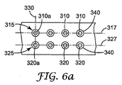
いくつかの実施形態において、第2の直線配列の第2のノズルのうちの実質的に全て(例えば、少なくとも80%、又は少なくとも90%、又は少なくとも95%、又は少なくとも99%)が、第1の直線配列の第1のノズルと対向する。図6aは、第1の共通の軸線317に沿って一直線に並んだ第1の成分の噴霧ノズル310の第1の直線配列315を示す。第2の直線配列325は、第2の共通の軸線327に沿って一直線に並んだ第2の成分の噴霧ノズル320で構成されている。第1及び第2の成分の噴霧ノズルの各々は、オリフィス340を貫いて突出している。
In some embodiments, substantially all (eg, at least 80%, or at least 90%, or at least 95%, or at least 99%) of the second nozzles of the second linear array are the first It faces the first nozzle of the linear array. FIG. 6 a shows a first
第1の共通の軸線317と第2の共通の軸線327は、実質的に平行である。各第2の成分の噴霧ノズル320は、第1の成分の噴霧ノズル310と対向している。第2の成分の噴霧ノズルのオリフィスの幾何学的中心を貫いて引かれ、且つ第2の共通の軸線と垂直である線が、第1の成分の噴霧ノズルのオリフィスと交差する場合、第2の成分の噴霧ノズルは、第1の成分の噴霧ノズルと対向する。例えば、線330が、第2の成分の噴霧ノズル320aのオリフィスの幾何学的中心を通過しており、且つ第2の共通の軸線327と垂直であるが、この線330が、第1の成分の噴霧ノズル310aのオリフィスと交差しているので、第2の成分の噴霧ノズル320aは、第1の成分の噴霧ノズル310aと対向している。
The first
いくつかの実施形態において、第2の成分の噴霧ノズルのうちの実質的に全て(例えば、少なくとも80%、又は少なくとも90%、又は少なくとも95%、又はさらに少なくとも99%)が、第1の成分の噴霧ノズルの全てから片寄ったものとなる。図6bは、第1の軸線417に沿って一直線に並んだ第1の成分の噴霧ノズル410の第1の直線配列415を示す。第2の直線配列425は、第2の共通の軸線427に沿って一直線に並んだ第2の成分の噴霧ノズル420で構成されている。第1の共通の軸線417及び第2の共通の軸線427は、実質的に平行である。各第2の成分の噴霧ノズル420は、第1の成分の噴霧ノズル410の各々から片寄っている。第2の成分の噴霧ノズルのオリフィスの幾何学的中心を貫いて引かれ、且つ第2の共通の軸線と垂直である線が、いずれの第1の成分の噴霧ノズルのオリフィスとも交差しない場合、第2の成分の噴霧ノズルは、第1の成分の噴霧ノズルから片寄っている。例えば、第2の線432が、第2の成分の噴霧ノズル420aのオリフィスの幾何学的中心を通過しており、第2の共通の軸線427と垂直であるが、この第2の線432が、第1の成分の噴霧ノズル410aのオリフィスとも、他のいずれの第1の成分の噴霧ノズルとも交差しないので、第2の成分の噴霧ノズル420aは、それに最も近い第1の成分の噴霧ノズル410a、並びに他の全ての第1の成分の噴霧ノズルから片寄っている。
In some embodiments, substantially all of the second component spray nozzles (eg, at least 80%, or at least 90%, or at least 95%, or even at least 99%) It will be offset from all of the spray nozzles. FIG. 6 b shows a first
図6bを参照すると、第1の線431が、第1の成分の噴霧ノズル410aの幾何学的中心を通過しており、且つ第2の共通の軸線427と垂直となっている。第2のノズル420aの、それに最も近い第1の成分の噴霧ノズル410aに対する片寄りの量は、第3の線433の長さとして定義され、この第3の線433は、第1の線431と第2の線432の双方と垂直である。一般に、円形オリフィスの場合、第2の成分の噴霧ノズル420aを片寄らせるためには、この長さは、第1の成分の噴霧ノズル410aの水力直径の2分の1を超えるものでなければならない。第2のノズルの実質的に全て(例えば、少なくとも約80%、又は90%又は95%又はさらに99%)の、それらに最も近い第1の成分の噴霧ノズルに対する片寄りは、いくつかの実施形態においては、第1の成分の噴霧ノズルの平均水力直径の少なくとも約1倍となり、いくつかの実施形態においては少なくとも約2倍、いくつかの実施形態においては少なくとも約3倍、更には少なくとも約5倍となる。いくつかの実施形態において、片寄りの量は、隣接する第2の成分の噴霧ノズル同士の間の距離の2分の1にほぼ等しくなる。
Referring to FIG. 6 b, the
いくつかの実施形態において、液体噴霧システムは、第3の成分の噴霧ノズルの第3の配列を有していてもよい。いくつかの実施形態において、第3の配列は直線配列となる。いくつかの実施形態において、第3の直線配列は、第1又は第2の直線配列と共に一直線に並ぶ。図5cを参照すると、いくつかの実施形態において、ノズルの第1及び第2の直線配列は、第1の共通の軸線240に沿って共に一直線に並んでおり、第1の成分の噴霧ノズル241は、第2の成分の噴霧ノズル242と交互に並んでいる。第3の成分の噴霧ノズル243は、第2の共通の軸線250に沿って一直線に並んでいる。いくつかの実施形態において、第1の共通の軸線240は、第2の共通の軸線250と実質的に平行である。いくつかの実施形態において、第3の成分の噴霧ノズルの各々は、第1の成分の噴霧ノズル又は第2の成分の噴霧ノズルと対向している。いくつかの実施形態において、第3の成分の噴霧ノズルの各々は、図5cに示すように、第1の成分の噴霧ノズルと第2の成分の噴霧ノズルの双方から片寄っている。
In some embodiments, the liquid spray system may have a third array of third component spray nozzles. In some embodiments, the third array is a linear array. In some embodiments, the third linear array is aligned with the first or second linear array. Referring to FIG. 5 c, in some embodiments, the first and second linear arrays of nozzles are aligned together along a first
本発明の一実施形態の例示的な多成分液体噴霧システムであって、平行に整列した、第1及び第2の成分の噴霧ノズルの直線配列を有するものを、図7a〜7cに示す。 An exemplary multi-component liquid spray system of one embodiment of the present invention having a linear array of first and second component spray nozzles aligned in parallel is shown in FIGS.
図7aを参照すると、ハウジング505を備える多成分液体噴霧システム500が示されている。ハウジング505は、端部パネル550及び555と、第1のダイ半部530と、第2のダイ半部540とを備えている。第1の成分の供給アセンブリ510が第1のダイ半部530に取り付けられており、第1の供給プレート511と、第1の二元プレート512と、第2の二元プレート513とを備えている。第1の供給プレート511は、少なくとも1つの第1の成分の供給ポート515を有している。同様に、第2の供給プレート521と、第1の二元プレート522と、第2の二元プレート523とを備える第2の成分の供給アセンブリ520が、第2のダイ半部540に取り付けられている。第2の供給プレート521は、少なくとも1つの第2の成分の供給ポート(図示せず)を有している。
Referring to FIG. 7a, a multi-component
端部パネル550が、第1及び第2のダイ半部に、例えばボルトによって取り付けられており、空気入口ポート551を有している。端部パネル555は、第1及び第2のダイ半部の反対側に取り付けられており、不図示の、空気の出口ポートを有している。
An
空気プレート560が、第1及び第2のダイ半部、並びに端部パネル550及び555のうちの1つ又は複数に取り付けられている。所望により、空気プレート560は、1つ以上のシム570によって、ダイ半部及び端部パネルから分離していてもよい。いくつかの実施形態において、シム570は、空気プレート560の底部と、空気プレート内の開口部を貫いて突出するノズルの先端部との距離を調整するために使用してもよい。
An
図7bを参照すると、第1のダイ半部530は、第1の液体のマニホールド531と、第1の空気のマニホールド532とを備えている。第1の液体のマニホールド531は開口部533を有しており、この開口部533により、第1の成分を含む第1の液体は、第1の液体のマニホールドから複数の第1の成分の噴霧ノズル内へと流れることができる。第1の空気のマニホールド532は開口部534を有しており、この開口部534により、空気は、第1の空気のマニホールド532から空気チャンバ内へと流れることができるが、その空気チャンバは、第1の空気の凹部535が第2のダイ半部内の対応する空気の凹部と合わせられたときに形成されるものである。開口部534は、2列の円形オリフィスとして示されている。他の開口部の形状(例えば、非円形オリフィス及びスロット)並びに配置(例えば、単一の列又は2列を超えるオリフィス)を使用してもよい。いくつかの実施形態において、第2のダイ半部の設計は、第1のダイ半部の設計と類似したものとなる。いくつかの実施形態において、液体のマニホールド、空気のマニホールド、及びそれらの対応する開口部の設計は、第1及び第2のダイ半部と異なっていても(different for)よい。相違は、液体の特性(例えば粘度、密度、及び反応度)、望ましい液体の流量範囲、並びに望ましい空気の流量における相違に適応するように設計されてもよい。
Referring to FIG. 7 b, the
例示的な第1の二元流動プレート612を図8aに示す。第1の二元流動プレート612は、第1及び第2のスルーポート622及び623を有する流動分布チャネル621を有している。一般に、第1の二元流動プレートは、供給プレート内の供給ポートを通過する液体が流動分布チャネルの中心近くに導かれるように、供給プレートに対して位置合わせされている。液体は次いで、チャネルに沿って第1及び第2のスルーポートに流れ、これらのポートを通り、第2の二元流動プレート(存在する場合)へと達する。いくつかの実施形態において、供給プレートは複数の供給ポートを有する。いくつかの実施形態において、第1の二元流動プレートは、単一の共通の流動分布チャネルを有し、その流動分布チャネルは、全ての供給ポートによって供給を受ける。いくつかの実施形態において、第1の二元流動プレートは複数の流動分布チャネルを有し、各チャネルは、供給ポートのうちの少なくとも1つによって供給を受ける。
An exemplary first
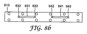
例示的な第2の二元流動プレート613を図8bに示す。第2の二元流動プレート613は、第1及び第2のスルーポート632及び633を有する第1の流動分布チャネル631と、第1及び第2のスルーポート642及び643を有する第2の流動分布チャネル641とを有する。いくつかの実施形態において、第2の二元流動プレートは、第1の二元流動プレート内のスルーポートの各々を通過した液体が、第2の二元流動プレート内の流動分布チャネルの中心近くに導かれるように、第1の二元流動プレートに対して位置合わせされている。流体は次いで、チャネルに沿って第2の二元流動プレートの第1及び第2のスルーポートに流れ、これらのポートを通り、更なる二元流動プレート(存在する場合)又は液体のマニホールドのいずれかに供給される。いくつかの実施形態において、第1の二元流動プレート内の複数のスルーホールは、第2の二元流動プレート内の共通の分布チャネルに供給を行う。一般に、存在する二元流動プレートの数は、慣例の設計考慮事項であり、例えば、ダイの長さ並びに液体の特性(例えば粘度及び密度)に依存し得るものである。
An exemplary second
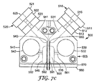
図7cを参照すると、第1のダイ半部530と第2のダイ半部540とを備える多成分液体噴霧システム500の端面図が示されている。一般に、第1の成分を含む第1の液体は、第1の入口ポート515の中を流れ、第1の二元プレート512及び第2の二元プレート513を通過し、第1の液体のマニホールド531内へと入る。第1の液体は次いで、開口部533を通過し、第1の成分の噴霧ノズル内591内へと入る。第1の成分の噴霧ノズル591は、第1の液体のマニホールドに直接的に又は間接的に連結されていてよい。いくつかの実施形態において、第1の成分の噴霧ノズル591は、開口部533に取り付けられている(例えば、圧入されるているか、ねじ込まれているか、又は接着されている)。第1の成分の噴霧ノズル591は、空気チャンバ595を通過し、所望による空気シム570及び空気プレート560内の開口部を貫いてハウジング505を抜け出している。
Referring to FIG. 7c, an end view of a multi-component
同様に、第2の成分を含む第2の液体は、第2の入口ポート525の中を流れ、第1の二元プレート522及び第2の二元プレート523を通過し、第2の液体のマニホールド541内へと入る。第2の液体は次いで、開口部543を通過し、第2の成分の噴霧ノズル内592へと入る。第2の成分の噴霧ノズル592は、第2の液体のマニホールドに直接的に又は間接的に連結されていてよい。いくつかの実施形態において、第2の成分の噴霧ノズル592は、開口部543に取り付けられている(例えば、圧入されるているか、ねじ込まれているか、又は接着されている)。第2の成分の噴霧ノズル592は、空気チャンバ595を通過し、所望による空気シム570及び空気プレート560内の開口部を貫いてハウジング505を抜け出している。
Similarly, the second liquid containing the second component flows through the
一般に、第1及び第2の空気のマニホールド内への空気の流量を調整することで、空気チャンバ内の圧力を制御することができる。図7cを参照すると、空気チャンバ595が、第1の空気の凹部535及び第2の空気の凹部545によって形成されている。第1の空気のマニホールド532は、空気通路561を介して空気チャンバ595と直接流体連通している。同様に、第2の空気のマニホールド542は、空気通路562を介して空気チャンバ595と直接流体連通している。いくつかの実施形態において、1つ以上の付加的な空気のマニホールドが、第1及び/又は第2の空気のマニホールドと空気チャンバとの間に位置していてもよい。付加的な空気のマニホールドは、空気チャンバ内の均一圧力を達成するのに有用となりうる。
In general, the pressure in the air chamber can be controlled by adjusting the flow rate of air into the first and second air manifolds. Referring to FIG. 7 c, an
いくつかの実施形態において、ハウジングは、空気チャンバを2つの部分に分割する部材を有していてもよい。第1の成分の噴霧ノズルは空気チャンバの第1の部分を通過し、第2の成分の噴霧ノズルは空気チャンバの第2の部分を通過することになる。そのような実施形態において、第1の部分における空気圧力は、例えば第1及び第2の空気のマニホールド内への空気の流量を制御することによって、第2の部分における空気圧力とは独立して調整することができる。 In some embodiments, the housing may have a member that divides the air chamber into two parts. The first component spray nozzle will pass through the first portion of the air chamber and the second component spray nozzle will pass through the second portion of the air chamber. In such an embodiment, the air pressure in the first portion is independent of the air pressure in the second portion, for example by controlling the flow of air into the first and second air manifolds. Can be adjusted.
空気プレート560を図9に示す。空気プレート560はノッチ566を有しており、これらのノッチ566は、ダイ半部及び端部プレート内の対応するタブを受け、空気プレートを位置合わせし拘束するのを補助する。例えば機械的な締結具及び接着剤を含めた他の方法を使用して、空気プレートをハウジングの残りに取り付けてもよい。空気プレート560はまた、第1のオリフィス564の第1の配列と、第2のオリフィス565の第2の配列とを有している。いくつかの実施形態において、オリフィスの第1の配列及び/又は第2の配列は直線配列である。いくつかの実施形態において、第1のオリフィスの第1の直線配列は、第2のオリフィスの第2の直線配列と実質的に平行である。一般に、第1の成分の噴霧ノズルのうちの少なくとも1つは、各第1のオリフィス564を通過し、第2の成分の噴霧ノズルのうちの少なくとも1つは、各第2のオリフィス565を通過する。いくつかの実施形態において、第1及び/又は第2のオリフィスのうちの1つ以上は、そのオリフィスを通過するノズルを有していなくてもよい。いくつかの実施形態において、第1及び/又は第2のオリフィスのうちの1つ以上は、そのオリフィスを通過する複数のノズルを有していてもよい。
An
図9に示すように、第2のオリフィス565の各々は、第1のオリフィス564と対向している。いくつかの実施形態において、第2のオリフィスのうちの1つ以上が、第1のオリフィスから片寄ったものとなる。いくつかの実施形態において、第2のオリフィスの実質的に全てが、第1のオリフィスから片寄ったものとなる。一般に、第1のオリフィスと第2のオリフィスが互いに対向している場合、それらのオリフィスを通過する、対応する第1の成分の噴霧ノズルと第2の成分の噴霧ノズルは、対向する。一般に、第1のオリフィスと第2のオリフィスが互いに片寄っている場合、それらのオリフィスを通過する、対応する第1の成分の噴霧ノズルと第2の成分の噴霧ノズルは、互いに片寄ったものとなる。
As shown in FIG. 9, each of the
いくつかの実施形態において、各第1の成分の噴霧ノズルのオリフィスは、その主流れの軸線と垂直となる。いくつかの実施形態において、各第2の成分の噴霧ノズルのオリフィスは、その主流れの軸線と垂直となる。いくつかの実施形態において、第1又は第2の成分の噴霧ノズルのうちの1つ以上が、斜角を付けられている。 In some embodiments, the orifice of each first component spray nozzle is perpendicular to its main flow axis. In some embodiments, the orifice of each second component spray nozzle is perpendicular to its main flow axis. In some embodiments, one or more of the first or second component spray nozzles are beveled.
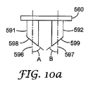
図10a〜10cを参照すると、空気プレート560を通過する第1の成分の噴霧ノズル591及び第2の成分の噴霧ノズル592が示されている。各第1の成分の噴霧ノズル591は、その主流れの軸線596に対して角度Aで斜角を付けられている。同様に、各第2の成分の噴霧ノズル592は、その主流れの軸線597に対して角度Bで斜角を付けられている。
Referring to FIGS. 10 a-10 c, a first
いくつかの実施形態において、第1の成分の噴霧ノズルの全ての斜角が実質的に同じとなる。いくつかの実施形態において、第1の成分の噴霧ノズルの斜角は、ノズル間で異なるものとなる。いくつかの実施形態において、第2の成分の噴霧ノズルの全ての斜角が実質的に同じとなる。いくつかの実施形態において、第2の成分の噴霧ノズルの斜角は、ノズル間で異なるものとなる。いくつかの実施形態において、第1の成分の噴霧ノズルの斜角は、第2の成分の噴霧ノズルの斜角と実質的に同じとなる。いくつかの実施形態において、第1の成分の噴霧ノズルの斜角は、第2の成分の噴霧ノズルの斜角と異なるものとなる。 In some embodiments, all bevel angles of the first component spray nozzles are substantially the same. In some embodiments, the bevel angle of the first component spray nozzles will vary from nozzle to nozzle. In some embodiments, all bevel angles of the second component spray nozzles are substantially the same. In some embodiments, the bevel angle of the second component spray nozzles will vary from nozzle to nozzle. In some embodiments, the bevel angle of the first component spray nozzle is substantially the same as the bevel angle of the second component spray nozzle. In some embodiments, the bevel angle of the first component spray nozzle is different from the bevel angle of the second component spray nozzle.
図10aを参照すると、第1の成分の噴霧ノズル591の斜面598が、第2の成分の噴霧ノズル592の斜面599と共に収束している。図10bを参照すると、第1の成分の噴霧ノズル591の斜面598が、第2の成分の噴霧ノズル592の斜面599から発散している。図10cを参照すると、第1の成分の噴霧ノズル591の斜面598が、第2の成分の噴霧ノズル592の斜面599と実質的に平行となっている。第1の成分の噴霧ノズルの斜面の、第2の成分の噴霧ノズルの斜面に対する他の配置もまた考えられる。一般に、第1の成分の噴霧ノズルの斜面は、同じ方向に配向されている。一般に、第2の成分の噴霧ノズルの全ての斜面は、同じ方向に配向されている。いくつかの実施形態において、斜面の配置は、ノズルの間で異なっていてもよい。
Referring to FIG. 10 a, the
一般に、本開示の多成分液体噴霧ダイは、2つ以上の成分をダイ出口の下流側で混合することが望ましい任意の用途において使用することができる。いくつかの実施形態において、第1の成分と第2の成分は、ダイ出口の下流側で混合される。いくつかの実施形態において、第1の成分を含む第1の液体は微粒化されて、第1の液体の大量の分散液滴を含んだ第1の噴霧を生成する。同様に、いくつかの実施形態において、第2の成分を含む第2の液体は微粒化されて、第2の液体の大量の分散液滴を含んだ第2の噴霧を生成する。いくつかの実施形態において、第1の噴霧の液滴のうちの少なくとも一部分は、ダイ出口から基材への飛翔において、第2の噴霧の液滴のうちの一部分と混合する。いくつかの実施形態において、第1の成分と第2の成分は、液滴が飛翔している間、相互作用、例えば反応する。 In general, the multi-component liquid spray die of the present disclosure can be used in any application where it is desirable to mix two or more components downstream of the die exit. In some embodiments, the first component and the second component are mixed downstream of the die exit. In some embodiments, a first liquid that includes a first component is atomized to produce a first spray that includes a large number of dispersed droplets of the first liquid. Similarly, in some embodiments, a second liquid that includes a second component is atomized to produce a second spray that includes a large number of dispersed droplets of the second liquid. In some embodiments, at least a portion of the first spray droplet mixes with a portion of the second spray droplet in flight from the die exit to the substrate. In some embodiments, the first component and the second component interact, for example, react while the droplet is flying.
一般に、第1及び第2の噴霧は基材に吹き付けられて、第1及び第2の液体を含んだ層を形成する。いくつかの実施形態において、第1及び第2の液体のうちの少なくとも一部分は、液体が基材に達するまで混合しない。 Generally, the first and second sprays are sprayed onto the substrate to form a layer containing the first and second liquids. In some embodiments, at least a portion of the first and second liquids do not mix until the liquid reaches the substrate.
いくつかの実施形態において、第1及び第2の液体の流量は、独立して調整することができる。いくつかの実施形態において、第1の成分と第2の成分との比を制御することが望ましい場合がある。一般に、目標の比は、特定の最終用途に依存し、いかなる値にもなり得る。例えば、いくつかの実施形態において、第1の成分と第2の成分は互いに反応する場合があり、目標の比は1となる場合がある。いくつかの実施形態において、第1の成分が第2の成分をわずかに上回ることが望ましい場合があり、その目標比は1よりも高く、例えば、1.01、1.1、1.5などとなることがある。いくつかの実施形態において、ある成分は触媒であってもよく、その成分の望ましい量は少なく、目標の比が0.5又はそれ未満、例えば0.1、0.05、又はさらに0.01未満となることがある。 In some embodiments, the flow rates of the first and second liquids can be adjusted independently. In some embodiments, it may be desirable to control the ratio of the first component to the second component. In general, the target ratio depends on the particular end use and can be any value. For example, in some embodiments, the first component and the second component may react with each other and the target ratio may be unity. In some embodiments, it may be desirable for the first component to be slightly above the second component, and the target ratio is higher than 1, for example, 1.01, 1.1, 1.5, etc. It may become. In some embodiments, a component may be a catalyst, the desired amount of that component being small, and a target ratio of 0.5 or less, such as 0.1, 0.05, or even 0.01. May be less.
いくつかの実施形態において、第1及び第2の成分は、非反応性であってもよく、例えば染料及び他の着色剤であってもよい。いくつかの実施形態において、第1の成分と第2の成分との比を変化させて、染料又は他の着色剤の混合物の、結果として生じる色を変化させることが望ましい場合がある。例えば、第1の成分が青色の染料であり、第2の成分が黄色の染料である場合、第1の成分(即ち青色の染料)の第2の成分(即ち黄色の染料)に対する比を変更することによって、種々の色合いの緑色を得ることができる。一般に、本開示のいくつかの実施形態の多成分噴霧ダイは、ダイの全長にわたって第1及び第2の成分の均一な比をもたらすために使用することができる。第1の成分と第2の成分との比は、いくつかの実施形態においては、ダイの長さ全体にわたって目標の比の10%以内であり、いくつかの実施形態においてはダイの長さ全体にわたって目標比の5%以内、いくつかの実施形態においては2%以内、またいくつかの実施形態においては1%以内又はそれ未満である。 In some embodiments, the first and second components may be non-reactive, such as dyes and other colorants. In some embodiments, it may be desirable to change the ratio of the first component to the second component to change the resulting color of the mixture of dyes or other colorants. For example, if the first component is a blue dye and the second component is a yellow dye, the ratio of the first component (ie blue dye) to the second component (ie yellow dye) is changed. By doing so, various shades of green can be obtained. In general, the multi-component spray die of some embodiments of the present disclosure can be used to provide a uniform ratio of the first and second components over the entire length of the die. The ratio of the first component to the second component is in some embodiments within 10% of the target ratio over the entire length of the die, and in some embodiments the entire length of the die. Over 5% of the target ratio, in some embodiments within 2%, and in some embodiments within 1% or less.
図11を参照すると、第1の成分を含む第1の液体610が、第1の成分の噴霧ノズル601の中を流れており、この第1の成分の噴霧ノズル601は、第1の成分の噴霧ノズルの第1の直線配列の一部である。同様に、第2の成分を含む第2の液体620が、第2の成分の噴霧ノズル602の中を流れており、この第2の成分の噴霧ノズル602は、第2の成分の噴霧ノズルの第2の直線配列の一部である。第1の成分の噴霧ノズル601は、斜面613内に置かれた出口オリフィス611を有している。第2の成分の噴霧ノズル602は、第1の成分の噴霧ノズル601と対向しており、斜面623内に置かれた出口オリフィス621を有している。第1及び第2の成分の噴霧ノズルは、それらの斜面が収束するように配向されている。
Referring to FIG. 11, a
第1の成分の噴霧ノズル601及び第2の成分の噴霧ノズル602は、空気プレート630内のオリフィス632を貫いて突出している。空気が、空気チャンバからオリフィス632を通じ、第1及び第2の成分の噴霧ノズルの突出長さに沿って流れている。第1及び第2の液体が、それぞれ、第1及び第2の成分の噴霧ノズルの出口オリフィスから吐出されるとき、この空気は、液体を微粒化して、噴霧、即ち多量の分散液滴を形成するのを支援する。いくつかの実施形態において、噴霧は出口オリフィスにおいて形成される。いくつかの実施形態において、液体は、出口オリフィスから液体柱として発射されてもよく、その液体柱は、ある距離だけ下流側で、多量の分散液滴へと形成される。いくつかの実施形態において、空気は、噴霧を生成するのに必要ではない。例えば、液体には、出口オリフィスから十分な圧力で排出された場合に微粒化するものもある。
The first
液滴641で構成された第1の液体の噴霧は、液滴642で構成された第2の液体の噴霧と混合する。第1の成分のうちの少なくとも一部分と第2の成分のうちの少なくとも一部分が、相互作用して(例えば混合し及び/又は反応して)液滴643を形成する。液滴641、642及び643は、基材640がノズルの下方で矢印650で示す方向に移動するとき、その基材640に吹き付けられる。いくつかの実施形態において、第1の成分と第2の成分との付加的な相互作用が基材640上で発生する。最終的に、基材640に吹き付けられる液体は合体して、相互作用した第1の成分と第2の成分の均一なフィルム645を形成する。
The first liquid spray composed of
いくつかの実施形態において、本発明のダイは、ウェブ又は物品に対する静止位置に装着することができる。ウェブ又は物品が移動して噴霧ダイを過ぎると、各成分が、実質的に均一な比で、ウェブ又は物品の全幅に至るまで又その全幅を含めて、ウェブ又は物品の望ましい幅全体にわたって塗布される。本発明の単一の固定ダイを使用して、均一な比の成分を、いくつかの実施形態においては5センチメートル(cm)を超え、いくつかの実施形態においては25cmを超え、またいくつかの実施形態においては60cmを超える幅全体にわたって塗布することができる。本発明の単一の固定ダイを使用して、均一な比の成分を、いくつかの実施形態においては、幅広のウェブ又は物品、即ち、90cm超、150cm超、又は更に300cm超の幅を有するウェブ又は物品に塗布することができる。 In some embodiments, the dies of the present invention can be mounted in a stationary position relative to the web or article. As the web or article moves past the spray die, each component is applied over the desired width of the web or article in a substantially uniform ratio, up to and including the entire width of the web or article. The Using a single fixed die of the present invention, a uniform ratio of components can be greater than 5 centimeters (cm) in some embodiments, greater than 25 cm in some embodiments, and some In this embodiment, it can be applied over the entire width exceeding 60 cm. Using a single fixed die of the present invention, a uniform ratio of components, in some embodiments, a wide web or article, i.e., greater than 90 cm, greater than 150 cm, or even greater than 300 cm. It can be applied to a web or article.
以下の具体的な、ただし非限定的な実施例は、本開示の一実施形態を説明するのに役立つものである。 The following specific but non-limiting examples serve to illustrate one embodiment of the present disclosure.
図7a、7cに示される、48cm(12インチ)の針の列幅を有するダイを使用して、VERSALINK P−1000ジアミンオリゴマー(ペンシルバニア州アレンタウン(Allentown)のエアープロダクツアンドケミカルズ社(Air Products and Chemicals Inc.))とPAPI 94イソシアネート(ミシガン州ミッドランド(Midland)のダウケミカルズUSA社(Dow Chemical USA))の配合物を4.25:1.00の重量比で混合し塗布した。
Using a die with a 48 cm (12 inch) needle row width as shown in FIGS. 7a, 7c, a VERSALINK P-1000 diamine oligomer (Air Products and Chemicals, Allentown, Pa.) Chemicals Inc.) and
2.92立方センチメートル/回転の計量ギヤポンプ(ノースカロライナ州サンフォード(Sanford)のパーカーハネフィン社(Parker Hannefin Corporation)のゼニスディビジョン(Zenith Division))に供給する加熱ホッパー内で、VERSALINK P−1000を93℃(200°F)まで加熱した。このギヤポンプを8.79rad/s(84回転/分)で動作させ、それによって約206.8KPa(30ポンド/平方インチ)の逆圧を発生させた。6.35mm(0.25インチ)の外径(O.D)と1.19mm(0.047インチ)の壁厚を有する首管を使用して、ギヤポンプをダイの一方の側部の入口に連結した。 2.92 cubic centimeters / rev metering gear pump (VERSALINK P-1000 at 93 ° C. in a heated hopper fed to the Zenith Division of Parker Hannefin Corporation of Sanford, NC) Heated to (200 ° F.). The gear pump was operated at 8.79 rad / s (84 rev / min), thereby producing a back pressure of about 30 6.8 kPa (30 pounds per square inch). Using a neck tube with an outer diameter (OD) of 6.35 mm (0.25 inch) and a wall thickness of 1.19 mm (0.047 inch), the gear pump is placed at the inlet on one side of the die. Connected.
PAPI 94は加熱されなかった。PAPI 94は、4.29rad/s(41回転毎/分)で動作する1.20立方センチメートル/回転の計量ギヤポンプ(パーカーハネフィン社(Parker Hannefin Corporation)のゼニスディビジョン(Zenith Division))を使用して、ダイの他方の側部に供給した。このギヤポンプとダイを、OD6.35mm×壁厚1.19mm(OD0.25インチ×壁厚0.047インチ)の首管を使用して連結した。
1.524mm(0.060インチ)の外径と0.762mm(0.030インチ)の内径を有する薄い管を、一方の端部で約45°の角度で斜角を付け、第1及び第2の成分の噴霧ノズルを形成した。第1の成分の噴霧ノズルを列内の中心において5.08mm(0.200インチ)だけ離間させて、第1の成分の噴霧ノズルの第1の直線配列を形成した。同様に、第2の成分の噴霧ノズルを列内の中心において5.08mm(0.200インチ)だけ離間させて、第2の成分の噴霧ノズルの第2の直線配列を形成した。第1の成分の噴霧ノズルの第1の直線配列を、中心において第2の成分の噴霧ノズルの第2の直線配列から5.08mm(0.200インチ)だけ離間させて、各第1の成分の噴霧ノズルが第2の成分の噴霧ノズルと対向するようにした。第1及び第2の成分の噴霧ノズルが、それらの斜面が収束するように配向された。 A thin tube having an outer diameter of 1.524 mm (0.060 inches) and an inner diameter of 0.762 mm (0.030 inches) is beveled at an angle of about 45 ° at one end, and the first and first A two component spray nozzle was formed. The first component spray nozzles were spaced 5.08 mm (0.200 inches) apart in the center of the row to form a first linear array of first component spray nozzles. Similarly, the second component spray nozzles were spaced 5.08 mm (0.200 inch) apart in the center of the row to form a second linear array of second component spray nozzles. A first linear array of first component spray nozzles is spaced 5.08 mm (0.200 inches) from the second linear array of second component spray nozzles in the center, with each first component The spray nozzle was made to face the spray nozzle of the second component. The spray nozzles of the first and second components were oriented so that their slopes converge.
圧縮空気を121℃(250°F)に加熱し、4つの空気分布マニホールドの入口に124KPa(18psi)で供給した。2つの成分がノズルの端部を抜け出すと、圧縮空気により、それらの成分は微粒化し、混合し、また、約63.5mm(2.5インチ)の距離でダイの下を通るウェブに吹き付けられた。目視検査の際、ウェブは均一にコーティングされており、また投入材料は十分に混合されていた。この組成物は、硬化すると、強靱でゴム様のコーティングをウェブ上に形成した。 The compressed air was heated to 121 ° C. (250 ° F.) and fed to the inlets of the four air distribution manifolds at 124 KPa (18 psi). As the two components exit the end of the nozzle, the compressed air causes the components to atomize, mix, and be sprayed onto the web passing under the die at a distance of approximately 63.5 mm (2.5 inches). It was. During visual inspection, the web was uniformly coated and the input material was well mixed. When cured, the composition formed a tough, rubber-like coating on the web.
本発明の様々な修正形態及び変更形態が、本発明の範疇及び趣旨から逸脱することなく、当業者には明らかとなるであろう。 Various modifications and alterations of this invention will become apparent to those skilled in the art without departing from the scope and spirit of this invention.
Claims (18)
第1の成分の噴霧ノズルの第1の配列であって、前記第1の成分の噴霧ノズルの各々は、前記部材内のオリフィスを貫いて突出している第1の配列と、
第2の成分の噴霧ノズルの第2の配列であって、前記第2の成分の噴霧ノズルの各々は、前記部材内のオリフィスを貫いて突出している第2の配列と、を備えており、
前記第1の成分の噴霧ノズルの各々は、前記第2の成分の噴霧ノズルのうちの少なくとも1つに隣接している、多成分液体噴霧システム。 An air chamber defined by a cavity in the housing and bounded on one side by a member comprising a plurality of orifices;
A first array of first component spray nozzles, each of the first component spray nozzles projecting through an orifice in the member; and
A second array of second component spray nozzles, each of the second component spray nozzles projecting through an orifice in the member; and
Each of the first component spray nozzles is adjacent to at least one of the second component spray nozzles.
第1の成分及び第2の成分を、請求項1の前記多成分液体噴霧システムに送達するステップと、
前記第1の成分を含む第1の噴霧を生成するために、前記第1の成分の噴霧ノズルの第1の配列を使用するステップと、
前記第2の成分を含む第2の噴霧を生成するために、前記第2の成分の噴霧ノズルの第2の配列を使用するステップと、
前記第1の噴霧の少なくとも第1の部分と第2の噴霧の少なくとも第2の部分とを混合させるステップと、を含む方法。 A method for producing a multi-component spray comprising:
Delivering a first component and a second component to the multi-component liquid spray system of claim 1;
Using a first array of spray nozzles of the first component to produce a first spray comprising the first component;
Using a second array of spray nozzles of the second component to produce a second spray comprising the second component;
Mixing at least a first portion of the first spray and at least a second portion of a second spray.
第1の成分及び第2の成分を、請求項1の前記多成分液体噴霧システムに送達するステップと、
前記第1の成分を含む第1の噴霧を生成するために、前記第1の成分の噴霧ノズルの第1の配列を使用するステップと、
前記第2の成分を含む第2の噴霧を生成するために、前記第2の成分の噴霧ノズルの第2の配列を使用するステップと、
前記第1及び第2の噴霧を物品に吹き付けるステップであって、少なくとも前記第1の噴霧の一部分と前記第2の噴霧の一部分は、前記物品に吹き付けられる前に混合されるステップと、を含む方法。 A method of making a coated article comprising:
Delivering a first component and a second component to the multi-component liquid spray system of claim 1;
Using a first array of spray nozzles of the first component to produce a first spray comprising the first component;
Using a second array of spray nozzles of the second component to produce a second spray comprising the second component;
Spraying the first and second sprays onto the article, wherein at least a portion of the first spray and a portion of the second spray are mixed prior to being sprayed onto the article. Method.
前記ハウジング内の前記空洞を形成するステップと、
前記空洞の境界を、複数のオリフィスを備える前記部材によって1つの側部において画すステップと、
前記第2の成分の噴霧ノズルの各々が前記部材内のオリフィスを貫いて突出するように、前記第2の成分の噴霧ノズルの第2の配列を配置するステップと、
前記第1の成分の噴霧ノズルの各々が前記部材内のオリフィスを貫いて突出し、且つ前記第2の成分の噴霧ノズルのうちの少なくとも1つに隣接するように、前記第1の成分の噴霧ノズルの第1の配列を配置するステップと、を含む方法。 A method of making the multi-component liquid spray system of claim 1 comprising:
Forming the cavity in the housing;
Demarcating the cavity boundary on one side by the member comprising a plurality of orifices;
Positioning the second array of second component spray nozzles such that each of the second component spray nozzles protrudes through an orifice in the member;
The first component spray nozzles such that each of the first component spray nozzles protrudes through an orifice in the member and is adjacent to at least one of the second component spray nozzles. Disposing the first array of methods.
前記ハウジングに結合された、第1の成分の第1の噴霧を生成するための手段と、
前記第1の噴霧を生成するための手段と流体連通した、前記第1の成分を送達するための手段と、
前記ハウジングに結合された、第2の成分の第2の噴霧を生成するための手段と、
前記第2の噴霧を生成するための手段と流体連通した、前記第2の成分を送達するための手段と、を備える多成分液体噴霧システム。 An air chamber defined by a cavity in the housing;
Means for generating a first spray of a first component coupled to the housing;
Means for delivering the first component in fluid communication with the means for generating the first spray;
Means for generating a second spray of a second component coupled to the housing;
A multi-component liquid spray system comprising: means for delivering the second component in fluid communication with the means for generating the second spray.
Applications Claiming Priority (2)
| Application Number | Priority Date | Filing Date | Title |
|---|---|---|---|
| US74823305P | 2005-12-01 | 2005-12-01 | |
| PCT/US2006/045047 WO2007064532A1 (en) | 2005-12-01 | 2006-11-21 | Multi-component liquid spray systems |
Publications (2)
| Publication Number | Publication Date |
|---|---|
| JP2009517213A true JP2009517213A (en) | 2009-04-30 |
| JP2009517213A5 JP2009517213A5 (en) | 2009-11-26 |
Family
ID=38092569
Family Applications (1)
| Application Number | Title | Priority Date | Filing Date |
|---|---|---|---|
| JP2008543348A Withdrawn JP2009517213A (en) | 2005-12-01 | 2006-11-21 | Multi-component liquid spray system |
Country Status (5)
| Country | Link |
|---|---|
| US (1) | US20070125888A1 (en) |
| EP (1) | EP1954399A4 (en) |
| JP (1) | JP2009517213A (en) |
| CN (1) | CN101309755A (en) |
| WO (1) | WO2007064532A1 (en) |
Cited By (2)
| Publication number | Priority date | Publication date | Assignee | Title |
|---|---|---|---|---|
| KR101672784B1 (en) * | 2016-04-15 | 2016-11-04 | 이종주 | Nozzle unit and coating apparatus using thereof |
| WO2023112542A1 (en) * | 2021-12-16 | 2023-06-22 | 東レ株式会社 | Slot-type spray nozzle, application apparatus, and film-coated material production method |
Families Citing this family (17)
| Publication number | Priority date | Publication date | Assignee | Title |
|---|---|---|---|---|
| US9186881B2 (en) * | 2009-03-09 | 2015-11-17 | Illinois Tool Works Inc. | Thermally isolated liquid supply for web moistening |
| EP2485851A4 (en) * | 2009-10-05 | 2014-04-30 | Nordson Corp | Two-component liquid dispenser gun and system |
| US10525489B2 (en) * | 2013-03-15 | 2020-01-07 | Honda Motor Co., Ltd. | Automated sprayer assembly |
| DE102016014944A1 (en) | 2016-12-14 | 2018-06-14 | Dürr Systems Ag | Coating method and corresponding coating device |
| DE102016014953A1 (en) | 2016-12-14 | 2018-06-14 | Dürr Systems Ag | Painting plant and corresponding painting process |
| DE102016014919A1 (en) * | 2016-12-14 | 2018-06-14 | Dürr Systems Ag | Application device and method for applying a coating agent |
| DE102016014956A1 (en) | 2016-12-14 | 2018-06-14 | Dürr Systems Ag | Coating device and associated operating method |
| DE102016014951A1 (en) | 2016-12-14 | 2018-06-14 | Dürr Systems Ag | Coating device and associated operating method |
| DE102016014946A1 (en) | 2016-12-14 | 2018-06-14 | Dürr Systems Ag | Printhead for applying a coating agent to a component |
| DE102016014947A1 (en) | 2016-12-14 | 2018-06-14 | Dürr Systems Ag | Printhead for applying a coating agent |
| DE102016014952A1 (en) | 2016-12-14 | 2018-06-14 | Dürr Systems Ag | Coating device for coating components |
| DE102016014943A1 (en) | 2016-12-14 | 2018-06-14 | Dürr Systems Ag | Printhead with tempering device |
| DE102016014955A1 (en) | 2016-12-14 | 2018-06-14 | Dürr Systems Ag | Coating device and corresponding coating method |
| DE102016014948A1 (en) | 2016-12-14 | 2018-06-14 | Dürr Systems Ag | Printhead and related operating procedures |
| KR102505266B1 (en) * | 2016-12-30 | 2023-02-28 | 어플라이드 머티어리얼스, 인코포레이티드 | Spray bar design for uniform liquid flow distribution on the substrate |
| CN109569964A (en) * | 2018-12-27 | 2019-04-05 | 北方民族大学 | A kind of spraying colloid system and method for multicomponent glue |
| CN111437897B (en) * | 2020-05-21 | 2023-10-20 | 浙江大学 | Double-flow type monodisperse droplet stream generation method and device |
Family Cites Families (28)
| Publication number | Priority date | Publication date | Assignee | Title |
|---|---|---|---|---|
| US3292868A (en) * | 1962-09-13 | 1966-12-20 | Aero Spray Inc | Spray nozzle |
| US3662960A (en) * | 1966-11-21 | 1972-05-16 | United Aircraft Corp | Injector head |
| US3788555A (en) * | 1970-04-27 | 1974-01-29 | Ransburg Electro Coating Corp | Apparatus for projecting plural component material upon a suitable base |
| US3827639A (en) * | 1972-01-04 | 1974-08-06 | J Relue | Drying chamber apparatus |
| US3825379A (en) * | 1972-04-10 | 1974-07-23 | Exxon Research Engineering Co | Melt-blowing die using capillary tubes |
| US3825380A (en) * | 1972-07-07 | 1974-07-23 | Exxon Research Engineering Co | Melt-blowing die for producing nonwoven mats |
| US3840179A (en) * | 1973-06-04 | 1974-10-08 | Binks Mfg Co | Spray apparatus |
| US3981650A (en) * | 1975-01-16 | 1976-09-21 | Beloit Corporation | Melt blowing intermixed filaments of two different polymers |
| US4187983A (en) * | 1977-10-17 | 1980-02-12 | National Cellulose Corporation | Plural component-multi state mixing and encapsulating nozzle |
| US4380570A (en) * | 1980-04-08 | 1983-04-19 | Schwarz Eckhard C A | Apparatus and process for melt-blowing a fiberforming thermoplastic polymer and product produced thereby |
| US4854504A (en) * | 1983-11-04 | 1989-08-08 | Graves Spray Supply Co., Inc. | Fiberglass spray nozzle |
| US4927079A (en) * | 1988-10-04 | 1990-05-22 | Binks Manufacturing Company | Plural component air spray gun and method |
| US5456596A (en) * | 1989-08-24 | 1995-10-10 | Energy Innovations, Inc. | Method and apparatus for producing multivortex fluid flow |
| US5145689A (en) * | 1990-10-17 | 1992-09-08 | Exxon Chemical Patents Inc. | Meltblowing die |
| US5115972A (en) * | 1991-02-06 | 1992-05-26 | Minnesota Mining And Manufacturing Company | Spray die for producing spray fans |
| DE4128590A1 (en) * | 1991-08-28 | 1993-03-04 | Kumag Ag | Multi-nozzle transfer of printing ink using pneumatic jets - electronically controlling timing of valve operations blowing ink out of individual nozzles of linear array |
| US5207658A (en) * | 1991-11-14 | 1993-05-04 | Rosen Howard J | Prick resistant medical needle for intravenous injections |
| CA2098784A1 (en) * | 1992-07-08 | 1994-01-09 | Bentley Boger | Apparatus and methods for applying conformal coatings to electronic circuit boards |
| DE69317706T2 (en) * | 1992-07-08 | 1998-07-30 | Nordson Corp | Apparatus and method for applying discontinuous coatings |
| US5549246A (en) * | 1992-10-26 | 1996-08-27 | Glas-Craft, Inc. | External mix application system and nozzle assembly |
| US5458291A (en) * | 1994-03-16 | 1995-10-17 | Nordson Corporation | Fluid applicator with a noncontacting die set |
| US5713519A (en) * | 1995-07-21 | 1998-02-03 | Minnesota Mining And Manufacturing Company | Fluid spraying system |
| US5902540A (en) * | 1996-10-08 | 1999-05-11 | Illinois Tool Works Inc. | Meltblowing method and apparatus |
| DE19722159A1 (en) * | 1997-05-27 | 1998-12-03 | Voith Sulzer Papiermasch Gmbh | Method and device for the direct or indirect application of a liquid or pasty application medium to a running surface |
| US6322003B1 (en) * | 1999-06-11 | 2001-11-27 | Spraying Systems Co. | Air assisted spray nozzle |
| US6776359B2 (en) * | 2001-11-06 | 2004-08-17 | Kolene Corporation | Spray nozzle configuration |
| FI111870B (en) * | 2002-01-15 | 2003-09-30 | Metso Paper Inc | Munstycksserie |
| US7059541B2 (en) * | 2004-01-15 | 2006-06-13 | Harris Research, Inc. | Fluid mixing block |
-
2006
- 2006-11-21 US US11/561,940 patent/US20070125888A1/en not_active Abandoned
- 2006-11-21 CN CNA2006800426050A patent/CN101309755A/en active Pending
- 2006-11-21 JP JP2008543348A patent/JP2009517213A/en not_active Withdrawn
- 2006-11-21 EP EP06838174A patent/EP1954399A4/en not_active Withdrawn
- 2006-11-21 WO PCT/US2006/045047 patent/WO2007064532A1/en active Application Filing
Cited By (2)
| Publication number | Priority date | Publication date | Assignee | Title |
|---|---|---|---|---|
| KR101672784B1 (en) * | 2016-04-15 | 2016-11-04 | 이종주 | Nozzle unit and coating apparatus using thereof |
| WO2023112542A1 (en) * | 2021-12-16 | 2023-06-22 | 東レ株式会社 | Slot-type spray nozzle, application apparatus, and film-coated material production method |
Also Published As
| Publication number | Publication date |
|---|---|
| CN101309755A (en) | 2008-11-19 |
| EP1954399A1 (en) | 2008-08-13 |
| EP1954399A4 (en) | 2008-11-26 |
| US20070125888A1 (en) | 2007-06-07 |
| WO2007064532A1 (en) | 2007-06-07 |
Similar Documents
| Publication | Publication Date | Title |
|---|---|---|
| JP2009517213A (en) | Multi-component liquid spray system | |
| US20070125877A1 (en) | Multi-component liquid spray systems | |
| US20070125886A1 (en) | Methods of spraying multi-component liquids | |
| CA2197891C (en) | Method and apparatus for producing closed cell foam | |
| CN101547744B (en) | Two fluid slit nozzle and method for manufacturing the same | |
| US5452856A (en) | Spray wand with spray fan control | |
| US6824071B1 (en) | Gel-coat application method and apparatus | |
| US20090115825A1 (en) | Droplet ejection device for a highly viscous liquid | |
| EP0498600B1 (en) | Spray die for producing spray fans | |
| US6695224B2 (en) | Spray nozzle for a two-component air-assisted, low pressure spray system | |
| US20040217202A1 (en) | Airless conformal coating apparatus and method | |
| US11224887B1 (en) | Adhesive dispensing system and method | |
| US6572031B2 (en) | Air-assisted, low pressure spray equipment having an improved spray nozzle | |
| US6672519B2 (en) | Air-assisted, low pressure spray equipment having an improved spray nozzle | |
| RU2152265C2 (en) | Orifice | |
| US6616068B2 (en) | Spray nozzle for two-component air-assisted, low pressure spray systems | |
| CN111823718B (en) | Coating apparatus for coating a coating product and method for cleaning such an apparatus | |
| JP2009233631A (en) | Mixing device of paint feeding device for multi-liquid coating | |
| US9844791B2 (en) | Micronozzle atomizers and methods of manufacture and use | |
| JP6944883B2 (en) | Nozzle for painting | |
| JP6871429B2 (en) | Painting equipment | |
| JP6951573B2 (en) | Nozzle for painting | |
| KR102412969B1 (en) | A fine spray nozzle with a simple structure and a disinfection device having the same | |
| JPH059147B2 (en) | ||
| EP2478964B1 (en) | Improved nozzle for spray guns intended for paints and derivatives, based on fluid transfer |
Legal Events
| Date | Code | Title | Description |
|---|---|---|---|
| A521 | Written amendment |
Free format text: JAPANESE INTERMEDIATE CODE: A523 Effective date: 20091001 |
|
| A621 | Written request for application examination |
Free format text: JAPANESE INTERMEDIATE CODE: A621 Effective date: 20091001 |
|
| A761 | Written withdrawal of application |
Free format text: JAPANESE INTERMEDIATE CODE: A761 Effective date: 20100621 |