JP2009511909A - System and method for angle resolved low coherence interferometry with endoscope - Google Patents
System and method for angle resolved low coherence interferometry with endoscope Download PDFInfo
- Publication number
- JP2009511909A JP2009511909A JP2008535655A JP2008535655A JP2009511909A JP 2009511909 A JP2009511909 A JP 2009511909A JP 2008535655 A JP2008535655 A JP 2008535655A JP 2008535655 A JP2008535655 A JP 2008535655A JP 2009511909 A JP2009511909 A JP 2009511909A
- Authority
- JP
- Japan
- Prior art keywords
- sample
- resolved
- angle
- reflected
- depth
- Prior art date
- Legal status (The legal status is an assumption and is not a legal conclusion. Google has not performed a legal analysis and makes no representation as to the accuracy of the status listed.)
- Pending
Links
- 238000000034 method Methods 0.000 title claims abstract description 62
- 238000005305 interferometry Methods 0.000 title description 6
- 230000003595 spectral effect Effects 0.000 claims abstract description 11
- 239000000835 fiber Substances 0.000 claims description 98
- 238000009826 distribution Methods 0.000 claims description 71
- 230000003287 optical effect Effects 0.000 claims description 23
- 238000003384 imaging method Methods 0.000 claims description 9
- 239000013307 optical fiber Substances 0.000 claims description 8
- 238000001228 spectrum Methods 0.000 claims description 7
- 230000005540 biological transmission Effects 0.000 claims description 4
- 230000001427 coherent effect Effects 0.000 claims description 4
- 238000012545 processing Methods 0.000 claims description 4
- 238000000354 decomposition reaction Methods 0.000 claims description 3
- 230000001131 transforming effect Effects 0.000 claims description 3
- 108091008695 photoreceptors Proteins 0.000 claims 4
- 230000002452 interceptive effect Effects 0.000 claims 2
- 238000001914 filtration Methods 0.000 claims 1
- 238000013480 data collection Methods 0.000 abstract description 14
- 239000000523 sample Substances 0.000 description 102
- 210000004027 cell Anatomy 0.000 description 14
- 238000005259 measurement Methods 0.000 description 11
- 210000001519 tissue Anatomy 0.000 description 11
- 239000004793 Polystyrene Substances 0.000 description 8
- 239000011324 bead Substances 0.000 description 8
- 229920002223 polystyrene Polymers 0.000 description 8
- 238000012360 testing method Methods 0.000 description 8
- 238000004458 analytical method Methods 0.000 description 7
- 238000000149 argon plasma sintering Methods 0.000 description 6
- 238000010586 diagram Methods 0.000 description 5
- 238000004364 calculation method Methods 0.000 description 3
- 230000008859 change Effects 0.000 description 3
- 238000001514 detection method Methods 0.000 description 3
- 238000003745 diagnosis Methods 0.000 description 3
- 238000005286 illumination Methods 0.000 description 3
- 238000002156 mixing Methods 0.000 description 3
- 208000005623 Carcinogenesis Diseases 0.000 description 2
- PEDCQBHIVMGVHV-UHFFFAOYSA-N Glycerine Chemical compound OCC(O)CO PEDCQBHIVMGVHV-UHFFFAOYSA-N 0.000 description 2
- 206010028980 Neoplasm Diseases 0.000 description 2
- 238000010171 animal model Methods 0.000 description 2
- 238000001574 biopsy Methods 0.000 description 2
- 230000036952 cancer formation Effects 0.000 description 2
- 231100000504 carcinogenesis Toxicity 0.000 description 2
- 230000001413 cellular effect Effects 0.000 description 2
- IDLFZVILOHSSID-OVLDLUHVSA-N corticotropin Chemical compound C([C@@H](C(=O)N[C@@H](CO)C(=O)N[C@@H](CCSC)C(=O)N[C@@H](CCC(O)=O)C(=O)N[C@@H](CC=1NC=NC=1)C(=O)N[C@@H](CC=1C=CC=CC=1)C(=O)N[C@@H](CCCNC(N)=N)C(=O)N[C@@H](CC=1C2=CC=CC=C2NC=1)C(=O)NCC(=O)N[C@@H](CCCCN)C(=O)N1[C@@H](CCC1)C(=O)N[C@@H](C(C)C)C(=O)NCC(=O)N[C@@H](CCCCN)C(=O)N[C@@H](CCCCN)C(=O)N[C@@H](CCCNC(N)=N)C(=O)N[C@@H](CCCNC(N)=N)C(=O)N1[C@@H](CCC1)C(=O)N[C@@H](C(C)C)C(=O)N[C@@H](CCCCN)C(=O)N[C@@H](C(C)C)C(=O)N[C@@H](CC=1C=CC(O)=CC=1)C(=O)N1[C@@H](CCC1)C(=O)N[C@@H](CC(N)=O)C(=O)NCC(=O)N[C@@H](C)C(=O)N[C@@H](CCC(O)=O)C(=O)N[C@@H](CC(O)=O)C(=O)N[C@@H](CCC(O)=O)C(=O)N[C@@H](CO)C(=O)N[C@@H](C)C(=O)N[C@@H](CCC(O)=O)C(=O)N[C@@H](C)C(=O)N[C@@H](CC=1C=CC=CC=1)C(=O)N1[C@@H](CCC1)C(=O)N[C@@H](CC(C)C)C(=O)N[C@@H](CCC(O)=O)C(=O)N[C@@H](CC=1C=CC=CC=1)C(O)=O)NC(=O)[C@@H](N)CO)C1=CC=C(O)C=C1 IDLFZVILOHSSID-OVLDLUHVSA-N 0.000 description 2
- 238000009792 diffusion process Methods 0.000 description 2
- 201000010099 disease Diseases 0.000 description 2
- 208000037265 diseases, disorders, signs and symptoms Diseases 0.000 description 2
- 238000005516 engineering process Methods 0.000 description 2
- 238000002474 experimental method Methods 0.000 description 2
- 239000011159 matrix material Substances 0.000 description 2
- 238000012986 modification Methods 0.000 description 2
- 230000004048 modification Effects 0.000 description 2
- 230000007935 neutral effect Effects 0.000 description 2
- 210000004940 nucleus Anatomy 0.000 description 2
- 238000012014 optical coherence tomography Methods 0.000 description 2
- 230000000737 periodic effect Effects 0.000 description 2
- 230000010287 polarization Effects 0.000 description 2
- 230000009467 reduction Effects 0.000 description 2
- 238000011160 research Methods 0.000 description 2
- 238000012216 screening Methods 0.000 description 2
- 239000000126 substance Substances 0.000 description 2
- 230000002123 temporal effect Effects 0.000 description 2
- 238000012935 Averaging Methods 0.000 description 1
- 101150110620 RR22 gene Proteins 0.000 description 1
- 230000002411 adverse Effects 0.000 description 1
- 239000002246 antineoplastic agent Substances 0.000 description 1
- 230000002238 attenuated effect Effects 0.000 description 1
- 210000003855 cell nucleus Anatomy 0.000 description 1
- 210000003850 cellular structure Anatomy 0.000 description 1
- 238000006243 chemical reaction Methods 0.000 description 1
- 238000001816 cooling Methods 0.000 description 1
- 230000002596 correlated effect Effects 0.000 description 1
- 238000005314 correlation function Methods 0.000 description 1
- 230000000875 corresponding effect Effects 0.000 description 1
- 238000007405 data analysis Methods 0.000 description 1
- 238000013461 design Methods 0.000 description 1
- 239000006185 dispersion Substances 0.000 description 1
- 230000000694 effects Effects 0.000 description 1
- 210000000981 epithelium Anatomy 0.000 description 1
- 238000011156 evaluation Methods 0.000 description 1
- 238000000605 extraction Methods 0.000 description 1
- 238000007429 general method Methods 0.000 description 1
- 239000011521 glass Substances 0.000 description 1
- 235000011187 glycerol Nutrition 0.000 description 1
- 230000036541 health Effects 0.000 description 1
- 230000009545 invasion Effects 0.000 description 1
- 230000033001 locomotion Effects 0.000 description 1
- 239000004005 microsphere Substances 0.000 description 1
- 239000000203 mixture Substances 0.000 description 1
- 238000012544 monitoring process Methods 0.000 description 1
- ORQBXQOJMQIAOY-UHFFFAOYSA-N nobelium Chemical compound [No] ORQBXQOJMQIAOY-UHFFFAOYSA-N 0.000 description 1
- 210000003463 organelle Anatomy 0.000 description 1
- 230000008520 organization Effects 0.000 description 1
- 230000010355 oscillation Effects 0.000 description 1
- 230000008569 process Effects 0.000 description 1
- 238000004611 spectroscopical analysis Methods 0.000 description 1
- 238000004544 sputter deposition Methods 0.000 description 1
- 230000001225 therapeutic effect Effects 0.000 description 1
- XLYOFNOQVPJJNP-UHFFFAOYSA-N water Substances O XLYOFNOQVPJJNP-UHFFFAOYSA-N 0.000 description 1
Images


Classifications
-
- G—PHYSICS
- G01—MEASURING; TESTING
- G01J—MEASUREMENT OF INTENSITY, VELOCITY, SPECTRAL CONTENT, POLARISATION, PHASE OR PULSE CHARACTERISTICS OF INFRARED, VISIBLE OR ULTRAVIOLET LIGHT; COLORIMETRY; RADIATION PYROMETRY
- G01J3/00—Spectrometry; Spectrophotometry; Monochromators; Measuring colours
- G01J3/28—Investigating the spectrum
- G01J3/44—Raman spectrometry; Scattering spectrometry ; Fluorescence spectrometry
- G01J3/4412—Scattering spectrometry
-
- A—HUMAN NECESSITIES
- A61—MEDICAL OR VETERINARY SCIENCE; HYGIENE
- A61B—DIAGNOSIS; SURGERY; IDENTIFICATION
- A61B5/00—Measuring for diagnostic purposes; Identification of persons
- A61B5/0059—Measuring for diagnostic purposes; Identification of persons using light, e.g. diagnosis by transillumination, diascopy, fluorescence
- A61B5/0075—Measuring for diagnostic purposes; Identification of persons using light, e.g. diagnosis by transillumination, diascopy, fluorescence by spectroscopy, i.e. measuring spectra, e.g. Raman spectroscopy, infrared absorption spectroscopy
-
- A—HUMAN NECESSITIES
- A61—MEDICAL OR VETERINARY SCIENCE; HYGIENE
- A61B—DIAGNOSIS; SURGERY; IDENTIFICATION
- A61B5/00—Measuring for diagnostic purposes; Identification of persons
- A61B5/72—Signal processing specially adapted for physiological signals or for diagnostic purposes
- A61B5/7235—Details of waveform analysis
- A61B5/7253—Details of waveform analysis characterised by using transforms
- A61B5/7257—Details of waveform analysis characterised by using transforms using Fourier transforms
-
- G—PHYSICS
- G01—MEASURING; TESTING
- G01B—MEASURING LENGTH, THICKNESS OR SIMILAR LINEAR DIMENSIONS; MEASURING ANGLES; MEASURING AREAS; MEASURING IRREGULARITIES OF SURFACES OR CONTOURS
- G01B9/00—Measuring instruments characterised by the use of optical techniques
- G01B9/02—Interferometers
- G01B9/02041—Interferometers characterised by particular imaging or detection techniques
- G01B9/02044—Imaging in the frequency domain, e.g. by using a spectrometer
-
- G—PHYSICS
- G01—MEASURING; TESTING
- G01B—MEASURING LENGTH, THICKNESS OR SIMILAR LINEAR DIMENSIONS; MEASURING ANGLES; MEASURING AREAS; MEASURING IRREGULARITIES OF SURFACES OR CONTOURS
- G01B9/00—Measuring instruments characterised by the use of optical techniques
- G01B9/02—Interferometers
- G01B9/02083—Interferometers characterised by particular signal processing and presentation
- G01B9/02084—Processing in the Fourier or frequency domain when not imaged in the frequency domain
-
- G—PHYSICS
- G01—MEASURING; TESTING
- G01B—MEASURING LENGTH, THICKNESS OR SIMILAR LINEAR DIMENSIONS; MEASURING ANGLES; MEASURING AREAS; MEASURING IRREGULARITIES OF SURFACES OR CONTOURS
- G01B9/00—Measuring instruments characterised by the use of optical techniques
- G01B9/02—Interferometers
- G01B9/02083—Interferometers characterised by particular signal processing and presentation
- G01B9/02087—Combining two or more images of the same region
-
- G—PHYSICS
- G01—MEASURING; TESTING
- G01B—MEASURING LENGTH, THICKNESS OR SIMILAR LINEAR DIMENSIONS; MEASURING ANGLES; MEASURING AREAS; MEASURING IRREGULARITIES OF SURFACES OR CONTOURS
- G01B9/00—Measuring instruments characterised by the use of optical techniques
- G01B9/02—Interferometers
- G01B9/0209—Low-coherence interferometers
-
- G—PHYSICS
- G01—MEASURING; TESTING
- G01J—MEASUREMENT OF INTENSITY, VELOCITY, SPECTRAL CONTENT, POLARISATION, PHASE OR PULSE CHARACTERISTICS OF INFRARED, VISIBLE OR ULTRAVIOLET LIGHT; COLORIMETRY; RADIATION PYROMETRY
- G01J3/00—Spectrometry; Spectrophotometry; Monochromators; Measuring colours
- G01J3/28—Investigating the spectrum
- G01J3/45—Interferometric spectrometry
- G01J3/453—Interferometric spectrometry by correlation of the amplitudes
- G01J3/4531—Devices without moving parts
-
- G—PHYSICS
- G01—MEASURING; TESTING
- G01N—INVESTIGATING OR ANALYSING MATERIALS BY DETERMINING THEIR CHEMICAL OR PHYSICAL PROPERTIES
- G01N21/00—Investigating or analysing materials by the use of optical means, i.e. using sub-millimetre waves, infrared, visible or ultraviolet light
- G01N21/17—Systems in which incident light is modified in accordance with the properties of the material investigated
- G01N21/25—Colour; Spectral properties, i.e. comparison of effect of material on the light at two or more different wavelengths or wavelength bands
- G01N21/31—Investigating relative effect of material at wavelengths characteristic of specific elements or molecules, e.g. atomic absorption spectrometry
-
- G—PHYSICS
- G01—MEASURING; TESTING
- G01N—INVESTIGATING OR ANALYSING MATERIALS BY DETERMINING THEIR CHEMICAL OR PHYSICAL PROPERTIES
- G01N21/00—Investigating or analysing materials by the use of optical means, i.e. using sub-millimetre waves, infrared, visible or ultraviolet light
- G01N21/17—Systems in which incident light is modified in accordance with the properties of the material investigated
- G01N21/47—Scattering, i.e. diffuse reflection
- G01N21/4795—Scattering, i.e. diffuse reflection spatially resolved investigating of object in scattering medium
-
- A—HUMAN NECESSITIES
- A61—MEDICAL OR VETERINARY SCIENCE; HYGIENE
- A61B—DIAGNOSIS; SURGERY; IDENTIFICATION
- A61B5/00—Measuring for diagnostic purposes; Identification of persons
- A61B5/0059—Measuring for diagnostic purposes; Identification of persons using light, e.g. diagnosis by transillumination, diascopy, fluorescence
- A61B5/0062—Arrangements for scanning
- A61B5/0066—Optical coherence imaging
-
- A—HUMAN NECESSITIES
- A61—MEDICAL OR VETERINARY SCIENCE; HYGIENE
- A61B—DIAGNOSIS; SURGERY; IDENTIFICATION
- A61B5/00—Measuring for diagnostic purposes; Identification of persons
- A61B5/0059—Measuring for diagnostic purposes; Identification of persons using light, e.g. diagnosis by transillumination, diascopy, fluorescence
- A61B5/0082—Measuring for diagnostic purposes; Identification of persons using light, e.g. diagnosis by transillumination, diascopy, fluorescence adapted for particular medical purposes
- A61B5/0084—Measuring for diagnostic purposes; Identification of persons using light, e.g. diagnosis by transillumination, diascopy, fluorescence adapted for particular medical purposes for introduction into the body, e.g. by catheters
-
- G—PHYSICS
- G01—MEASURING; TESTING
- G01N—INVESTIGATING OR ANALYSING MATERIALS BY DETERMINING THEIR CHEMICAL OR PHYSICAL PROPERTIES
- G01N21/00—Investigating or analysing materials by the use of optical means, i.e. using sub-millimetre waves, infrared, visible or ultraviolet light
- G01N21/17—Systems in which incident light is modified in accordance with the properties of the material investigated
- G01N21/47—Scattering, i.e. diffuse reflection
- G01N2021/4704—Angular selective
- G01N2021/4709—Backscatter
-
- G—PHYSICS
- G01—MEASURING; TESTING
- G01N—INVESTIGATING OR ANALYSING MATERIALS BY DETERMINING THEIR CHEMICAL OR PHYSICAL PROPERTIES
- G01N21/00—Investigating or analysing materials by the use of optical means, i.e. using sub-millimetre waves, infrared, visible or ultraviolet light
- G01N21/17—Systems in which incident light is modified in accordance with the properties of the material investigated
- G01N21/47—Scattering, i.e. diffuse reflection
- G01N2021/4735—Solid samples, e.g. paper, glass
-
- G—PHYSICS
- G01—MEASURING; TESTING
- G01N—INVESTIGATING OR ANALYSING MATERIALS BY DETERMINING THEIR CHEMICAL OR PHYSICAL PROPERTIES
- G01N2201/00—Features of devices classified in G01N21/00
- G01N2201/08—Optical fibres; light guides
Landscapes
- Physics & Mathematics (AREA)
- Spectroscopy & Molecular Physics (AREA)
- Health & Medical Sciences (AREA)
- Life Sciences & Earth Sciences (AREA)
- General Physics & Mathematics (AREA)
- Engineering & Computer Science (AREA)
- Pathology (AREA)
- Signal Processing (AREA)
- General Health & Medical Sciences (AREA)
- Biomedical Technology (AREA)
- Surgery (AREA)
- Biochemistry (AREA)
- Biophysics (AREA)
- Analytical Chemistry (AREA)
- Chemical & Material Sciences (AREA)
- Heart & Thoracic Surgery (AREA)
- Medical Informatics (AREA)
- Molecular Biology (AREA)
- Immunology (AREA)
- Animal Behavior & Ethology (AREA)
- Public Health (AREA)
- Veterinary Medicine (AREA)
- Mathematical Physics (AREA)
- Optics & Photonics (AREA)
- Artificial Intelligence (AREA)
- Computer Vision & Pattern Recognition (AREA)
- Physiology (AREA)
- Psychiatry (AREA)
- Investigating Or Analysing Materials By Optical Means (AREA)
Abstract
フーリエドメインa/LCI(faLCI)システムおよび方法は単一走査により高速度の生体データ収集を可能にする。角度分解および深さ分解スペクトル情報は1回走査で取得される。基準アームは、1回走査が必要とされるだけであるため、サンプルに対して固定状態を維持できる。基準信号および反射サンプル信号は相互相関を有し、サンプルから多数の反射角で散乱され、これにより並行して同時にサンプル上の多数の点からの反射を表す。サンプル上の多数の異なる点のそれぞれにおけるサンプルのすべての深さに関する情報は約40ミリ秒のオーダーの1回走査で取得できる。空間的、相互相関を有する基準信号から、構造(サイズ)情報はまた、散乱体のサイズ情報を角度分解データから取得できる技法を用いて取得できる。 Fourier domain a / LCI (faLCI) systems and methods allow high speed biometric data collection with a single scan. Angle-resolved and depth-resolved spectral information is acquired in a single scan. Since the reference arm only needs to be scanned once, it can remain stationary relative to the sample. The reference signal and the reflected sample signal are cross-correlated and are scattered from the sample at multiple reflection angles, thereby representing reflections from multiple points on the sample simultaneously in parallel. Information about the total depth of the sample at each of a number of different points on the sample can be obtained in a single scan on the order of about 40 milliseconds. From a reference signal with spatial and cross-correlation, structure (size) information can also be obtained using techniques that can obtain scatterer size information from angle-resolved data.
Description
本出願は、2005年10月11日出願の米国特許仮出願第60/725,603号の発明の名称「SYSTEMS AND METHODS FOR ENDOSCOPIC ANGLE−RESOLVED LOW COHERENCE INTERFEROMETRY」の優先権を主張する。この仮出願の全開示内容は、参照により本明細書に組み込まれる。 This application claims the priority of the invention entitled "SYSTEMS AND METHODS FOR ENDOCSOPIC ANGLE-RESOLVED LOW CHERENCE INTERFROMETRY" of US Provisional Application No. 60 / 725,603, filed Oct. 11, 2005. The entire disclosure of this provisional application is incorporated herein by reference.
本出願はまた米国特許出願第7,102,758号の発明の名称「FOURIER DOMAIN LOW−COHERENCE INTERFEROMETRY FOR LIGHT SCATTERING SPECTROSCOPY APPARATUS AND METHOD」に関する。この出願の全開示内容は、参照により本明細書に組み込まれる。 This application also relates to the title “FOURIER DOMAIN LOW-COHERENCE INTERFERE FORY FOR LIGHT SCATTERING SPECTOROSCOPY APPARATUS AND METHOD” of US Pat. No. 7,102,758. The entire disclosure of this application is incorporated herein by reference.
フーリエドメイン型角度分解低コヒーレンス干渉法(faLCI)システムおよび方法はサンプルの角度分解および深さ分解スペクトル情報のデータ収集を可能にし、このシステムでは、サンプルに関する深さおよびサイズ情報は、詳細には、生体への適用に対して高速度の単一走査により取得できる。 Fourier-domain angle-resolved low-coherence interferometry (faLCI) systems and methods allow data collection of sample angular-resolved and depth-resolved spectral information, in which depth and size information about the sample is It can be acquired by high-speed single scanning for living body applications.
細胞の構造特徴を試験することは、多くの臨床研究および実験研究に不可欠である。細胞研究のために試験において使用されるもっとも一般的なツールは顕微鏡である。顕微鏡試験は細胞および細胞構造の解明において大きな進歩をもたらしてきたが、顕微鏡試験は標本のアーティファクトにより本質的に制限される。細胞の特性は、化学薬品の添加のため変質する細胞の構造特徴を瞬間的に確認できるだけである。さらに、試験目的で細胞サンプルを取得するために、侵襲が必要である。 Testing the structural characteristics of cells is essential for many clinical and experimental studies. The most common tool used in testing for cell studies is the microscope. Although microscopic examination has made great progress in elucidating cells and cell structure, microscopic examination is inherently limited by specimen artifacts. The characteristics of the cells can only confirm the structural characteristics of the cells that change due to the addition of chemicals instantaneously. Furthermore, invasion is necessary to obtain cell samples for testing purposes.
このような理由から、光散乱分光法(LSS)が、細胞を含む生体試験への適用を可能にするために開発された。LSS方法は、細胞小器官の弾性散乱特性の変化を試験し、これらのサイズおよび他の寸法情報を推定する。組織および他の細胞構造体における細胞特徴を測定するためには、多重散乱されており、および散乱物体に関する容易に利用可能な情報を保有しない散乱光から、個々に散乱された光を区別することが必要である。この区別および弁別は、弱い散乱のサンプルに対する試験および分析を制限または限定することにより、あるいはモデリングを用いて拡散構成要素を除去することによって、偏光格子を利用するといったいくつかの方法で達成できる。 For this reason, light scattering spectroscopy (LSS) has been developed to enable application to biological tests involving cells. The LSS method examines changes in the elastic scattering properties of organelles and estimates their size and other dimensional information. To measure cellular characteristics in tissues and other cellular structures, distinguishing individually scattered light from scattered light that is multiply scattered and does not carry readily available information about the scattering object is required. This distinction and discrimination can be achieved in several ways, such as by utilizing a polarizing grating, by limiting or limiting testing and analysis on weakly scattered samples, or by removing the diffusing component using modeling.
表面下の部位からの個々の拡散光を選択的に検出する代替の方法として、低コヒーレンス干渉法(LCI)もまたLSSの1つの方法として探求されてきた。LCIは、例えば広帯域の白色光源といった、低い時間干渉性を有する光源を利用する。干渉は干渉計の経路長の遅延が光源の干渉時間と一致するときに実現するだけである。システムの距離分解能は光源の干渉長さにより決定され、通常組織のサンプルの試験に好適なマイクロメートル範囲にある。実験結果は、広帯域の光源およびその2次高調波を使用することにより、LCIを使用する弾性散乱に関する情報の復元を可能にすることが示されている。LCIは時間深さ走査を用いており、この走査では、サンプルを基準アームに対して移動させて光源をサンプル上に誘導し、サンプル上の特定点から散乱情報を受信する。その結果、サンプルを完全に走査するための走査時間は、約5から30分のオーダーであった。 As an alternative method of selectively detecting individual diffuse light from subsurface sites, low coherence interferometry (LCI) has also been explored as one method of LSS. LCI utilizes a light source with low temporal coherence, such as a broadband white light source. Interference is only realized when the delay of the interferometer path length matches the interference time of the light source. The distance resolution of the system is determined by the interference length of the light source and is usually in the micrometer range suitable for testing tissue samples. Experimental results have shown that by using a broadband light source and its second harmonic, it is possible to recover information about elastic scattering using LCI. LCI uses a time depth scan, in which the sample is moved relative to the reference arm to guide the light source onto the sample and receive scatter information from a specific point on the sample. As a result, the scan time for completely scanning the sample was on the order of about 5 to 30 minutes.
角度分解LCI(a/LCI)は細胞サイズに関する表面下の構造情報を取得する手段として開発されてきた。光は参照ビームとサンプルビームとに分割され、サンプルビームは散乱光の角度分布を試験するために様々な角度でサンプルに投射される。a/LCI方法は、表面下の部位からの個々の散乱光を検出するLCIの性能と、サブ波長の精度および正確度で構造情報を取得する光拡散方法の性能とを組み合わせることにより、深さ分解断層撮影画像を構成する。構造情報は、伝達角を備える基準場と混合される単一広帯域光源を使用して、後方散乱光の角度分布を試験することにより決定される。細胞のサイズ分布は、測定された角度分布の振動部分とMie理論の予測とを比較することにより決定される。このようなシステムは、「角度分解型低コヒーレンス干渉法を用いて測定される細胞組織および構造(Cellular Organization and Substructure Measured Using Angle−Resolved Low−Coherence Inteferometry)」(Biophysical Journal、82、2002年4月、2256−2265)に説明されており、この全内容は参照により本明細書に組み込まれる。 Angle-resolved LCI (a / LCI) has been developed as a means of obtaining subsurface structural information regarding cell size. The light is split into a reference beam and a sample beam, and the sample beam is projected onto the sample at various angles to test the angular distribution of scattered light. The a / LCI method combines the ability of LCI to detect individual scattered light from sites below the surface with the ability of a light diffusion method to obtain structural information with sub-wavelength accuracy and accuracy. A resolved tomographic image is constructed. Structural information is determined by examining the angular distribution of backscattered light using a single broadband light source mixed with a reference field with a transmission angle. The cell size distribution is determined by comparing the oscillating portion of the measured angular distribution with the prediction of Mie theory. Such a system is described in “Cellular Organization and Substructure Measurement Using Angle-Resolved Low-Coherence Interferometry” (Biophysical 4th month, 82). 2256-2265), the entire contents of which are incorporated herein by reference.
a/LCI方法は、細胞形態の測定および発がん現象の動物モデルにおける上皮内腫瘍の診断に適用されて好結果を得てきた。本出願の発明者は「改善された角度分解型低コヒーレンス干渉システムを用いる核形態の決定(Determining nuclear morphology using an improved angle−resolved low coherence interferometry system)」(Optics Express、2003年、11(25):3473−3484頁)においてこのようなシステムを開示しており、この全内容は、参照により本明細書に組み込まれる。サンプルに関する構造情報を取得するa/LCI方法は、組織および生体の細胞形態の測定、ならびに発がん現象の動物モデルにおける上皮内腫瘍の診断および化学抗がん剤の効能の評価に適用されて好結果を得てきた。a/LCIは組織処理することなく組織サンプルを予測的に選別するのに用いられ、生物医学診断として技術の可能性を実証してきた。 The a / LCI method has been successfully applied to the measurement of cell morphology and diagnosis of intraepithelial tumors in animal models of carcinogenesis. The inventor of the present application “Determining nuclear morphology using an improved angle-resolved low coherence interferometry system” (Op. 3; : Pages 3473-3484), the entire contents of which are hereby incorporated by reference. The a / LCI method for obtaining structural information about a sample has been successfully applied to the measurement of tissue and living cell morphology, as well as the diagnosis of intraepithelial tumors and the evaluation of the efficacy of chemical anticancer agents in animal models of carcinogenesis Have got. a / LCI has been used to predictively select tissue samples without tissue processing and has demonstrated the potential of the technology as a biomedical diagnosis.
初期の試作品および第2世代のa/LCIシステムは同様のデータを取得するのにそれぞれ30分および5分を必要としていた。時間領域深さに依存しているこれら従来のシステムは、従来のLCIベースのシステムで実現されているのと同様に走査する。検出される散乱角の逐次走査を達成するために、干渉計の基準アームの長さは機械的に調整されなければならなかった。角度特定性を得る方法は、干渉分析方式の参照ビームを可変角度で検出器平面と交差させることにより達成された。角度分解、深さ分解後方拡散分布を取得するこの一般的な方法は、米国特許第6,847,456号「Methods and systems using field−based light scattering spectroscopy」に開示されており、この全開示内容は、参照により本明細書に組み込まれる。 Early prototypes and second generation a / LCI systems required 30 and 5 minutes, respectively, to acquire similar data. These conventional systems that rely on time domain depth scan in the same way that they are implemented in conventional LCI-based systems. In order to achieve sequential scanning of the detected scattering angle, the length of the reference arm of the interferometer had to be adjusted mechanically. The method of obtaining angle specificity was achieved by crossing the reference beam of the interference analysis scheme with the detector plane at a variable angle. This general method for obtaining angle-resolved, depth-resolved back-diffusion distributions is disclosed in US Pat. No. 6,847,456 “Methods and systems using field-based light scattering sputtering spectroscopy”, the entire disclosure of which is incorporated herein by reference. Are incorporated herein by reference.
他の従来のLCIシステムは米国特許第6,002,480号および6,501,551号に開示されており、この全開示内容は、参照により本明細書に組み込まれる。米国特許第6,002,780号は、深さ分解分光分布を取得することを範囲に含み、弾性散乱特性による波長の変化を観測することにより散乱体のサイズを得ることを開示している。米国特許第6,501,551号は、干渉画像化の内視鏡応用を範囲に含み、フーリエドメイン概念を用いて深さ分解能を得ることを予測している。米国特許第6,501,551号は、角度分解散乱分布の測定、弾性散乱特性の分析により散乱体のサイズを決定するための散乱光の利用、およびそのデータが散乱または画像化データであるかどうかによらず、並行してデータを記録するための画像化分光計の使用、を述べていない。最後に、米国特許第7,061,622号は角度散乱分布を測定するための光ファイバ手段を開示しているが、フーリエドメイン概念を論じていない。また、画像化技術を説明するために、実施形態のすべては、試験される領域を制限する集束光学系を含む。 Other conventional LCI systems are disclosed in US Pat. Nos. 6,002,480 and 6,501,551, the entire disclosure of which is incorporated herein by reference. U.S. Pat. No. 6,002,780 covers obtaining a depth-resolved spectral distribution and discloses obtaining the size of the scatterer by observing changes in wavelength due to elastic scattering properties. US Pat. No. 6,501,551 covers the endoscopic application of interference imaging and predicts obtaining depth resolution using the Fourier domain concept. US Pat. No. 6,501,551 describes the use of scattered light to determine the size of a scatterer by measuring angle-resolved scatter distribution, analyzing the elastic scattering properties, and whether the data is scattered or imaged data. Regardless, it does not mention the use of an imaging spectrometer to record data in parallel. Finally, US Pat. No. 7,061,622 discloses an optical fiber means for measuring angular scatter distribution, but does not discuss the Fourier domain concept. Also, to illustrate the imaging technique, all of the embodiments include focusing optics that limit the area to be tested.
本発明はフーリエドメインa/LCI(faLCI)と称される新しいa/LCI方法を含み、この方法により、単一走査により高速のデータ収集を可能にし、生体への適用を十分可能にする。本発明は、サンプルに関する角度分解および深さ分解スペクトル情報を取得し、サンプルに関する深さおよびサイズ情報は単一走査により取得でき、また基準アームは、1回走査が必要とされるだけであるため、サンプルに対して固定状態を維持できる。基準信号および反射サンプル信号は相互相関を有し、サンプルから多数の反射角で散乱され、これにより並行して同時にサンプル上の多数の点からの反射を表す。 The present invention includes a new a / LCI method referred to as Fourier domain a / LCI (faLCI), which allows high-speed data collection with a single scan and is sufficiently applicable to living organisms. The present invention obtains angular and depth resolved spectral information about the sample, depth and size information about the sample can be obtained by a single scan, and the reference arm only needs to be scanned once. The fixed state can be maintained with respect to the sample. The reference signal and the reflected sample signal are cross-correlated and are scattered from the sample at multiple reflection angles, thereby representing reflections from multiple points on the sample simultaneously in parallel.
この角度分解、相互相関信号はスペクトル的に分散しているため、新しいデータ収集方式は重要である。この理由は、この新しいデータ収集方式により、データを1秒未満で取得でき、生体組織からデータを収集するのに必要とされる閾値を決定できるからである。サンプル上の多数の異なる点のそれぞれにおけるサンプルのすべての深さに関する情報は約40ミリ秒オーダーの1回走査により取得できる。空間的、相互相関を有する基準信号から、構造(サイズ)情報はまた、散乱体のサイズ情報を角度分析データから取得できる方法を用いて取得できる。 Since this angular resolution and cross-correlation signals are spectrally dispersed, a new data collection scheme is important. This is because with this new data collection scheme, data can be acquired in less than one second, and the threshold required to collect data from living tissue can be determined. Information about the total depth of the sample at each of a number of different points on the sample can be obtained by a single scan on the order of about 40 milliseconds. From a reference signal with spatial and cross-correlation, structure (size) information can also be obtained using a method that can obtain scatterer size information from angle analysis data.
本発明のfaLCI方法は、フーリエドメイン概念を用いて深さ分解情報を収集する。データ収集時間における信号対雑音および同一基準(commensurate)の低減はフーリエ(またはスペクトル)ドメインにおける深さ走査を記録することにより可能である。faLCIシステムはフーリエドメイン概念を画像分光器の使用と組み合わせることにより、角度分布を並行してスペクトル的に記録する。その後、本発明の深さ分解能は、サンプルに対するフーリエ変換平面における画像分光器の入口スリットを置くことにより得られる角度分解測定によって2つの混合場(field)のスペクトルをフーリエ変換することにより達成される。これは、スペクトル情報を深さ分解情報に、および角度情報を横方向空間分布に変換する。faLCIの性能は、最初は、深さ分解測定におけるポリスチレンビーズのサイズを抽出することにより実証された。 The faLCI method of the present invention collects depth resolution information using the Fourier domain concept. Reduction of signal-to-noise and the same reference in data acquisition time is possible by recording a depth scan in the Fourier (or spectral) domain. The faLCI system spectrally records the angular distribution in parallel by combining the Fourier domain concept with the use of an image spectrometer. Thereafter, the depth resolution of the present invention is achieved by Fourier transforming the spectra of the two field fields by angle-resolved measurements obtained by placing an image spectrometer entrance slit in the Fourier transform plane for the sample. . This converts spectral information into depth-resolved information and angular information into lateral spatial distribution. The performance of faLCI was first demonstrated by extracting the size of polystyrene beads in depth resolved measurements.
様々な数学的技術および方法が、角度分解、相互相関信号を利用してサンプルのサイズ情報を決定するために提供されている。 Various mathematical techniques and methods are provided for determining sample size information using angular resolution, cross-correlation signals.
本発明は特定のいずれの装置にも限定されない。1つの実施形態では、装置は改良されたマッハ−ツェンダー干渉計に基づいており、この装置では、スーパールミネッセントダイオードからの広帯域光はビームスプリッタによりサンプルに対して参照ビームおよび入力ビームに分割される。別の実施形態では、固有の光ファイバプローブを用いて光を送出し、所定のサンプルから散乱光の角度分布を収集できる。 The present invention is not limited to any particular device. In one embodiment, the apparatus is based on an improved Mach-Zehnder interferometer, in which broadband light from a superluminescent diode is split into a reference beam and an input beam with respect to the sample by a beam splitter. The In another embodiment, a unique fiber optic probe can be used to deliver light and collect the angular distribution of scattered light from a given sample.
a/LCI方法は、生検またはその後の組織病理学的評価を介する組織抽出の必要なく、組織の健康を評価するための臨床的に実行可能な方法である。a/LCIシステムは多数の目的、すなわち形成異常上皮組織の早期検出およびスクリーニング、疾病期間、治療行為の監視、および生検部位への臨床医の案内に適用できる。光学的a/LCIプローブの非侵襲性、非電離性特性は、悪影響を与えることなく繰返し適用できることを意味する。迅速な結果を提供するa/LCIの能力は疾病のスクリーニングに対する広範な適用性を大幅に強化する。 The a / LCI method is a clinically feasible method for assessing tissue health without the need for tissue extraction via biopsy or subsequent histopathological assessment. The a / LCI system can be applied for a number of purposes: early detection and screening of dysplastic epithelial tissue, disease duration, monitoring of therapeutic activity, and clinician guidance to the biopsy site. The non-invasive, non-ionizing properties of the optical a / LCI probe means that it can be applied repeatedly without adverse effects. The ability of a / LCI to provide rapid results greatly enhances its broad applicability for disease screening.
本明細書に記載され、および本明細書の一部を形成する添付図面は本発明のいくつかの態様を説明し、記述と併せて本発明の原理を説明するのに役立つ。 The accompanying drawings described herein and forming a part of this specification illustrate several aspects of the present invention and, together with the description, serve to explain the principles of the invention.
以下に記載される実施形態は、当業者が本発明を実現できるのに必要な情報を示しており、本発明を実現する最良様式を示す。添付図面と照合して以下の説明を読むことにより、当業者は本発明の概念を理解し、本明細書で詳細には説明されていないこれらの概念の適用を認識する。これらの概念および適用は本開示および添付の特許請求の範囲内であることは理解されるべきである。 The embodiments described below show the information necessary for those skilled in the art to realize the present invention and show the best mode for realizing the present invention. Upon reading the following description in conjunction with the accompanying drawings, those skilled in the art will understand the concepts of the invention and will recognize the application of these concepts not described in detail herein. It should be understood that these concepts and applications are within the scope of this disclosure and the appended claims.
本発明はフーリエドメインa/LCI(faLCI)と称される新しいa/LCI方法を含み、この方法により、単一走査により高速のデータ収集を可能にし、生体への適用を十分可能にする。本発明は、サンプルに関する角度分解および深さ分解スペクトル情報を取得し、サンプルに関する深さおよびサイズ情報は単一走査により取得でき、また基準アームは、1回走査が必要とされるだけであるため、サンプルに対して固定状態を維持できる。基準信号および反射サンプル信号は相互相関を有し、サンプルから多数の反射角で散乱され、これにより並行して同時にサンプル上の多数の点からの反射を表す。 The present invention includes a new a / LCI method referred to as Fourier domain a / LCI (faLCI), which allows high-speed data collection with a single scan and is sufficiently applicable to living organisms. The present invention obtains angular and depth resolved spectral information about the sample, depth and size information about the sample can be obtained by a single scan, and the reference arm only needs to be scanned once. The fixed state can be maintained with respect to the sample. The reference signal and the reflected sample signal are cross-correlated and are scattered from the sample at multiple reflection angles, thereby representing reflections from multiple points on the sample simultaneously in parallel.
この角度分解、相互相関信号はスペクトル的に分散しているため、新しいデータ収集方式は重要である。この理由は、この新しいデータ収集方式により、データを1秒未満で取得でき、生体組織からデータを収集するのに必要とされる閾値を決定できるからである。サンプル上の多数の異なる点のそれぞれにおけるサンプルのすべての深さに関する情報は約40ミリ秒オーダーの1回走査により取得できる。空間的、相互相関を有する基準信号から、構造(サイズ)情報はまた、散乱体のサイズ情報を角度分析データから取得できる方法を用いて取得できる。 Since this angular resolution and cross-correlation signals are spectrally dispersed, a new data collection scheme is important. This is because with this new data collection scheme, data can be acquired in less than one second, and the threshold required to collect data from living tissue can be determined. Information about the total depth of the sample at each of a number of different points on the sample can be obtained by a single scan on the order of about 40 milliseconds. From a reference signal with spatial and cross-correlation, structure (size) information can also be obtained using a method that can obtain scatterer size information from angle analysis data.
本発明のfaLCI方法は、フーリエドメイン概念を用いて深さ分解情報を収集する。データ収集時間における信号対雑音および同一基準の低減はフーリエ(またはスペクトル)ドメインにおける深さ走査を記録することにより可能である。faLCIシステムはフーリエドメイン概念を画像分光器の使用と組み合わせることにより、角度分布を並行してスペクトル的に記録する。その後、本発明の深さ分解能は、サンプルに対するフーリエ変換平面における画像分光器の入口スリットを置くことにより得られる角度分解測定によって2つの混合場のスペクトルをフーリエ変換することにより達成される。これは、スペクトル情報を深さ分解情報に、および角度情報を横方向空間分布に変換する。faLCIの性能は、最初は、深さ分解測定におけるポリスチレンビーズのサイズを抽出することにより実証された。 The faLCI method of the present invention collects depth resolution information using the Fourier domain concept. Reduction of signal-to-noise and same criteria in data acquisition time is possible by recording depth scans in the Fourier (or spectral) domain. The faLCI system spectrally records the angular distribution in parallel by combining the Fourier domain concept with the use of an image spectrometer. The depth resolution of the present invention is then achieved by Fourier transforming the two mixed-field spectra by angle-resolved measurements obtained by placing an image spectrometer entrance slit in the Fourier transform plane for the sample. This converts spectral information into depth-resolved information and angular information into lateral spatial distribution. The performance of faLCI was first demonstrated by extracting the size of polystyrene beads in depth resolved measurements.
本発明の主要な進歩は3つの構成要素、すなわち(1)新しい迅速なデータ収集方法、(2)ファイバプローブ設計、および(3)データ分析方式に分類される。したがって、本発明は理解を容易にするためにこの分類事項に従って説明される。 The major advances of the present invention are divided into three components: (1) a new rapid data collection method, (2) a fiber probe design, and (3) a data analysis scheme. Accordingly, the present invention will be described according to this classification for ease of understanding.
また図2には、例示的な装置ならびにサンプルから散乱される角度および深さ分解分布データを取得するプロセスに含まれるステップが示されている。本発明の1つの実施形態によるfaLCI方式は図1Aに示される改良されたマッハ−ツェンダー干渉計に基づいている。スーパールミネッセントダイオード(SLD)12からの広帯域光10はミラー13により方向変更され(図2のステップ60)、ビームスプリッタBS1 20により参照ビーム14とサンプル18への入力ビーム16と分割される(図3のステップ62)。SLD12の出力パワーは3ミリワットであってもよく、例えば、λo=850nm、Δλ=20nmFWHMの仕様を有し、組織内の細胞層から散乱を分離するのに十分な低コヒーレンス長さを提供する。参照ビーム14の経路長は逆反射体RR22を調節するにより設定されるが、測定中は固定された状態を維持する。参照ビーム14はレンズL1(24)およびL2(26)を用いて拡大され、照射光を生成する(図2のステップ64)。この照射光は均一な平行光であり、画像分光器29内の分光器スリット48に到達する。例えば、L1は焦点距離1.5センチメートルを有してもよく、L2 26は焦点距離15センチメートルを有してもよい。
Also shown in FIG. 2 are steps involved in an exemplary apparatus and process for obtaining angle and depth resolved distribution data scattered from the sample. The faLCI scheme according to one embodiment of the present invention is based on the improved Mach-Zehnder interferometer shown in FIG. 1A. The
レンズL3(31)およびL4(38)はサンプル18上に入射する平行ペンシルビーム30を生成するように配置される(図2のステップ66)。レンズL3(31)に対して垂直にレンズL4(38)を配置することにより、入力ビーム30は光軸に対して0.10ラジアンの角度でサンプルを照射するように生成される。この配置によりレンズL4(38)の全開口角を用いてサンプル18から散乱光40を収集できる。レンズL4(38)は焦点距離3.5センチメートルを有してもよい。
Lenses L3 (31) and L4 (38) are positioned to produce a
サンプル18により散乱された光40はレンズL4(32)により収集され、レンズL5(43)およびL6(44)から構成される4f画像化システムにより中継され、これにより、レンズL4(32)のフーリエ平面が分光器スリット48で位相および振幅を再生される(図2のステップ68)。散乱光40は、画像分光器29への入口スリット(要素48として図1Bに示されている)に位置する組み合わせ場46と、第2ビームスプリッタBS2 42における基準場14と混合される(図2のステップ70)。画像分光器29は例えばActon Research社により製造されるモデルSP2150iであってもよい。図1Bはスリット48の寸法に対する散乱角の分布を示している。混合場は高い分解能格子(例えば1200l/mm)で分散され、冷却されたCCD50(例えば、Princeton Instruments社により製造されている1340×400、20μm×20μmピクセル、仕様10:400)を使用して検出される(図2のステップ72)。
The light 40 scattered by the
検出信号46は、光が分光器29により分散されると、分光器スリット48上の垂直位置yおよび波長λの関数である。ピクセル(m、n)における検出信号は、信号40および参照場16(Es、Er)と以下の式のように関連付けることができる。
![]()
![]()
ここで、φは2つの場30、16の間の位相差であり、<...>は時間における集合平均を示す。干渉項は信号ビーム30および参照ビーム16の強度を独立に測定し、全体強度からこれらを減算することにより抽出される。
Where φ is the phase difference between the two
深さ分解情報を得るために、各散乱角における波長スペクトルは、波数(k=2π/λ)スペクトルに補間され、およびフーリエ変換されて、以下の式で表される各垂直ピクセルynに対する空間相互相関ΓSR(z)を与える。
![]()
![]()
参照場14は以下の式で表される。
![]()
![]()
ここで、k0(y0およびΔk(Δy))はガウス波動ベクトル(空間)分布の中心および幅を表し、Δlは選択された経路長の差である。散乱場40は以下の式で表される。
![]()
![]()
ここで、Sjは深さljに置かれたj番目の界面から生じる散乱の振幅分布を表す。散乱場40の角度分布は、関係y=f4θによってレンズL4のフーリエ画像平面における位置分布に変換される。CCD50のピクセルサイズ(例えば20μm)に対して、これは角度分解能(例えば、0.57ミリラジアン)および予測される角度範囲(例えば228ミリラジアン)が得られる。
Here, S j represents the amplitude distribution of the scattering generated from the j-th interface placed at the depth l j . The angular distribution of the
式(3)および(4)を式(2)に代入し、および参照場14(Δy>>スリットの高さ)の均一性に注目することにより、検出器29上のn番目の垂直位置における空間相互相関性が得られる。
![]()
![]()
単一界面に対してこの式の値を求めると以下のようになる。
![]()
![]()
ここでは、散乱振幅Sは光源12の帯域幅全体にわたって感知できるほど変化しないと仮定した。この表現は、散乱角に対応する各垂直ピクセルにおける散乱分布40の深さ分解プロファイルを得ることができることを示している。
Here, it was assumed that the scattering amplitude S does not change appreciably over the entire bandwidth of the
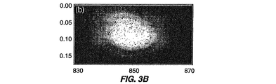
図3Aは、基準場16と、後方散乱方向に対して与えられる、波長および角度の関数として仮定した周波数ドメインにおける、ポリスチレンビーズのサンプルにより散乱された場40との和の全体の検出強度(上記の式(1))を表す典型的なデータを以下に示している。例示的な実施形態において、このデータは、40ミリ秒で収集され、予測範囲の約85%の186ミリラジアン全体にわたるデータを記録しており、高角度において信号の若干の損失を有する。
FIG. 3A shows the total detected intensity of the
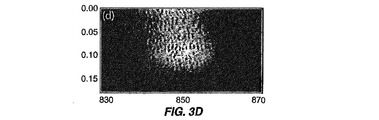
図3Bおよび図3Cはそれぞれ基準場および信号場14、30の強度を示している。全体の検出強度から、信号場および基準場14、30を減算すると、2つの場の間の干渉46は図3Dに示されるとおりに発生する。各角度において、干渉データ46はk空間に補間され、フーリエ変換されて、図4Aに示されるとおりサンプル18の角度深さ分解プロファイルを得る。角度分解相互相関信号46のフーリエ変換は、サンプル18からの多数の反射角度で散乱され、レンズL4(32)のフーリエ平面において得られた信号40の結果であって、角度および深さの関数としてサンプル18に関する深さ分解情報を生成する。これはサンプル18に関する深さ分解情報を提供する。角度分解、相互相関信号46はスペクトル的に分散しているため、データ収集においては1秒未満でデータを取得できる。サンプル18上の多数の異なる点(すなわち角度)のそれぞれにおいてサンプル18のすべての深さに関する情報は、約40ミリ秒オーダーで1回走査により取得できる。通常、時間ドメインベースの走査は多数の異なる点におけるサンプルのすべての深さに関する情報を取得するように要求され、その結果、長時間とサンプルに対する基準アームの運動を要求する。
3B and 3C show the intensities of the reference field and
図4Aに示されるサンプル18の深さ分解プロファイルを生成した実験では、サンプル18は、中立浮力を提供するために、水80%およびグリセリン20%(n=1.36)の混合物に懸濁するポリスチレン微小球(例えば、n=1.59、平均直径10.1μm、8.9%の分散、NIST(国立標準技術研究所)認定、Duke Scientific社)からなる。溶液は散乱長f=200μmを得るために調製される。サンプルはガラスカバースリップ(厚さd〜170μm)の後方の円形ウェル(直径8mm、深さ1mm)内に含まれる(図示せず)。サンプルビーム30はカバースリップを通してサンプル18上に入射する。カバースリップを通る往復厚み(第2=2(1.5)(170μm)=0.53mm、図4A参照)はこの方法の深さ分解性能を示している。データは1つの平均自由行程(MFP)全体を積分することにより集合平均される。空間平均により、低コヒーレンス光を使用する場合のスペックルを低減して、散乱サンプルを試験できる。フィッティング手順を容易にするために、散乱分布は、16μmを超える長さスケールにおける空間相関を抑圧するために選択されたカットオフ周波数を有するローパスフィルタされ、平滑な曲線を生成する。
In the experiment that produced the depth resolved profile of
サンプル18に関する深さ分解情報を取得することに加えて、開示されたデータ収集方式を用いてサンプル18から得られる散乱分布データ(すなわちa/LCIデータ)を用いて、Mie理論を用いて核のサイズを決定することもできる。サンプル18の散乱分布74はプロット線図(contour plot)として図4Bに示される。サンプル18に関する生の散乱情報74は信号場30および角度の関数として示される。フィルタ処理された曲線は散乱データ74を使用して決定される。フィルタ処理された散乱分布曲線76(すなわち散乱データ74の表示)とMie理論の予測との比較(図5Aの曲線78)により、サイズ分布を生成できる。
In addition to obtaining depth-resolved information about the
散乱データ76をMie理論に適合させるために、a/LCI信号を処理して核のサイズの特性である振動成分を抽出する。平滑化データ76は、低次多項式(例えばここでは4次が使用されるが、さらに最近の研究ではより低次の2次を使用する)に適合され、その後、背景傾向を除去するために分布76から減算される。結果として得られる振動成分は、次に、Mie理論78を用いて得られる理論上の予測値のデータベースと比較され、分析のために緩やかに変化する特徴が同様に除去される。 In order to fit the scattering data 76 to the Mie theory, the a / LCI signal is processed to extract the vibration component that is characteristic of the size of the nucleus. The smoothed data 76 is fitted to a low order polynomial (eg, a 4th order is used here, but more recent work uses a lower order 2nd order) and then distributed to remove background trends. Subtracted from 76. The resulting vibration component is then compared to a theoretical prediction database obtained using Mie theory 78, and slowly changing features are similarly removed for analysis.
フィルタ処理されたa/LCIデータ76とMie理論データ78との直接比較は、カイ2乗フィッティングアルゴリズムが固有振動でなくバックグラウンドスロープと一致する傾向があるため、不可能である。算出された理論的予測は、平均直径(d)および標準偏差(δD)により特徴付けられるサイズのガウス分布ならびに波長の分布を含み、広範な帯域幅光源を正確にモデル化する。 A direct comparison between the filtered a / LCI data 76 and the Mie theoretical data 78 is not possible because the chi-square fitting algorithm tends to match the background slope rather than the natural vibration. The calculated theoretical prediction includes a Gaussian distribution of size characterized by mean diameter (d) and standard deviation (δD) as well as a distribution of wavelengths, and accurately models a wide range of bandwidth light sources.
最良フィッティング(図5A)はデータ76とMie理論と間のカイ2乗を最小化することにより決定され(図5B)、10.2+/−1.7μmのサイズが得られ、真のサイズと優れた一致を示す。測定誤差は、おそらくは測定において記録される角度の制限範囲のために、ビーズの大きさの変化より大きい。 The best fitting (FIG. 5A) is determined by minimizing the chi-square between data 76 and Mie theory (FIG. 5B), resulting in a size of 10.2 +/− 1.7 μm, true size and superior Match. The measurement error is greater than the change in bead size, possibly due to the limited range of angles recorded in the measurement.
a/LCIデータの処理するおよびMie理論との比較の代替として、診断情報を得ることができるいくつか他の方法がある。これらは、フーリエ変換を用いて角度データを分析することにより、細胞核の周期的振動特性を識別することを含む。周期的振動は核のサイズと相関があり、したがって診断価値を有する。a/LCIデータを分析する別の方法は、データを有限要素法(FEM)またはT−マトリクス計算を用いて生成される角度散乱分布のデータベースと比較することである。このような計算は、Mie理論と同様な制限を受けないため、優れた分析を提供できる。例えば、FEMまたはT−マトリクス計算は非球形散乱体および含有物を有する散乱体をモデル化できるのに対して、Mie理論は同質球体だけしかモデル化できない。 As an alternative to processing a / LCI data and comparing it to Mie theory, there are several other ways in which diagnostic information can be obtained. These include identifying periodic vibration characteristics of cell nuclei by analyzing angular data using Fourier transforms. Periodic oscillations are correlated with the size of the nucleus and thus have diagnostic value. Another way to analyze a / LCI data is to compare the data to a database of angular scatter distributions generated using finite element methods (FEM) or T-matrix calculations. Such calculations are not subject to the same limitations as Mie theory and can provide excellent analysis. For example, FEM or T-matrix calculations can model non-spherical scatterers and scatterers with inclusions, whereas Mie theory can only model homogeneous spheres.
代替の実施形態として、本発明はまた、内視鏡用途に対してa/LCIシステムにおいて使用するために、対象のサンプルに光を送出および光を収集する光ファイバを使用することもできる。この代替の実施形態は図6に示されている。 As an alternative embodiment, the present invention may also use an optical fiber that delivers and collects light to a sample of interest for use in an a / LCI system for endoscopic applications. This alternative embodiment is shown in FIG.
この代替の実施形態における光ファイバa/LCI方式はレンズのフーリエ変換特性を利用する。この特性は、物体がレンズの前方焦点面に配置される場合、共役画像平面における画像はこの物体のフーリエ変換であることを示す。空間分布のフーリエ変換(物体または画像)は、mm当たりの周期についての画像情報内容の表示である、空間周波数分布により表される。弾性散乱光の光学画像においては、波長は固定された最初の値を維持し、空間周波数表示は単に、散乱光の角度分布の倍率変更バージョンである。 The optical fiber a / LCI scheme in this alternative embodiment utilizes the Fourier transform characteristics of the lens. This characteristic indicates that if the object is placed in the front focal plane of the lens, the image in the conjugate image plane is a Fourier transform of this object. The Fourier transform (object or image) of the spatial distribution is represented by the spatial frequency distribution, which is a display of the image information content for the period per mm. In an optical image of elastically scattered light, the wavelength remains at a fixed initial value and the spatial frequency display is simply a scaled version of the angular distribution of scattered light.
光ファイバa/LCI方式では、角度分布は、収集レンズを使用してサンプルの共役フーリエ変換平面にファイバ束の遠位端を配置することにより捕集される。この角度分布は次に、画像分光器の入口スリット上に4fシステムを使用して画像化される位置である、ファイバ束の遠心端に伝えられる。ビームスプリッタは、スリットに入る前に基準場と散乱場を重ね合わせるために使用され、この結果、低コヒーレンス干渉法はまた深さ分解測定値を得るためにも使用できる。 In the fiber optic a / LCI scheme, the angular distribution is collected by placing the distal end of the fiber bundle in the conjugate Fourier transform plane of the sample using a collection lens. This angular distribution is then transmitted to the distal end of the fiber bundle, where it is imaged using the 4f system on the entrance slit of the image spectrometer. The beam splitter is used to superimpose the reference and scattered fields before entering the slit, so that low coherence interferometry can also be used to obtain depth resolved measurements.
次に図6に戻ると、光ファイバfaLCIスキームが示されている。広帯域光源10’からの光12’は、ファイバスプリッタ(FS)80を用いて基準場14’と信号場16’とに分割される。スプリッタ比20:1は、1つの実施形態においては、組織から戻される光が一般にわずかな入射パワーであるため、信号アーム82を介してサンプル18’により大きいパワーを振り向けるように選択される。
Turning now to FIG. 6, an optical fiber faLCI scheme is shown. The light 12 ′ from the
基準ファイバ14’内の光はファイバF1から出て、基準アーム経路長の全体位置合わせを可能にするために、変換ステージ86上に取り付けられたレンズL1(84)により平行光に変換される。この経路長は作動中に走査されないが、位置合わせ中に変更されてもよい。平行ビーム88はファイバ束F3(90)の端部91に寸法的に等しくなる配置され、この結果、平行ビーム88は等しい強度でF3内のすべてのファイバを照射する。F3(90)の遠位先端から出る基準場14’はファイバF4(94)により伝えられる散乱場と重ね合わせるために、レンズL3(92)により平行光に変換される。代替の実施形態では、ファイバF1(14’)から出る光は平行光に変換され、その後レンズ系を用いて拡大されてブロードビームを生成する。
The light in the reference fiber 14 'exits the fiber F1 and is converted to parallel light by a lens L1 (84) mounted on the
散乱場は干渉ファイバ束を用いて検出される。散乱場は、レンズL2(98)を使用して対象のサンプル18’の方向に向けられる信号アーム82内で光を用いて生成される。自由空間システムにおけるのと同様に、レンズL2(98)は単一モードファイバF2の中心から横方向に移動され、これにより、光軸に対してある角度をなして移動する平行ビームを生成するようにされる。入射ビームがある傾斜角でサンプルを照射する事実は、鏡面反射から弾性散乱情報を分離するのに不可欠である。サンプル18’により散乱される光は、干渉性単一モードまたは多重モードファイバのアレイからなるファイバ束により収集される。ファイバの遠位先端は、散乱光の角度分布を画像化するためにレンズL2(98)から離れて1つの焦点距離を維持される。図6に示される実施形態では、サンプル18’は機械式取付台100を使用してレンズL2(98)の前方焦点平面に配置される。図7に示される内視鏡と互換性のあるプローブでは、サンプルは、透明シース(要素102)を使用してレンズL2(98)の前方焦点平面に配置される。
The scattered field is detected using an interference fiber bundle. A scattered field is generated with light in a
図6および図7Bに示されるとおり、ファイバプローブF4(94)の近位端105から出る散乱光104はレンズL4(104)により平行光に変換され、ビームスプリッタBS(108)を使用して基準場14’と重ね合わされる。2つの結合された場110はレンズL5(112)を使用して画像分光器29’のスリット(図7の要素48’)に再画像化される。レンズL5(112)の焦点距離はスリット48’を最適に満たすために変更されてもよい。結果として得られる光信号は、図1Aおよび図1Bの装置に対して上述されたとおり、スリット48’の垂直寸法全体にわたる各散乱角に関する情報を含む。
As shown in FIGS. 6 and 7B, the
上述のa/LCI光ファイバプローブは0.45ラジアン範囲(約30°)にわたる角度分布を収集し、一瞬の間に完全な深さ分解散乱分布110を収集すると予測される。
The a / LCI fiber probe described above collects an angular distribution over the 0.45 radians range (approximately 30 °) and is expected to collect a complete depth-resolved
光工学の点からは同一であるファイバプローブを生成するためのいくつかの可能な方式が存在する。1つの可能な実現形態は信号および基準アームの両方における単一モードファイバの線形アレイである。代替として、基準アーム96は、干渉性ファイバ束または線形ファイバアレイのいずれかからなる信号アーム82を備える個別の単一モードファイバから構成される。
There are several possible ways to create a fiber probe that is identical from an optical engineering point of view. One possible implementation is a linear array of single mode fibers in both the signal and reference arms. Alternatively, the
ファイバプローブの先端はまた、実質的に同等であるいくつかの実現形態を有する。これらは、レンズL2(98)の代わりにドラムレンズまたはボールレンズの使用を含む。側視型プローブは、レンズおよびミラーまたはプリズムの組み合わせを使用して、またはレンズ−ミラーの組み合わせと交換するために凸面鏡を使用して作製できる。最終的に、プローブ全体は、探求される範囲の周辺走査を可能にするために半径方向に回転するように作製される。 The tip of the fiber probe also has several implementations that are substantially equivalent. These include the use of drum lenses or ball lenses instead of lens L2 (98). Side-view probes can be made using a lens and mirror or prism combination, or using a convex mirror to replace a lens-mirror combination. Eventually, the entire probe is made to rotate radially to allow perimeter scanning of the sought area.
本発明のさらに別のデータ収集の実施形態は、図5Aに示されるとおり改良されたマッハ−ツェンダー干渉計に基づくfa/LCIシステムである。ファイバ結合型スーパールミネッセントダイオード(SLD)光源12’’(例えば、Superlum社、P0=15mW、λ0=841.5nm、Δλ=49.5nm、干渉長さ=6.3μm)からの出力10’’は90/10ファイバスプリッタFS(80’)(例えばAC Photonics社により製造されている)によりサンプルアーム送出ファイバ16’’および基準アーム送出ファイバ14’’に分割される。サンプルアーム送出ファイバ16’’は、例えば次のいずれか、すなわち(1)先端部で組み込まれた偏光制御を備える単一モードファイバ、または(2)偏光維持ファイバのいずれかからなる。サンプルプローブ113は、送出ファイバ16’’の端面がファイバ束116の面と平行で同一平面となるように、ファイバ束116の遠位端にフェルール114に沿って送出ファイバ16’’(NA≒0.12)を固定することにより組み立てられる。ボールレンズL1(115)(例えば、f1=2.2mm)はプローブ113の面から1つの焦点距離に配置され、ファイバ束116上に中心合わせされ、レンズL1(115)の光軸から送出ファイバ16’’を片寄らせる。また図8Bに示されているこの構成は、例えば0.25ラジアンの角度でサンプル18’’上に入射する0.5mmの直径(例えば2f1NA)を有する平行ビーム120(例えばP=9mW)を生成する。
Yet another data collection embodiment of the present invention is a fa / LCI system based on an improved Mach-Zehnder interferometer as shown in FIG. 5A. Output from a fiber-coupled superluminescent diode (SLD)
サンプルからの散乱光112はレンズL1(115)およびレンズL1(115)のフーリエ変換特性により収集され、散乱場122の角度分布は、レンズL1(115)のフーリエ画像平面に配置される多重モード干渉性ファイバ束116(例えば、Schott North America社、長さ=840mm、ピクセルサイズ=8.2μm、画素数=13.5K)の遠位面において、空間分布に変換される。ファイバ束y’上の垂直位置と散乱角θと間の関係はy’=f1θにより与えられる。図のとおり、3つの選択された散乱角における散乱光122の光経路は図8Bに示されている。全体として、角度分布は、図8Cの強調表示された領域により示されるとおり、ファイバ束116’’の垂直ストリップを交差して、例えば約130の個別ファイバによりサンプリングされる。例えば、送出ファイバ16’’およびファイバ束116を分離する0.2mmの厚いフェルール(dj)は、この例では、最小の理論的集束角(θmin,th=(d1/f1)を0.09ラジアンに制限する。最大の理論的集束角はd1およびd2により決定され、ファイバ束の直径は(θmax,th=(d1+d2)/f1)により0.50ラジアンになるように決定される。標準的な散乱サンプル122を使用する実験では、有効角度範囲はθmin=0.12ラジアンからθmax=0.45ラジアンを示す。d1は、例えば、遠位フェルール123内にチャネルを形成し、チャネル内に送出ファイバ16’’を配置することにより最小化できる。ファイバ束116は空間干渉性を有し、近位面で収集される角度散乱分布の再生成をもたらす。加えて、ファイバ束116内のすべてのファイバが干渉長さ以内に一致する経路長であるため、各角度における散乱光122により移動される光経路長は同一である。参照により全内容を本明細書に組み込まれる、T.Q.Xie、D.Mukai、S.G.Guo、M.BrennerおよびZ.P.Chenによる「光ファイバ束光干渉断層撮影(Fiber−optic−bundle−based optical coherence tomography)」(Optics Letters 30(14)、1803‐1805(2005))(以下「Xie」)に開示されているシステムは、時間ドメイン光干渉断層撮影システムにおける多重モード干渉ファイバ束を開示しており、個別のファイバに結合された光のモードは異なる経路長を移動することを実証している。本発明のここでの例では、高次モードは、関連データを臨床的に収集するのに要求される深さ(約100μm)をはるかに超えて、基本モードから3.75mmの片寄りがあることが実験的に決定された。加えて、サンプルアームパワーが基準アームパワーより大幅に小さいため、高次モードにおけるパワーはダイナミックレンジに大きな影響を与えなかった。最終的に、Xieに開示されたシステムは個別のファイバを通して順次にデータを収集するが、本発明のここでの例では、130のファイバを用いて、ある角度範囲全体わたって同時に並行して散乱光を収集し、結果的に高速データ収集が達成される。
The scattered light 112 from the sample is collected by the Fourier transform characteristics of the lens L1 (115) and the lens L1 (115), and the angular distribution of the
ファイバ束116の近位端124から出る角度分布はL2およびL3の4f画像化システム(f2=3.0cm、f3=20.0cm)により中継され、画像分光器29’’(例えば、Acton Research社、InSpectrum 150)の入力スリット48’’に達する。4f画像化システムの理論上の大きさはこの例では(f3/f2)6.67である。実験的に、この大きさはこの例ではM=7.0と測定されたが、おそらくは、ンズL2(126)に対するファイバ束116の近位面124の位置に起因する相違を有する。分光器スリット48’’上の垂直位置yとθと間の結果として得られる関係はy=Mf1(θ−θmin)である。基準アームの光経路長はサンプルアームの基本モードの経路長と一致する。基準ファイバ14’’を出る光127はレンズL4(128)により平行光に変換され(例えば、f=3.5cm、スポットサイズ=8.4mm)、サンプル光の位相面曲率と一致し、画像分光器29’’のスリット48’’全体わたる一様な照射を生成する。基準場130は中性濃度フィルタ132により減衰され、ビームスプリッタBS(134)において角度散乱分布と混合される。混合場136は高分解能格子(例えば1200ライン/mm)により分散され、例えば、840nmを中心とするスペクトル範囲99nmをカバーする、一体型冷却CCD(図示せず)(例えば、1024×252、24μm×24μmピクセル、0.1nm分解能)を使用して検出される。
The angular distribution emanating from the
検出された信号136、波長λおよびθの関数は以下の式のとおり信号および基準場(Es、Er)に関連付けできる。
![]()
![]()
ここで、φは2つの場の間の位相差であり、(mn)はCCD上のピクセルを表し、<...>は時間的平均を指す。I(λm、θn)はNational Instruments社ソフトウェアにより製造されたLab VIEW(登録商標)を使用してPCにアップロードされ、320msで処理されて散乱強度の深さおよび角度分解プロット線図を生成する。上述の深さおよびサイズ情報を取得するための角度分解散乱場の処理を利用して、および特に図1Aおよび図1Bのデータ収集装置を参照して、次に、図8の装置により生成される散乱混合場136を用いてサンプル18’’に関する角度分解、深さ分解情報を得ることが利用できる。
Where φ is the phase difference between the two fields, (mn) represents the pixel on the CCD, <. . . > Indicates a temporal average. I (λ m , θ n ) is uploaded to a PC using Lab VIEW® manufactured by National Instruments software and processed in 320 ms to generate depth and angle resolved plots of scattered intensity To do. Utilizing the angle-resolved scattered field processing to obtain the depth and size information described above, and in particular with reference to the data collection device of FIGS. 1A and 1B, it is then generated by the device of FIG. It is possible to use the
上述の実施形態は、当業者が本発明を実現できるのに必要な情報を示し、本発明を実現する最良モードを示している。添付図面に照らして後続の説明を読むことにより、当業者は本発明の概念を理解し、本明細書で特に対応していないこれらの概念の用途を認識する。これらの概念および用途は本開示の範囲内であることが理解されなければならない。 The above-described embodiment shows information necessary for those skilled in the art to realize the present invention, and shows the best mode for realizing the present invention. Upon reading the following description in light of the accompanying drawings, those skilled in the art will understand the concepts of the invention and will recognize uses of these concepts not specifically addressed herein. It should be understood that these concepts and applications are within the scope of this disclosure.
当業者であれば本発明の好ましい実施形態に対する改良形態および変更形態を認識する。このような改良形態および変更形態のすべては、本明細書に開示された概念および特許請求の範囲内であると見なされる。 Those skilled in the art will recognize improvements and modifications to the preferred embodiments of the present invention. All such improvements and modifications are considered within the scope of the concepts and claims disclosed herein.
Claims (58)
サンプルに対して固定されたスプリッタ上に光源ビームを放射し、スプリッタは光源ビームからの光を分割して参照ビームおよびサンプルビームとを生成することと、
サンプルビームをサンプルの方向にある角度で誘導することと、
サンプルビームがサンプルから並行して同時に多数の反射角で反射散乱する結果として、角度分解反射サンプルビームを受光し、角度分解反射サンプルビームは反射サンプルビームの角度散乱分布を含むことと、
角度分解反射サンプルビームと参照ビームとの相互相関を取ることにより、サンプルに関する角度分解相互相関信号を生成することと、
角度分解相互相関信号をスペクトル的に分散することにより、多数の反射角のそれぞれにおいてサンプルに関する深さ分解情報を有する単一の角度分解、スペクトル分解相互相関反射プロファイルを生成することと、
角度相互相関信号をフーリエ変換することにより、角度および深さの関数としてサンプルに関する深さ分解信号を生成することと、
を含む方法。 A method for determining a depth characteristic of a scatterer in a sample by obtaining a depth-resolved spectrum of the sample, comprising:
Emitting a light source beam onto a splitter fixed to the sample, the splitter splitting the light from the source beam to generate a reference beam and a sample beam;
Directing the sample beam at an angle in the direction of the sample;
Receiving the angle-resolved reflected sample beam as a result of the sample beam reflecting and scattering simultaneously at multiple reflection angles in parallel from the sample, the angle-resolved reflected sample beam including an angular scatter distribution of the reflected sample beam;
Generating an angle-resolved cross-correlation signal for the sample by cross-correlating the angle-resolved reflected sample beam and the reference beam;
Spectrally dispersing the angle-resolved cross-correlation signal to generate a single angle-resolved, spectrally-resolved cross-correlation reflection profile having depth-resolved information about the sample at each of a number of reflection angles;
Generating a depth-resolved signal for the sample as a function of angle and depth by Fourier transforming the angle cross-correlation signal;
Including methods.
角度分解反射サンプルビームおよび参照ビームの強度を別個に測定することにより干渉項を決定することと、
角度分解反射サンプルビームの全体強度から干渉項を減算することと、
を含む、請求項1に記載の方法。 The step of cross-correlating the angle-resolved reflected sample beam with the reference beam is
Determining an interference term by separately measuring the intensity of the angle-resolved reflected sample beam and the reference beam;
Subtracting the interference term from the total intensity of the angle-resolved reflected sample beam;
The method of claim 1 comprising:
サンプルに対して固定された受光体を備え、この受光体は、
同時に並行してサンプルから多数の反射角で反射散乱する角度分解反射サンプルビームを受光することにより、スプリッタにより光源ビームから分割されたサンプルビームの結果として生成される、角度および深さの関数としてサンプルに関する深さ分解情報をフーリエ変換を介して生成し、角度分解反射サンプルビームは角度分解反射サンプルビームの角度散乱分布を含み、
スプリッタにより光源ビームから分割された参照ビームを受光し、
角度分解反射サンプルビームと参照ビームとの相互相関を取ることにより、サンプルに関する角度分解および深さ分解相互相関信号を生成し、
装置はさらに、
角度分解および深さ分解相互相関信号をスペクトル的に分散することにより、多数の反射角のそれぞれにおいてサンプルに関する深さ分解情報を有する単一の角度分解、スペクトル分解相互相関反射プロファイルを生成する検出器と、
単一の角度分解、スペクトル分解相互相関反射プロファイルを受け取るプロセッサと、
を備える装置。 An apparatus for determining the size and depth characteristics of scatterers in a sample by obtaining a depth-resolved spectrum of the sample,
With a photoreceptor fixed to the sample,
The sample as a function of angle and depth, generated as a result of the sample beam split from the source beam by the splitter, by simultaneously receiving an angle-resolved reflected sample beam that is reflected and scattered from the sample at multiple reflection angles in parallel Depth-resolved information about the angle-resolved reflected sample beam is generated via a Fourier transform, and the angle-resolved reflected sample beam includes an angular scatter distribution of the angle-resolved reflected sample beam,
The reference beam split from the light source beam by the splitter is received,
Generate an angle-resolved and depth-resolved cross-correlation signal for the sample by cross-correlating the angle-resolved reflected sample beam with the reference beam
The device further
Detector that produces a single angle-resolved, spectrally-resolved cross-correlation reflection profile with depth-resolved information about the sample at each of a number of reflection angles by spectrally dispersing the angle-resolved and depth-resolved cross-correlation signals When,
A processor that receives a single angularly resolved, spectrally resolved cross-correlation reflection profile;
A device comprising:
サンプルビームを伝達する送出ファイバであり、サンプルビームは送出ファイバを通してサンプルまで誘導され、サンプルから多数の反射角で散乱されて、散乱サンプルビームを生成する送出ファイバと、
光学要素の他方の焦点に配置されるサンプルにより反射される散乱サンプルビームを受光するために、光学要素の一方の焦点に位置する複数のファイバから構成される光ファイバ束受光体であり、光ファイバ束受光体は光学要素のフーリエ変換特性を介して散乱サンプルビームの角度分布を受け取る光ファイバ束受光体と、
散乱サンプルビームをスペクトル分散することにより、同時に並行して多数の反射角のそれぞれにおいて角度分解、スペクトル分解反射プロファイルを生成する検出器と、
角度分解、スペクトル分解反射プロファイルを受け取り、分析するプロセッサと、
を備える装置。 An apparatus for determining the size and depth characteristics of scatterers in a sample by obtaining a depth-resolved spectrum of the sample,
A delivery fiber for transmitting a sample beam, wherein the sample beam is directed through the delivery fiber to the sample and scattered from the sample at multiple reflection angles to produce a scattered sample beam;
An optical fiber bundle receiver comprising a plurality of fibers located at one focal point of an optical element for receiving a scattered sample beam reflected by a sample disposed at the other focal point of the optical element; A bundle receiver that receives the angular distribution of the scattered sample beam via the Fourier transform characteristics of the optical element; and
A detector that produces an angularly resolved, spectrally resolved reflection profile at each of a number of reflection angles simultaneously in parallel by spectrally dispersing the scattered sample beam;
A processor that receives and analyzes angularly resolved, spectrally resolved reflection profiles;
A device comprising:
Applications Claiming Priority (2)
| Application Number | Priority Date | Filing Date | Title |
|---|---|---|---|
| US72560305P | 2005-10-11 | 2005-10-11 | |
| PCT/US2006/039771 WO2007044821A1 (en) | 2005-10-11 | 2006-10-11 | Systems and method for endoscopic angle-resolved low coherence interferometry |
Related Child Applications (1)
| Application Number | Title | Priority Date | Filing Date |
|---|---|---|---|
| JP2012106902A Division JP5555277B2 (en) | 2005-10-11 | 2012-05-08 | System and method for angle resolved low coherence interferometry with endoscope |
Publications (2)
| Publication Number | Publication Date |
|---|---|
| JP2009511909A true JP2009511909A (en) | 2009-03-19 |
| JP2009511909A5 JP2009511909A5 (en) | 2009-11-26 |
Family
ID=37714242
Family Applications (2)
| Application Number | Title | Priority Date | Filing Date |
|---|---|---|---|
| JP2008535655A Pending JP2009511909A (en) | 2005-10-11 | 2006-10-11 | System and method for angle resolved low coherence interferometry with endoscope |
| JP2012106902A Expired - Fee Related JP5555277B2 (en) | 2005-10-11 | 2012-05-08 | System and method for angle resolved low coherence interferometry with endoscope |
Family Applications After (1)
| Application Number | Title | Priority Date | Filing Date |
|---|---|---|---|
| JP2012106902A Expired - Fee Related JP5555277B2 (en) | 2005-10-11 | 2012-05-08 | System and method for angle resolved low coherence interferometry with endoscope |
Country Status (9)
| Country | Link |
|---|---|
| US (3) | US7595889B2 (en) |
| EP (3) | EP1934567B1 (en) |
| JP (2) | JP2009511909A (en) |
| CN (1) | CN101326428B (en) |
| AU (1) | AU2006302086B2 (en) |
| CA (3) | CA2967964A1 (en) |
| ES (2) | ES2402796T3 (en) |
| PT (2) | PT2444783E (en) |
| WO (1) | WO2007044821A1 (en) |
Cited By (4)
| Publication number | Priority date | Publication date | Assignee | Title |
|---|---|---|---|---|
| JP2009544367A (en) * | 2006-07-21 | 2009-12-17 | オンコスコープ・インコーポレーテツド | Protective probe tip for use with fiber optic probes, especially for endoscopic applications |
| JP2013518256A (en) * | 2010-01-22 | 2013-05-20 | デユーク・ユニバーシテイ | Multiple windowing scheme for spectroscopic coherence tomography (OCT) and Fourier domain low coherence interferometry |
| US9687157B2 (en) | 2005-10-11 | 2017-06-27 | Duke University | Systems and methods for endoscopic angle-resolved low coherence interferometry |
| US9823127B2 (en) | 2010-01-22 | 2017-11-21 | Duke University | Systems and methods for deep spectroscopic imaging of biological samples with use of an interferometer and spectrometer |
Families Citing this family (106)
| Publication number | Priority date | Publication date | Assignee | Title |
|---|---|---|---|---|
| DE60141090D1 (en) | 2000-10-30 | 2010-03-04 | Gen Hospital Corp | OPTICAL SYSTEMS FOR TISSUE ANALYSIS |
| US9295391B1 (en) | 2000-11-10 | 2016-03-29 | The General Hospital Corporation | Spectrally encoded miniature endoscopic imaging probe |
| DE10297689B4 (en) | 2001-05-01 | 2007-10-18 | The General Hospital Corp., Boston | Method and device for the determination of atherosclerotic coating by measurement of optical tissue properties |
| US7355716B2 (en) | 2002-01-24 | 2008-04-08 | The General Hospital Corporation | Apparatus and method for ranging and noise reduction of low coherence interferometry LCI and optical coherence tomography OCT signals by parallel detection of spectral bands |
| EP1611470B1 (en) | 2003-03-31 | 2015-10-14 | The General Hospital Corporation | Speckle reduction in optical coherence tomography by path length encoded angular compounding |
| US7102758B2 (en) | 2003-05-06 | 2006-09-05 | Duke University | Fourier domain low-coherence interferometry for light scattering spectroscopy apparatus and method |
| EP2290339A3 (en) | 2003-06-06 | 2012-11-28 | The General Hospital Corporation | Process and apparatus for a wavelength tuned light source |
| US7808699B2 (en) * | 2003-09-25 | 2010-10-05 | Leica Microsystems Cms Gmbh | Microscope lens for total internal reflection microscopy and microscope |
| EP2270448B1 (en) | 2003-10-27 | 2020-03-18 | The General Hospital Corporation | Method and apparatus for performing optical imaging using frequency-domain interferometry |
| EP1754016B1 (en) | 2004-05-29 | 2016-05-18 | The General Hospital Corporation | Process, system and software arrangement for a chromatic dispersion compensation using reflective layers in optical coherence tomography (oct) imaging |
| WO2006014392A1 (en) | 2004-07-02 | 2006-02-09 | The General Hospital Corporation | Endoscopic imaging probe comprising dual clad fibre |
| US8081316B2 (en) | 2004-08-06 | 2011-12-20 | The General Hospital Corporation | Process, system and software arrangement for determining at least one location in a sample using an optical coherence tomography |
| US8965487B2 (en) | 2004-08-24 | 2015-02-24 | The General Hospital Corporation | Process, system and software arrangement for measuring a mechanical strain and elastic properties of a sample |
| JP5324095B2 (en) | 2004-08-24 | 2013-10-23 | ザ ジェネラル ホスピタル コーポレイション | Method and apparatus for imaging blood vessel segments |
| KR101269455B1 (en) | 2004-09-10 | 2013-05-30 | 더 제너럴 하스피탈 코포레이션 | System and method for optical coherence imaging |
| EP2329759B1 (en) | 2004-09-29 | 2014-03-12 | The General Hospital Corporation | System and method for optical coherence imaging |
| EP2278265A3 (en) | 2004-11-24 | 2011-06-29 | The General Hospital Corporation | Common-Path Interferometer for Endoscopic OCT |
| JP2008521516A (en) | 2004-11-29 | 2008-06-26 | ザ ジェネラル ホスピタル コーポレイション | Configuration, apparatus, endoscope, catheter, and method for performing optical image generation by simultaneously illuminating and detecting multiple points on a sample |
| ES2432560T3 (en) * | 2005-03-10 | 2013-12-04 | Anatoly Babchenko | Optical sensor |
| EP2325803A1 (en) | 2005-04-28 | 2011-05-25 | The General Hospital Corporation | Evaluating optical coherence tomography information for an anatomical structure |
| US9060689B2 (en) | 2005-06-01 | 2015-06-23 | The General Hospital Corporation | Apparatus, method and system for performing phase-resolved optical frequency domain imaging |
| KR101387454B1 (en) | 2005-08-09 | 2014-04-22 | 더 제너럴 하스피탈 코포레이션 | Apparatus, methods and storage medium for performing polarization-based quadrature demodulation in optical coherence tomography |
| CN101304683B (en) | 2005-09-29 | 2012-12-12 | 通用医疗公司 | Method and apparatus for method for viewing and analyzing of one or more biological samples with progressively increasing resolutions |
| JP4642681B2 (en) * | 2005-09-30 | 2011-03-02 | 富士フイルム株式会社 | Optical tomographic imaging system |
| CA2967964A1 (en) * | 2005-10-11 | 2007-04-19 | Duke University | Systems and method for endoscopic angle-resolved low coherence interferometry |
| WO2007047690A1 (en) | 2005-10-14 | 2007-04-26 | The General Hospital Corporation | Spectral- and frequency- encoded fluorescence imaging |
| WO2007082228A1 (en) | 2006-01-10 | 2007-07-19 | The General Hospital Corporation | Systems and methods for generating data based on one or more spectrally-encoded endoscopy techniques |
| US8145018B2 (en) | 2006-01-19 | 2012-03-27 | The General Hospital Corporation | Apparatus for obtaining information for a structure using spectrally-encoded endoscopy techniques and methods for producing one or more optical arrangements |
| EP2289397A3 (en) | 2006-01-19 | 2011-04-06 | The General Hospital Corporation | Methods and systems for optical imaging of epithelial luminal organs by beam scanning thereof |
| US10426548B2 (en) | 2006-02-01 | 2019-10-01 | The General Hosppital Corporation | Methods and systems for providing electromagnetic radiation to at least one portion of a sample using conformal laser therapy procedures |
| WO2007149603A2 (en) | 2006-02-01 | 2007-12-27 | The General Hospital Corporation | Apparatus for applying a plurality of electro-magnetic radiations to a sample |
| WO2007092911A2 (en) | 2006-02-08 | 2007-08-16 | The General Hospital Corporation | Methods, arrangements and systems for obtaining information associated with an anatomical sample using optical microscopy |
| JP2009527770A (en) * | 2006-02-24 | 2009-07-30 | ザ ジェネラル ホスピタル コーポレイション | Method and system for performing angle-resolved Fourier domain optical coherence tomography |
| EP2517616A3 (en) | 2006-05-10 | 2013-03-06 | The General Hospital Corporation | Processes, arrangements and systems for providing frequency domain imaging of a sample |
| JP2010501877A (en) | 2006-08-25 | 2010-01-21 | ザ ジェネラル ホスピタル コーポレイション | Apparatus and method for improving optical coherence tomography imaging capabilities using volumetric filtering techniques |
| US8838213B2 (en) | 2006-10-19 | 2014-09-16 | The General Hospital Corporation | Apparatus and method for obtaining and providing imaging information associated with at least one portion of a sample, and effecting such portion(s) |
| US7949019B2 (en) | 2007-01-19 | 2011-05-24 | The General Hospital | Wavelength tuning source based on a rotatable reflector |
| US7502119B2 (en) * | 2007-01-29 | 2009-03-10 | Filmetrics, Inc. | Thin-film metrology using spectral reflectance with an intermediate in-line reference |
| EP2602651A3 (en) | 2007-03-23 | 2014-08-27 | The General Hospital Corporation | Methods, arrangements and apparatus for utilizing a wavelength-swept laser using angular scanning and dispersion procedures |
| WO2008121844A1 (en) | 2007-03-30 | 2008-10-09 | The General Hospital Corporation | System and method providing intracoronary laser speckle imaging for the detection of vulnerable plaque |
| US8045177B2 (en) | 2007-04-17 | 2011-10-25 | The General Hospital Corporation | Apparatus and methods for measuring vibrations using spectrally-encoded endoscopy |
| US8634082B2 (en) | 2007-06-20 | 2014-01-21 | The Trustess of Dartmouth College | Pulsed lasers in frequency domain diffuse optical tomography and spectroscopy |
| EP2173254A2 (en) | 2007-07-31 | 2010-04-14 | The General Hospital Corporation | Systems and methods for providing beam scan patterns for high speed doppler optical frequency domain imaging |
| US8040608B2 (en) | 2007-08-31 | 2011-10-18 | The General Hospital Corporation | System and method for self-interference fluorescence microscopy, and computer-accessible medium associated therewith |
| JP2009063407A (en) * | 2007-09-06 | 2009-03-26 | Yokogawa Electric Corp | Irradiation condenser |
| EP2188587A4 (en) * | 2007-09-13 | 2017-01-18 | Duke University | Apparatuses, systems, and methods for low-coherence interferometry (lci) |
| US7933021B2 (en) | 2007-10-30 | 2011-04-26 | The General Hospital Corporation | System and method for cladding mode detection |
| CA2711643A1 (en) * | 2008-01-08 | 2009-07-16 | Oncoscope, Inc. | Systems and methods for tissue examination, diagnostic, treatment, and/or monitoring |
| WO2009105537A2 (en) * | 2008-02-19 | 2009-08-27 | Trustees Of Tufts College | Non-invasive optical characterization of biomaterial mineralization |
| DE102008016973B4 (en) * | 2008-04-03 | 2009-12-31 | Precitec Optronik Gmbh | Interferometer and method for operating an interferometer |
| US7898656B2 (en) * | 2008-04-30 | 2011-03-01 | The General Hospital Corporation | Apparatus and method for cross axis parallel spectroscopy |
| JP5607610B2 (en) | 2008-05-07 | 2014-10-15 | ザ ジェネラル ホスピタル コーポレイション | Apparatus for determining structural features, method of operating apparatus and computer-accessible medium |
| US9013692B2 (en) * | 2008-06-12 | 2015-04-21 | East Carolina University | Flow cytometer apparatus for three dimensional difraction imaging and related methods |
| JP5795531B2 (en) | 2008-06-20 | 2015-10-14 | ザ ジェネラル ホスピタル コーポレイション | Fused fiber optic coupler structure and method of using the same |
| US9254089B2 (en) | 2008-07-14 | 2016-02-09 | The General Hospital Corporation | Apparatus and methods for facilitating at least partial overlap of dispersed ration on at least one sample |
| KR101109968B1 (en) * | 2008-07-23 | 2012-02-17 | 올림푸스 메디칼 시스템즈 가부시키가이샤 | Subject observation apparatus and subject observation method |
| US8634077B2 (en) | 2008-10-01 | 2014-01-21 | East Carolina University | Methods and systems for optically characterizing a turbid material using a structured incident beam |
| US8004688B2 (en) * | 2008-11-26 | 2011-08-23 | Zygo Corporation | Scan error correction in low coherence scanning interferometry |
| ES2957932T3 (en) | 2008-12-10 | 2024-01-30 | Massachusetts Gen Hospital | Systems, apparatus and procedures for extending the image depth range of optical coherence tomography using optical subsampling |
| WO2010083269A2 (en) * | 2009-01-17 | 2010-07-22 | Luna Innovations Incorporated | Optical imaging for optical device inspection |
| EP2389093A4 (en) | 2009-01-20 | 2013-07-31 | Gen Hospital Corp | Endoscopic biopsy apparatus, system and method |
| EP2382456A4 (en) | 2009-01-26 | 2012-07-25 | Gen Hospital Corp | System, method and computer-accessible medium for providing wide-field superresolution microscopy |
| WO2010105197A2 (en) | 2009-03-12 | 2010-09-16 | The General Hospital Corporation | Non-contact optical system, computer-accessible medium and method for measuring at least one mechanical property of tissue using coherent speckle techniques(s) |
| JP5325679B2 (en) * | 2009-07-03 | 2013-10-23 | 富士フイルム株式会社 | Dynamic light scattering measuring apparatus and light scattering intensity measuring method using low coherence light source |
| US11490826B2 (en) | 2009-07-14 | 2022-11-08 | The General Hospital Corporation | Apparatus, systems and methods for measuring flow and pressure within a vessel |
| TWI425188B (en) * | 2009-08-31 | 2014-02-01 | Zygo Corp | Microscope system and imaging interferometer system |
| JP5560628B2 (en) * | 2009-09-04 | 2014-07-30 | ソニー株式会社 | Inspection apparatus and inspection method |
| JP2011095181A (en) * | 2009-10-30 | 2011-05-12 | Sysmex Corp | Particle analyzer |
| DK2542154T3 (en) | 2010-03-05 | 2020-11-23 | Massachusetts Gen Hospital | APPARATUS FOR PROVIDING ELECTROMAGNETIC RADIATION TO A SAMPLE |
| JP2013522619A (en) * | 2010-03-19 | 2013-06-13 | デユーク・ユニバーシテイ | Single mode optical fiber based angle resolved low coherence interferometry (LCI) (a / LCI) and non-interference measurement system and method |
| US9069130B2 (en) | 2010-05-03 | 2015-06-30 | The General Hospital Corporation | Apparatus, method and system for generating optical radiation from biological gain media |
| US9557154B2 (en) | 2010-05-25 | 2017-01-31 | The General Hospital Corporation | Systems, devices, methods, apparatus and computer-accessible media for providing optical imaging of structures and compositions |
| JP5778762B2 (en) | 2010-05-25 | 2015-09-16 | ザ ジェネラル ホスピタル コーポレイション | Apparatus and method for spectral analysis of optical coherence tomography images |
| WO2011153434A2 (en) | 2010-06-03 | 2011-12-08 | The General Hospital Corporation | Apparatus and method for devices for imaging structures in or at one or more luminal organs |
| US8462349B1 (en) | 2010-07-20 | 2013-06-11 | Science Applications International Corporation | System and method for a self-referencing interferometer |
| JP5883018B2 (en) | 2010-10-27 | 2016-03-09 | ザ ジェネラル ホスピタル コーポレイション | Apparatus, system, and method for measuring blood pressure within at least one blood vessel |
| WO2013013049A1 (en) | 2011-07-19 | 2013-01-24 | The General Hospital Corporation | Systems, methods, apparatus and computer-accessible-medium for providing polarization-mode dispersion compensation in optical coherence tomography |
| EP3835718B1 (en) | 2011-08-25 | 2023-07-26 | The General Hospital Corporation | Apparatus for providing micro-optical coherence tomography inside a respiratory system |
| EP2565625A1 (en) * | 2011-09-05 | 2013-03-06 | Ludwig-Maximilians-Universität München | Optical measurement system and method for operating an optical measurement system |
| WO2013066631A1 (en) | 2011-10-18 | 2013-05-10 | The General Hospital Corporation | Apparatus and methods for producing and/or providing recirculating optical delay(s) |
| WO2013148306A1 (en) | 2012-03-30 | 2013-10-03 | The General Hospital Corporation | Imaging system, method and distal attachment for multidirectional field of view endoscopy |
| US11490797B2 (en) | 2012-05-21 | 2022-11-08 | The General Hospital Corporation | Apparatus, device and method for capsule microscopy |
| WO2014117130A1 (en) | 2013-01-28 | 2014-07-31 | The General Hospital Corporation | Apparatus and method for providing diffuse spectroscopy co-registered with optical frequency domain imaging |
| US10893806B2 (en) | 2013-01-29 | 2021-01-19 | The General Hospital Corporation | Apparatus, systems and methods for providing information regarding the aortic valve |
| WO2014121082A1 (en) | 2013-02-01 | 2014-08-07 | The General Hospital Corporation | Objective lens arrangement for confocal endomicroscopy |
| DE112014000814T5 (en) * | 2013-02-14 | 2015-10-29 | British Columbia Cancer Agency | Method and apparatus for optical measurements under ambient light conditions |
| JP6378311B2 (en) | 2013-03-15 | 2018-08-22 | ザ ジェネラル ホスピタル コーポレイション | Methods and systems for characterizing objects |
| WO2014144307A2 (en) | 2013-03-15 | 2014-09-18 | Gebhart Steven C | Probe assembly and disposable cover particularly for use in endoscope applications of low coherence interferometry |
| EP2997354A4 (en) | 2013-05-13 | 2017-01-18 | The General Hospital Corporation | Detecting self-interefering fluorescence phase and amplitude |
| EP3021735A4 (en) | 2013-07-19 | 2017-04-19 | The General Hospital Corporation | Determining eye motion by imaging retina. with feedback |
| EP3021734B1 (en) | 2013-07-19 | 2020-04-08 | The General Hospital Corporation | Imaging apparatus which utilizes multidirectional field of view endoscopy |
| WO2015013651A2 (en) | 2013-07-26 | 2015-01-29 | The General Hospital Corporation | System, apparatus and method utilizing optical dispersion for fourier-domain optical coherence tomography |
| WO2015105870A1 (en) | 2014-01-08 | 2015-07-16 | The General Hospital Corporation | Method and apparatus for microscopic imaging |
| WO2015116986A2 (en) | 2014-01-31 | 2015-08-06 | The General Hospital Corporation | System and method for facilitating manual and/or automatic volumetric imaging with real-time tension or force feedback using a tethered imaging device |
| WO2015153982A1 (en) | 2014-04-04 | 2015-10-08 | The General Hospital Corporation | Apparatus and method for controlling propagation and/or transmission of electromagnetic radiation in flexible waveguide(s) |
| CN106255874B (en) * | 2014-04-25 | 2018-09-21 | 爱色丽有限公司 | Sighting system |
| JP2017525435A (en) | 2014-07-25 | 2017-09-07 | ザ ジェネラル ホスピタル コーポレイション | Apparatus, devices and methods for in vivo imaging and diagnosis |
| US20170219485A1 (en) * | 2014-10-01 | 2017-08-03 | Purdue Research Foundation | Organism Identification |
| EP3268710A4 (en) * | 2015-03-12 | 2018-11-07 | Purdue Research Foundation | Biodynamic microscopes and methods of use thereof |
| DE102016218290A1 (en) * | 2016-07-15 | 2018-01-18 | Carl Zeiss Meditec Ag | Method for the highly sensitive measurement of distances and angles in the human eye |
| US10434970B2 (en) * | 2016-12-08 | 2019-10-08 | Toyota Jidosha Kabushiki Kaisha | Vehicle side section structure |
| GB201803523D0 (en) * | 2018-03-05 | 2018-04-18 | Malvern Panalytical Ltd | Improved particle sizing by optical diffraction |
| CN109620134B (en) * | 2019-01-21 | 2020-05-22 | 浙江大学 | Micro-angiography method and system based on optical fiber array multi-channel parallel detection |
| JP7149532B2 (en) * | 2019-04-26 | 2022-10-07 | 株式会社日立製作所 | Particle beam experiment data analyzer |
| US11333487B2 (en) | 2019-10-28 | 2022-05-17 | Kla Corporation | Common path mode fiber tip diffraction interferometer for wavefront measurement |
| CN113091896B (en) * | 2021-03-18 | 2023-03-14 | 西北工业大学 | Method and light path for dynamically measuring complete information of any light field based on polarization grating |
Citations (4)
| Publication number | Priority date | Publication date | Assignee | Title |
|---|---|---|---|---|
| JPS61110033A (en) * | 1984-11-02 | 1986-05-28 | Toray Ind Inc | Measuring apparatus for agglutination reaction |
| JPS61210910A (en) * | 1985-02-08 | 1986-09-19 | ザ・ボード・オブ・トラステイーズ・オブ・ザ・レランド・スタンフオード・ジユニア・ユニバーシテイ | Device for remotely sensing effect of peripheral environmenton pair of sensor |
| JPH0695036A (en) * | 1992-07-27 | 1994-04-08 | Nikon Corp | Optical element |
| JP2003532112A (en) * | 2000-04-28 | 2003-10-28 | マサチユセツツ・インスチチユート・オブ・テクノロジイ | Method and system using electric field based light scattering spectroscopy |
Family Cites Families (57)
| Publication number | Priority date | Publication date | Assignee | Title |
|---|---|---|---|---|
| US4646722A (en) | 1984-12-10 | 1987-03-03 | Opielab, Inc. | Protective endoscope sheath and method of installing same |
| US4772128A (en) * | 1986-03-25 | 1988-09-20 | Dolan-Jenner Industries, Inc. | Fiber optic imaging system for on-line monitoring |
| US5956355A (en) * | 1991-04-29 | 1999-09-21 | Massachusetts Institute Of Technology | Method and apparatus for performing optical measurements using a rapidly frequency-tuned laser |
| US6501551B1 (en) | 1991-04-29 | 2002-12-31 | Massachusetts Institute Of Technology | Fiber optic imaging endoscope interferometer with at least one faraday rotator |
| US6564087B1 (en) | 1991-04-29 | 2003-05-13 | Massachusetts Institute Of Technology | Fiber optic needle probes for optical coherence tomography imaging |
| US6134003A (en) * | 1991-04-29 | 2000-10-17 | Massachusetts Institute Of Technology | Method and apparatus for performing optical measurements using a fiber optic imaging guidewire, catheter or endoscope |
| US5386817A (en) | 1991-06-10 | 1995-02-07 | Endomedical Technologies, Inc. | Endoscope sheath and valve system |
| US5208466A (en) * | 1991-10-08 | 1993-05-04 | Beckman Instruments, Inc. | Apparatus and method for aligning capillary column and detection optics |
| US5643175A (en) | 1992-09-01 | 1997-07-01 | Adair; Edwin L. | Sterilizable endoscope with separable disposable tube assembly |
| DE69321963T2 (en) | 1992-09-01 | 1999-04-01 | Adair Edwin Lloyd | STERILIZABLE ENDOSCOPE WITH A DETACHABLE DISPOSABLE PIPE ARRANGEMENT |
| DE69309953T2 (en) * | 1992-11-18 | 1997-09-25 | Spectrascience Inc | DIAGNOSTIC IMAGE DEVICE |
| DE4411017C2 (en) * | 1994-03-30 | 1995-06-08 | Alexander Dr Knuettel | Optical stationary spectroscopic imaging in strongly scattering objects through special light focusing and signal detection of light of different wavelengths |
| US5771327A (en) | 1996-11-18 | 1998-06-23 | Optical Biopsy | Optical fiber probe protector |
| US6002480A (en) * | 1997-06-02 | 1999-12-14 | Izatt; Joseph A. | Depth-resolved spectroscopic optical coherence tomography |
| US6091984A (en) | 1997-10-10 | 2000-07-18 | Massachusetts Institute Of Technology | Measuring tissue morphology |
| US5930440A (en) | 1998-02-18 | 1999-07-27 | Optical Biopsy Technologies, Llc | Fiber optic probe protector |
| US20040116682A1 (en) | 1998-03-06 | 2004-06-17 | Nordine Cheikh | Nucleic acid molecules and other molecules associated with the carbon assimilation pathway |
| US6174291B1 (en) | 1998-03-09 | 2001-01-16 | Spectrascience, Inc. | Optical biopsy system and methods for tissue diagnosis |
| AU2628200A (en) * | 1999-01-25 | 2000-08-07 | Newton Laboratories, Inc. | Imaging of tissue using polarized light |
| US6404497B1 (en) | 1999-01-25 | 2002-06-11 | Massachusetts Institute Of Technology | Polarized light scattering spectroscopy of tissue |
| WO2000058766A1 (en) * | 1999-03-29 | 2000-10-05 | Scimed Life Systems, Inc. | Single mode optical fiber coupling systems |
| US6233373B1 (en) * | 1999-06-21 | 2001-05-15 | The United States Of America As Represented By The Secretary Of The Navy | Optical spectrometer with improved geometry and data processing for monitoring fiber optic bragg gratings |
| US20040215296A1 (en) | 1999-11-16 | 2004-10-28 | Barrx, Inc. | System and method for treating abnormal epithelium in an esophagus |
| WO2002021074A2 (en) | 2000-09-04 | 2002-03-14 | Forskningscenter Risø | Optical amplification in coherence reflectometry |
| US6697652B2 (en) | 2001-01-19 | 2004-02-24 | Massachusetts Institute Of Technology | Fluorescence, reflectance and light scattering spectroscopy for measuring tissue |
| WO2002071042A2 (en) * | 2001-01-29 | 2002-09-12 | Izatt Joseph A | Frequency-encoded parallel oct and associated systems and methods |
| US6879851B2 (en) * | 2001-06-07 | 2005-04-12 | Lightlab Imaging, Llc | Fiber optic endoscopic gastrointestinal probe |
| US7061622B2 (en) * | 2001-08-03 | 2006-06-13 | Case Western Reserve University | Aspects of basic OCT engine technologies for high speed optical coherence tomography and light source and other improvements in optical coherence tomography |
| US20030042438A1 (en) * | 2001-08-31 | 2003-03-06 | Lawandy Nabil M. | Methods and apparatus for sensing degree of soiling of currency, and the presence of foreign material |
| US6863651B2 (en) | 2001-10-19 | 2005-03-08 | Visionscope, Llc | Miniature endoscope with imaging fiber system |
| US7355716B2 (en) * | 2002-01-24 | 2008-04-08 | The General Hospital Corporation | Apparatus and method for ranging and noise reduction of low coherence interferometry LCI and optical coherence tomography OCT signals by parallel detection of spectral bands |
| US6879741B2 (en) | 2002-11-04 | 2005-04-12 | C Technologies, Inc | Sampling end for fiber optic probe |
| US20090075391A1 (en) * | 2003-01-17 | 2009-03-19 | Newton Laboratories, Inc. | Spectroscopic diagnostic method and system based on scattering of polarized light |
| EP2319404B1 (en) | 2003-01-24 | 2015-03-11 | The General Hospital Corporation | System and method for identifying tissue low-coherence interferometry |
| WO2004073501A2 (en) * | 2003-02-20 | 2004-09-02 | Gutin Mikhail | Optical coherence tomography with 3d coherence scanning |
| WO2004088241A2 (en) * | 2003-03-26 | 2004-10-14 | Southwest Sciences Incorporated | Method and apparatus for imaging internal structures of transparent and translucent materials |
| US7102758B2 (en) | 2003-05-06 | 2006-09-05 | Duke University | Fourier domain low-coherence interferometry for light scattering spectroscopy apparatus and method |
| US20050053974A1 (en) * | 2003-05-20 | 2005-03-10 | University Of Maryland | Apparatus and methods for surface plasmon-coupled directional emission |
| WO2005029015A2 (en) * | 2003-06-25 | 2005-03-31 | The University Of Akron | Multispectral, multifusion, laser-polarimetric optical imaging system |
| GB2407155A (en) * | 2003-10-14 | 2005-04-20 | Univ Kent Canterbury | Spectral interferometry method and apparatus |
| WO2006014392A1 (en) * | 2004-07-02 | 2006-02-09 | The General Hospital Corporation | Endoscopic imaging probe comprising dual clad fibre |
| US7417740B2 (en) * | 2004-11-12 | 2008-08-26 | Medeikon Corporation | Single trace multi-channel low coherence interferometric sensor |
| JP4429886B2 (en) * | 2004-12-09 | 2010-03-10 | 富士フイルム株式会社 | Optical tomography system |
| US7446882B2 (en) * | 2005-01-20 | 2008-11-04 | Zygo Corporation | Interferometer for determining characteristics of an object surface |
| EP1839012B1 (en) * | 2005-01-20 | 2014-05-07 | Duke University | Methods, systems and computer program products for characterizing structures based on interferometric phase data |
| CN101247753A (en) * | 2005-06-06 | 2008-08-20 | 德州系统大学董事会 | OCT using spectrally resolved bandwidth |
| US7391520B2 (en) * | 2005-07-01 | 2008-06-24 | Carl Zeiss Meditec, Inc. | Fourier domain optical coherence tomography employing a swept multi-wavelength laser and a multi-channel receiver |
| JP2007029603A (en) | 2005-07-29 | 2007-02-08 | Fujinon Corp | Optical diagnostic treatment apparatus |
| WO2007044786A2 (en) * | 2005-10-11 | 2007-04-19 | Zygo Corporation | Interferometry method and system including spectral decomposition |
| CA2967964A1 (en) | 2005-10-11 | 2007-04-19 | Duke University | Systems and method for endoscopic angle-resolved low coherence interferometry |
| JP2009527770A (en) * | 2006-02-24 | 2009-07-30 | ザ ジェネラル ホスピタル コーポレイション | Method and system for performing angle-resolved Fourier domain optical coherence tomography |
| US7366372B2 (en) | 2006-02-27 | 2008-04-29 | Honeywell International, Inc. | Waveguide device having improved spatial filter configurations |
| EP2029961A4 (en) | 2006-05-12 | 2014-10-22 | Univ Northwestern | Systems, methods, and apparatuses of low-coherence enhanced backscattering spectroscopy |
| US8131348B2 (en) * | 2006-05-12 | 2012-03-06 | Northshore University Healthsystem | Systems, methods and apparatuses of elastic light scattering spectroscopy and low coherence enhanced backscattering spectroscopy |
| US20080058629A1 (en) * | 2006-08-21 | 2008-03-06 | University Of Washington | Optical fiber scope with both non-resonant illumination and resonant collection/imaging for multiple modes of operation |
| US20080255461A1 (en) | 2007-03-26 | 2008-10-16 | Robert Weersink | Real-time optical monitoring system and method for thermal therapy treatment |
| US7583872B2 (en) * | 2007-04-05 | 2009-09-01 | University Of Washington | Compact scanning fiber device |
-
2006
- 2006-10-11 CA CA2967964A patent/CA2967964A1/en not_active Abandoned
- 2006-10-11 CA CA2786755A patent/CA2786755C/en not_active Expired - Fee Related
- 2006-10-11 WO PCT/US2006/039771 patent/WO2007044821A1/en active Application Filing
- 2006-10-11 CA CA2626116A patent/CA2626116C/en not_active Expired - Fee Related
- 2006-10-11 ES ES06825774T patent/ES2402796T3/en active Active
- 2006-10-11 EP EP06825774A patent/EP1934567B1/en not_active Not-in-force
- 2006-10-11 AU AU2006302086A patent/AU2006302086B2/en not_active Ceased
- 2006-10-11 EP EP15157252.6A patent/EP2950065A1/en not_active Withdrawn
- 2006-10-11 EP EP11176357.9A patent/EP2444783B1/en not_active Not-in-force
- 2006-10-11 JP JP2008535655A patent/JP2009511909A/en active Pending
- 2006-10-11 PT PT111763579T patent/PT2444783E/en unknown
- 2006-10-11 CN CN2006800464014A patent/CN101326428B/en not_active Expired - Fee Related
- 2006-10-11 ES ES11176357.9T patent/ES2541851T3/en active Active
- 2006-10-11 US US11/548,468 patent/US7595889B2/en not_active Expired - Fee Related
- 2006-10-11 PT PT68257740T patent/PT1934567E/en unknown
-
2009
- 2009-08-10 US US12/538,309 patent/US7903254B2/en not_active Expired - Fee Related
-
2012
- 2012-05-08 JP JP2012106902A patent/JP5555277B2/en not_active Expired - Fee Related
- 2012-07-17 US US13/551,348 patent/US20120281224A1/en not_active Abandoned
Patent Citations (4)
| Publication number | Priority date | Publication date | Assignee | Title |
|---|---|---|---|---|
| JPS61110033A (en) * | 1984-11-02 | 1986-05-28 | Toray Ind Inc | Measuring apparatus for agglutination reaction |
| JPS61210910A (en) * | 1985-02-08 | 1986-09-19 | ザ・ボード・オブ・トラステイーズ・オブ・ザ・レランド・スタンフオード・ジユニア・ユニバーシテイ | Device for remotely sensing effect of peripheral environmenton pair of sensor |
| JPH0695036A (en) * | 1992-07-27 | 1994-04-08 | Nikon Corp | Optical element |
| JP2003532112A (en) * | 2000-04-28 | 2003-10-28 | マサチユセツツ・インスチチユート・オブ・テクノロジイ | Method and system using electric field based light scattering spectroscopy |
Non-Patent Citations (4)
| Title |
|---|
| JPN6011058087; J.W.Pyhtila and A.Wax: 'Rapid, depth-resolved light scattering measurements using Fourier domain, angle-resolved low coheren' OPTICS EXPRESS vol.22, no.25 XP002420432, 20041213, 6178-6183, OSA * |
| JPN6011058089; J.W.Pyhtila, R.N.Graf, A.Wax: 'Determining nuclear morphology using an improved angle-resolved low coherence interferometry system' OPTICS EXPRESS Vol.11,No.25 XP-002420433, 20031215, 3473-3484, OSA * |
| JPN6012053755; XIE,T. 他: '"Fiber-optic-bundle-based optical coherence tomography"' OPTICS LETTERS Vol.30, No.14, 20050715, pp.1803-1805 * |
| JPN6012053756; VABRE,L. 他: '"Imagery of local defects in multilayer components by short coherence length interferometry"' OPTICS LETTERS Vol.27, No.21, 20021101, pp.1899-1901 * |
Cited By (6)
| Publication number | Priority date | Publication date | Assignee | Title |
|---|---|---|---|---|
| US9687157B2 (en) | 2005-10-11 | 2017-06-27 | Duke University | Systems and methods for endoscopic angle-resolved low coherence interferometry |
| US10292595B2 (en) | 2005-10-11 | 2019-05-21 | Duke University | Systems and methods for endoscopic angle-resolved low coherence interferometry |
| JP2009544367A (en) * | 2006-07-21 | 2009-12-17 | オンコスコープ・インコーポレーテツド | Protective probe tip for use with fiber optic probes, especially for endoscopic applications |
| JP2013518256A (en) * | 2010-01-22 | 2013-05-20 | デユーク・ユニバーシテイ | Multiple windowing scheme for spectroscopic coherence tomography (OCT) and Fourier domain low coherence interferometry |
| US9274001B2 (en) | 2010-01-22 | 2016-03-01 | Duke University | Dual window processing schemes for spectroscopic optical coherence tomography (OCT) and fourier domain low coherence interferometry |
| US9823127B2 (en) | 2010-01-22 | 2017-11-21 | Duke University | Systems and methods for deep spectroscopic imaging of biological samples with use of an interferometer and spectrometer |
Also Published As
| Publication number | Publication date |
|---|---|
| ES2402796T3 (en) | 2013-05-09 |
| CA2786755A1 (en) | 2007-04-19 |
| CA2786755C (en) | 2017-06-20 |
| CA2967964A1 (en) | 2007-04-19 |
| US7595889B2 (en) | 2009-09-29 |
| US20120281224A1 (en) | 2012-11-08 |
| US7903254B2 (en) | 2011-03-08 |
| CN101326428B (en) | 2011-05-18 |
| CA2626116A1 (en) | 2007-04-19 |
| US20070133002A1 (en) | 2007-06-14 |
| EP1934567A1 (en) | 2008-06-25 |
| EP1934567B1 (en) | 2013-01-16 |
| PT2444783E (en) | 2015-06-17 |
| EP2444783B1 (en) | 2015-03-04 |
| JP2012198221A (en) | 2012-10-18 |
| AU2006302086B2 (en) | 2011-08-18 |
| JP5555277B2 (en) | 2014-07-23 |
| CA2626116C (en) | 2012-08-21 |
| CN101326428A (en) | 2008-12-17 |
| EP2950065A1 (en) | 2015-12-02 |
| US20100014090A1 (en) | 2010-01-21 |
| WO2007044821A1 (en) | 2007-04-19 |
| ES2541851T3 (en) | 2015-07-27 |
| EP2444783A1 (en) | 2012-04-25 |
| AU2006302086A1 (en) | 2007-04-19 |
| PT1934567E (en) | 2013-04-24 |
Similar Documents
| Publication | Publication Date | Title |
|---|---|---|
| JP5555277B2 (en) | System and method for angle resolved low coherence interferometry with endoscope | |
| US10292595B2 (en) | Systems and methods for endoscopic angle-resolved low coherence interferometry | |
| JP5579606B2 (en) | Apparatus, system and method for low coherence interferometry (LCI) | |
| US9274001B2 (en) | Dual window processing schemes for spectroscopic optical coherence tomography (OCT) and fourier domain low coherence interferometry | |
| US20090219544A1 (en) | Systems, methods and computer-accessible medium for providing spectral-domain optical coherence phase microscopy for cell and deep tissue imaging | |
| AU2011244958B2 (en) | Systems and method for endoscopic angle-resolved low coherence interferometry | |
| Pyhtila et al. | Endoscopic Fourier-domain angle-resolved low coherence interferometry for assessing nuclear morphology in human epithelial tissues |
Legal Events
| Date | Code | Title | Description |
|---|---|---|---|
| A521 | Written amendment |
Free format text: JAPANESE INTERMEDIATE CODE: A523 Effective date: 20091009 |
|
| A621 | Written request for application examination |
Free format text: JAPANESE INTERMEDIATE CODE: A621 Effective date: 20091009 |
|
| A977 | Report on retrieval |
Free format text: JAPANESE INTERMEDIATE CODE: A971007 Effective date: 20111026 |
|
| A131 | Notification of reasons for refusal |
Free format text: JAPANESE INTERMEDIATE CODE: A131 Effective date: 20111108 |
|
| A601 | Written request for extension of time |
Free format text: JAPANESE INTERMEDIATE CODE: A601 Effective date: 20120206 |
|
| A602 | Written permission of extension of time |
Free format text: JAPANESE INTERMEDIATE CODE: A602 Effective date: 20120213 |
|
| A521 | Written amendment |
Free format text: JAPANESE INTERMEDIATE CODE: A523 Effective date: 20120508 |
|
| A131 | Notification of reasons for refusal |
Free format text: JAPANESE INTERMEDIATE CODE: A131 Effective date: 20121016 |
|
| A601 | Written request for extension of time |
Free format text: JAPANESE INTERMEDIATE CODE: A601 Effective date: 20130111 |
|
| A602 | Written permission of extension of time |
Free format text: JAPANESE INTERMEDIATE CODE: A602 Effective date: 20130121 |
|
| RD04 | Notification of resignation of power of attorney |
Free format text: JAPANESE INTERMEDIATE CODE: A7424 Effective date: 20130313 |
|
| A02 | Decision of refusal |
Free format text: JAPANESE INTERMEDIATE CODE: A02 Effective date: 20130625 |