JP2009507366A - Microlithographic projection exposure apparatus - Google Patents
Microlithographic projection exposure apparatus Download PDFInfo
- Publication number
- JP2009507366A JP2009507366A JP2008528432A JP2008528432A JP2009507366A JP 2009507366 A JP2009507366 A JP 2009507366A JP 2008528432 A JP2008528432 A JP 2008528432A JP 2008528432 A JP2008528432 A JP 2008528432A JP 2009507366 A JP2009507366 A JP 2009507366A
- Authority
- JP
- Japan
- Prior art keywords
- layer
- exposure apparatus
- projection exposure
- optical element
- layers
- Prior art date
- Legal status (The legal status is an assumption and is not a legal conclusion. Google has not performed a legal analysis and makes no representation as to the accuracy of the status listed.)
- Ceased
Links
Images


Classifications
-
- G—PHYSICS
- G02—OPTICS
- G02B—OPTICAL ELEMENTS, SYSTEMS OR APPARATUS
- G02B1/00—Optical elements characterised by the material of which they are made; Optical coatings for optical elements
- G02B1/10—Optical coatings produced by application to, or surface treatment of, optical elements
- G02B1/11—Anti-reflection coatings
-
- G—PHYSICS
- G03—PHOTOGRAPHY; CINEMATOGRAPHY; ANALOGOUS TECHNIQUES USING WAVES OTHER THAN OPTICAL WAVES; ELECTROGRAPHY; HOLOGRAPHY
- G03F—PHOTOMECHANICAL PRODUCTION OF TEXTURED OR PATTERNED SURFACES, e.g. FOR PRINTING, FOR PROCESSING OF SEMICONDUCTOR DEVICES; MATERIALS THEREFOR; ORIGINALS THEREFOR; APPARATUS SPECIALLY ADAPTED THEREFOR
- G03F7/00—Photomechanical, e.g. photolithographic, production of textured or patterned surfaces, e.g. printing surfaces; Materials therefor, e.g. comprising photoresists; Apparatus specially adapted therefor
- G03F7/70—Microphotolithographic exposure; Apparatus therefor
- G03F7/70058—Mask illumination systems
- G03F7/70191—Optical correction elements, filters or phase plates for controlling intensity, wavelength, polarisation, phase or the like
-
- G—PHYSICS
- G03—PHOTOGRAPHY; CINEMATOGRAPHY; ANALOGOUS TECHNIQUES USING WAVES OTHER THAN OPTICAL WAVES; ELECTROGRAPHY; HOLOGRAPHY
- G03F—PHOTOMECHANICAL PRODUCTION OF TEXTURED OR PATTERNED SURFACES, e.g. FOR PRINTING, FOR PROCESSING OF SEMICONDUCTOR DEVICES; MATERIALS THEREFOR; ORIGINALS THEREFOR; APPARATUS SPECIALLY ADAPTED THEREFOR
- G03F7/00—Photomechanical, e.g. photolithographic, production of textured or patterned surfaces, e.g. printing surfaces; Materials therefor, e.g. comprising photoresists; Apparatus specially adapted therefor
- G03F7/70—Microphotolithographic exposure; Apparatus therefor
- G03F7/70058—Mask illumination systems
- G03F7/70075—Homogenization of illumination intensity in the mask plane by using an integrator, e.g. fly's eye lens, facet mirror or glass rod, by using a diffusing optical element or by beam deflection
-
- G—PHYSICS
- G03—PHOTOGRAPHY; CINEMATOGRAPHY; ANALOGOUS TECHNIQUES USING WAVES OTHER THAN OPTICAL WAVES; ELECTROGRAPHY; HOLOGRAPHY
- G03F—PHOTOMECHANICAL PRODUCTION OF TEXTURED OR PATTERNED SURFACES, e.g. FOR PRINTING, FOR PROCESSING OF SEMICONDUCTOR DEVICES; MATERIALS THEREFOR; ORIGINALS THEREFOR; APPARATUS SPECIALLY ADAPTED THEREFOR
- G03F7/00—Photomechanical, e.g. photolithographic, production of textured or patterned surfaces, e.g. printing surfaces; Materials therefor, e.g. comprising photoresists; Apparatus specially adapted therefor
- G03F7/70—Microphotolithographic exposure; Apparatus therefor
- G03F7/70216—Mask projection systems
- G03F7/70233—Optical aspects of catoptric systems, i.e. comprising only reflective elements, e.g. extreme ultraviolet [EUV] projection systems
-
- G—PHYSICS
- G03—PHOTOGRAPHY; CINEMATOGRAPHY; ANALOGOUS TECHNIQUES USING WAVES OTHER THAN OPTICAL WAVES; ELECTROGRAPHY; HOLOGRAPHY
- G03F—PHOTOMECHANICAL PRODUCTION OF TEXTURED OR PATTERNED SURFACES, e.g. FOR PRINTING, FOR PROCESSING OF SEMICONDUCTOR DEVICES; MATERIALS THEREFOR; ORIGINALS THEREFOR; APPARATUS SPECIALLY ADAPTED THEREFOR
- G03F7/00—Photomechanical, e.g. photolithographic, production of textured or patterned surfaces, e.g. printing surfaces; Materials therefor, e.g. comprising photoresists; Apparatus specially adapted therefor
- G03F7/70—Microphotolithographic exposure; Apparatus therefor
- G03F7/70216—Mask projection systems
- G03F7/70308—Optical correction elements, filters or phase plates for manipulating imaging light, e.g. intensity, wavelength, polarisation, phase or image shift
-
- G—PHYSICS
- G03—PHOTOGRAPHY; CINEMATOGRAPHY; ANALOGOUS TECHNIQUES USING WAVES OTHER THAN OPTICAL WAVES; ELECTROGRAPHY; HOLOGRAPHY
- G03F—PHOTOMECHANICAL PRODUCTION OF TEXTURED OR PATTERNED SURFACES, e.g. FOR PRINTING, FOR PROCESSING OF SEMICONDUCTOR DEVICES; MATERIALS THEREFOR; ORIGINALS THEREFOR; APPARATUS SPECIALLY ADAPTED THEREFOR
- G03F7/00—Photomechanical, e.g. photolithographic, production of textured or patterned surfaces, e.g. printing surfaces; Materials therefor, e.g. comprising photoresists; Apparatus specially adapted therefor
- G03F7/70—Microphotolithographic exposure; Apparatus therefor
- G03F7/708—Construction of apparatus, e.g. environment aspects, hygiene aspects or materials
- G03F7/7095—Materials, e.g. materials for housing, stage or other support having particular properties, e.g. weight, strength, conductivity, thermal expansion coefficient
- G03F7/70958—Optical materials or coatings, e.g. with particular transmittance, reflectance or anti-reflection properties
Landscapes
- Physics & Mathematics (AREA)
- General Physics & Mathematics (AREA)
- Health & Medical Sciences (AREA)
- Engineering & Computer Science (AREA)
- Environmental & Geological Engineering (AREA)
- Epidemiology (AREA)
- Public Health (AREA)
- Optics & Photonics (AREA)
- Surface Treatment Of Optical Elements (AREA)
- Exposure And Positioning Against Photoresist Photosensitive Materials (AREA)
- Optical Elements Other Than Lenses (AREA)
Abstract
マイクロリソグラフィック投影照明システムが、反射率を低減または増加させるために反射防止コーティング(32)または反射コーティングを支持する光学エレメント(36)を含む。本発明によれば反射防止コーティングが、相互に直交する偏光状態(42p,42s)に対する反射防止コーティングの透過係数の互いの相違が70°の入射扇形の角度にわたって10%を超えない、好ましくは3%を超えない、より好ましくは1%を超えない態様で設計される。同じことが反射コーティングの反射係数に適用される。中間の透過または反射係数のより大きな角度依存によって引き起こされる誤りおよび位相に対する効果を補正するために、この投影照明システムは、強度を均質化または分配するための手段(50)を含み、好ましくはそれが、視野平面または瞳平面内またはそれらの近傍に配置される。
【選択図】 図2The microlithographic projection illumination system includes an anti-reflective coating (32) or an optical element (36) that supports the reflective coating to reduce or increase reflectivity. According to the invention, the antireflection coating has a difference in transmission coefficient of the antireflection coating with respect to mutually orthogonal polarization states (42p, 42s) which does not exceed 10% over an incident fan angle of 70 °, preferably 3 %, More preferably not exceeding 1%. The same applies to the reflection coefficient of the reflective coating. In order to correct the effects on errors and phase caused by the greater angular dependence of the intermediate transmission or reflection coefficient, the projection illumination system includes, preferably preferably, means (50) for homogenizing or distributing the intensity. Are placed in or near the field plane or pupil plane.
[Selection] Figure 2
Description
本発明は、大規模集積電気回路およびそのほかのマイクロ構造化コンポーネントの製造のために使用されるようなマイクロリソグラフィック投影露光装置に関する。本発明は、特に、反射率を増加または低減するための光学エレメントのコーティングに関する。 The present invention relates to a microlithographic projection exposure apparatus such as used for the manufacture of large scale integrated electrical circuits and other microstructured components. The invention particularly relates to the coating of optical elements to increase or decrease reflectivity.
集積電気回路およびそのほかのマイクロ構造化コンポーネントは、従来から、たとえばシリコン・ウェファとすることができる適切な基板上に複数の構造化された層を与えることによって製造されている。層を構造化するために、最初にそれらが、特定の波長範囲の光、たとえば深紫外線(DUV)スペクトル範囲の光に感光性を有するフォトレジストを用いて覆われる。この方法でコーティングされたウェファは、その後に続き、投影露光装置内において露光される。構造のパターンを含むマスクがこのようにして照明システムによって照明され、投影対物鏡の補助を伴ってフォトレジスト上に結像される。結像倍率が一般に1より小さいことから、その種の投影対物鏡は、しばしば縮小対物鏡とも呼ばれる。 Integrated electrical circuits and other microstructured components are conventionally manufactured by providing multiple structured layers on a suitable substrate, which can be, for example, a silicon wafer. To structure the layers, they are first covered with a photoresist that is sensitive to light in a specific wavelength range, such as light in the deep ultraviolet (DUV) spectral range. The wafer coated in this way is subsequently exposed in a projection exposure apparatus. A mask containing a pattern of structures is thus illuminated by the illumination system and imaged onto the photoresist with the aid of a projection objective. Because the imaging magnification is generally less than 1, such a projection objective is often referred to as a reduction objective.
フォトレジストが現像された後、ウェファがエッチング処理を受け、その結果、それらの層がマスク上のパターンに従って構造化される。残存しているフォトレジストは、その後、層の残りの部分から除去される。このプロセスが、ウェファ上にすべての層が与えられるまで反復される。 After the photoresist is developed, the wafer is subjected to an etching process, so that the layers are structured according to the pattern on the mask. The remaining photoresist is then removed from the rest of the layer. This process is repeated until all layers are provided on the wafer.
投影露光装置内に使用されるミラーは、概して、複数の個別の層から作られる反射コーティングを包含し、それらの反射係数は、しばしば90%を超える。これに対してレンズおよびそのほかの屈折光学エレメントには、光の損失および屈折光学エレメントの境界面における望ましくない二重反射に起因する結像誤りを低減するために反射防止コーティングが提供される。 Mirrors used in projection exposure apparatus generally include a reflective coating made from a plurality of individual layers, and their reflection coefficients are often greater than 90%. In contrast, lenses and other refractive optical elements are provided with anti-reflection coatings to reduce imaging errors due to light loss and undesirable double reflections at the interfaces of the refractive optical elements.
これらのコーティングの構成時において、一般に、反射コーティングの場合であれば一貫して高い反射係数を、反射防止コーティングの場合であれば高い透過係数を大きな入射角度範囲にわたって達成する試みがなされる。さらにこれらの係数は、可能な限り入射光の偏光状態と独立である必要がある。 In constructing these coatings, an attempt is generally made to achieve a consistently high reflection coefficient for reflective coatings and a high transmission coefficient for anti-reflective coatings over a large incident angle range. Furthermore, these coefficients need to be as independent of the polarization state of the incident light as possible.
しかしながら、しばしばその種の特性を伴うコーティングを開発し、製造することは、特に技術的または経済的理由のために、非常に困難であるか、または不可能でさえあることがわかっている。この結果として、投影露光装置の光学特性において譲歩が余儀なくされるか、非常に高いコストに甘んじなければならない。 However, it has proven to be very difficult or even impossible to develop and manufacture coatings with such characteristics often, especially for technical or economic reasons. As a result, concessions have to be made in the optical properties of the projection exposure apparatus, or the cost must be very high.
特許文献1は、0°と50°の間の入射角度範囲にわたって、sおよびp偏光に対する反射係数の間に0.5%より小さい差を有する反射防止コーティングを開示している。 U.S. Patent No. 6,057,031 discloses an anti-reflective coating having a difference of less than 0.5% between the reflection coefficients for s and p polarized light over an incident angle range between 0 ° and 50 °.
特許文献2は、0°と70°の間の入射角度範囲にわたって、sおよびp偏光に対する反射係数の間に1%より小さい差を有する、投影露光装置に適した反射防止コーティングを開示している。角度スペクトルのある部分にわたってs偏光に対する反射係数Rsが、p偏光に対する反射係数Rpより小さい。しかしながら、その中で述べられているコーティングに伴う欠点は、最外側層が非常に低いパッキング密度を有することである。この結果、それらの層が環境効果によってより強く攻撃され、そのため経時的な安定性がより低い。 U.S. Patent No. 6,053,077 discloses an anti-reflective coating suitable for a projection exposure apparatus having a difference of less than 1% between the reflection coefficients for s and p-polarized light over an incident angle range between 0 ° and 70 °. . The reflection coefficient Rs for s-polarized light is smaller than the reflection coefficient Rp for p-polarized light over a certain part of the angle spectrum. However, a drawback with the coating described therein is that the outermost layer has a very low packing density. As a result, these layers are more strongly attacked by environmental effects and are therefore less stable over time.
特許文献3は、0°と46°の間の入射角度範囲にわたって平均反射率が0.5%より小さく、約56°の入射角までは2%より小さい、投影露光装置に適した反射防止コーティングを開示している。56°未満の入射角においては、sおよびp偏光に対する反射係数の間の差が約0.3°より小さい。しかしながら56°を超える入射角については、平均反射率および反射係数間の差がともに有意に増加し、70°においては差が約5%である。特に高開口の投影対物鏡においては、レンズ形状およびポジションに応じて70°に至る入射角が生じ得ることから、この公知の反射防止コーティングは、もっとも厳しい要件を満足しない。
特許文献4は、投影露光装置に適した、低い平均反射率を有する反射防止コーティングを記述している。偏光状態または入射角に対する依存度は、その中で考慮されていない。 U.S. Pat. No. 6,057,034 describes an antireflection coating having a low average reflectance suitable for a projection exposure apparatus. The dependence on polarization state or angle of incidence is not taken into account therein.
2005年12月02日に出願された未公開の米国特許仮出願第60/741,605号は、分相が特に小さい反射防止コーティングを開示している。これは、形状複屈折コーティングの使用によって達成され、形状複屈折に起因する遅延が、sおよびp成分についての異なるフレネル係数に起因する遅延を少なくとも実質的に補償する。しかしながらこの場合においてさえ、大きな入射角度範囲について反射率に有意の偏光依存度が生じることがある。 Unpublished US Provisional Application No. 60 / 741,605, filed Dec. 02, 2005, discloses an anti-reflective coating with particularly low phase separation. This is achieved by the use of a shape birefringence coating, where the delay due to shape birefringence at least substantially compensates for the delay due to different Fresnel coefficients for the s and p components. However, even in this case, a significant polarization dependence may occur in the reflectivity for a large range of incident angles.
特許文献5は、カタディオプトリック投影対物鏡を開示しており、それにおいては第1のミラーが投影光のs成分をより強く反射するコーティングを有する。これに対して第2のミラーは、p成分をより強く反射し、その結果、全体として実質的な分極率の偏光非依存が達成される。 U.S. Pat. No. 5,689,077 discloses a catadioptric projection objective, in which the first mirror has a coating that more strongly reflects the s component of the projection light. On the other hand, the second mirror reflects the p component more strongly, and as a result, a substantial polarization independence of the overall polarizability is achieved.
本発明は、一方において経済的であり、他方において投影対物鏡の結像特性を有意に損なわない反射(防止)コーティングを伴う光学エレメントを有する投影露光装置を提供することを目的とする。 It is an object of the invention to provide a projection exposure apparatus having an optical element with a reflective (preventing) coating which is economical on the one hand and does not significantly impair the imaging properties of the projection objective on the other hand.
反射防止コーティングに関して言えば、この目的は、反射率を下げるための反射防止コーティングがある光学エレメントを有するマイクロリソグラフィック投影露光装置によって達成される。これは、0°から70°までの範囲内の入射角にわたって、相互に直交する偏光状態に対する反射防止コーティングの透過係数の相違が、互いに10%を超えることのないように、好ましくは3%を超えることのないように、より好ましくは1%を超えることのないように構成される。この投影露光装置は、さらに、視野または瞳平面内またはその近傍に好ましく配置された強度分布を均質化するための手段を包含する。 With respect to the antireflection coating, this object is achieved by a microlithographic projection exposure apparatus having an optical element with an antireflection coating for reducing the reflectivity. This is preferably 3% so that the difference in the transmission coefficient of the antireflection coating for mutually orthogonal polarization states does not exceed 10% of each other over an incident angle in the range of 0 ° to 70 °. More preferably, it is configured not to exceed 1% so as not to exceed. The projection exposure apparatus further includes means for homogenizing the intensity distribution that is preferably arranged in or near the field of view or pupil plane.
同じことが、反射コーティングの反射係数にも当て嵌まる。 The same applies to the reflection coefficient of the reflective coating.
強度分布を均質化するための手段は、偏光の光学的最適化において生じ得るような透過係数または反射係数のかなりの角度依存度が結像特性に許容不能な効果を有さないことを保証する。強度分布の均質化は、これに関連して言えば、画像平面内における強度分布の望ましくない変動が抑圧されることを意味するべく意図されている。画像平面内における望ましい強度分布は、マスクが存在しないとき、すべてのポイントが同一の強度で露光されるような一様な分布である。 Means for homogenizing the intensity distribution ensure that considerable angular dependence of the transmission or reflection coefficient, such as may occur in optical optimization of polarization, does not have an unacceptable effect on imaging properties . The homogenization of the intensity distribution is intended in this context to mean that undesirable fluctuations in the intensity distribution in the image plane are suppressed. The desired intensity distribution in the image plane is a uniform distribution such that when no mask is present, all points are exposed with the same intensity.
これに代わるものとしては、直交する偏光状態に対する透過または反射係数における小さい相違が、単一のコーティングではなく投影露光装置内に含まれるコーティングのうちのいくつか、さらにはその全部の包括的な効果によって達成されるようにコーティングを構成することもできる。個別の最適化は、この方法においては、全体の最適化によって置き換えられる。ここでもまた、強度分布を均質化するための手段が、透過係数または反射係数のかなりの角度依存度が結像特性に許容不能な効果を有さないことを保証する。 As an alternative, small differences in transmission or reflection coefficients for orthogonal polarization states may result in some of the coatings contained within the projection exposure apparatus rather than a single coating, and the overall effect of all of them. The coating can also be configured to be achieved by: Individual optimization is replaced in this way by global optimization. Again, the means for homogenizing the intensity distribution ensures that the considerable angular dependence of the transmission coefficient or reflection coefficient has no unacceptable effect on the imaging properties.
強度分布を均質化するための手段は、従来技術において公知のようなグレイ・フィルタとすることができる。1つまたは複数のグレイ・フィルタが、コーティング(または全体としてすべてのコーティング)に対して特別に調整されることが特に好ましい。グレイ・フィルタは、たとえば単純な透過フィルタとして設計できるが、たとえばコーティングに起因する強度分布の変動だけが補償されるように設計できる。異なる原因に帰する強度分布の変動は、たとえば、そのほかの、好ましくは調整可能なフィルタまたは異なる手段によって低減することもできる。 The means for homogenizing the intensity distribution can be a gray filter as known in the prior art. It is particularly preferred that the one or more gray filters are specially adjusted for the coating (or all coatings as a whole). A gray filter can be designed, for example, as a simple transmission filter, but can be designed to compensate only for variations in intensity distribution due to coating, for example. Variations in intensity distribution attributed to different causes can be reduced, for example, by other, preferably adjustable filters, or by different means.
コーティングに起因するかなりの位相誤りは、位相誤り訂正手段、たとえばそれ自体は公知のマニプレータによって、または局所的な非軸対称表面ひずみによって訂正できる。 Significant phase errors due to the coating can be corrected by means of phase error correction, eg per se known manipulators, or by local non-axisymmetric surface distortions.
本発明は、さらに、特に有利な偏光光学特性を有する反射防止コーティングにも関係する。したがって、反射係数および位相がいずれもほとんどわずかしか偏光状態に依存しない反射防止コーティングが提供される。別の反射防止コーティングは、特定の入射角度範囲にわたってp偏光に対する反射係数がs偏光に対するより大きいか、または特定の入射角度範囲内においてp偏光が、s偏光に対する遅延を伴ってこの反射防止コーティングを通過する特性を有する。これは、偏光に中立の振る舞いが全体として獲得されるように、複数の反射または反射防止コーティングを組み合わせることを可能にする。好ましい例示的実施態様においては、コーティングが、85%を超えるパッキング密度を伴う層だけを包含し、したがって非常に耐久性があるという点において特徴付けられる。 The invention further relates to antireflective coatings having particularly advantageous polarizing optical properties. Thus, an antireflective coating is provided in which both the reflection coefficient and phase are almost only dependent on the polarization state. Another anti-reflective coating has a higher reflection coefficient for p-polarized light over a specific incident angle range, or p-polarized light within a specific incident angle range with a delay for s-polarized light. Has the property of passing. This makes it possible to combine a plurality of reflective or anti-reflective coatings so that a polarization neutral behavior is obtained as a whole. In a preferred exemplary embodiment, the coating is characterized in that it only includes layers with a packing density greater than 85% and is therefore very durable.
本発明のさらに有利な構成は、従属請求項の発明の内容になる。 Further advantageous configurations of the invention are the subject matter of the dependent claims.
このほかの特徴および利点については、図面を参照した以下の例示的実施態様の説明から明らかになるであろう。 Other features and advantages will become apparent from the following description of exemplary embodiments with reference to the drawings.
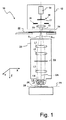
図1は、包括的に10によって示されるマイクロリソグラフィック投影露光装置を通る極めて略図化された縮尺に従っていない縦断面図を示している。投影露光装置10は、投影光ビーム13を生成するための光源14を伴う照明システム12を包含する。光源14は、たとえばエキシマ・レーザとすることができるが、短い波の投影光を生成する。この例示的な実施態様においては、投影光の波長が193nmである。たとえば、157nmまたは248nmといったほかの波長を使用することも同様に可能である。
FIG. 1 shows a longitudinal section through a micro-lithographic projection exposure apparatus, generally indicated by 10, which is not to very highly scaled. The
照明システム12は、さらに減偏光子17および視野開口18を伴う、16によって示されている照明光学系を含む。照明光学系16は、光源14によって生成された投影光ビームを所望の方法で再整形し、異なる照明角度分布のセットアップを可能にする。このため照明光学系16は、たとえば交換可能な回折光学エレメントおよび/またはマイクロレンズ・アレイを含むことができる。たとえば米国特許第6 285 443 A号を参照されたいが、その種の照明光学系16が従来技術において公知であることから、これについてのさらに詳細な説明は省略する。
The
照明システム12の対物鏡19は、視野開口18を、その後に続く投影対物鏡20の対物面上に鮮明に結像する。
The
投影対物鏡20は、多数のレンズおよびそのほかの光学エレメントを含み、図1には、簡明のため、それらのうちのいくつかだけ(L1〜L6によって示されている)が例として示されている。投影対物鏡20は、そのほかの光学エレメント、たとえばビーム経路を折り返すために使用される1つまたは複数のイメージング・ミラー、またはフィルタ・エレメントも含むことがある。たとえば13nmといった極度に短い波長の場合には、このように短い波長のために利用できる充分に透明なレンズ材料がないことから投影対物鏡20が結像エレメントとしてミラーだけを含む。同じことが、照明システム12について当て嵌まる。
投影対物鏡20は、投影対物鏡20の対物平面22内に配置可能であり、かつ投影光ビーム13によって照明されるマスク24の縮小された画像を、たとえばフォトレジストとすることができる感光層26上に投影するために使用される。層26は、投影対物鏡20の画像平面28内に配置され、支持29、たとえばシリコン・ウェファ上に与えられる。
The
照明システム12内および投影対物鏡20内に含まれるレンズには、反射防止コーティングが提供される。この反射防止コーティングの目的は、レンズの境界面において反射され、したがって投影が失われるか、または二重反射を招く光の割合を低減することである。コーティングは、一般に多数の薄い個別の層を含み、それらの屈折率および厚さは、投影光13の波長について望ましい特性が達成されるように選択される。
The lenses included in the
反射防止コーティングの場合であれば、それらの特性が、主として98%を超える非常に高い透過率になる。そのような高い透過率が、大きな入射角度範囲にわたって達成される必要がある。特に、非常に高開口の投影対物鏡20の場合には入射角が70°に至ることもあり、特定の場合にはそれを超えることさえある。入射角に対する透過率の依存が強すぎる場合には、これが、瞳に近いコーティングを伴って視野依存の構造の幅の変動を、近視野コーティングを伴って角度依存の構造の幅の変動を招くことになる。
In the case of anti-reflective coatings, these properties result in very high transmission, mainly exceeding 98%. Such high transmission needs to be achieved over a large incident angle range. In particular, in the case of a very high
さらに、レンズに与えられる反射防止コーティングには、それらが、入射投影光13の偏光状態に関わりなくそれらの光学的特性を有することが期待される。直交する偏光状態について反射防止コーティング内の透過率の変動が大きすぎる場合には、この偏光依存度が望ましくない結像誤りを招くことがある。これは、照明システム12内における減偏光子17の使用にもかかわらず、投影対物鏡20を通過するときに投影光13が完全に偏光が取り除かれずに残るという事実に関係する。その理由は、たとえば内在的な、または応力複屈折レンズ材料、偏光性マスク構造をはじめ、ここで反射防止および反射コーティングの場合について考察した偏光依存度であると見られる。
Furthermore, antireflection coatings applied to lenses are expected to have their optical properties regardless of the polarization state of the
反射防止コーティングが視野平面の近傍内に配置される場合には、投影光が視野にわたって変動する選択的な偏光方向を有するとき、その透過率における偏光依存度が画像野にわたって変動する強度を導く。視野平面内におけるその種の強度変動は、コンポーネント上の望ましくない視野依存の構造の幅の変動として顕在化する。これに対して、偏光依存の透過率を伴う反射防止コーティングが瞳の近傍に配置される場合には、すでに存在している偏光状態の角度依存度が同様に望ましくない構造の幅の変動を導くことがある。 When the anti-reflective coating is placed in the vicinity of the field plane, when the projection light has a selective polarization direction that varies across the field of view, the polarization dependence in its transmission leads to an intensity that varies across the image field. Such intensity variations in the field plane manifest themselves as undesirable field dependent structure width variations on the component. In contrast, when an anti-reflective coating with polarization-dependent transmission is placed near the pupil, the angular dependence of the already existing polarization state likewise leads to undesirable structure width variations. Sometimes.
この理由のため、反射防止コーティングの開発時には、直交する偏光状態についての透過係数の間の差ΔTを10%未満に、より好ましくは3%未満に維持する試みがなされる。 For this reason, when developing anti-reflective coatings, an attempt is made to maintain the difference ΔT between transmission coefficients for orthogonal polarization states below 10%, more preferably below 3%.
レンズおよびミラーの反射(防止)コーティングは、さらに、それらのコーティングを通過する光の位相を偏光状態の関数として変動させることがある。これは、コーティングを光学的に複屈折とし、画像平面内における結像品質に対して好ましくない効果を有する。この理由のため、直交する偏光状態の間における許容可能な位相差Δφは、投影光13の波長λの1/10未満とする必要がある。
Lens (and mirror) reflective (preventive) coatings may also cause the phase of light passing through them to vary as a function of polarization state. This makes the coating optically birefringent and has an undesirable effect on the imaging quality in the image plane. For this reason, the allowable phase difference Δφ between the orthogonal polarization states needs to be less than 1/10 of the wavelength λ of the
しかしながら、一方における高い平均透過率をはじめ、他方における透過率および位相の低い偏光依存度は、かなりの入射角度範囲にわたって達成することが不可能であるか、またはよくても極端に大きな出費を伴って達成可能である。 However, high average transmission on one side and low polarization dependence on transmission and phase on the other cannot be achieved over a considerable range of incident angles, or at best with extremely high expense. Can be achieved.
したがって本発明によれば、投影露光装置10内のコーティングが、透過係数の、および位相の偏光依存度が大きな入射角度範囲にわたって低く維持されるように構成される。しかしながら平均透過率および平均位相は、入射角度範囲にわたって知覚可能に変化することがある。同時に生じる結像の摂動は、比較的単純な方法で、たとえばグレイ・フィルタまたは−−位相誤りの場合であれば−−局所的な非軸対称表面ひずみの補助を伴って補正される。
Therefore, according to the present invention, the coating in the
実質的な偏光非依存度は、特に反射防止コーティングの場合に、相互に直交する偏光状態に対する透過係数の互いの相違が70°の入射角度範囲にわたって10%を超えないこと、好ましくは3%を超えないこと、より好ましくは1%を超えないことを意味する。同じことが反射コーティングの場合の反射係数について当て嵌まる。 Substantial polarization independence means that, particularly in the case of antireflection coatings, the difference in transmission coefficients for mutually orthogonal polarization states does not exceed 10% over the 70 ° incidence angle range, preferably 3%. It means not exceeding, more preferably not exceeding 1%. The same is true for the reflection coefficient in the case of a reflective coating.
そのような方法で構成される層システムは、比較的わずかな出費で開発および製造が可能である。これを行う方法の詳細は、標準的な教範、たとえばT.W.バウマイスター(T.W. Baumeister)著『オプティカル・コーティング・テクノロジ(Optical Coating Technology)』に見ることができる。 Layer systems constructed in such a way can be developed and manufactured with relatively little expense. Details of how to do this can be found in standard teachings such as T.C. W. It can be found in “Optical Coating Technology” by TW Baumeister.
図2は、相互に直交する偏光状態に対する透過係数の互いの相違が1%を超えない反射防止コーティング32の例示的実施態様の詳細の横断面を示している。反射防止コーティング32は、材料および光学的膜厚が表1に指定されている6つの薄い個別の層L1〜L6からなる。反射防止コーティング32は、たとえば石英ガラスからなるレンズ36の凹状の表面34上に与えられ、λ=193nmの波長用に構成される。量QWOT(1/4波長光学膜厚)は、光学的膜厚、すなわち1/4波長を単位で表した屈折率と幾何学的な厚さの積を言う。
FIG. 2 shows a detailed cross-section of an exemplary embodiment of an

原理的に同様に適切なものに、低い耐久性からあまり好ましくはないが、導入部分で引用したとおり、JP 2004−302113 Aの例示的実施態様4として述べられている3つの層から構成されるコーティングがある。同様に導入部分で述べたEP 0 994 368 A2は、より耐久性のある5つの層を有するコーティングについて述べているが、前述した0°から70°までの入射角度範囲において、直交する偏光状態に対する透過係数が互いから約5%異なる。
In principle equally suitable, less preferred from low durability, but as cited in the introductory part, consists of three layers described as
以下においては、光線30が二重矢印によって示されるp偏光成分38および黒丸によって示されるs偏光成分40の両方を含むことを前提とする。反射防止コーティング32に衝突する光の大半は、わずかに異なるs偏光成分40およびp偏光成分38それぞれに対する透過係数TsおよびTpを伴って透過されることになる。図2においては、このわずかな相違が、透過されたs偏光成分40については矢印42sによって示されており、透過されたp偏光成分38についての矢印42pよりいくぶん長い。
In the following, it is assumed that the
概して言えば、反射防止コーティング32の反射率もまた、入射光の偏光状態に従って異なり、図2においてはそれが44に誇張表現された方法で示されている。
Generally speaking, the reflectivity of the
反射防止コーティング32の平均透過率〈T〉は次の式(1)によって与えられる。
〈T〉=(|Ts|+|Tp|)/2 (1)
The average transmittance <T> of the
<T> = (| Ts | + | Tp |) / 2 (1)
透過率の偏光依存度は、透過係数TsとTpの間の差により、式(2)に従ってもっとも良好に記述される。
ΔT=|Ts|−|Tp| (2)
The polarization dependence of the transmittance is best described according to equation (2) due to the difference between the transmission coefficients Ts and Tp.
ΔT = | Ts | − | Tp | (2)
平均位相〈φ〉および位相差Δφについては、それぞれ式(3)および(4)が適用される。
〈φ〉=(arg(Ts)+arg(Tp))/2 (3)
Δφ=arg(Ts)−arg(Tp) (4)
Equations (3) and (4) are applied to the average phase <φ> and the phase difference Δφ, respectively.
<Φ> = (arg (Ts) + arg (Tp)) / 2 (3)
Δφ = arg (Ts) −arg (Tp) (4)
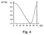
図3、4,および5は、平均透過率〈T〉、式(2)に従った透過係数間の差ΔT、および式(4)に従った位相差が、反射防止コーティング32について入射角αの関数としてそれぞれプロットされたグラフを示している。ΔT<1%およびΔφ<0.1・λが、70°の角度範囲にわたって当て嵌まることが理解できる。しかしながら平均透過率〈T〉は、この入射角度範囲にわたって一貫して98%より高くなく、むしろ大きい入射角については92%より低い値まで落ち込んでいる。これは、したがって前述した視野および/または角度依存の強度変動を導き得る。
3, 4, and 5 show that the average transmittance <T>, the difference ΔT between transmission coefficients according to equation (2), and the phase difference according to equation (4) are incident angles α for the
画像平面28内における強度変動を回避するために、同様に視野の近傍に位置決めされるグレイ・フィルタを使用することができる。これに代わるものとして、角度依存の透過率を伴うフィルタ・エレメントを瞳の近傍に位置決めすることも可能である。その種の角度依存グレイ・フィルタが、図1に50によって示されている。この状況に適しているグレイ・フィルタのこのほかの設計は、US 2005/0018312 A1号に見ることができる。
To avoid intensity fluctuations in the
走査型投影露光装置10においては、照明システム12内に、多数の個別に置換可能な開口エレメントを包含する視野開口を使用することも可能である。たとえばEP 0 952 491 A2内で述べられているとおり、それ自体は公知であるその種の視野開口は、画像平面28内における放射線量を、スリット形状の明視野の長さ方向のポジションの関数として変化させることを可能にする。
In the scanning
しかしながら反射防止コーティング32が瞳平面の近傍に位置する場合には、これが瞳アポダイゼーションを生成することになる。その種の瞳アポダイゼーションは、瞳平面の近傍の適切に構成された反射防止層によって補正できる。ゼルニケ係数Z2/Z3によって記述可能な瞳アポダイゼーションの傾きは、ミラー層によって補正できる。
However, if the
特定の角度において平均透過率〈T〉が低いことに起因して生じることがあるより強い二重反射は、散乱防止開口によって吸収できる。 Stronger double reflections that may arise due to the low average transmittance <T> at a particular angle can be absorbed by the anti-scatter aperture.
平均位相〈φ〉も同様に反射防止コーティングの最適化において優先権が与えられないことから、反射防止コーティング32に起因する位相誤りが結像誤りを導くことがある。
Similarly, since the average phase <φ> is not given priority in optimizing the antireflection coating, a phase error caused by the
その種の結像誤りは、少なくとも特定の範囲内において、それ自体は公知のマニプレータによって補正できる。特に良好な補正は、光学エレメント、またはここで別々に提供されているプレートの境界面に局所的に、かつ非軸対称にひずみが与えられるときに達成される。このひずみは、材料の追加または除去によって生成できるが、この場合、数ナノメートル台であり、好ましくは50ナノメートル未満である。 Such imaging errors can be corrected by a manipulator known per se, at least within a certain range. Particularly good correction is achieved when the optical element or the plate interface provided separately here is strained locally and non-axisymmetrically. This strain can be generated by the addition or removal of material, but in this case is on the order of a few nanometers, preferably less than 50 nanometers.
最小偏光依存度に関して個別の反射防止コーティングをそれぞれ最適化することに代えて、投影対物鏡20内に含まれる反射防止コーティングのいくつかまたはすべての、またオプションとして投影露光装置10全体を通じて包括的な最適化を行うことも可能である。その場合の前述した条件は、次のとおりに記述できる。
ΔTtotal<10%
好ましくは<3%、より好ましくは<1%であり、かつ
Δφtotal<λ/10。
Instead of optimizing each individual antireflective coating with respect to the minimum polarization dependence, some or all of the antireflective coatings contained within the
ΔTtotal <10%
Preferably <3%, more preferably <1%, and Δφtotal <λ / 10.
当然のことながら、上記の考察は、投影露光装置10内の湾曲結像ミラーまたは平面偏向ミラーに使用されるような反射コーティングにも当て嵌まる。
Of course, the above considerations also apply to reflective coatings such as those used for curved imaging mirrors or planar deflection mirrors in
以下、反射防止コーティングの種々の例示的実施態様について述べるが、それらのうちのいくつかは、直交する偏光状態対する透過係数間の差が特に小さい。そのほかの例示的実施態様においては、この差がより大きいが、それにもかかわらず特に高い平均透過係数および/または特に小さい分相がかなりの入射角度範囲にわたって達成される。なお、注意する必要があるが、ここからは透過係数Tを指定することによってではなく、反射係数Rを指定することによって透過性能を述べることになる。コーティングが無視できる吸収を有する場合には、T=1−Rが当て嵌まる。したがって小さい反射係数は大きい透過係数に対応し、その逆も同じである。 In the following, various exemplary embodiments of antireflection coatings are described, some of which have particularly small differences between transmission coefficients for orthogonal polarization states. In other exemplary embodiments, this difference is greater, but nevertheless a particularly high average transmission coefficient and / or a particularly small phase separation is achieved over a considerable incidence angle range. It should be noted that, from here on, the transmission performance will be described not by specifying the transmission coefficient T but by specifying the reflection coefficient R. If the coating has negligible absorption, T = 1−R applies. Thus, a small reflection coefficient corresponds to a large transmission coefficient and vice versa.
例示的実施態様2
表2は、合計で4つの層を包含する反射防止コーティングの例示的実施態様についての層仕様を与える。図6は、s偏光、p偏光、および非偏光に対する反射係数Rs、Rp、およびRaが、この反射防止コーティングについて入射角の関数としてそれぞれプロットされたグラフを示している。
Table 2 gives the layer specifications for an exemplary embodiment of an anti-reflective coating that includes a total of four layers. FIG. 6 shows a graph in which the reflection coefficients Rs, Rp, and Ra for s-polarized, p-polarized, and unpolarized light are plotted as a function of incident angle for this anti-reflective coating, respectively.
前述した例示的実施態様1の場合と同様に、層は、たとえばレンズまたは平面平行平板とすることができる支持材料から開始してカウントされる。193nmの波長において約1.56の屈折率を有するCaF2が、この例示的実施態様および以下に述べる実施態様の支持(サブストレート)の材料として採用されることになる。しかしながら、ほかの支持材料、たとえば合成石英ガラス(SiO2)またはフッ化バリウム(BaF2)を使用することも可能であり、反射防止コーティングの光学特性は、これによって比較的わずかしか変更されない。
As in the
193nmの波長において約1.69の屈折率を有するフッ化ランタン(LaF3)は、より高い屈折性の層のために採用された。同じ波長において約1.43の屈折率を有するフッ化マグネシウム(MgF2)は、より低い屈折性の層のために採用された。これらの層を製造するために、公知の製造方法、たとえばPVDまたはCVD方法を採用することができる。 Lanthanum fluoride (LaF3), which has a refractive index of about 1.69 at a wavelength of 193 nm, was employed for the higher refractive layer. Magnesium fluoride (MgF2) having a refractive index of about 1.43 at the same wavelength was employed for the lower refractive layer. In order to produce these layers, known production methods such as PVD or CVD methods can be employed.
当然のことながら、より高い屈折性の層およびより低い屈折性の層のための前述した材料は、類似の屈折率を伴うほかの材料にそれぞれ置き換えてもよい。LaF3のほかに、より高い屈折性の材料として、特にNdF3、Al2O3、およびErF3も適している。MgF2のほかに、より低い屈折性の材料として、たとえばAlF3、チオライト、またはクリオライトも考えられる。これらの材料が、表2の中で述べている材料といくぶん異なる屈折率を有することから、その中にQWOT(1/4波長光学膜厚)の単位で指定されている光学膜厚について差が生じることがある。それらが、表2の最後の行に範囲指定の形で述べられている。LaF3およびMgF2を採用する場合であっても、たとえば微調整を行うために、表中の値範囲内の光学膜厚の使用が得策となることがある。 Of course, the materials described above for the higher and lower refractive layers may each be replaced with other materials with similar refractive indices. In addition to LaF3, NdF3, Al2O3 and ErF3 are also particularly suitable as higher refractive materials. Besides MgF2, for example, AlF3, thiolite or cryolite are also conceivable as lower refractive materials. Since these materials have a refractive index somewhat different from the materials described in Table 2, there is a difference in the optical film thickness specified in units of QWOT (1/4 wavelength optical film thickness). May occur. They are stated in the last row of Table 2 in the form of a range specification. Even when LaF3 and MgF2 are employed, it may be advantageous to use an optical film thickness within the range of values in the table, for example, for fine adjustment.
上記のより高い、およびより低い屈折性材料の共通の特徴は、それらによって約1.60と1.92の間の範囲内または約1.37と1.44の間の範囲内の屈折率が、パッキング密度を85%の値より下に減少させることなくそれぞれ達成されることが可能であるということである。それらの層は、したがってより耐久性があり、長期の動作時間の後および異なる環境効果の下においてさえ実質的に光学特性が変化しない。 The common feature of the above higher and lower refractive materials is that they provide a refractive index in the range between about 1.60 and 1.92 or in the range between about 1.37 and 1.44. It can be achieved without reducing the packing density below the value of 85%, respectively. These layers are therefore more durable and do not substantially change their optical properties after prolonged operating times and even under different environmental effects.
図6に示されているグラフは、この4層だけからなる反射防止コーティングを用いれば、s偏光およびp偏光に対する反射係数RsおよびRpが、0°と60°の間の入射角度範囲にわたって互いに非常にわずかしか変化しないこと、詳細には1%を超えないことを明らかにしている。0°と50°の間の入射角度範囲については、差だけでなく、反射係数RsおよびRpの絶対値も1%未満になっている。 The graph shown in FIG. 6 shows that with this four-layer antireflection coating, the reflection coefficients Rs and Rp for s-polarized light and p-polarized light are very close to each other over an incident angle range between 0 ° and 60 °. It shows that it changes only slightly, and in detail, it does not exceed 1%. For the incident angle range between 0 ° and 50 °, not only the difference but also the absolute values of the reflection coefficients Rs and Rp are less than 1%.
この反射防止コーティングの特有の特徴は、約35°と55°の間の入射角についてs偏光に対する反射係数Rsが、p偏光に対する反射係数Rpより小さいことである。その種の−−55°を超える入射角度範囲についてではあるが−−導入部分で引用したJP 2004−302113の中で最初に述べられた振る舞いは、フレネルの式によればp偏光がs偏光より原則的に良好に透過されることから異常である。 A unique feature of this anti-reflective coating is that the reflection coefficient Rs for s-polarized light is smaller than the reflection coefficient Rp for p-polarized light for incident angles between about 35 ° and 55 °. For that kind of incident angle range above 55 °, but the behavior first described in JP 2004-302113 cited in the introductory part, p-polarized light is more s-polarized according to Fresnel's equation. In principle, it is abnormal because it penetrates well.
反射の振る舞いのこの逆転は、それ自体新しくはないが、特定の角度範囲にわたってほかのコーティングにおける従来的な偏光依存の反射の振る舞いに起因する効果の補償に好適に使用することが可能である。第1の例示的実施態様およびその後に続く例示的実施態様のいくつかによって示されるとおりにs偏光およびp偏光に対する反射係数間の差を非常に小さく維持することが可能であるとしても、それにもかかわらずこれは、相応じて製造が精巧になる6つまたはそれより多くの個別の層を伴うより複雑な層システムをしばしば必要とする。しかしながら、図6に示されている特性を有する反射防止コーティングが、ある入射角度範囲にわたってp偏光に対するより高いs偏光に対する反射率を有する別の単純に構成された反射防止コーティングと組み合わされるとすれば、偏光に中立の振る舞いが全体として達成可能である。 This reversal of the reflection behavior is not new per se, but can be suitably used to compensate for the effects due to conventional polarization-dependent reflection behavior in other coatings over a specific angular range. Even if it is possible to keep the difference between the reflection coefficients for s-polarized light and p-polarized light very small as shown by the first exemplary embodiment and some of the exemplary embodiments that follow it, Regardless, this often requires a more complex layer system with six or more individual layers that are correspondingly sophisticated to manufacture. However, if an anti-reflective coating having the properties shown in FIG. 6 is combined with another simply constructed anti-reflective coating having a higher reflectivity for s-polarized light over p-polarized light over a range of incident angles. Overall, polarization neutral behavior can be achieved.
このために、偏光依存度を互いに補償することが意図された反射防止コーティングが同一の入射角度範囲内において記述された振る舞いを呈するべきとすることは、無条件に必要とならない。一方の光学表面に大きな入射角で衝突する光線が、他方の光学表面に小さい入射角で衝突することができ、その逆も当て嵌まる。Rs>RpおよびRs<Rpを伴う範囲を有するまったく同じに構成された2つの反射防止コーティングが、このような方法で選択された光学表面上に与えられた場合には、それらの偏光依存度を互いに中立化できる。しかしながら概して、補償する反射防止コーティングが光学エレメントの、たとえばレンズの入口および出口表面に与えられるとき、状況がもっとも単純になる。これは、光学システムが構成されるとき、光学レンズの入口および出口表面上の入射角を類似にすることがしばしば試みられることによる。しかしながら、反射防止コーティングの間にそのほかの多くの光学エレメントが存在する場合には、それらの間にある光学エレメントによって入射角の分布が比較的複雑な方法で変更されることがある。 For this reason, it is not unconditionally necessary that anti-reflection coatings intended to compensate for polarization dependence with each other should exhibit the described behavior within the same incident angle range. Light rays that collide with one optical surface with a large incident angle can collide with the other optical surface with a small incident angle, and vice versa. If two identically configured anti-reflective coatings with ranges with Rs> Rp and Rs <Rp are applied on an optical surface selected in this way, their polarization dependence is reduced. Can neutralize each other. In general, however, the situation is simplest when a compensating anti-reflective coating is applied to the optical element, for example the entrance and exit surfaces of the lens. This is because when an optical system is constructed, it is often attempted to make the incident angles on the entrance and exit surfaces of the optical lens similar. However, if many other optical elements are present between the antireflective coatings, the optical angle between them can change the distribution of incident angles in a relatively complex manner.
理解される必要があるが、表2に与えられている層仕様が光学エレメントの全表面にわたってまったく同じである必要はない。光学エレメント上の異なる領域がしばしば入射角の異なる分布にさらされることから、それぞれが出会う角度スペクトルに最適に適合された異なる反射防止コーティングが異なる領域上に与えられることが得策となり得る。 It should be understood that the layer specifications given in Table 2 need not be exactly the same across the entire surface of the optical element. Since different regions on the optical element are often exposed to different distributions of incident angles, it can be advisable to provide different anti-reflective coatings on different regions that are optimally adapted to the angular spectrum they meet.
例示的実施態様3
表3は、合計で8つの層を包含する反射防止コーティングの例示的実施態様についての層仕様を与える。図7は、s偏光、p偏光、および非偏光に対する反射係数Rs、Rp、およびRaが、この反射防止コーティングについて入射角の関数としてそれぞれプロットされたグラフを示している。
Table 3 provides the layer specifications for an exemplary embodiment of an antireflective coating that includes a total of eight layers. FIG. 7 shows a graph in which the reflection coefficients Rs, Rp, and Ra for s-polarized, p-polarized, and unpolarized light are plotted as a function of incident angle for this anti-reflective coating, respectively.
図7のグラフを見ると、この場合には約40°を超える入射角における反射の振る舞いが、s偏光がp偏光よりはるかに少なく反射されることから、本質的に従来的な振る舞いと異なることがわかる。反射係数RsとRpの負の差ΔR=Rs−Rpは、約50°の入射角において、JP 2004−302113の図12の補助を伴って示される反射防止コーティングの場合より実質的にはるかに強く増加している。表3の中で与えられている層仕様を用いる反射防止コーティングは、したがって、例示的実施態様2に関連して前述したとおり、ほかの層の偏光依存度の補償にさらに良好に使用できる。
Looking at the graph of FIG. 7, in this case the reflection behavior at an incident angle above about 40 ° is essentially different from the conventional behavior because s-polarized light is reflected much less than p-polarized light. I understand. The negative difference ΔR = Rs−Rp between the reflection coefficients Rs and Rp is substantially much stronger at the incident angle of about 50 ° than in the antireflection coating shown with the aid of FIG. 12 of JP 2004-302113. It has increased. An antireflective coating using the layer specifications given in Table 3 can therefore be used better to compensate for the polarization dependence of other layers, as described above in connection with
JP 2004−302113に記述された反射防止コーティングを超える実質的な利点は、特に、85%を超えるパッキング密度を有する層だけがここで述べている反射防止コーティング内に使用されることである。しかしながら、JP 2004−302113の中で述べられている例示的実施態様においては、1.21の低屈折率を達成できるようにするために最下層のパッキング密度が49%しかない。このタイプの低いパッキング密度は、その種の稠密でない層が環境効果の影響を受けやすく、したがって、時間の関数として比較的短時間でその光学特性を変化させることから不都合である。 A substantial advantage over the antireflective coating described in JP 2004-302113 is that, in particular, only layers having a packing density of greater than 85% are used in the antireflective coating described herein. However, in the exemplary embodiment described in JP 2004-302113, the bottom layer packing density is only 49% in order to be able to achieve a low refractive index of 1.21. This type of low packing density is disadvantageous because such a dense layer is susceptible to environmental effects and thus changes its optical properties in a relatively short time as a function of time.
例示的実施態様4
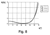
表4は、合計で7つの層を包含する反射防止コーティングの別の例示的実施態様についての層仕様を与える。図8は、s偏光、p偏光、および非偏光に対する反射係数が、この反射防止コーティングについて入射角の関数としてそれぞれプロットされたグラフを示している。
Table 4 provides layer specifications for another exemplary embodiment of an antireflective coating that includes a total of seven layers. FIG. 8 shows a graph in which the reflection coefficients for s-polarized light, p-polarized light, and non-polarized light are plotted as a function of incident angle for this anti-reflective coating, respectively.
s偏光およびp偏光に対する反射係数は、0°と60°の入射角の間において非常にわずかしか変化せず、詳細には0.1%を超えない。4%においては、約20°と50°の間の角度範囲内で絶対値RsおよびRpが同様に非常に類似している。この反射防止コーティングは、したがって、前述の範囲内の入射角を伴って光が斜めにだけ、または少なくとも主として斜めに衝突する光学エレメントに特に適している。 The reflection coefficients for s-polarized light and p-polarized light vary very little between 0 ° and 60 ° incidence angles, in particular not exceeding 0.1%. At 4%, the absolute values Rs and Rp are likewise very similar within an angular range between about 20 ° and 50 °. This anti-reflective coating is therefore particularly suitable for optical elements in which light impinges only at an angle, or at least mainly at an angle, with an angle of incidence within the aforementioned range.
表4の中で与えられている層仕様を用いる反射防止コーティングは、反射防止コーティングを通過した後のs偏光とp偏光の間における最小位相差Δφを達成するためにも最適化されている。小さい位相差Δφを得るためには、コーティングが可能な限り少ない層からなり、しかも少なくとも提供される層の厚さが可能な限り小さいことが好ましい。表4の中で与えられている層仕様と、例示的実施態様3の表3の中で与えられている層仕様を比較すると、この法則が満足され得ることがわかり、それによって許容不能に大きな差ΔR=Rs−Rpは伴うことはない。例示的実施態様4においては、0°と50°の間の入射角に対して0.5°未満であり、かつ70°の入射角まで約6°に達しない位相差が達成される。
Antireflective coatings using the layer specifications given in Table 4 are also optimized to achieve a minimum phase difference Δφ between s-polarized light and p-polarized light after passing through the antireflective coating. In order to obtain a small phase difference Δφ, it is preferred that the coating consists of as few layers as possible, and at least the thickness of the provided layer is as small as possible. Comparing the layer specifications given in Table 4 with the layer specifications given in Table 3 of
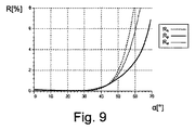
すべての層が、表4の中で与えられている層仕様に基づいて約7%薄く作られる場合には、特に小さい反射係数を伴う範囲が、図9のグラフによって明らかにされるとおり、より小さい入射角にシフトされることになる。この変更は、反射防止コーティングを0°と約40°の間の入射角に特に適したものにする。この入射角度範囲においては、s偏光およびp偏光に対する反射係数RsおよびRpがいずれも約0.2%未満であり、それらの反射係数の間の差ΔRは、より小さい大きさの位数である。ここでは、位相差Δφも同様に、より小さい入射角にシフトされる。したがって、70°の入射角における位相差Δφはいくぶん大きく、詳細には10°になる。 If all layers are made about 7% thinner based on the layer specifications given in Table 4, the range with a particularly small reflection coefficient is more evident as shown by the graph in FIG. It will be shifted to a small incident angle. This modification makes the antireflective coating particularly suitable for incident angles between 0 ° and about 40 °. In this incident angle range, the reflection coefficients Rs and Rp for s-polarized light and p-polarized light are both less than about 0.2%, and the difference ΔR between the reflection coefficients is a smaller magnitude order. . Here, the phase difference Δφ is similarly shifted to a smaller incident angle. Therefore, the phase difference Δφ at an incident angle of 70 ° is somewhat large, specifically 10 °.
例示的実施態様5
例示的実施態様2および3においても、特に、より厚い層をより薄くすることが可能であれば、分相を低減することができる。
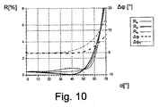
Also in the
表5は、例示的実施態様3について表3の中に示されていた層仕様に基づく反射防止コーティングのための層仕様を示している。そこに規定されていたより厚い層2、4、および5が、ここでは、はるかに薄くなっている。
Table 5 shows the layer specifications for the anti-reflective coating based on the layer specifications shown in Table 3 for
図10は、s偏光、p偏光、および非偏光に対する反射係数が、この反射防止コーティングについて入射角の関数としてそれぞれプロットされたグラフを示している。例示的実施態様5についての位相差Δφは破線のラインを用いて、例示的実施態様3については、比較のために一点鎖線を用いてプロットされている。はるかに小さい位相差Δφが層の厚さの低減によって約30°を超える入射角に伴うことが明確に理解できる。それに対して反射の振る舞いは、図10と7の比較によって示されるとおり、実行された修正によって有意に損なわれていない。
FIG. 10 shows a graph in which the reflection coefficients for s-polarized light, p-polarized light, and unpolarized light are plotted as a function of incident angle for this anti-reflective coating, respectively. The phase difference Δφ for
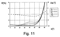
例示的実施態様6
表6は、合計で8つの層を包含する反射防止コーティングの別の例示的実施態様についての層仕様を与える。図11は、図10に対応するグラフを示しており、そこには、p偏光、s偏光、および非偏光に対する反射係数をはじめ、位相差Δφが入射角の関数としてプロットされている。
Exemplary Embodiment 6
Table 6 provides the layer specifications for another exemplary embodiment of an antireflective coating that includes a total of eight layers. FIG. 11 shows a graph corresponding to FIG. 10, in which the phase difference Δφ is plotted as a function of incident angle, including the reflection coefficients for p-polarized light, s-polarized light, and non-polarized light.
この例示的実施態様に従った反射防止コーティングは、特に小さい位相差によって特徴付けられ、その絶対値は、0°と70°の間の入射角度範囲を通して5°を超えない。この反射防止コーティングでは、さらに、0°と約65°の間の角度範囲において位相差Δφが負になることが注目される。これは、この入射角度範囲内においては、その反射防止コーティングを通過するp偏光が、s偏光に対して遅延を伴うことを意味する。この普通でない振る舞いは、反射係数Rs、Rpについて例示的実施態様2に関連して前述した方法と類似の方法で正の位相差の補償に使用することができる。ここでもまた、正の位相差を有する少なくとも1つの反射防止コーティングと負の分相を有する別の反射防止コーティングの組み合わせが、それら2つの反射防止コーティングを通過した後にs偏光およびp偏光が有意の位相差を持たなくなっているという効果を達成可能であることが事実となる。
The anti-reflective coating according to this exemplary embodiment is characterized by a particularly small phase difference, whose absolute value does not exceed 5 ° through an incident angle range between 0 ° and 70 °. It is further noted that with this anti-reflective coating, the phase difference Δφ is negative in the angular range between 0 ° and about 65 °. This means that within this incident angle range, p-polarized light passing through the anti-reflection coating is delayed with respect to s-polarized light. This unusual behavior can be used to compensate for positive phase differences in a manner similar to that described above in connection with
この場合には、たとえば、相当な正の位相差に対する多数の反射防止コーティングの寄与が、負の位相差を伴う単一の反射防止コーティングまたはいくつかの反射防止コーティングによって補償されることも可能である。ここでもまた、正の位相差を伴う反射防止コーティングと負の位相差を伴うものの角度範囲が必ずしも一致する必要はない。 In this case, for example, the contribution of multiple antireflection coatings to a substantial positive phase difference can be compensated by a single antireflection coating or several antireflection coatings with a negative phase difference. is there. Again, the angular range of the antireflective coating with a positive phase difference and that with a negative phase difference need not necessarily match.
コンピュータ補助最適化方法、たとえば変分方法を、異なる反射防止コーティングの組み合わせによって、反射率および位相に関する実質的に偏光に中立の振る舞いを達成するために採用してもよい。 Computer aided optimization methods, such as variational methods, may be employed to achieve a substantially polarization neutral behavior with respect to reflectivity and phase by a combination of different anti-reflective coatings.
概して言えば、第1の段階において、直交する偏光状態に対する反射率に全体として最小の差が得られるように反射防止コーティングを最適化することがもっとも単純となろう。第2の段階においては、1つまたはいくつか、たとえば4つの反射防止コーティングに残存する位相差を低減することができる。当然のことながら、位相差の低減を伴って開始し、その後に続いて反射率を最適化することによって逆の手順を採用してもよい。反射率および位相差両方に関する同時の最適化も原理的に可能である。 Generally speaking, in the first stage, it would be simplest to optimize the anti-reflective coating so that the overall difference in reflectivity for orthogonal polarization states is obtained. In the second stage, the phase difference remaining in one or several, eg four anti-reflective coatings can be reduced. Of course, the reverse procedure may be employed by starting with a phase difference reduction followed by optimizing the reflectivity. Simultaneous optimization of both reflectivity and phase difference is also possible in principle.
10 マイクロリソグラフィック投影露光装置;投影露光装置
12 照明システム
13 投影光ビーム;投影光
14 光源
16 照明光学系
17 減偏光子
18 視野開口
19 対物鏡
20 投影対物鏡
22 対物平面
24 マスク
26 感光層;層
28 イメージ平面
29 支持
30 光線
32 反射防止コーティング
34 表面
36 レンズ
38 p偏光成分
40 s偏光成分
DESCRIPTION OF
Claims (39)
前記反射防止コーティング(32)は、相互に直交する偏光状態(42p,42s)に対する前記反射防止コーティングの透過係数の互いの相違が0°から70°までの入射角度範囲にわたって10%を超えない、好ましくは3%を超えない、より好ましくは1%を超えないように構成されると共に構成されると共に
前記投影露光装置は、強度分布を均質化するための手段(50)を具備すること、
を特徴とするマイクロリソグラフィック投影露光装置。 A microlithographic projection exposure apparatus having an optical element (36) with an anti-reflective coating (32) to reduce reflectivity,
The antireflection coating (32) has a difference in transmission coefficient of the antireflection coating with respect to mutually orthogonal polarization states (42p, 42s) that does not exceed 10% over an incident angle range from 0 ° to 70 °; Preferably configured not to exceed 3%, more preferably not to exceed 1%, and the projection exposure apparatus comprises means (50) for homogenizing the intensity distribution;
A microlithographic projection exposure apparatus.
前記反射コーティングは、相互に直交する偏光状態に対する前記コーティングの反射係数の互いの相違が0°から70°までの入射角度範囲にわたって10%を超えない、好ましくは3%を超えない、より好ましくは1%を超えないように構成されると共に、
前記投影露光装置が、強度分布を均質化するための手段を具備すること、
を特徴とするマイクロリソグラフィック投影露光装置。 A microlithographic projection exposure apparatus having an optical element with a reflective coating to increase reflectivity,
The reflective coating has a difference in reflection coefficient of the coating with respect to mutually orthogonal polarization states that does not exceed 10%, preferably does not exceed 3%, more preferably over an incident angle range from 0 ° to 70 °. Configured to not exceed 1%,
The projection exposure apparatus comprises means for homogenizing the intensity distribution;
A microlithographic projection exposure apparatus.
前記反射防止コーティングは、相互に直交する偏光状態に対する前記複数の反射防止コーティングの透過係数の互いの相違が総合的な効果に関して0°から70°までの入射角度範囲にわたって10%を超えない、好ましくは3%を超えない、より好ましくは1%を超えないように構成されると共に、
前記投影露光装置は、強度分布を均質化するための手段を具備すること、
を特徴とするマイクロリソグラフィック投影露光装置。 A microlithographic projection exposure apparatus having a plurality of optical elements with anti-reflection coatings to reduce reflectivity,
The antireflection coating preferably has a difference in transmission coefficient of the plurality of antireflection coatings with respect to mutually orthogonal polarization states that does not exceed 10% over an incident angle range of 0 ° to 70 ° with respect to the overall effect, Is configured not to exceed 3%, more preferably not exceeding 1%,
The projection exposure apparatus comprises means for homogenizing the intensity distribution;
A microlithographic projection exposure apparatus.
前記反射コーティングは、相互に直交する偏光状態に対する前記複数の反射コーティングの反射係数の互いの相違が総合的な効果に関して0°から70°までの入射角度範囲にわたって10%を超えない、好ましくは3%を超えない、より好ましくは1%を超えないように構成されると共に、
前記投影露光装置は、強度分布を均質化するための手段を具備すること、
を特徴とするマイクロリソグラフィック投影露光装置。 A microlithographic projection exposure apparatus having a plurality of optical elements with a reflective coating to increase reflectivity,
The reflective coating has a difference in reflection coefficient of the plurality of reflective coatings relative to mutually orthogonal polarization states that does not exceed 10% over an incident angle range from 0 ° to 70 ° with respect to the overall effect, preferably 3 %, More preferably not more than 1%, and
The projection exposure apparatus comprises means for homogenizing the intensity distribution;
A microlithographic projection exposure apparatus.
相互に直交する偏光状態(42p,42s)に対する前記反射防止コーティングの透過係数は互いに0°から70°までの入射角度範囲にわたって1%を超えない範囲にあり、且つ前記層のいずれもが前記反射防止コーティングが対応する動作波長に対して1.35より小さい屈折率を有していないこと、
を特徴とする光学エレメント。 An optical element of a microlithographic projection exposure apparatus comprising an antireflective coating having a support material layer and a plurality of layers provided thereon,
The transmission coefficient of the antireflection coating for mutually orthogonal polarization states (42p, 42s) is in a range not exceeding 1% over an incident angle range of 0 ° to 70 ° with respect to each other, and any of the layers is the reflection The protective coating does not have a refractive index less than 1.35 for the corresponding operating wavelength;
An optical element characterized by
前記反射防止コーティングは、0°と60°の間にある少なくとも10°を構成する入射角度範囲内でs偏光をp偏光より少なく反射すること、
を特徴とする光学エレメント。 An optical element of a microlithographic projection exposure apparatus comprising an antireflective coating having a support material layer and a plurality of layers disposed thereon,
The anti-reflective coating reflects s-polarized light less than p-polarized light within an incident angle range comprising at least 10 ° between 0 ° and 60 °;
An optical element characterized by
前記反射防止コーティングは、0°と70°の間にある少なくとも10°を構成する入射角度範囲内においてs偏光をp偏光より少なく反射し、且つ前記層のいずれも前記反射防止コーティングが対応する動作波長に対して1.35より小さい屈折率を有していないことを特徴とする光学エレメント。 An optical element of a microlithographic projection exposure apparatus comprising an antireflective coating having a support material layer and a plurality of layers disposed thereon,
The anti-reflective coating reflects s-polarized light less than p-polarized light within an incident angle range that constitutes at least 10 ° between 0 ° and 70 °, and any of the layers corresponds to the anti-reflective coating. An optical element having no refractive index smaller than 1.35 with respect to a wavelength.
相互に直交する偏光状態(42p,42s)に対する前記反射防止コーティングの透過係数の互いの相違が0°から60°までの入射角度範囲にわたって0.2%を超えないことを特徴とする光学エレメント。 An optical element of a microlithographic projection exposure apparatus comprising an antireflective coating having a support material layer and a plurality of layers disposed thereon,
An optical element characterized in that the difference in transmission coefficient of the anti-reflection coating for mutually orthogonal polarization states (42p, 42s) does not exceed 0.2% over an incident angle range from 0 ° to 60 °.
λを動作波長とするとき、前記支持材料層から数えて2番目に最外側の層が1.2λ/4を超える光学的膜厚を有し、かつ3番目に最外側の層が0.8と1.5λ/4の間の光学的膜厚を有することを特徴とする光学エレメント。 An optical element of a microlithographic projection exposure apparatus comprising an antireflective coating having a support material layer and at least four layers disposed thereon,
When λ is an operating wavelength, the second outermost layer counted from the support material layer has an optical film thickness exceeding 1.2λ / 4, and the third outermost layer is 0.8. And an optical film thickness between 1.5λ / 4.
λを動作波長とするとき、前記支持材料層から数えて2番目に最外側の層が1.2λ/4を超える光学的膜厚を有し、かつ3番目に最外側の層が0.8と1.5λ/4の間の光学的膜厚を有することを特徴とする光学エレメント。 An optical element of a microlithographic projection exposure apparatus having a support material layer and an anti-reflective coating provided thereon,
When λ is an operating wavelength, the second outermost layer counted from the support material layer has an optical film thickness exceeding 1.2λ / 4, and the third outermost layer is 0.8. And an optical film thickness between 1.5λ / 4.
相互に直交する偏光状態(42p,42s)の位相の互いの相違が、0°から70°までの入射角度範囲にわたって前記反射防止コーティングを通過した後の大きさにおいて8°を超えないことを特徴とする光学エレメント。 An optical element of a microlithographic projection exposure apparatus comprising an antireflective coating having a support material layer and a plurality of layers disposed thereon,
The difference between the phases of mutually orthogonal polarization states (42p, 42s) does not exceed 8 ° in magnitude after passing through the antireflection coating over an incident angle range of 0 ° to 70 °. An optical element.
λを前記投影露光装置の動作波長とするとき、0.4λ/4より小さい光学的膜厚を有する少なくとも3つの層を具備したことを特徴とする光学エレメント。 An optical element of a microlithographic projection exposure apparatus comprising an antireflective coating having a support material layer and a plurality of layers disposed thereon,
An optical element comprising at least three layers having an optical film thickness smaller than 0.4λ / 4, where λ is an operating wavelength of the projection exposure apparatus.
λを前記投影露光装置の動作波長とするとき、少なくとも2つの第1の層は0.4λ/4より小さい光学的膜厚を有し、前記第1の層とは異なる少なくとも2つの第2の層が0.6λ/4より小さい光学的膜厚を有することを特徴とする光学エレメント。 An optical element of a microlithographic projection exposure apparatus comprising a support material layer and an antireflective coating having a plurality of layers applied thereon,
When λ is the operating wavelength of the projection exposure apparatus, at least two first layers have an optical film thickness smaller than 0.4λ / 4, and at least two second layers different from the first layer. An optical element characterized in that the layer has an optical film thickness of less than 0.6λ / 4.
少なくとも1つの第2の反射防止コーティングが第2の入射角度範囲内においてs偏光に対するよりs偏光に対する方が小さい反射率を有し、前記少なくとも1つの第1の反射防止コーティングおよび前記少なくとも1つの第2の反射防止コーティングが、それらが前記反射率における偏光依存の差を少なくとも部分的に補償するように前記ビーム経路内に配置されること、
を特徴とするマイクロリソグラフィック投影露光装置。 A microlithographic projection exposure apparatus having a plurality of optical elements with an anti-reflective coating to reduce reflectivity, wherein at least one first anti-reflective coating is more sensitive to p-polarized light within a first incident angle range. have greater reflectivity for s-polarized light,
At least one second anti-reflective coating has a lower reflectance for s-polarized light than for s-polarized light within a second incident angle range, the at least one first anti-reflective coating and the at least one first anti-reflective coating. Two anti-reflective coatings are disposed in the beam path such that they at least partially compensate for polarization dependent differences in the reflectivity;
A microlithographic projection exposure apparatus.
Applications Claiming Priority (2)
| Application Number | Priority Date | Filing Date | Title |
|---|---|---|---|
| DE102005041938A DE102005041938A1 (en) | 2005-09-03 | 2005-09-03 | Microlithographic projection exposure machine |
| PCT/EP2006/008605 WO2007025783A2 (en) | 2005-09-03 | 2006-09-04 | Microlithographic projection lighting system |
Publications (2)
| Publication Number | Publication Date |
|---|---|
| JP2009507366A true JP2009507366A (en) | 2009-02-19 |
| JP2009507366A5 JP2009507366A5 (en) | 2009-10-08 |
Family
ID=37421186
Family Applications (1)
| Application Number | Title | Priority Date | Filing Date |
|---|---|---|---|
| JP2008528432A Ceased JP2009507366A (en) | 2005-09-03 | 2006-09-04 | Microlithographic projection exposure apparatus |
Country Status (5)
| Country | Link |
|---|---|
| US (4) | US20080297754A1 (en) |
| JP (1) | JP2009507366A (en) |
| KR (1) | KR20080039469A (en) |
| DE (1) | DE102005041938A1 (en) |
| WO (1) | WO2007025783A2 (en) |
Cited By (1)
| Publication number | Priority date | Publication date | Assignee | Title |
|---|---|---|---|---|
| JP2013042155A (en) * | 2009-08-13 | 2013-02-28 | Carl Zeiss Smt Gmbh | Catadioptric projection objective |
Families Citing this family (5)
| Publication number | Priority date | Publication date | Assignee | Title |
|---|---|---|---|---|
| DE102005041938A1 (en) | 2005-09-03 | 2007-03-08 | Carl Zeiss Smt Ag | Microlithographic projection exposure machine |
| JP2008135127A (en) * | 2006-11-29 | 2008-06-12 | Konica Minolta Opto Inc | Optical element and optical pickup device |
| US7929115B2 (en) | 2007-06-01 | 2011-04-19 | Carl Zeiss Smt Gmbh | Projection objective and projection exposure apparatus for microlithography |
| CN109068044B (en) * | 2018-09-28 | 2023-11-03 | 武汉华星光电技术有限公司 | Optical module and display device |
| CN117192908B (en) * | 2023-08-22 | 2024-04-09 | 安徽国芯智能装备有限公司 | Compensation method for expansion and contraction consistency of direct-writing type photoetching machine |
Citations (10)
| Publication number | Priority date | Publication date | Assignee | Title |
|---|---|---|---|---|
| JPH08148411A (en) * | 1994-11-24 | 1996-06-07 | Nikon Corp | Projecting aligner |
| JP2000058442A (en) * | 1998-04-21 | 2000-02-25 | Asm Lithography Bv | Lithographic projection apparatus |
| JP2000357654A (en) * | 1998-10-13 | 2000-12-26 | Nikon Corp | Antireflection film, optical element, aligner and electronic component |
| WO2001023914A1 (en) * | 1999-09-30 | 2001-04-05 | Nikon Corporation | Optical device with multilayer thin film and aligner with the device |
| JP2002189101A (en) * | 2000-12-21 | 2002-07-05 | Nikon Corp | Antireflection film, optical element and exposure device |
| WO2003003429A1 (en) * | 2001-06-28 | 2003-01-09 | Nikon Corporation | Projection optical system, exposure system and method |
| US20030090638A1 (en) * | 2001-09-05 | 2003-05-15 | Carl Zeiss Semiconductor Manufacturing Technologies Ag | Zoom system for an illumination device |
| JP2004302113A (en) * | 2003-03-31 | 2004-10-28 | Nikon Corp | Antireflection film, optical member, optical system and projection exposure apparatus, and manufacturing method for antireflection film |
| US20050018312A1 (en) * | 2003-07-01 | 2005-01-27 | Carl Zeiss Smt Ag | Projection lens for a microlithographic projection exposure apparatus |
| WO2005069078A1 (en) * | 2004-01-19 | 2005-07-28 | Carl Zeiss Smt Ag | Microlithographic projection exposure apparatus with immersion projection lens |
Family Cites Families (11)
| Publication number | Priority date | Publication date | Assignee | Title |
|---|---|---|---|---|
| US6285443B1 (en) | 1993-12-13 | 2001-09-04 | Carl-Zeiss-Stiftung | Illuminating arrangement for a projection microlithographic apparatus |
| JP3924806B2 (en) | 1996-06-10 | 2007-06-06 | 株式会社ニコン | Anti-reflection coating |
| EP0952491A3 (en) | 1998-04-21 | 2001-05-09 | Asm Lithography B.V. | Lithography apparatus |
| US6243203B1 (en) * | 1998-04-24 | 2001-06-05 | U.S. Philips Corporation | Optical system with anti-reflection coating |
| EP0994368A3 (en) * | 1998-10-13 | 2000-05-03 | Nikon Corporation | Anti-reflective films, optical elements and reduction-projection exposure apparatus utilizing same |
| EP1227344A4 (en) * | 1999-11-05 | 2005-08-31 | Asahi Glass Co Ltd | Antireflection base for ultraviolet and vacuum ultraviolet regions |
| DE10240598A1 (en) * | 2002-08-27 | 2004-03-25 | Carl Zeiss Smt Ag | Catadioptric reflective/reduction lens for mapping an image pattern transfers a picture of the pattern in an object plane into an image plane |
| DE10258715B4 (en) * | 2002-12-10 | 2006-12-21 | Carl Zeiss Smt Ag | Method for producing an optical imaging system |
| WO2005119369A1 (en) | 2004-06-04 | 2005-12-15 | Carl Zeiss Smt Ag | Projection system with compensation of intensity variatons and compensation element therefor |
| DE102005041938A1 (en) | 2005-09-03 | 2007-03-08 | Carl Zeiss Smt Ag | Microlithographic projection exposure machine |
| US7518797B2 (en) | 2005-12-02 | 2009-04-14 | Carl Zeiss Smt Ag | Microlithographic exposure apparatus |
-
2005
- 2005-09-03 DE DE102005041938A patent/DE102005041938A1/en not_active Withdrawn
-
2006
- 2006-09-04 WO PCT/EP2006/008605 patent/WO2007025783A2/en active Application Filing
- 2006-09-04 JP JP2008528432A patent/JP2009507366A/en not_active Ceased
- 2006-09-04 KR KR1020087005239A patent/KR20080039469A/en not_active Application Discontinuation
-
2008
- 2008-02-14 US US12/031,595 patent/US20080297754A1/en not_active Abandoned
-
2011
- 2011-05-20 US US13/112,357 patent/US9733395B2/en active Active
-
2014
- 2014-07-15 US US14/331,392 patent/US20140320955A1/en not_active Abandoned
-
2017
- 2017-07-24 US US15/657,624 patent/US20170322343A1/en not_active Abandoned
Patent Citations (10)
| Publication number | Priority date | Publication date | Assignee | Title |
|---|---|---|---|---|
| JPH08148411A (en) * | 1994-11-24 | 1996-06-07 | Nikon Corp | Projecting aligner |
| JP2000058442A (en) * | 1998-04-21 | 2000-02-25 | Asm Lithography Bv | Lithographic projection apparatus |
| JP2000357654A (en) * | 1998-10-13 | 2000-12-26 | Nikon Corp | Antireflection film, optical element, aligner and electronic component |
| WO2001023914A1 (en) * | 1999-09-30 | 2001-04-05 | Nikon Corporation | Optical device with multilayer thin film and aligner with the device |
| JP2002189101A (en) * | 2000-12-21 | 2002-07-05 | Nikon Corp | Antireflection film, optical element and exposure device |
| WO2003003429A1 (en) * | 2001-06-28 | 2003-01-09 | Nikon Corporation | Projection optical system, exposure system and method |
| US20030090638A1 (en) * | 2001-09-05 | 2003-05-15 | Carl Zeiss Semiconductor Manufacturing Technologies Ag | Zoom system for an illumination device |
| JP2004302113A (en) * | 2003-03-31 | 2004-10-28 | Nikon Corp | Antireflection film, optical member, optical system and projection exposure apparatus, and manufacturing method for antireflection film |
| US20050018312A1 (en) * | 2003-07-01 | 2005-01-27 | Carl Zeiss Smt Ag | Projection lens for a microlithographic projection exposure apparatus |
| WO2005069078A1 (en) * | 2004-01-19 | 2005-07-28 | Carl Zeiss Smt Ag | Microlithographic projection exposure apparatus with immersion projection lens |
Cited By (5)
| Publication number | Priority date | Publication date | Assignee | Title |
|---|---|---|---|---|
| JP2013042155A (en) * | 2009-08-13 | 2013-02-28 | Carl Zeiss Smt Gmbh | Catadioptric projection objective |
| US8873137B2 (en) | 2009-08-13 | 2014-10-28 | Carl Zeiss Smt Gmbh | Catadioptric projection objective |
| US9279969B2 (en) | 2009-08-13 | 2016-03-08 | Carl Zeiss Smt Gmbh | Catadioptric projection objective |
| US9726870B2 (en) | 2009-08-13 | 2017-08-08 | Carl Zeiss Smt Gmbh | Catadioptric projection objective |
| US10042146B2 (en) | 2009-08-13 | 2018-08-07 | Carl Zeiss Smt Gmbh | Catadioptric projection objective |
Also Published As
| Publication number | Publication date |
|---|---|
| US20110222043A1 (en) | 2011-09-15 |
| WO2007025783A3 (en) | 2007-05-10 |
| US20170322343A1 (en) | 2017-11-09 |
| DE102005041938A1 (en) | 2007-03-08 |
| US9733395B2 (en) | 2017-08-15 |
| KR20080039469A (en) | 2008-05-07 |
| US20080297754A1 (en) | 2008-12-04 |
| WO2007025783A2 (en) | 2007-03-08 |
| US20140320955A1 (en) | 2014-10-30 |
Similar Documents
| Publication | Publication Date | Title |
|---|---|---|
| KR101199076B1 (en) | Projection system with compensation of intensity variations and compensation element therefor | |
| EP2177934B1 (en) | High transmission, high aperture catadioptric projection objective and projection exposure apparatus | |
| US20050254120A1 (en) | Optical imaging system, in particular catadioptric reduction objective | |
| US20060028706A1 (en) | Polarizer device for generating a defined spatial distribution of polarization states | |
| US20170322343A1 (en) | Microlithographic projection exposure apparatus | |
| JP4320970B2 (en) | Manufacturing method of multilayer mirror | |
| US8294991B2 (en) | Interference systems for microlithgraphic projection exposure systems | |
| JP2016525720A5 (en) | ||
| JP5913471B2 (en) | Catadioptric projection objective having an inclined deflection mirror, projection exposure apparatus, projection exposure method, and mirror | |
| US8848167B2 (en) | Optical element for UV or EUV lithography with coatings having optimized stress and thickness | |
| US20110164235A1 (en) | Projection objective and projection exposure apparatus for microlithography | |
| KR102542986B1 (en) | catadioptric lenses and optical systems incorporating such lenses | |
| KR102113143B1 (en) | Beam splitter to achieve grazing angle incidence of light | |
| JP2007059743A (en) | Multilayer film reflector and aligner | |
| JP2010272595A (en) | Optical element, projection optical system, exposure device and method of manufacturing device | |
| KR20240063118A (en) | Group of optical components for use in illumination devices, especially in microlithographic projection exposure apparatus | |
| WO2023046464A1 (en) | Euv illumination device and method for operating a microlithographic projection exposure apparatus designed for operation in the euv | |
| US20060132917A1 (en) | Method for making an optical system with coated optical components and optical system made by the method |
Legal Events
| Date | Code | Title | Description |
|---|---|---|---|
| A521 | Request for written amendment filed |
Free format text: JAPANESE INTERMEDIATE CODE: A523 Effective date: 20090821 |
|
| A621 | Written request for application examination |
Free format text: JAPANESE INTERMEDIATE CODE: A621 Effective date: 20090821 |
|
| A977 | Report on retrieval |
Free format text: JAPANESE INTERMEDIATE CODE: A971007 Effective date: 20110907 |
|
| A131 | Notification of reasons for refusal |
Free format text: JAPANESE INTERMEDIATE CODE: A131 Effective date: 20110913 |
|
| AA92 | Notification that decision to refuse application was cancelled |
Free format text: JAPANESE INTERMEDIATE CODE: A971092 Effective date: 20110927 |
|
| A131 | Notification of reasons for refusal |
Free format text: JAPANESE INTERMEDIATE CODE: A131 Effective date: 20111011 |
|
| A601 | Written request for extension of time |
Free format text: JAPANESE INTERMEDIATE CODE: A601 Effective date: 20120111 |
|
| A602 | Written permission of extension of time |
Free format text: JAPANESE INTERMEDIATE CODE: A602 Effective date: 20120118 |
|
| A02 | Decision of refusal |
Free format text: JAPANESE INTERMEDIATE CODE: A02 Effective date: 20121009 |