JP2009504201A - Anchored radio frequency ablation device for destroying tissue swelling - Google Patents
Anchored radio frequency ablation device for destroying tissue swelling Download PDFInfo
- Publication number
- JP2009504201A JP2009504201A JP2008520328A JP2008520328A JP2009504201A JP 2009504201 A JP2009504201 A JP 2009504201A JP 2008520328 A JP2008520328 A JP 2008520328A JP 2008520328 A JP2008520328 A JP 2008520328A JP 2009504201 A JP2009504201 A JP 2009504201A
- Authority
- JP
- Japan
- Prior art keywords
- cannula
- stylet
- anchor
- ablation
- distal end
- Prior art date
- Legal status (The legal status is an assumption and is not a legal conclusion. Google has not performed a legal analysis and makes no representation as to the accuracy of the status listed.)
- Pending
Links
Images


Classifications
-
- A—HUMAN NECESSITIES
- A61—MEDICAL OR VETERINARY SCIENCE; HYGIENE
- A61B—DIAGNOSIS; SURGERY; IDENTIFICATION
- A61B18/00—Surgical instruments, devices or methods for transferring non-mechanical forms of energy to or from the body
- A61B18/04—Surgical instruments, devices or methods for transferring non-mechanical forms of energy to or from the body by heating
- A61B18/12—Surgical instruments, devices or methods for transferring non-mechanical forms of energy to or from the body by heating by passing a current through the tissue to be heated, e.g. high-frequency current
- A61B18/14—Probes or electrodes therefor
- A61B18/1477—Needle-like probes
-
- A—HUMAN NECESSITIES
- A61—MEDICAL OR VETERINARY SCIENCE; HYGIENE
- A61B—DIAGNOSIS; SURGERY; IDENTIFICATION
- A61B18/00—Surgical instruments, devices or methods for transferring non-mechanical forms of energy to or from the body
- A61B18/04—Surgical instruments, devices or methods for transferring non-mechanical forms of energy to or from the body by heating
- A61B18/12—Surgical instruments, devices or methods for transferring non-mechanical forms of energy to or from the body by heating by passing a current through the tissue to be heated, e.g. high-frequency current
- A61B18/14—Probes or electrodes therefor
-
- A—HUMAN NECESSITIES
- A61—MEDICAL OR VETERINARY SCIENCE; HYGIENE
- A61B—DIAGNOSIS; SURGERY; IDENTIFICATION
- A61B17/00—Surgical instruments, devices or methods, e.g. tourniquets
- A61B17/34—Trocars; Puncturing needles
- A61B17/3417—Details of tips or shafts, e.g. grooves, expandable, bendable; Multiple coaxial sliding cannulas, e.g. for dilating
- A61B17/3421—Cannulas
-
- A—HUMAN NECESSITIES
- A61—MEDICAL OR VETERINARY SCIENCE; HYGIENE
- A61B—DIAGNOSIS; SURGERY; IDENTIFICATION
- A61B18/00—Surgical instruments, devices or methods for transferring non-mechanical forms of energy to or from the body
- A61B18/18—Surgical instruments, devices or methods for transferring non-mechanical forms of energy to or from the body by applying electromagnetic radiation, e.g. microwaves
- A61B18/1815—Surgical instruments, devices or methods for transferring non-mechanical forms of energy to or from the body by applying electromagnetic radiation, e.g. microwaves using microwaves
-
- A—HUMAN NECESSITIES
- A61—MEDICAL OR VETERINARY SCIENCE; HYGIENE
- A61B—DIAGNOSIS; SURGERY; IDENTIFICATION
- A61B17/00—Surgical instruments, devices or methods, e.g. tourniquets
- A61B17/34—Trocars; Puncturing needles
- A61B17/3417—Details of tips or shafts, e.g. grooves, expandable, bendable; Multiple coaxial sliding cannulas, e.g. for dilating
- A61B2017/3454—Details of tips
-
- A—HUMAN NECESSITIES
- A61—MEDICAL OR VETERINARY SCIENCE; HYGIENE
- A61B—DIAGNOSIS; SURGERY; IDENTIFICATION
- A61B18/00—Surgical instruments, devices or methods for transferring non-mechanical forms of energy to or from the body
- A61B2018/00053—Mechanical features of the instrument of device
- A61B2018/00214—Expandable means emitting energy, e.g. by elements carried thereon
-
- A—HUMAN NECESSITIES
- A61—MEDICAL OR VETERINARY SCIENCE; HYGIENE
- A61B—DIAGNOSIS; SURGERY; IDENTIFICATION
- A61B18/00—Surgical instruments, devices or methods for transferring non-mechanical forms of energy to or from the body
- A61B2018/00053—Mechanical features of the instrument of device
- A61B2018/00273—Anchoring means for temporary attachment of a device to tissue
-
- A—HUMAN NECESSITIES
- A61—MEDICAL OR VETERINARY SCIENCE; HYGIENE
- A61B—DIAGNOSIS; SURGERY; IDENTIFICATION
- A61B18/00—Surgical instruments, devices or methods for transferring non-mechanical forms of energy to or from the body
- A61B2018/00315—Surgical instruments, devices or methods for transferring non-mechanical forms of energy to or from the body for treatment of particular body parts
- A61B2018/00559—Female reproductive organs
-
- A—HUMAN NECESSITIES
- A61—MEDICAL OR VETERINARY SCIENCE; HYGIENE
- A61B—DIAGNOSIS; SURGERY; IDENTIFICATION
- A61B18/00—Surgical instruments, devices or methods for transferring non-mechanical forms of energy to or from the body
- A61B2018/00571—Surgical instruments, devices or methods for transferring non-mechanical forms of energy to or from the body for achieving a particular surgical effect
- A61B2018/00577—Ablation
-
- A—HUMAN NECESSITIES
- A61—MEDICAL OR VETERINARY SCIENCE; HYGIENE
- A61B—DIAGNOSIS; SURGERY; IDENTIFICATION
- A61B18/00—Surgical instruments, devices or methods for transferring non-mechanical forms of energy to or from the body
- A61B2018/00636—Sensing and controlling the application of energy
- A61B2018/00696—Controlled or regulated parameters
- A61B2018/00702—Power or energy
-
- A—HUMAN NECESSITIES
- A61—MEDICAL OR VETERINARY SCIENCE; HYGIENE
- A61B—DIAGNOSIS; SURGERY; IDENTIFICATION
- A61B18/00—Surgical instruments, devices or methods for transferring non-mechanical forms of energy to or from the body
- A61B2018/00636—Sensing and controlling the application of energy
- A61B2018/00696—Controlled or regulated parameters
- A61B2018/00738—Depth, e.g. depth of ablation
-
- A—HUMAN NECESSITIES
- A61—MEDICAL OR VETERINARY SCIENCE; HYGIENE
- A61B—DIAGNOSIS; SURGERY; IDENTIFICATION
- A61B18/00—Surgical instruments, devices or methods for transferring non-mechanical forms of energy to or from the body
- A61B2018/00636—Sensing and controlling the application of energy
- A61B2018/00696—Controlled or regulated parameters
- A61B2018/00761—Duration
-
- A—HUMAN NECESSITIES
- A61—MEDICAL OR VETERINARY SCIENCE; HYGIENE
- A61B—DIAGNOSIS; SURGERY; IDENTIFICATION
- A61B18/00—Surgical instruments, devices or methods for transferring non-mechanical forms of energy to or from the body
- A61B2018/00636—Sensing and controlling the application of energy
- A61B2018/00773—Sensed parameters
- A61B2018/00791—Temperature
-
- A—HUMAN NECESSITIES
- A61—MEDICAL OR VETERINARY SCIENCE; HYGIENE
- A61B—DIAGNOSIS; SURGERY; IDENTIFICATION
- A61B18/00—Surgical instruments, devices or methods for transferring non-mechanical forms of energy to or from the body
- A61B2018/0091—Handpieces of the surgical instrument or device
- A61B2018/00916—Handpieces of the surgical instrument or device with means for switching or controlling the main function of the instrument or device
- A61B2018/0094—Types of switches or controllers
-
- A—HUMAN NECESSITIES
- A61—MEDICAL OR VETERINARY SCIENCE; HYGIENE
- A61B—DIAGNOSIS; SURGERY; IDENTIFICATION
- A61B18/00—Surgical instruments, devices or methods for transferring non-mechanical forms of energy to or from the body
- A61B18/04—Surgical instruments, devices or methods for transferring non-mechanical forms of energy to or from the body by heating
- A61B18/12—Surgical instruments, devices or methods for transferring non-mechanical forms of energy to or from the body by heating by passing a current through the tissue to be heated, e.g. high-frequency current
- A61B18/14—Probes or electrodes therefor
- A61B2018/1405—Electrodes having a specific shape
- A61B2018/1425—Needle
- A61B2018/143—Needle multiple needles
-
- A—HUMAN NECESSITIES
- A61—MEDICAL OR VETERINARY SCIENCE; HYGIENE
- A61B—DIAGNOSIS; SURGERY; IDENTIFICATION
- A61B18/00—Surgical instruments, devices or methods for transferring non-mechanical forms of energy to or from the body
- A61B18/04—Surgical instruments, devices or methods for transferring non-mechanical forms of energy to or from the body by heating
- A61B18/12—Surgical instruments, devices or methods for transferring non-mechanical forms of energy to or from the body by heating by passing a current through the tissue to be heated, e.g. high-frequency current
- A61B18/14—Probes or electrodes therefor
- A61B2018/1405—Electrodes having a specific shape
- A61B2018/1425—Needle
- A61B2018/1432—Needle curved
-
- A—HUMAN NECESSITIES
- A61—MEDICAL OR VETERINARY SCIENCE; HYGIENE
- A61B—DIAGNOSIS; SURGERY; IDENTIFICATION
- A61B18/00—Surgical instruments, devices or methods for transferring non-mechanical forms of energy to or from the body
- A61B18/04—Surgical instruments, devices or methods for transferring non-mechanical forms of energy to or from the body by heating
- A61B18/12—Surgical instruments, devices or methods for transferring non-mechanical forms of energy to or from the body by heating by passing a current through the tissue to be heated, e.g. high-frequency current
- A61B18/14—Probes or electrodes therefor
- A61B2018/1467—Probes or electrodes therefor using more than two electrodes on a single probe
-
- A—HUMAN NECESSITIES
- A61—MEDICAL OR VETERINARY SCIENCE; HYGIENE
- A61B—DIAGNOSIS; SURGERY; IDENTIFICATION
- A61B18/00—Surgical instruments, devices or methods for transferring non-mechanical forms of energy to or from the body
- A61B18/04—Surgical instruments, devices or methods for transferring non-mechanical forms of energy to or from the body by heating
- A61B18/12—Surgical instruments, devices or methods for transferring non-mechanical forms of energy to or from the body by heating by passing a current through the tissue to be heated, e.g. high-frequency current
- A61B18/14—Probes or electrodes therefor
- A61B2018/1475—Electrodes retractable in or deployable from a housing
-
- A—HUMAN NECESSITIES
- A61—MEDICAL OR VETERINARY SCIENCE; HYGIENE
- A61B—DIAGNOSIS; SURGERY; IDENTIFICATION
- A61B18/00—Surgical instruments, devices or methods for transferring non-mechanical forms of energy to or from the body
- A61B18/18—Surgical instruments, devices or methods for transferring non-mechanical forms of energy to or from the body by applying electromagnetic radiation, e.g. microwaves
- A61B18/1815—Surgical instruments, devices or methods for transferring non-mechanical forms of energy to or from the body by applying electromagnetic radiation, e.g. microwaves using microwaves
- A61B2018/1869—Surgical instruments, devices or methods for transferring non-mechanical forms of energy to or from the body by applying electromagnetic radiation, e.g. microwaves using microwaves with an instrument interstitially inserted into the body, e.g. needles
Landscapes
- Health & Medical Sciences (AREA)
- Surgery (AREA)
- Life Sciences & Earth Sciences (AREA)
- Engineering & Computer Science (AREA)
- Animal Behavior & Ethology (AREA)
- Molecular Biology (AREA)
- Nuclear Medicine, Radiotherapy & Molecular Imaging (AREA)
- Veterinary Medicine (AREA)
- Biomedical Technology (AREA)
- Heart & Thoracic Surgery (AREA)
- Medical Informatics (AREA)
- Public Health (AREA)
- General Health & Medical Sciences (AREA)
- Physics & Mathematics (AREA)
- Otolaryngology (AREA)
- Plasma & Fusion (AREA)
- Electromagnetism (AREA)
- Pathology (AREA)
- Surgical Instruments (AREA)
Abstract
【課題】子宮筋腫で苦しむ患者たちに子宮切除に代わる安全な方法を利用するための切除器具を提供する。
【解決手段】切除要素が中心端部と末端端部とを有する細長いカニューレを備え、カニューレは内部ルーメンと軸線とを形成している。カニューレ内には複数の導体が含まれている。複数の切除スタイレットが設けられ、各スタイレットは可撓性材料で作られ、導体に連結され、導体はスタイレットと共に軸線方向に移動可能である。カニューレの末端端部近くにトロカーポイントが設けられ、トロカーポイントとカニューレの中心端部との間に撓み表面が配置される。撓み表面はスタイレットがカニューレの中心端部から末端端部まで軸線方向に移動するのに対応して撓むことができる形状と配置に作られ、いくつかのスタイレットがカニューレの軸線に対して横方向に、概ね真直な通路に沿って異なる方向に移動する。これらの通路が切除容積を形成する。
【選択図】図1An ablation instrument is provided for utilizing a safe alternative to hysterectomy for patients suffering from uterine fibroids.
The ablation element includes an elongated cannula having a central end and a distal end, the cannula forming an internal lumen and an axis. A plurality of conductors are contained within the cannula. A plurality of ablation stylets are provided, each stylet made of a flexible material and connected to a conductor, the conductor being axially movable with the stylet. A trocar point is provided near the distal end of the cannula and a deflecting surface is disposed between the trocar point and the central end of the cannula. The flexure surface is shaped and arranged so that the stylet can flex in response to the axial movement of the stylet from the central end to the distal end of the cannula, with some stylets relative to the axis of the cannula. Move laterally in different directions along a generally straight path. These passages form the ablation volume.
[Selection] Figure 1
Description
本発明は、人体の特に子宮壁の組織の腫脹を破壊するためのアンカーの付いた無線周波数(RF)切除装置に関する。 The present invention relates to an anchored radio frequency (RF) ablation device for destroying swelling of tissue in the human body, particularly the uterine wall.
米国では、毎年約230,000人の女性が子宮切除を受けている。子宮切除を実施する主な理由は、子宮筋腫(類繊維腫)(fibroids)の存在である。これらの子宮筋腫は子宮壁で成長し、横断方向で数インチのサイズにまで拡大する。米国だけでも、600万人以上の女性が、子宮筋腫の症状を発症し、彼女らは大手術によるリスクと不便さ、特に大手術では不妊という結果を生じることを我慢するよりも、処置を受けたいと望んでいる。米国以外でも状況は同じであり、数百万人の子宮筋腫で苦しむ女性たちが子宮切除に代わる安全な方法を必要としている。 In the United States, about 230,000 women undergo hysterectomy each year. The main reason for performing a hysterectomy is the presence of fibroids. These uterine fibroids grow on the wall of the uterus and expand to a size of a few inches in the transverse direction. In the United States alone, more than 6 million women develop symptoms of uterine fibroids, who want to be treated rather than tolerate the risks and inconveniences of major surgery, especially the consequences of infertility in major surgery I hope. Outside the United States, the situation is the same: millions of women suffering from fibroids need a safe alternative to hysterectomy.
最近、他の処置オプションとして、子宮膜塞栓法(embolization)が導入された。一般的にこの方法は、子宮筋腫を供給している膜を塞栓することから成る。結果として、子宮筋腫に供給されている血液がカットされ、子宮筋腫が時間経過によって収縮する。しかしながら、許容できない高い率で合併症を併発することから、患者には受け入れ難いものである。 Recently, endometrial embolization was introduced as another treatment option. In general, this method consists of embolizing the membrane supplying the fibroids. As a result, the blood supplied to the fibroids is cut and the fibroids contract over time. However, it is unacceptable to patients due to the unacceptably high rate of complications.
筋腫切除術は、一般に古典的な外科手法を通じて子宮筋腫を外科的に切除するものであるが、子宮切除のための他の処置オプションとして利用することもできる。しかしながら、高い率での合併症の発症と長い回復期間とにより、これもまた患者たちに受け入れ難いものとなっている。代表的な合併症は、感染のリスク、手術後のかなり厳しい痛み、子宮の損傷、その他この種の外科手術に伴う通常のリスクなどがある。加えて、かかる損傷はかなり微妙なものであるため、子宮が妊娠によって膨張し、手術中に作られたウィークポイントが破壊され、胎児が失われる結果になってから気付くことになる。 Myomactomy is the surgical removal of uterine fibroids, typically through classical surgical techniques, but can also be used as another treatment option for hysterectomy. However, the high incidence of complications and long recovery periods also make it unacceptable to patients. Typical complications include the risk of infection, fairly severe pain after surgery, uterine damage, and other normal risks associated with this type of surgery. In addition, such damage is quite subtle and will only be noticed when the uterus expands due to pregnancy, destroying the weak points created during surgery and losing the fetus.
子宮筋腫に伴う不快さを処置する他の方法として、子宮に連続する子宮内膜を除去する方法がある。しかしながら、この処置も不妊という結果を生じる。 Another method of treating the discomfort associated with uterine fibroids is to remove the endometrium contiguous to the uterus. However, this treatment also results in infertility.
これらの問題を解決するための試みとして、過温症(hyperthermia)の人間の肝臓における腫瘍を処置するために用いられるタイプの無線周波数(RF)切除(ablation)プローブ(probe )が、子宮筋腫を概ね縮小させたり除去させたりするのに有効であることが実証された。 In an attempt to solve these problems, a type of radio frequency (RF) ablation probe (probe) used to treat tumors in the human liver of hyperthermia has identified uterine fibroids. It has been proved that it is effective to reduce or remove in general.
一般に、アンテナがトロカーの尖端から出ていくのにつれて、スタイレットが、スタイレットの予め作られたスプリング形状によって形成される屈曲通路に沿って、子宮筋腫の組織を突き刺す。展開されたスタイレットは、それぞれ内部で展開するように予め設定されている形状と位置にあって、切除容積を形成する。トロカーのポイントの付いたカテーテルに与えられる異なるスプリング式スタイレットに予め与えられる屈曲形状を変化させることで、異なる形状容積を形成させることができる。かかる装置はカリフォルニア州のマウンテンビューにあるリタメディカルシステムズ(Rita Medical Systems)で製造されている。かかる装置の品質証明は、スタイレットがトロカーの尖端から出現するにつれてスタイレットに予め与えられた形状に成るかどうかである。 In general, as the antenna emerges from the tip of the trocar, the stylet pierces the fibroid tissue along a flexure path formed by the pre-made spring shape of the stylet. The deployed stylets are each in a shape and position that is preset to deploy inside and form an ablation volume. Different shapes and volumes can be formed by changing the bend shape previously applied to the different spring stylets provided to the catheter with the trocar points. Such devices are manufactured by Rita Medical Systems in Mountain View, California. The proof of the quality of such a device is whether the stylet is pre-given to the stylet as it emerges from the tip of the trocar.
本発明の目的は、子宮筋腫で苦しむ患者たちに子宮切除に代わる安全な方法を利用するための切除器具を提供することにある。 It is an object of the present invention to provide a resection instrument for utilizing a safe alternative to hysterectomy for patients suffering from uterine fibroids.
本発明によれば、従来型の屈曲したスタイレットによる切除システムを用いることで従来の困難性は克服できることが判明した。さらに詳細には、子宮筋腫の組織は突き刺すには困難が伴うことが判明した。なぜなら、腫瘍の他のタイプとは異なり、子宮筋腫はかなり硬い筋肉状の組織で作られ、屈曲したスタイレットは展開(延伸)させる間に変形する傾向があるからである。かくして、それらは子宮筋腫へと突き刺すのはけして有効ではない。ある限定された量までであれば、スタイレットに輻射熱を与えて過温症を誘発させかつスタイレットを包囲する組織の物理的完全性を劣化させながら、子宮筋腫内に切除スタイレットをわずかな量ずつ前進させていくことにより、屈曲スタイレットを用いて子宮筋腫を突き刺すことの困難性を緩和することができる。それからスタイレットはいくらか質が低下し柔らかくなった組織内へと前進し、スタイレットに対する輻射熱の適用は継続されて子宮筋腫の物理的に劣化した領域を拡大することが継続される。一定時間の後、スタイレットが抵抗を受けるボイントへとスタイレットを前進させていくプロセス及びスタイレットにエネルギを適用して子宮筋腫組織の切除を起こさせることが継続され、スタイレットの貫通によって組織内に所定の破壊を起こさせるまで貫通が継続され、あるいはスタイレットが完全に展開(延伸)するまで続けられる。 In accordance with the present invention, it has been found that the conventional difficulties can be overcome by using a conventional bent stylet resection system. More specifically, it has been found that the fibroid tissue is difficult to pierce. This is because, unlike other types of tumors, uterine fibroids are made of fairly hard muscular tissue and bent stylets tend to deform during deployment (stretching). Thus, they are ineffective at piercing hysteromyoma. Up to a limited amount, a small amount of resection stylet can be placed in the fibroid while applying radiant heat to the stylet, inducing hyperthermia and degrading the physical integrity of the tissue surrounding the stylet. By advancing the dose step by step, the difficulty of piercing the uterine fibroid using a flex stylet can be alleviated. The stylet is then advanced into the tissue which has become somewhat degraded and softened, and the application of radiant heat to the stylet continues to expand the physically degraded area of the fibroid. After a certain time, the process of advancing the stylet to the point where the stylet is resisted and the application of energy to the stylet to cause resection of the fibroid tissue continue, Penetration is continued until a predetermined fracture occurs in the interior, or until the stylet is fully deployed (stretched).
そのポイントで切除エネルギがスタイレットに適用され、所定の量の組織が切除されるまで継続される。もし必要ならば、トロカーのポイントをさらに前進させて切除操作を繰り返すか、あるいはポイントを取り外してスタイレットを展開させることで、破壊すべき組織の他の容積へと再度展開させることができる。 At that point, ablation energy is applied to the stylet and continues until a predetermined amount of tissue has been ablated. If necessary, the trocar point can be advanced further and the ablation operation repeated, or the point can be removed and the stylet deployed to redeploy to another volume of tissue to be destroyed.
スタイレットを反復前進させている間に、比較的長い時間で中断されることがある。例えば、前進操作が継続できない場合や、アンテナが次に前進すべき組織がまだ劣化の程度が小さくて外科医が待たなければならない場合など、子宮筋腫を効果的かつ侵略的に切除できない場合は、この処置は、アンテナが充分に展開できてRFエネルギを単独適用する間に子宮筋腫の大きな容積に輻射熱が適用できるような場合と比較すると、極端に時間のかかる処置となる。 While repeatedly moving the stylet forward, it may be interrupted for a relatively long time. This may be the case when the fibroid cannot be removed effectively and invasively, such as when the advancement operation cannot be continued or when the tissue to which the antenna is to advance next is still small and the surgeon must wait. The procedure is extremely time consuming compared to the case where the antenna can be fully deployed and radiant heat can be applied to a large volume of uterine fibroids while applying RF energy alone.
従って、上述の処置がいくらか遂行される間に、その処置のために必要な時間はコストのかかることになり、多くの個人にとって有効な処置ではない。加えて、この処置に必要とされる技術はかなり高度なものであり、この処置を遂行できる医者は多くない。このアプローチが増大することは、急峻な学習曲線から見て容易ではないし、この処置を個人で利用できる人も多い数ではない。子宮筋腫組織を破壊するような切除は効果的でありかつ人体組織の壊死を付随的に吸収するものであって、これまでのケースでは、子宮筋腫をかなり削除できるものである。 Thus, while some of the above procedures are performed, the time required for the procedure is costly and not an effective procedure for many individuals. In addition, the techniques required for this procedure are quite sophisticated and not many doctors can perform this procedure. The increase in this approach is not easy from a steep learning curve and not many people can use this procedure on an individual basis. Ablation that destroys uterine fibroid tissue is effective and incidentally absorbs necrosis of human tissue, and in previous cases, can significantly eliminate uterine fibroids.
にもかかわらず、本発明によれば、迅速でかつ特に容易にRF切除処置を遂行できると考えられ、代表的に発生する環境の元では、子宮が損傷したり次の妊娠で失敗するような合併症のリスクはかなり小さくなると考えられる。 Nevertheless, according to the present invention, it is believed that the RF ablation procedure can be performed quickly and particularly easily, and under typical circumstances, the uterus is damaged or fails in the next pregnancy. The risk of complications is considered to be considerably reduced.
本発明によれば、切除要素(ablation element)が中心側(proximal)端部と末端側(distal)端部とを有する細長いカニューレ(cannula )を備える。カニューレは、当該カニューレ内の内部ルーメン(lumen )とカニューレ軸線とを形成している。カニューレの末端側端部に近接してトロカーポイントが設けられている。カニューレ内には導体が含まれている。導体は中心側端部と末端側端部とを有する。導体の末端側端部はカニューレの末端側端部に近接している。複数の切除スタイレットが設けられ、スタイレットは中心側端部と末端側端部とを有し、各スタイレットは当該スタイレットの各中心側端部で導体の末端側端部に連結されており、当該スタイレットは可撓性の材料で作られ概ね真直な形状をしている。導体はスタイレットと共にカニューレ内を軸線方向に移動可能になっている。トロカーポイントの尖端とカニューレの中心側端部との間に撓み表面が配置されている。撓み表面は、スタイレットがカニューレの中心側端部からカニューレの末端側端部まで軸線方向に移動し、かつスタイレットの少なくとも1つがカニューレの軸線に対して、トロカーポイントに適したスタイレットのその部分のために、概ね真直な通路に沿って横方向に異なる方向で移動するのに対応して撓むことができるような形状と配置に作られている。これらの通路が切除容積を形成している。 According to the present invention, the ablation element comprises an elongate cannula having a proximal end and a distal end. The cannula forms an internal lumen within the cannula and a cannula axis. A trocar point is provided proximate to the distal end of the cannula. A conductor is contained within the cannula. The conductor has a center end and a terminal end. The distal end of the conductor is proximate to the distal end of the cannula. A plurality of cut stylets are provided, the stylet has a central end and a distal end, and each stylet is connected to the distal end of the conductor at each central end of the stylet. The stylet is made of a flexible material and has a generally straight shape. The conductor is axially movable within the cannula with the stylet. A deflecting surface is disposed between the tip of the trocar point and the central end of the cannula. The flexure surface is such that the stylet moves axially from the central end of the cannula to the distal end of the cannula and at least one of the stylets is relative to the axis of the cannula that of the stylet suitable for the trocar point. For the part, it is shaped and arranged to be able to flex in response to moving in different directions laterally along a generally straight path. These passages form the ablation volume.
導体は、電気的導線、無線周波数導線、マイクロ波導線、光学的導線、あるいは光のパイプからなる群から選択することができる。 The conductor may be selected from the group consisting of an electrical lead, a radio frequency lead, a microwave lead, an optical lead, or a light pipe.
各スタイレットは外部からの力を受けないときは概ね真直な形状をとるように作ることができる。 Each stylet can be made to take a generally straight shape when it is not subjected to external forces.
さらに、複数の位置を通じて、カニューレの中心側端部からカニューレの末端側端部まで及びカニューレの末端側端部からカニューレの中心側端部まで、スタイレットが軸線方向に移動するように駆動するために導体に連結されている1つ又は複数のモータ部材を有する。 Furthermore, to drive the stylet axially through a plurality of locations from the central end of the cannula to the distal end of the cannula and from the distal end of the cannula to the central end of the cannula. And one or more motor members coupled to the conductor.
トロカーポイントはトロカー部材の末端側端部で形成され、トロカー部材は外側表面を有し、カニューレは外側表面を有し、トロカー部材は細長いカニューレの末端側端部に近接して固定される中心側端部を有し、カニューレの外側表面とトロカーポイントの外側表面はトロカー表面を形成している。 The trocar point is formed at the distal end of the trocar member, the trocar member has an outer surface, the cannula has an outer surface, and the trocar member is fixed in proximity to the distal end of the elongated cannula. The outer surface of the cannula and the outer surface of the trocar point form a trocar surface.
トロカー部材は通路に沿ってスタイレットを撓ませるスタイレットマンドレル(軸)として作用し、これは電極であってもよく、この通路はスタイレットがマンドレルを出て切除すべき組織内に入った後で概ね真直な通路となる。 The trocar member acts as a stylet mandrel that deflects the stylet along the passage, which may be an electrode, after the stylet exits the mandrel and enters the tissue to be excised It becomes a generally straight passage.
撓み表面はトロカーポイントの中心側端部に近接して形成される複数の斜面で構成され、スタイレットの末端側端部はトロカー表面内で斜面に近接して位置決めすることができる。 The flexure surface is composed of a plurality of slopes formed close to the center end of the trocar point, and the distal end of the stylet can be positioned close to the slope within the trocar surface.
導体及びスタイレットは電気的導体であり、各スタイレットは外部からの力を受けないときは概ね真直な形状をとるように作ることができる。 The conductors and stylets are electrical conductors, and each stylet can be made to take a generally straight shape when it is not subjected to external forces.
撓み表面は、スタイレットの末端側端部を斜面に案内する複数の溝を備えることができる。カニューレはトロカー部材に固定され、カニューレの外側表面はトロカー部材の外側表面に近接させることができる。 The flexure surface may comprise a plurality of grooves that guide the distal end of the stylet to the ramp. The cannula is secured to the trocar member, and the outer surface of the cannula can be proximate to the outer surface of the trocar member.
さらに、アンカーであって、トロカー表面内に設定された内部位置とトロカー表面から横方向に延伸するアンカー位置との間を、ルーメンの外部のポイントを通じて、移動可能とするように搭載されたアンカーと、ルーメン内に配置されかつアンカーに連結されてアンカーを内部位置とアンカー位置との間で駆動する駆動部材とを備えることができる。 And an anchor mounted to be movable between an internal position set within the trocar surface and an anchor position extending laterally from the trocar surface through a point outside the lumen; A drive member disposed within the lumen and coupled to the anchor to drive the anchor between an internal position and the anchor position.
アンカーは少なくとも2つのポイント付き部材を有し、これらポイント付き部材はベクター成分を有する方向に移動するように搭載され、ベクター成分はカニューレの軸線から遠ざかる方向かつ相互に遠ざかる方向に延伸している。 The anchor has at least two pointed members that are mounted to move in a direction having a vector component, the vector components extending away from the cannula axis and away from each other.
ポイント付き部材もまた、トロカーポイントが延伸する方向と反対方向に延伸するベクター成分と同じ方向に延伸することが好適である。 The pointed member is also preferably extended in the same direction as the vector component extending in the direction opposite to the direction in which the trocar point extends.
導体は駆動機構によって駆動され、駆動機構は導体が独立して移動するのを許容する。導体は長さ、幅、厚さを有し、前記幅は前記厚さよりも大きく、導体はあるポイントで終端し、このポイントは撓み表面による撓みを許容するように方向付けられている。導体は、それらが撓み表面を出てある可変量だけ突出したときに、異なる方向に延伸する。 The conductor is driven by a drive mechanism that allows the conductor to move independently. The conductor has a length, a width, and a thickness, the width being greater than the thickness, the conductor terminating at a point, which is oriented to allow deflection by the deflecting surface. The conductors stretch in different directions when they project a variable amount out of the deflected surface.
導体は駆動回路によって駆動され、この駆動回路は、スタイレットに供給されるエネルギ及び/又はスタイレットの長さ及び/又は動力がスタイレットに供給される時間の長さ及び/又は当該切除要素の角度方向(斜面の撓み角の変化を通じて)の量によって変化するようになっている。 The conductor is driven by a drive circuit, which drives the energy supplied to the stylet and / or the length of the stylet and / or the length of time that power is supplied to the stylet and / or the cutting element. It changes according to the amount of the angular direction (through the change of the bend angle of the slope).
スタイレットの長さ、スタイレットの動力、スタイレットの作動時間及び/又は角度方向などのパラメータは、コンピュータプログラムに応答するコンピュータにより制御され、このプログラムは現在操作されている前記組織の領域からのフィードバック情報からなる入力を有しているか、あるいは予め設定されたプログラムである。 Parameters such as stylet length, stylet power, stylet activation time and / or angular orientation are controlled by a computer responsive to a computer program, which from the region of the tissue currently being manipulated. It has an input consisting of feedback information or is a preset program.
アンカーは、トロカー表面内に設定された内部位置とトロカー表面から横方向に延伸するアンカー位置との間を、ルーメンの外部のポイントを通じて、移動可能とするように搭載されている。ルーメン内に駆動部材が配置されかつアンカーに連結されて、アンカーを内部位置とアンカー位置との間で駆動するようになっている。 The anchor is mounted so as to be movable between an internal position set in the trocar surface and an anchor position extending laterally from the trocar surface through a point outside the lumen. A drive member is disposed within the lumen and coupled to the anchor to drive the anchor between an internal position and an anchor position.
スタイレット及び/又はオプションアンカーを前進させるための所要の駆動力は、指で操作されて摺動できるように設けられている把持(グリップ)表面で与えられ、これは外科医が手動操作で導体と導体の端部に取り付けられているスタイレットを前進させるのに用いられる。把持表面はハンドル上に摺動できるように搭載され、ハンドル内にはトロカーの中心側端部が搭載されている。アンカーは、ベクター成分を有する方向に移動できるように搭載された少なくとも2つのポイント付き部材を有し、ベクター成分は軸線から遠ざかるか、カニューレから遠ざかり、かつ相互に遠ざかる方向へと延伸している。 The required driving force for advancing the stylet and / or optional anchor is provided by a gripping surface that is provided so that it can be manipulated and slid by a finger, which can be manually manipulated by the surgeon with the conductor. Used to advance the stylet attached to the end of the conductor. The gripping surface is mounted so as to be able to slide on the handle, and the center end of the trocar is mounted in the handle. The anchor has at least two pointed members mounted so that it can move in a direction with the vector component, the vector component extending away from the axis, away from the cannula and away from each other.
上述したように、本発明によるカテーテルのフロントエンドは、トロカー部材の末端側端部で形成されるトロカーポイントである。トロカー部材は外側表面を有する。カニューレは外側表面を有し、トロカー部材は細長いカニューレの末端側端部に近接して固定される中心側端部を有する。カニューレの外側表面及びトロカーポイントの外側表面は、トロカー表面を形成する。トロカー部材は複数の撓み表面を支持する。撓み表面はトロカー部材内に形成される多数の斜面(ramp)を包含する。スタイレットの末端側端部は撓み表面に近接しかつトロカー表面内に位置決め可能である。 As described above, the front end of the catheter according to the present invention is a trocar point formed at the distal end of the trocar member. The trocar member has an outer surface. The cannula has an outer surface and the trocar member has a central end that is secured proximate to the distal end of the elongated cannula. The outer surface of the cannula and the outer surface of the trocar point form a trocar surface. The trocar member supports a plurality of flexure surfaces. The flexure surface includes a number of ramps formed in the trocar member. The distal end of the stylet is proximate the deflectable surface and can be positioned within the trocar surface.
本発明の特に好適な実施態様によれば、ジョイスティックと押しボタンのようなグラフィカルユーザーインターフエースと1対の電気スイッチとが、本発明によるカテーテルのためのパラメータオプションを切り換えるのに用いられ、前記パラメータオプションはグラフィカルユーザーインターフエース上にディスプレイ表示されるか、あるいは音声合図生成器などの情報伝達装置によって切り換えられる。外科医は、例えばジョイスティックを見ながら、あるいは電気的に発生された音などの音声信号を用いて作られる他の情報伝達装置を用いて、各種オプションを提供し、電気的スイッチを押すことでオプションを選択しながら、操縦することができる。原理として、これはジョイスティックや押しボタンの特徴を備えた単一のスイッチを用いて切り換えることができる。 According to a particularly preferred embodiment of the invention, a graphical user interface such as a joystick and a push button and a pair of electrical switches are used to switch parameter options for a catheter according to the invention, said parameters Options are displayed on a graphical user interface or switched by an information transmission device such as an audio cue generator. The surgeon offers a variety of options, for example by looking at the joystick or using other information transmission devices made using audio signals, such as electrically generated sounds, and pressing the electrical switch to select the options You can maneuver while selecting. In principle, this can be switched using a single switch with joystick and push button features.
システムを操作する電気スイッチは、意図しない動作の発生を最小限にするためにその一部又は全部が凹所内に配置され、システムの制御を変化させるためには比較的短時間内での2回の動作を必要とするオプションによる保護が追加される。 Some or all of the electrical switches that operate the system are placed in the recesses in order to minimize the occurrence of unintended operations, and two times within a relatively short time to change the control of the system. Optional protection that requires action is added.
本発明の特に好適な態様では、人間の声がオプションと確認指示を提供し、これは声を用いた音声認識技術によって提供される。このことは、外科医が手術、患者、器具などを案内する視覚的ディスプレイから目をそらす必要がないようにし、これにより情報が失われる可能性を除去するようになっている。ディスプレイは同時に、情報を外科医に迅速に提供するための関連する情報も表示することができる。 In a particularly preferred aspect of the invention, the human voice provides options and confirmation instructions, which are provided by voice recognition technology using voice. This avoids the need for the surgeon to look away from the visual display that guides the operation, patient, instrument, etc., thereby eliminating the possibility of losing information. The display can also display relevant information to quickly provide information to the surgeon.
アンカーとおそらくはアンカー撓み表面とを製造するために、レーザを利用した製造手法を用いることができる。 Laser-based manufacturing techniques can be used to manufacture the anchor and possibly the anchor flexure surface.
好適には、トロカーのポイントは3つの表面が1つのポイントに向けて削られる。スタイレットは皮下針の方法で削られる。スタイレットは、それらのスタイレットを撓ませる撓み表面と協働する方向に向けられる。協働する低摩擦のテフロン(商品名)などで作られた絶縁リングが、皮下チューブ電極スタイレットを撓ませるために撓み表面と協働する。 Preferably, the trocar points are shaved on three surfaces towards one point. The stylet is shaved by the method of a hypodermic needle. The stylets are oriented in a direction that cooperates with a deflecting surface that deflects the stylets. An insulating ring made of cooperating low friction Teflon or the like cooperates with the flexure surface to flex the hypodermic tube electrode stylet.
本発明は、後向きに展開させられたアンカースタイレットが、後退可能なあご状のかえり(barb)として動作し、無線周波数(RF)電極切除スタイレットが前方へと展開する間に、トロカーポイントの位置を維持するようになっているスタイレットの使用を考慮する。 The present invention allows the anchor stylet deployed rearward to act as a retractable chin barb, while the trocar point is deployed while the radio frequency (RF) electrode ablation stylet is deployed forward. Consider the use of a stylet designed to maintain position.
本発明によれば、スタイレット操作部材、オプションとしてスタイレット押し部材はチューブであり、筒状の圧縮/伸長オペレータ(operator)の一方の側に位置し、例えば圧縮/伸長操作オペレータの内側に位置する。同様に本発明に従い、アンカー部材操作部材、オプションとしてアンカーを引っ張るチューブなどが、圧縮/伸長操作オペレータの他方の側に位置し、例えば圧縮/伸長操作オペレータの外側に位置する。かかる外側配置は、アンカー部材がかなり広い寸法と大きなサイズを有するときに、特に有利であるようになっている。 According to the present invention, the stylet operating member, and optionally the stylet pushing member, is a tube and is located on one side of a cylindrical compression / extension operator, eg, inside the compression / extension operator. To do. Similarly, in accordance with the present invention, an anchor member operating member, optionally a tube for pulling the anchor, etc. is located on the other side of the compression / extension operator, eg, outside the compress / extend operator. Such an outer arrangement is particularly advantageous when the anchor member has fairly wide dimensions and large sizes.
本発明の好適な態様では、圧縮伸長オペレータは、中心側端部で切除器具のハンドルに対し固定され、末端側端部でアンカー部材撓み表面及び皮下チューブ電極スタイレット撓み表面に対して固定される。 In a preferred aspect of the invention, the compression / extension operator is secured to the ablation instrument handle at the central end and secured to the anchor member deflection surface and the hypodermic tube electrode stylet deflection surface at the distal end. .
本発明は、複数の皮下チューブ電極スタイレットが単一構造体として一緒に緊縛され、単一の押し管又はワイヤにより前進させられるようになっていることを考慮する。 The present invention contemplates that multiple subcutaneous tube electrode stylets are tied together as a single structure and advanced by a single pusher tube or wire.
本発明はまた、本発明による器具がフラッシングで清浄化するための溝を含むことを考慮する。本発明のシステムでは、フラッシングを行うための頻度は、概ね閉鎖されている(トロカーの正面から単一の撓まない皮下チューブが出ている場合を除いて)トロカーの正面を用いて最小化され、トロカーポイントの円筒状の側壁を通じて皮下チューブの出口を供給するようになっている。 The present invention also contemplates that the instrument according to the present invention includes a groove for flushing. In the system of the present invention, the frequency for flushing is minimized using the front of the trocar, which is generally closed (unless there is a single unbent hypodermic tube coming out of the front of the trocar). The outlet of the hypodermic tube is fed through the cylindrical side wall of the trocar point.
本発明の特に好適な態様では、アンカー部材はアンカー押しチューブから分離され、係合構造又は他のインターロック構造に連結されている。 In a particularly preferred aspect of the invention, the anchor member is separated from the anchor push tube and connected to an engagement structure or other interlock structure.
皮下チューブスタイレット及びアンカーの両方のための撓み表面は、結果として生じる歪みが2〜8%、好適には4%、例えば3.5〜4.5%、になるように選定され、その範囲は器具の寿命と比較的大きな撓み量との間の適当な中間で定められる。 The flexure surface for both the subcutaneous tube stylet and the anchor is selected and ranges so that the resulting strain is 2-8%, preferably 4%, eg 3.5-4.5%. Is determined at a suitable midpoint between the life of the instrument and a relatively large amount of deflection.
アンカーと皮下チューブスタイレットとの間に絶縁スリーブが配置され、アンカー及び皮下チューブスタイレットのいずれか又は両方で、分離した電気的動作と切除とが可能となるように配置されている。 An insulating sleeve is disposed between the anchor and the subcutaneous tube stylet, and is disposed to allow separate electrical motion and ablation with either or both of the anchor and the subcutaneous tube stylet.
皮下チューブスタイレットは切除された組織の温度を測定できるように用いられる熱電対を包含し、組織が、組織を切除するための時間の必要な期間だけ正しい温度まで上昇させられることを確実にし、壊死した(necrotic)組織を生じさせてそれらが人体に吸収されるようにする。 The subcutaneous tube stylet includes a thermocouple that is used to measure the temperature of the excised tissue, ensuring that the tissue is raised to the correct temperature for the required period of time to excise the tissue, Causes necrotic tissues to be absorbed by the human body.
本発明の好適な態様では、皮下チューブスタイレットは、アンカーが中心側の方向又は後方側へと展開する間に前方又は末端側へと展開する。あるいは皮下チューブスタイレットは、アンカーが前方又は末端側へと展開する間に中心側の方向又は後方側へと展開するようになっている。 In a preferred aspect of the invention, the subcutaneous tube stylet deploys forward or distal while the anchor is deployed in the central direction or posterior side. Alternatively, the hypodermic tube stylet is adapted to deploy in the central direction or rearward while the anchor is deployed forward or distal.
従来の子宮切除術(hysterectomy)に比べて、本発明は、子宮を維持しながら子宮筋腫及び他の組織腫脹を処理するための女性に必要な装置に向けられており、回復時間を従来の6〜8週から3〜10日に短縮させることができる。 Compared to conventional hysterectomy, the present invention is directed to a device necessary for women to treat uterine fibroids and other tissue swelling while maintaining the uterus, with a recovery time of 6 It can be shortened to 3-10 days from -8 weeks.
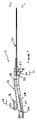
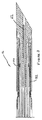
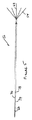
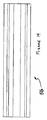
図1は本発明による多数のアンテナ(antenna )を備えた切除装置の平面図であり、カバーの図示を省略しかつその動作を説明するために一部を切り取って表示している。図2は図1の線2−2から見た正面図で、アンカー(anchor)システムを備えた本発明のプローブを表しており、アンカー及びアンテナ(スタイレット:針金)が展開した後の器具を表している。図3は本発明に従って作られたカテーテルの尖端の縦断面図である。図4はアンカーと切除用皮下チューブ(hypotube)が展開していない状態の本発明による平面図である。図5は7個の皮下チューブ切除電極と4個のアンカーが展開した状態の平面図である。図6は図5のカテーテル構造の斜視図である。図7は展開した皮下チューブとアンカーを示す縦断面図である。図8はトロカー(套管針)ポイントを皮下チューブを案内する撓み表面と共に示す平面図である。図9はトロカーポイントを皮下チューブを案内する撓み表面と共に示す斜視図である。図10はトロカーポイントを皮下チューブを案内する撓み表面と共に示す上面図である。 FIG. 1 is a plan view of an ablation apparatus provided with a plurality of antennas according to the present invention, in which a cover is not shown and a part thereof is cut out and displayed in order to explain its operation. FIG. 2 is a front view as seen from line 2-2 in FIG. 1, showing the probe of the present invention with an anchor system, with the instrument after the anchor and antenna (stylet: wire) have been deployed. Represents. FIG. 3 is a longitudinal cross-sectional view of the tip of a catheter made in accordance with the present invention. FIG. 4 is a plan view according to the present invention in a state where the anchor and the excision hypotube are not deployed. FIG. 5 is a plan view showing a state where seven subcutaneous tube excision electrodes and four anchors are deployed. FIG. 6 is a perspective view of the catheter structure of FIG. FIG. 7 is a longitudinal sectional view showing the developed hypodermic tube and anchor. FIG. 8 is a plan view showing a trocar point with a deflecting surface guiding a hypodermic tube. FIG. 9 is a perspective view showing a trocar point with a flexible surface guiding a hypodermic tube. FIG. 10 is a top view showing the trocar points with a deflecting surface guiding the hypodermic tube.
図11はトロカーポイントを皮下チューブを案内する撓み表面と共に示す底面図である。図12はトロカーポイントを皮下チューブを案内する撓み表面と共に示す背面図である。図13は多数の皮下チューブを把持するためのコアを示す斜視図である。図14は多数の皮下チューブを把持するためのコアを示す側平面図である。図15は多数の皮下チューブを把持するためのコアを示す背面図である。図16は多数の皮下チューブを把持するためのコアを示す側平面図である。図17は多数の皮下チューブを把持するためのコアを示す斜視図である。図18は多数の皮下チューブを把持するためのコアを示す背面図である。図19は多数の皮下チューブを把持するためのコアを示す斜視詳細図である。図20は皮下チューブの尖端が図19に示すようにコア内に保持されているときの多数の皮下チューブの尖端を示す斜視詳細図である。 FIG. 11 is a bottom view showing the trocar points with a deflecting surface guiding the hypodermic tube. FIG. 12 is a rear view showing the trocar points with a deflecting surface guiding the hypodermic tube. FIG. 13 is a perspective view showing a core for holding a large number of hypodermic tubes. FIG. 14 is a side plan view showing a core for holding a large number of hypodermic tubes. FIG. 15 is a rear view showing a core for holding a large number of hypodermic tubes. FIG. 16 is a side plan view showing a core for holding a large number of hypodermic tubes. FIG. 17 is a perspective view showing a core for holding a large number of hypodermic tubes. FIG. 18 is a rear view showing a core for holding a large number of hypodermic tubes. FIG. 19 is a detailed perspective view showing a core for holding a large number of hypodermic tubes. FIG. 20 is a detailed perspective view showing the tips of many hypodermic tubes when the tips of the hypodermic tubes are held in the core as shown in FIG.
図21は後方のアンカー部材を示す側平面図である。図22は後方のアンカー部材を示す斜視図である。図23は後方のアンカー部材を示す端面図である。図24はアンカーを撓ませるマンドレル部材を示す平面図である。図25はアンカーを撓ませるマンドレル部材を示す端面図である。図26はアンカーを撓ませるマンドレル部材を示す斜視図である。図27は皮下チューブ電極をアンカーから絶縁するための絶縁リングの斜視図である。図28は図27の線28−28に沿って皮下チューブ電極をアンカーから絶縁するための絶縁リングの縦断面図である。図29は皮下チューブ電極をアンカーから絶縁するための絶縁リングの側面図である。図30はアンカー押しチューブを示す斜視図である。 FIG. 21 is a side plan view showing the rear anchor member. FIG. 22 is a perspective view showing a rear anchor member. FIG. 23 is an end view showing the rear anchor member. FIG. 24 is a plan view showing a mandrel member that bends the anchor. FIG. 25 is an end view showing a mandrel member for bending the anchor. FIG. 26 is a perspective view showing a mandrel member for bending the anchor. FIG. 27 is a perspective view of an insulating ring for insulating the hypodermic tube electrode from the anchor. FIG. 28 is a longitudinal cross-sectional view of an insulating ring for insulating the hypodermic tube electrode from the anchor along line 28-28 of FIG. FIG. 29 is a side view of an insulating ring for insulating the hypodermic tube electrode from the anchor. FIG. 30 is a perspective view showing an anchor push tube.
図31は本発明によるアンカー押しチューブを示す側平面図である。図32は図1に類似して本発明による器具をアンカーと皮下チューブが展開した状態で示す一部を断面とした縦断面図である。図33はアンカーと皮下チューブ切除スタイレット(針金)を展開した状態で示す詳細斜視図である。図34は図33に類似して本発明の別の態様として皮下チューブとアンカーを完全に展開した状態で示す詳細斜視図である。 FIG. 31 is a side plan view showing an anchor push tube according to the present invention. FIG. 32 is a longitudinal sectional view, partially in section, showing a device according to the present invention in a state where the anchor and the hypodermic tube are deployed, similar to FIG. FIG. 33 is a detailed perspective view showing the anchor and the subcutaneous tube excision stylet (wire) in a developed state. FIG. 34 is a detailed perspective view showing the hypodermic tube and anchor in a fully expanded state as another embodiment of the present invention, similar to FIG.
図1には、本発明に従って作られた切除器具10が示されている。器具10はカテーテル部分12とハンドル部分14を備える。切除器具10は2つの係合するハンドル葉片のうち1つが図示を省略され、一部が断面として図示され、下記の説明に関連して内部の部品と動作を明らかにするように、図示されている。
FIG. 1 shows an
図1と図2において、本発明による切除器具10は、カテーテル部分12が組織、例えば無線周波数エネルギで処理されて切除されるべき組織内へと前進するのに適した完全後退位置で図示されている。この位置で、カテーテル12は単一の薄い滑らかなポイント付きの表面を提供し、この表面は損傷を最小にしながら健康な組織を突き刺すのにうまく適合する。同時に、カテーテルのポイントの鋭利さと比較的硬直した性質は、いくらか可撓性を有しながらも、ポイントに対する正確な操縦性と貫通する通路を制御することを可能にしている。子宮筋腫を処理する場合は、主として、かかる操縦性はカテーテル12を前進させながら子宮を手動操作することによって達成される。
1 and 2, an
ハンドル部分14は1対のアクチュエータ、すなわちスタイレットアクチュエータ16とアンカーリングアクチュエータ18とを有する。スタイレットアクチュエータ16は鋸歯状の表面20を有する。アンカーリングアクチュエータ18は1対の鋸歯状表面、すなわちアンカー引き戻し(後退)表面22とアンカー展開表面24とを有する。比較的大きな力の付与は壁26によって容易にでき、本発明による切除器具10を用いて実行される操作(手術)の各展開及び引き戻しのフェーズにおいて、この壁に対して外科医が親指やその他の指を押し付けることで力が付与できるようになっている。
The
スタイレットアクチュエータ16とアンカーリングアクチュエータ18はハンドル部分14内に支持されている。ハンドル部分14は、図2に示すように、左側ハウジング半葉片28と、この左側ハウジング半葉片28と対称形の右側ハウジング半葉片30とを包含している。
The
図3及び図4に示すように、本発明による切除器具は展開されていない状態で示される。この代わりに、図2,5,6,7に示すように、本発明による切除器具は、アンカー又は切除スタイレットが展開した状態で示されるか、あるいは図2,5,6,7に示すように、本発明による切除器具は、アンカー及びスタイレットの両方が完全に展開した状態で示される。 As shown in FIGS. 3 and 4, the ablation instrument according to the present invention is shown undeployed. Instead, as shown in FIGS. 2, 5, 6 and 7, the cutting instrument according to the present invention is shown with the anchor or cutting stylet deployed, or as shown in FIGS. In addition, the ablation instrument according to the present invention is shown with both the anchor and stylet fully deployed.
図7に示すように、切除器具10はトロカー(套管針)32内で終端し、トロカー32はポイント付きの尖端34を形成している。トロカー32はまた、後述するように、組織切除スタイレットが各種の方向に撓むための電極マンドレル(軸)としても機能する。トロカー32は図8〜図12に示されている。トロカー32は図11に明示されるように、底面36,側面38及び40で形成されるポイント付き尖端34(図7)を有する。表面36,38,40はトロカー32の末端部分42(図8)に集中している。トロカー32はまた中央溝44(図9)を有し、中央溝44はトロカー32の全長にわたって延伸し、トロカー32の中央軸線上に中心がある。
As shown in FIG. 7, the
図9に示すように、長手方向溝48の端部に複数の撓み表面46が配置されている。これらの表面46は可撓性の皮下チューブをゆっくりと屈曲させるように形成され、皮下チューブは子宮筋腫組織を切除する間に無線周波数(RF)エネルギで励起され、皮下チューブはカテーテル12から排出され、それに続いて組織が切除されるために通過する概ね真直な通路に従うようになっている。この撓みの際に、撓み表面46の活動は、絶縁性のあるテフロン(商品名)などの撓みリング52の内側の屈曲面50(図7)で補足されるようになっている。
As shown in FIG. 9, a plurality of flexure surfaces 46 are disposed at the end of the
本発明の特に好適な実施態様によれば、スタイレット54はステンレス鋼の代わりにニッケルチタン合金で作られる。この場合、撓み表面46の形状は、スタイレットのニッケルチタン合金材料に過重な歪みを生じさせることなく、撓みを最大化できるように形が作られる。特に、本発明の好適な実施態様によれば、表面46は歪みが8%以下になるように形成される。2〜8%の範囲の歪みは、約4%程度、例えば3.5〜4.5%の歪みで動作するとされる商業的な解決手段を満足させることができる。今日の技術では2%以下の歪みでは知覚可能な曲げを提供することができない。より高度なパフォーマンスは、撓み角度を維持できるように、歪みが6〜7%となる結果によって達成される。表面46を形成するには、歪みを8%に近づけ、例えば7.5%とすれば、切除容積を設計する際の撓みと可撓性を最大にすることができるが、皮下チューブスタイレット54の迅速な劣化を招く傾向がでてくる。しかしながら、もしも特定の処置が多数の切除を必要としない場合であれば、あるいは複数の廃棄可能なカテーテル10が許容される場合ならば、かかる装置は一定の環境の下で利点を発揮することができる。
According to a particularly preferred embodiment of the present invention, the
図7には多数の皮下チューブ54の撓みが示されている。皮下チューブ54は、鋼又はニッケルチタン合金で作られた可撓性の中空チューブである。皮下チューブ54は、本発明による切除装置10の全ての他の部品と同様に、特に指示がない場合は好適には、経済的理由及び/又は活動性の理由から、ステンレス鋼又は他の高い品質の鋼で作られる。チューブは内部容積56を形成し、その中にワイヤ式熱電対(thermocouple)が含まれ、熱電対は切除される組織の温度を測定する機能を達成し、時間に応じて切除操作(手術)の制御を容易にし、かつ切除された組織が壊死(necrotic)するのを確実にさせる。図7において、熱電対56は図示を容易にするために1個だけが図示してある。
FIG. 7 shows the deflection of a number of
皮下チューブ54は長手方向溝48内を摺動しながら移動することができる。図13〜図15に示すように、皮下チューブ54は切除電極として機能し、針状コア58上に搭載されている。針状コア58は複数の長手方向溝60を包含する。6個の皮下チューブ54の各々はそれぞれ対応する長手方向溝60内に搭載され、摩擦力あるいは接着剤を使用して溝60内に固定されている。7番目の皮下チューブ62は中心の軸線穴64内に搭載されている。図16〜図18には、針状コア58内にある皮下チューブ54と62の組立体が示されている。針状コア58内にある皮下チューブ54は、図19に最も明瞭に示されている。
The
図20に最も明瞭に示されるように、皮下チューブ54は、好適にはそれらのポイントである平坦表面65により方向付けられ、皮下チューブが展開する間に撓み表面46と摺動しながら協働するように方向付けられている。これは、皮下チューブ54のポイント付き尖端がカテーテル12の中心から半径方向に移動可能であることにより提供され、これは皮下チューブのポイント付き尖端が撓み表面46内に掘り進んでいくのを阻止するようになっている。
As shown most clearly in FIG. 20, hypotubes 54 are preferably oriented by their point,
可撓性の鋼電極押しチューブ66は針状コア58を包囲しかつ固定されており、針はコア58の中に搭載される。長手方向溝48内での皮下チューブ54の摺動運動は、電極押しチューブ66の運動によって達成される。矢印方向68(図7)への移動は皮下チューブ54,62の展開(延伸)を引き起こす。矢印方向70(図7)への移動は皮下チューブ54,62の後退(引き戻し)を引き起こす。
A flexible steel
図5及び図7において、可撓性の鋼電極マンドレルチューブ74が、電極押しチューブ66のまわりをかぶさるようにして配置されている。可撓性の鋼電極マンドレルチューブ74は、電極押しチューブ66がその内部を自由に摺動するのを許容している。これは、チューブの比較的大きな領域であるにもかかわらず達成される。なぜなら、チューブの向き合う表面は両方とも滑らかであり、かつ向き合う表面の間に小さな隙間があって摩擦を最小限にしているからである。かかる隙間は、従来技術でもなされるように、器具を水でフラッシング(清浄化)することを可能にしているのである。可撓性のプラスチック製筒状絶縁部材76は、電極マンドレルチューブ74のまわりをかぶさるように配置されている。
5 and 7, a flexible steel
絶縁部材76は、電気的無線周波数切除エネルギ(皮下チューブ54と62を励起するための押しチューブ66により搬送される)をアンカー押しチューブ78から隔離する。このことは、電気的切除エネルギがオプションとしてアンカー押しチューブ78に適用され、アンカー部材82上のアンカー80が独立して切除エネルギを適用し、電極スタイレット54と62によって切除されるのとは異なる容積を切除することを可能にする。図21〜図23にはアンカー部材82が示されている。アンカー80はレーザを用いて鋼管から切り出されて、鋼のアンカー部材82を形成する。各アンカー80は尖端84を有し、この尖端は半径方向外側に曲げられて、アンカー部材82が矢印70(図7)の方向へと移動するのに応答して、アンカーマンドレル86上へと撓むのを容易にする。
Insulating
図24〜図26にアンカーマンドレル86が示されている。アンカーマンドレル86は、図7と図26に最も明瞭に示されるように、複数の撓み表面88を有する。本発明の特に好適な実施態様では、アンカー部材82及びアンカー80は、ステンレス鋼の代わりにニッケルチタン合金で作られる。ニッケルチタン合金は、アンカー80とスタイレット54の両方に好適な材料である。
An
撓み表面88の形状は、アンカーのニッケルチタン合金材料に過剰な歪みを生じさせることなく、撓みを最大化するように形が作られる。さらに本発明の特に好適な実施態様では、表面88は歪みが8%以下となるように形成される。2〜8%の範囲の歪みは、約4%程度、例えば3.5〜4.5%、あるいは3%〜5%の歪みで動作するとされる商業的な解決手段を満足させることができる。より高度なパフォーマンスは、撓み角度を維持できるように、歪みが6〜7%となる結果によって達成される。表面88を形成するには、歪みを8%に近づけ、例えば7.5%とすれば、切除容積を設計する際の撓みと可撓性を最大にすることができるが、アンカー80の迅速な劣化を招く傾向がでてくる。しかしながら、もしも特定の処置が多数の切除を必要としない場合であれば、あるいは複数の廃棄可能なカテーテル10が許容される場合ならば、かかる装置は一定の環境の下で利点を発揮することができる。
The shape of the
カテーテル12の末端側端部の構造は、鋼製のアンカーカバー90で完成し、カバー90は、図27〜図29に示される絶縁リング52上に支持され、それらを包囲して固定される。撓む間に、アンカー80は、撓み表面88と鋼製アンカーカバー90の内側表面との間を通過する。
The structure of the distal end portion of the
図30と図31に示すように、アンカー押しチューブ78は、1対のキー92を包含し、キー92は文字『T』の形状をしている。キー92はアンカー部材82内のスロット94と係合する(噛み合う)。かくして、アンカー部材82とアンカー押しチューブ78は、アンカー80の展開及び後退の間、アンカー部材82とアンカー押しチューブ78が摺動運動するのに応答して、一体の部材として動作する。
As shown in FIGS. 30 and 31, the
カテーテル12の構造は外側チューブ96によって完成し、チューブ96はその一端でハンドル14に固定され、アンカー押しチューブ78上を摺動する筒状のスリップリング98に固定されている。
The structure of the
図1は、アンカーとスタイレットが展開する前の、アンカーアクチュエータ18とスタイレットアクチュエータ16の相対的位置を示している。
FIG. 1 shows the relative position of the
電極マンドレルチューブ74は、その中心側端部で、ハンドル14に固定されている。その末端側端部で、電極マンドレルチューブ74は、図3に示すように、トロカー32上の環状溝102(図8)内に例えば一定量のエポキシ系接着剤100を用いて、トロカー32に固定されている。変形例として、接着剤を使う代わりに、あるいはそれに追加して、電極マンドレルチューブ74にしわを形成させることもできる。スタイレットアクチュエータ16は電極押しチューブ66(図7)に固定されている。図1における矢印方向68への移動は、図5,6,7に符号32として示されているカテーテルの端部からスタイレットを出現させる。切除電極あるいはスタイレット54と62の完全な展開は、図33に最も明瞭に示されている。
The
アンカーアクチュエータ18はアンカー押しチューブ78に固定されている。その末端で、電極マンドレルチューブ74はアンカーマンドレル86に、例えば一定量のエポキシ系接着剤を用いて固定されている。従って、アンカーアクチュエータ18の図1における矢印符号70への移動は、図5,6,7に符号32として示されているカテーテルからアンカー80を出現させる。アンカー80の完全な展開は、図33に最も明瞭に示されている。
The
本発明によれば、本発明の切除装置10の制御は、1つ又は2つの電気スイッチ104,106(図1)で達成される。スイッチ106を操作することにより、例えばジョイスティック(joystick)のようにスイッチ106を軸線方向に動かして、ディスプレイ上にメニューを表示させることができる。スイッチ106を横方向に動かせば、メニューが切り換えられ、例えば切除時間を制御したり、切除温度を制御したり、その他のパラメータを切り換えることができる。選択されたパラメータの所定の値を選択するには、スイッチ106を横方向に動かしてディスプレイ上に各種の値が表示されるようにすることができる。外科医により、所望の値がスクリーン上に見えたならば、スイッチ104を押し下げることでその値が登録され、電気回路によって切除が指示され、本発明による切除装置10は選択されたパラメータに従って操作(手術)される。
In accordance with the present invention, control of the
RF(無線周波数)切除エネルギ、制御信号、及び温度測定信号は、コネクタ108により、本発明の切除装置10から制御ユニット/RFエネルギ源へと接続されている。本発明では、従来の切除システムに用いられていたような従来の無線周波数エネルギ源を、本発明による切除装置10と協働させることを考慮している。
RF (radio frequency) ablation energy, control signals, and temperature measurement signals are connected by connector 108 from the
本発明では、焼灼(cauterization )無線周波数エネルギもまた、トロカー32を患者から引き抜く際に、血液が失われるのを制御するために、適用することができる。焼灼を達成するために必要なRF信号の性質は、切除信号の性質とは異なる。これらの信号の両方は従来技術で定義されている。同様に、それらの生成も周知である。しかしながら、本発明では、従来の焼灼及び従来の切除信号もそれぞれ焼灼及び切除のために利用することができる。
In the present invention, cauterization radio frequency energy can also be applied to control the loss of blood when the
図34に、本発明の変形例として、カテーテル112が示されている。ここでは、アンカー180が切除電極154の末端に位置している。
FIG. 34 shows a
本発明の装置について、子宮筋腫を切除するための使用について図示してきたが、これは単なる例示であり、本発明の装置は多種多様な環境下で使用できることを理解されたい。同様に、本発明を図示した実施例について説明してきたが、開示された装置は当業者による各種の修正が可能であることも理解されたい。かかる修正は添付の請求範囲で定義される範囲において本発明の範囲に含まれるものである。 Although the device of the present invention has been illustrated for use to excise uterine fibroids, it should be understood that this is merely exemplary and that the device of the present invention can be used in a wide variety of environments. Similarly, while the present invention has been described with reference to illustrative embodiments, it should be understood that the disclosed apparatus can be variously modified by those skilled in the art. Such modifications are intended to be included within the scope of the present invention as defined by the appended claims.
10 切除器具 12 カテーテル
14 ハンドル部分 16 スタイレットアクチュエータ
18 アンカーリングアクチュエータ
32 トロカー 34 トロカーポイント
46 撓み表面 54 スタイレット
58 針状コア 62 皮下チューブ
80 アンカー 82 アンカー部材
DESCRIPTION OF
Claims (58)
(a)中心側端部と末端側端部とを有する細長いカニューレであって、当該カニューレ内に内部ルーメンとカニューレ軸線とを形成しているカニューレと、
(b)前記ルーメン内に包含される複数の導体であって、各導体が前記カニューレの中心側端部に近接する中心側端部と前記カニューレの末端側端部に近接する末端側端部とを有している導体と、
(c)複数の切除スタイレットであって各スタイレットが中心側端部と末端側端部とを有している切除スタイレットで、各スタイレットが当該スタイレットの各中心側端部で各導体の末端側端部に連結されており、当該スタイレットは可撓性の材料で作られ、前記導体はそれらに対応するスタイレットと共に軸線方向に移動可能になっている切除スタイレットと、
(d)前記カニューレの末端側端部に近接して形成されるトロカーポイントと、
(e)前記トロカーポイントと前記カニューレの中心側端部との間に配置される撓み表面であって、当該撓み表面は、前記スタイレットが前記カニューレの中心側端部から前記カニューレの末端側端部まで軸線方向に移動しかつ前記スタイレットの少なくともいくつかが前記カニューレの軸線に関して概ね真直な通路に沿って横方向に異なる方向で移動するのに対応して撓むことができるような形状と配置に作られており、前記通路が切除容積を形成している切除要素。 An ablation element,
(A) an elongate cannula having a central end and a distal end, the cannula forming an internal lumen and a cannula axis within the cannula;
(B) a plurality of conductors included in the lumen, each conductor having a central end adjacent to the central end of the cannula and a distal end adjacent to the distal end of the cannula; A conductor having
(C) a plurality of resection stylets, each stylet having a center end and a terminal end, each stylet at each center end of the stylet An ablation stylet connected to the distal end of the conductor, the stylet being made of a flexible material, the conductor being axially movable with its corresponding stylet;
(D) a trocar point formed proximate to the distal end of the cannula;
(E) a deflecting surface disposed between the trocar point and a central end of the cannula, wherein the deflecting surface is configured such that the stylet extends from the central end of the cannula to the distal end of the cannula A shape that can move axially to a portion and bendable in response to at least some of the stylets moving laterally in different directions along a generally straight passage with respect to the axis of the cannula. An ablation element made in arrangement, wherein the passage forms an ablation volume.
(g)前記ルーメン内に配置されかつ前記アンカーに連結されて前記アンカーを前記内部位置と前記アンカー位置との間で駆動する駆動部材とを有する請求項1記載の切除要素。 Further, (f) the anchor is movable between an internal position set in the trocar surface and an anchor position extending laterally from the trocar surface through a point outside the lumen. Mounted anchor,
The ablation element according to claim 1, further comprising: a drive member disposed within the lumen and coupled to the anchor to drive the anchor between the internal position and the anchor position.
(a)中心側端部と末端側端部とを有する細長いカニューレであって、当該カニューレ内に内部ルーメンとカニューレ軸線とを形成しているカニューレと、
(b)前記ルーメン内に包含される複数の導体であって、各導体が前記カニューレの中心側端部に近接する中心側端部と前記カニューレの末端側端部に近接する末端側端部とを有している導体と、
(c)複数の切除スタイレットであって各切除スタイレットが中心側端部と末端側端部とを有している切除スタイレットで、各切除スタイレットが当該切除スタイレットの各中心側端部で各導体の末端側端部に連結されており、当該切除スタイレットは可撓性の材料で作られ、前記導体はそれらに対応する切除スタイレットと共に軸線方向に移動可能になっている切除スタイレットと、
(d)前記カニューレの末端側端部に近接して形成されるフロントエンドと、
(e)前記フロントエンドと前記カニューレの中心側端部との間に配置される撓み表面であって、当該撓み表面は、前記切除スタイレットが前記カニューレの中心側端部から前記カニューレの末端側端部まで軸線方向に移動しかつ前記切除スタイレットの少なくともいくつかが前記カニューレの軸線に関して概ね真直な通路に沿って横方向に異なる方向で移動するのに対応して撓むことができるような形状と配置に作られており、前記通路が切除容積を形成している切除要素。 An ablation element,
(A) an elongate cannula having a central end and a distal end, the cannula forming an internal lumen and a cannula axis within the cannula;
(B) a plurality of conductors included in the lumen, each conductor having a central end adjacent to the central end of the cannula and a distal end adjacent to the distal end of the cannula; A conductor having
(C) A resection stylet that is a plurality of resection stylets, each resection stylet having a central end and a distal end, each resection stylet corresponding to each central end of the resection stylet Are connected to the distal end of each conductor, the cutting stylet being made of a flexible material, the conductor being axially movable with their corresponding cutting stylet Stylet and
(D) a front end formed proximate to the distal end of the cannula;
(E) a flexure surface disposed between the front end and the central end of the cannula, the flexure surface being configured so that the ablation stylet is distal to the cannula from the central end of the cannula. Move axially to the end and bendable so that at least some of the ablation stylets move in different directions laterally along a generally straight path with respect to the axis of the cannula An ablation element made in shape and arrangement, wherein the passage forms an ablation volume.
(a)中心側端部と末端側端部とを有する細長いカニューレであって、当該カニューレ内に内部ルーメンとカニューレ軸線とを形成しているカニューレと、
(b)前記ルーメン内に包含される複数の導体であって、各導体が前記カニューレの中心側端部に近接する中心側端部と前記カニューレの末端側端部に近接する末端側端部とを有している導体と、
(c)複数の切除スタイレットであって各切除スタイレットが中心側端部と末端側端部とを有している切除スタイレットで、各切除スタイレットが当該切除スタイレットの各中心側端部で各導体の末端側端部に連結されており、当該切除スタイレットは可撓性の材料で作られ、前記導体はそれらに対応する切除スタイレットと共に軸線方向に移動可能になっている切除スタイレットと、
(d)前記カニューレの末端側端部に近接して形成されるフロントエンドと、
(f)アンカーであって、前記トロカー表面内に設定された内部位置と前記トロカー表面から横方向に延伸するアンカー位置との間を、前記ルーメンの外部のポイントを通じて、移動可能とするように搭載されたアンカーと、
(g)前記ルーメン内に配置されかつ前記アンカーに連結されて前記アンカーを前記内部位置と前記アンカー位置との間で駆動する駆動部材とを備え、
前記アンカーは少なくとも2つのポイント付き部材を有し、これらポイント付き部材はベクター成分を有する方向に移動するように搭載され、前記ベクター成分は前記軸線あるいは前記カニューレから遠ざかる方向へと延伸し、かつ相互に遠ざかる方向方向に延伸している切除要素。 An ablation element,
(A) an elongate cannula having a central end and a distal end, the cannula forming an internal lumen and a cannula axis within the cannula;
(B) a plurality of conductors included in the lumen, each conductor having a central end adjacent to the central end of the cannula and a distal end adjacent to the distal end of the cannula; A conductor having
(C) A resection stylet that is a plurality of resection stylets, each resection stylet having a central end and a distal end, each resection stylet corresponding to each central end of the resection stylet Are connected to the distal end of each conductor, the cutting stylet being made of a flexible material, the conductor being axially movable with their corresponding cutting stylet Stylet and
(D) a front end formed proximate to the distal end of the cannula;
(F) An anchor mounted so as to be movable between an internal position set in the trocar surface and an anchor position extending laterally from the trocar surface through a point outside the lumen. Anchors,
(G) a drive member disposed within the lumen and coupled to the anchor to drive the anchor between the internal position and the anchor position;
The anchor has at least two pointed members that are mounted to move in a direction having a vector component, the vector component extending in a direction away from the axis or the cannula and A cutting element extending in a direction away from the.
(a)中心側端部と末端側端部とを有する細長いカニューレであって、当該カニューレ内に内部ルーメンとカニューレ軸線とを形成しているカニューレと、
(b)複数の切除スタイレットであって、各切除スタイレットが中心側端部と末端側端部を有し、当該切除スタイレットは前記切除スタイレットの前記末端側端部が自由に撓むことができるような形状で相互に連結されており、当該切除スタイレットは単一の切除スタイレット列を形成し、前記単一の切除スタイレット列は前記細長いカニューレに関して摺動運動できるように搭載され、当該切除スタイレットは可撓性材料で作られている切除スタイレットと、
(c)切除スタイレット摺動部材であって、当該切除スタイレット摺動部材は前記カニューレの中心側端部に近接する中心側端部と前記カニューレの末端側端部に近接して位置決め可能な末端側端部と有し、当該切除スタイレット摺動部材は前記カニューレに対して摺動可能に搭載され、当該切除スタイレット摺動部材はエネルギの有効な導体であるような切除スタイレット摺動部材と、
(d)トロカーポイントを形成するトロカーポイント組立体であって、当該トロカーポイント組立体は前記カニューレの前記末端側端部に近接して前記カニューレに固定されるようになっているようなトロカーポイント組立体とを備え、
前記トロカーポイント組立体は、
(i)前記トロカーの摺動運動を受け入れかつ案内するための複数のトラックと、
(ii)前記トロカーポイントと前記カニューレの前記中心側端部との間に位置する複数のスタイレット撓み表面とを備え、前記スタイレット撓み表面は、前記スタイレットが前記カニューレの前記中心側端部から前記カニューレの前記末端側端部の方向へと軸線方向に移動しかつ少なくとも1つのスタイレットが前記カニューレの軸線から離れて概ね真直な通路に沿った異なる方向へと移動するのに応答して撓むような形状と位置に設けられており、前記真直な通路が切除容積を形成している切除要素。 An ablation element,
(A) an elongate cannula having a central end and a distal end, the cannula forming an internal lumen and a cannula axis within the cannula;
(B) A plurality of ablation stylets, each ablation stylet having a central end and a distal end, and the ablation stylet is free to bend at the distal end of the ablation stylet. Connected to each other in a shape such that the ablation stylets form a single ablation stylet row, the ablation stylet row mounted for sliding movement with respect to the elongate cannula The ablation stylet is made of a flexible material; and
(C) A cutting stylet sliding member, wherein the cutting stylet sliding member can be positioned in the vicinity of the central end of the cannula and the distal end of the cannula. An ablation stylet slide having a distal end and the ablation stylet sliding member is slidably mounted relative to the cannula, the ablation stylet sliding member being an energy efficient conductor Members,
(D) a trocar point assembly forming a trocar point, wherein the trocar point assembly is adapted to be secured to the cannula proximate to the distal end of the cannula With three-dimensional
The trocar point assembly is
(I) a plurality of tracks for receiving and guiding a sliding movement of the trocar;
(Ii) a plurality of stylet flexure surfaces located between the trocar point and the central end of the cannula, wherein the stylet flexure surface is such that the stylet is the central end of the cannula. In response to moving axially in the direction of the distal end of the cannula and at least one stylet in a different direction along a generally straight path away from the axis of the cannula. An ablation element provided in a deflectable shape and position, wherein the straight passage forms an ablation volume.
(f)アンカー摺動部材であって、当該アンカー摺動部材が前記カニューレに対して摺動運動できるように搭載され、当該アンカー摺動部材はエネルギを有効に伝達するアンカー摺動部材とを備え、
さらに前記トロカーポイント組立体が、
(iii )前記トロカーポイントと前記カニューレの前記中心側端部との間に位置するアンカー撓み表面を有し、当該アンカー撓み表面は前記アンカーの軸線方向運動に応答して撓むような形状と位置に設けられ、前記アンカーは前記カニューレの軸線から離れるあご状のかえりの形状をしている請求項31記載の切除要素。 And (e) an anchor, the anchor having a central end and a distal end, the anchor having a freely deflectable end, the anchor being a single anchor row The single anchor row is mounted for sliding movement relative to the elongated cannula, the anchor being made of a flexible material;
(F) An anchor sliding member that is mounted so that the anchor sliding member can slide relative to the cannula, and the anchor sliding member includes an anchor sliding member that effectively transmits energy. ,
Further, the trocar point assembly is
(Iii) an anchor flexure surface located between the trocar point and the central end of the cannula, wherein the anchor flexure surface is shaped and positioned to flex in response to axial movement of the anchor; 32. An ablation element according to claim 31, wherein the ablation element is provided and the anchor is in the form of a jawed burr that is spaced from the axis of the cannula.
(a)中心側端部と末端側端部とを有する細長いカニューレであって、当該カニューレ内に内部ルーメンとカニューレ軸線とを形成しているカニューレと、
(b)複数の切除スタイレットであって、各切除スタイレットが中心側端部と末端側端部を有し、当該切除スタイレットは前記切除スタイレットの前記末端側端部が自由に撓むことができるような形状で相互に連結されており、当該切除スタイレットは単一の切除スタイレット列を形成し、前記単一の切除スタイレット列は前記カニューレ内に位置決めされ、前記単一の切除スタイレット列は前記細長いカニューレに関して摺動運動できるように搭載され、当該切除スタイレットは可撓性材料で作られている切除スタイレットと、
(c)切除スタイレット摺動部材であって、当該切除スタイレット摺動部材は前記カニューレの中心側端部に近接する中心側端部と前記カニューレの末端側端部に近接して位置決め可能な末端側端部と有し、当該切除スタイレット摺動部材は前記ルーメン内で前記カニューレに対して摺動可能に搭載され、当該切除スタイレット摺動部材は前記単一の切除スタイレット列に固定され、当該切除スタイレット摺動部材はエネルギの導体であるような切除スタイレット摺動部材と、
(d)トロカーポイントを形成するトロカーポイント組立体であって、当該トロカーポイント組立体は前記カニューレの前記末端側端部に近接して前記カニューレに固定されるようになっているようなトロカーポイント組立体とを備え、
前記トロカーポイント組立体は、前記トロカーポイントと前記カニューレの前記中心側端部との間に位置する複数のスタイレット撓み表面を有し、前記スタイレット撓み表面は、各スタイレットの撓み領域で前記スタイレットの末端側端部を撓ませるような形状と位置に設けられ、前記スタイレットが前記カニューレの前記中心側端部から前記カニューレの前記末端側端部の方向へと軸線方向に移動しかつ少なくとも2つのスタイレットが前記カニューレの軸線から離れて、前記2つの撓んだスタイレットの各々が概ね真直な通路に沿った異なる方向へと移動するのに応答して撓むような形状と位置に設けられており、前記真直な通路が切除容積を形成している切除要素。 An ablation element,
(A) an elongate cannula having a central end and a distal end, the cannula forming an internal lumen and a cannula axis within the cannula;
(B) A plurality of ablation stylets, each ablation stylet having a central end and a distal end, and the ablation stylet is free to bend at the distal end of the ablation stylet. Connected to each other in a shape such that the ablation stylets form a single ablation stylet row, the single ablation stylet row positioned within the cannula, An ablation stylet is mounted for sliding movement with respect to the elongated cannula, the ablation stylet being made of a flexible material;
(C) A cutting stylet sliding member, wherein the cutting stylet sliding member can be positioned in the vicinity of the central end of the cannula and the distal end of the cannula. The cutting stylet sliding member is slidably mounted with respect to the cannula within the lumen, and the cutting stylet sliding member is fixed to the single cutting stylet row. The ablation stylet sliding member is a conductor of energy, and
(D) a trocar point assembly forming a trocar point, wherein the trocar point assembly is adapted to be secured to the cannula proximate to the distal end of the cannula With three-dimensional
The trocar point assembly has a plurality of stylet deflecting surfaces located between the trocar point and the central end of the cannula, the stylet deflecting surfaces being at the stylet deflection region. Shaped and positioned to deflect the distal end of the stylet, the stylet moving axially from the central end of the cannula to the distal end of the cannula; In a shape and position such that at least two stylets move away from the cannula axis and each of the two deflected stylets flex in response to moving in different directions along a generally straight path. An ablation element provided, wherein the straight passage forms an ablation volume.
(f)アンカー摺動部材であって、当該アンカー摺動部材が前記カニューレの前記中心側端部に近接する中心側端部と前記カニューレの前記末端側端部に近接する末端側端部とを有し、当該アンカー摺動部材が前記カニューレに対して摺動運動できるように前記ルーメン内に搭載され、当該アンカー摺動部材は前記アンカーに固定されているアンカー摺動部材と、
(g)前記トロカーポイントと前記カニューレの前記中心側端部との間に位置するアンカー撓み表面とを有し、当該アンカー撓み表面は前記アンカーの軸線方向運動に応答して撓むような形状と位置に設けられ、前記アンカーは前記カニューレの軸線から離れるあご状のかえりの形状をしている請求項48記載の切除要素。 And (e) an anchor, the anchor having a central end and a distal end, the anchor having a freely deflectable end, the anchor being a single anchor row The single anchor row is mounted for sliding movement relative to the elongated cannula, the anchor being made of a flexible material;
(F) An anchor sliding member, wherein the anchor sliding member has a central end portion close to the central end portion of the cannula and a distal end portion close to the distal end portion of the cannula. An anchor sliding member mounted in the lumen so that the anchor sliding member can slide relative to the cannula, the anchor sliding member being fixed to the anchor;
(G) having an anchor flexure surface located between the trocar point and the central end of the cannula, the anchor flexure surface being shaped and positioned to flex in response to axial movement of the anchor 49. An ablation element according to claim 48, wherein the anchor is in the form of a jawed burr that is spaced from the axis of the cannula.
(f)前記細長いカニューレに対して摺動運動できるように搭載された環状部材であって、前記アンカーが前記環状部分と一体であり、前記アンカーが単一のアンカー列を形成し、前記アンカーが可撓性材料で作られている環状部材と、
(g)前記環状部材と一体のアンカー係合部材と、
(h)前記アンカー係合部材と一体のアンカー結合部材と、
(i)アンカー摺動部材であって、当該アンカー摺動部材は前記カニューレの前記中心側端部に近接する中心側端部と前記カニューレの前記末端側端部に近接して位置決め可能な末端側端部とを有し、当該アンカー摺動部材は前記カニューレに対して摺動運動できるように前記ルーメン内に搭載され、当該アンカー摺動部材は前記アンカー結合部材に固定されるようになっているアンカー摺動部材と、
(j)前記トロカーポイントと前記カニューレの前記中心側端部との間に位置決めされるアンカー撓み表面とを備え、
前記アンカー撓み表面は前記アンカーの軸線方向運動に応答して撓むような形状と位置に設けられ、前記アンカーは前記カニューレの軸線から離れて前記カニューレの前記中心側端部に向かうあご状のかえりの形状をしている請求項48記載の切除要素。 And (e) a plurality of anchors, the anchor having a center side end and a terminal end, and the anchor having an end that can be freely bent;
(F) an annular member mounted for sliding movement relative to the elongated cannula, wherein the anchor is integral with the annular portion, the anchor forms a single anchor row, An annular member made of a flexible material;
(G) an anchor engaging member integral with the annular member;
(H) an anchor coupling member integral with the anchor engaging member;
(I) An anchor sliding member, wherein the anchor sliding member is positioned at a central end near the central end of the cannula and a distal end positionable near the distal end of the cannula. The anchor sliding member is mounted in the lumen so as to be slidable relative to the cannula, and the anchor sliding member is fixed to the anchor coupling member. An anchor sliding member;
(J) an anchor flexure surface positioned between the trocar point and the central end of the cannula,
The anchor flexure surface is provided in a shape and position such that the anchor deflects in response to axial movement of the anchor, and the anchor is spaced from the cannula axis toward the central end of the cannula. 49. The ablation element of claim 48, wherein the ablation element is shaped.
Applications Claiming Priority (3)
| Application Number | Priority Date | Filing Date | Title |
|---|---|---|---|
| US11/173,928 US8080009B2 (en) | 2005-07-01 | 2005-07-01 | Radio frequency ablation device for the destruction of tissue masses |
| US11/429,921 US8512333B2 (en) | 2005-07-01 | 2006-05-08 | Anchored RF ablation device for the destruction of tissue masses |
| PCT/US2006/025975 WO2007005830A2 (en) | 2005-07-01 | 2006-06-30 | Anchored rf ablation device for the destruction of tissue masses |
Publications (2)
| Publication Number | Publication Date |
|---|---|
| JP2009504201A true JP2009504201A (en) | 2009-02-05 |
| JP2009504201A5 JP2009504201A5 (en) | 2009-08-20 |
Family
ID=37605129
Family Applications (1)
| Application Number | Title | Priority Date | Filing Date |
|---|---|---|---|
| JP2008520328A Pending JP2009504201A (en) | 2005-07-01 | 2006-06-30 | Anchored radio frequency ablation device for destroying tissue swelling |
Country Status (6)
| Country | Link |
|---|---|
| US (3) | US8512333B2 (en) |
| EP (1) | EP1898822B1 (en) |
| JP (1) | JP2009504201A (en) |
| AU (1) | AU2006265624B2 (en) |
| CA (1) | CA2614328C (en) |
| WO (1) | WO2007005830A2 (en) |
Cited By (6)
| Publication number | Priority date | Publication date | Assignee | Title |
|---|---|---|---|---|
| JP2012519037A (en) * | 2009-02-27 | 2012-08-23 | ガイネソニックス, インコーポレイテッド | Needle and tooth deployment mechanism |
| KR101176986B1 (en) | 2010-04-05 | 2012-08-27 | 유상영 | intra-vaginal insertion tool for laparoscopic-assisted radical hystectomy |
| JP2014508558A (en) * | 2010-12-21 | 2014-04-10 | ユニバーシティ・オブ・ユタ・リサーチ・ファウンデイション | Assembly and use of optically guided medical tubes and control units |
| JP2016064152A (en) * | 2010-05-21 | 2016-04-28 | ニンバス・コンセプツ・エルエルシー | Tissue ablation system and method |
| US10736688B2 (en) | 2009-11-05 | 2020-08-11 | Stratus Medical, LLC | Methods and systems for spinal radio frequency neurotomy |
| JP2021511097A (en) * | 2017-12-15 | 2021-05-06 | シー・アール・バード・インコーポレーテッドC R Bard Incorporated | Impedance measurement probe and biopsy device |
Families Citing this family (42)
| Publication number | Priority date | Publication date | Assignee | Title |
|---|---|---|---|---|
| US7270656B2 (en) | 2003-11-07 | 2007-09-18 | Visualase, Inc. | Cooled laser fiber for improved thermal therapy |
| US7918795B2 (en) | 2005-02-02 | 2011-04-05 | Gynesonics, Inc. | Method and device for uterine fibroid treatment |
| US8512330B2 (en) | 2005-07-01 | 2013-08-20 | Halt Medical Inc. | Ablation method |
| US8080009B2 (en) | 2005-07-01 | 2011-12-20 | Halt Medical Inc. | Radio frequency ablation device for the destruction of tissue masses |
| US10058342B2 (en) | 2006-01-12 | 2018-08-28 | Gynesonics, Inc. | Devices and methods for treatment of tissue |
| US7874986B2 (en) * | 2006-04-20 | 2011-01-25 | Gynesonics, Inc. | Methods and devices for visualization and ablation of tissue |
| US11259825B2 (en) | 2006-01-12 | 2022-03-01 | Gynesonics, Inc. | Devices and methods for treatment of tissue |
| US20070161905A1 (en) * | 2006-01-12 | 2007-07-12 | Gynesonics, Inc. | Intrauterine ultrasound and method for use |
| US7815571B2 (en) * | 2006-04-20 | 2010-10-19 | Gynesonics, Inc. | Rigid delivery systems having inclined ultrasound and needle |
| US9357977B2 (en) | 2006-01-12 | 2016-06-07 | Gynesonics, Inc. | Interventional deployment and imaging system |
| US10595819B2 (en) | 2006-04-20 | 2020-03-24 | Gynesonics, Inc. | Ablation device with articulated imaging transducer |
| US20100056926A1 (en) * | 2008-08-26 | 2010-03-04 | Gynesonics, Inc. | Ablation device with articulated imaging transducer |
| US8206300B2 (en) | 2008-08-26 | 2012-06-26 | Gynesonics, Inc. | Ablation device with articulated imaging transducer |
| US9403029B2 (en) | 2007-07-18 | 2016-08-02 | Visualase, Inc. | Systems and methods for thermal therapy |
| US8088072B2 (en) | 2007-10-12 | 2012-01-03 | Gynesonics, Inc. | Methods and systems for controlled deployment of needles in tissue |
| US8241276B2 (en) * | 2007-11-14 | 2012-08-14 | Halt Medical Inc. | RF ablation device with jam-preventing electrical coupling member |
| US8251991B2 (en) * | 2007-11-14 | 2012-08-28 | Halt Medical Inc. | Anchored RF ablation device for the destruction of tissue masses |
| US9032806B2 (en) * | 2008-02-25 | 2015-05-19 | Atrial Systems, Llc | Force assessment device and method for lead extraction |
| WO2009124301A1 (en) * | 2008-04-03 | 2009-10-08 | Visualase, Inc. | Systems and methods for thermal therapy |
| US20090287081A1 (en) * | 2008-04-29 | 2009-11-19 | Gynesonics , Inc | Submucosal fibroid ablation for the treatment of menorrhagia |
| EP2210567B1 (en) * | 2009-01-26 | 2013-07-31 | Lina Medical ApS | A bipolar electrosurgical instrument |
| US20100298761A1 (en) * | 2009-05-20 | 2010-11-25 | Sonion A/S | Electroporation device with improved tip and electrode support |
| AU2015261694C1 (en) * | 2009-11-05 | 2021-11-25 | Stratus Medical, LLC | Methods and systems for spinal radio frequency neurotomy |
| WO2011081897A1 (en) * | 2009-12-15 | 2011-07-07 | Alcon Research, Ltd. | High-intensity pulsed electric field vitrectomy apparatus |
| CN105167841A (en) * | 2010-05-21 | 2015-12-23 | 光轮概念公司 | Systems and methods for tissue ablation |
| US8992427B2 (en) | 2012-09-07 | 2015-03-31 | Gynesonics, Inc. | Methods and systems for controlled deployment of needle structures in tissue |
| EP3673877A1 (en) | 2013-10-18 | 2020-07-01 | Ziva Medical, Inc. | Systems for the treatment of polycystic ovary syndrome |
| EP3701899B1 (en) | 2015-03-31 | 2022-05-18 | St. Jude Medical, Cardiology Division, Inc. | Devices for delivering pulsed rf energy during catheter ablation |
| WO2016161011A1 (en) | 2015-03-31 | 2016-10-06 | Ziva Medical, Inc. | Methods and systems for the manipulation of ovarian tissues |
| CN108024822B (en) | 2015-06-17 | 2021-07-02 | 史赛克欧洲控股I有限责任公司 | Surgical instrument with ultrasonic tip for fibrous tissue removal |
| US11172821B2 (en) | 2016-04-28 | 2021-11-16 | Medtronic Navigation, Inc. | Navigation and local thermometry |
| JP6718557B2 (en) | 2016-10-04 | 2020-07-08 | セント・ジュード・メディカル,カーディオロジー・ディヴィジョン,インコーポレイテッド | Ablation catheter tip |
| JP7237829B2 (en) | 2016-11-11 | 2023-03-13 | ガイネソニックス, インコーポレイテッド | Dynamic interaction of tissue controlled treatment with tissue and/or treatment data and their comparison |
| WO2018089923A1 (en) | 2016-11-14 | 2018-05-17 | Gynesonics, Inc. | Methods and systems for real-time planning and monitoring of ablation needle deployment in tissue |
| JP2020518385A (en) | 2017-05-04 | 2020-06-25 | ガイネソニックス, インコーポレイテッド | A method for monitoring ablation progression using Doppler ultrasound |
| JP7291697B2 (en) | 2017-11-09 | 2023-06-15 | アセッサー・ヘルス・インコーポレーテッド | A system for controlling ablation therapy and visualization |
| CN114025693A (en) | 2019-01-25 | 2022-02-08 | 阿布拉护理法国公司 | Systems and methods for applying energy to ovarian tissue |
| WO2021086817A1 (en) * | 2019-10-28 | 2021-05-06 | Boston Scientific Neuromodulation Corporation | Rf electrode cannula |
| WO2022141769A1 (en) * | 2020-12-31 | 2022-07-07 | 杭州堃博生物科技有限公司 | Radio-frequency ablation catheter and radio-frequency ablation system |
| CN110960314B (en) * | 2019-12-31 | 2021-06-15 | 杭州堃博生物科技有限公司 | Detection mechanism, radiofrequency ablation catheter and radiofrequency ablation system |
| US11672595B1 (en) | 2022-06-15 | 2023-06-13 | Corveus Medical, Inc. | Systems and methods for interrupting nerve activity to treat a medical condition |
| CN117159128B (en) * | 2023-11-03 | 2024-01-30 | 浙江伽奈维医疗科技有限公司 | Ablation device and ablation electrode for steep pulse ablation and/or radio frequency ablation |
Citations (3)
| Publication number | Priority date | Publication date | Assignee | Title |
|---|---|---|---|---|
| WO1995010253A1 (en) * | 1993-10-15 | 1995-04-20 | Urologix, Inc. | Piercing thermal therapy catheter |
| JP2001231790A (en) * | 1995-08-15 | 2001-08-28 | Rita Medical Systems Inc | Ablation device |
| WO2004037102A1 (en) * | 2002-10-22 | 2004-05-06 | Iginio Longo | Interstitial microwave antenna with lateral effect for tissues hyperthermia in minimal invasive surgery |
Family Cites Families (133)
| Publication number | Priority date | Publication date | Assignee | Title |
|---|---|---|---|---|
| US35330A (en) | 1862-05-20 | Improved foot corn-planter | ||
| DE2124684A1 (en) * | 1971-05-18 | 1972-11-30 | Stadelmann W | Puncture electrode |
| US3991770A (en) | 1974-01-24 | 1976-11-16 | Leveen Harry H | Method for treating benign and malignant tumors utilizing radio frequency, electromagnetic radiation |
| US4303636A (en) | 1974-08-20 | 1981-12-01 | Gordon Robert T | Cancer treatment |
| US4016886A (en) | 1974-11-26 | 1977-04-12 | The United States Of America As Represented By The United States Energy Research And Development Administration | Method for localizing heating in tumor tissue |
| US4230129A (en) | 1975-07-11 | 1980-10-28 | Leveen Harry H | Radio frequency, electromagnetic radiation device having orbital mount |
| US4119102A (en) | 1975-07-11 | 1978-10-10 | Leveen Harry H | Radio frequency treatment of tumors while inducing hypotension |
| US4074718A (en) | 1976-03-17 | 1978-02-21 | Valleylab, Inc. | Electrosurgical instrument |
| US4080959A (en) | 1976-06-18 | 1978-03-28 | Leveen Robert F | Method for detection of tumors of the breast |
| US4095602A (en) | 1976-09-27 | 1978-06-20 | Leveen Harry H | Multi-portal radiofrequency generator |
| US4140130A (en) | 1977-05-31 | 1979-02-20 | Storm Iii Frederick K | Electrode structure for radio frequency localized heating of tumor bearing tissue |
| US4154246A (en) | 1977-07-25 | 1979-05-15 | Leveen Harry H | Field intensification in radio frequency thermotherapy |
| US4346715A (en) | 1978-07-12 | 1982-08-31 | The United States Of America As Represented By The Administrator Of The National Aeronautics And Space Administration | Hyperthermia heating apparatus |
| US4285346A (en) | 1979-03-14 | 1981-08-25 | Harry V. LeVeen | Electrode system |
| US4290435A (en) | 1979-09-07 | 1981-09-22 | Thermatime A.G. | Internally cooled electrode for hyperthermal treatment and method of use |
| US4375220A (en) | 1980-05-09 | 1983-03-01 | Matvias Fredrick M | Microwave applicator with cooling mechanism for intracavitary treatment of cancer |
| US4565200A (en) | 1980-09-24 | 1986-01-21 | Cosman Eric R | Universal lesion and recording electrode system |
| US5385544A (en) | 1992-08-12 | 1995-01-31 | Vidamed, Inc. | BPH ablation method and apparatus |
| US5435805A (en) | 1992-08-12 | 1995-07-25 | Vidamed, Inc. | Medical probe device with optical viewing capability |
| US5542915A (en) | 1992-08-12 | 1996-08-06 | Vidamed, Inc. | Thermal mapping catheter with ultrasound probe |
| US5370675A (en) * | 1992-08-12 | 1994-12-06 | Vidamed, Inc. | Medical probe device and method |
| US5421819A (en) | 1992-08-12 | 1995-06-06 | Vidamed, Inc. | Medical probe device |
| CA1244889A (en) | 1983-01-24 | 1988-11-15 | Kureha Chemical Ind Co Ltd | Device for hyperthermia |
| US4545368A (en) | 1983-04-13 | 1985-10-08 | Rand Robert W | Induction heating method for use in causing necrosis of neoplasm |
| JPS6055966A (en) | 1983-09-05 | 1985-04-01 | オリンパス光学工業株式会社 | Medical electrode apparatus |
| US4709701A (en) | 1986-04-15 | 1987-12-01 | Medical Research & Development Associates | Apparatus for medical treatment by hyperthermia |
| US4962761A (en) | 1987-02-24 | 1990-10-16 | Golden Theodore A | Thermal bandage |
| US5003991A (en) | 1987-03-31 | 1991-04-02 | Olympus Optical Co., Ltd. | Hyperthermia apparatus |
| US4823791A (en) | 1987-05-08 | 1989-04-25 | Circon Acmi Division Of Circon Corporation | Electrosurgical probe apparatus |
| US4773864A (en) | 1987-08-31 | 1988-09-27 | Holt Byron B | Apparatus for enhancing surgical skills |
| US5151101A (en) | 1988-06-02 | 1992-09-29 | Circon Corporation | System for disconnectably mounting an endoscope sheath with an endoscope tool |
| US4955884A (en) | 1988-06-02 | 1990-09-11 | Circon Corporation | System for reducing drag on the movement of an electrode in a resectoscope |
| US4881543A (en) | 1988-06-28 | 1989-11-21 | Massachusetts Institute Of Technology | Combined microwave heating and surface cooling of the cornea |
| FR2639238B1 (en) | 1988-11-21 | 1991-02-22 | Technomed Int Sa | APPARATUS FOR SURGICAL TREATMENT OF TISSUES BY HYPERTHERMIA, PREFERABLY THE PROSTATE, COMPRISING MEANS OF THERMAL PROTECTION COMPRISING PREFERABLY RADIOREFLECTIVE SCREEN MEANS |
| US5010897A (en) | 1989-04-26 | 1991-04-30 | Leveen Harry H | Apparatus for deep heating of cancer |
| US5057104A (en) | 1989-05-30 | 1991-10-15 | Cyrus Chess | Method and apparatus for treating cutaneous vascular lesions |
| US5099756A (en) | 1989-06-01 | 1992-03-31 | Harry H. Leveen | Radio frequency thermotherapy |
| US5007908A (en) | 1989-09-29 | 1991-04-16 | Everest Medical Corporation | Electrosurgical instrument having needle cutting electrode and spot-coag electrode |
| US5273535A (en) | 1991-11-08 | 1993-12-28 | Ep Technologies, Inc. | Catheter with electrode tip having asymmetric left and right curve configurations |
| US5190541A (en) | 1990-10-17 | 1993-03-02 | Boston Scientific Corporation | Surgical instrument and method |
| US5409453A (en) | 1992-08-12 | 1995-04-25 | Vidamed, Inc. | Steerable medical probe with stylets |
| WO1992020290A1 (en) | 1991-05-17 | 1992-11-26 | Innerdyne Medical, Inc. | Method and device for thermal ablation |
| US5542928A (en) | 1991-05-17 | 1996-08-06 | Innerdyne, Inc. | Method and device for thermal ablation having improved heat transfer |
| EP0588864A4 (en) | 1991-05-24 | 1996-01-10 | Ep Technologies | Combination monophasic action potential/ablation catheter and high-performance filter system |
| US5190517A (en) | 1991-06-06 | 1993-03-02 | Valleylab Inc. | Electrosurgical and ultrasonic surgical system |
| US20010051803A1 (en) | 1991-07-05 | 2001-12-13 | Desai Jawahar M. | Device and method for multi-phase radio-frequency ablation |
| US5383917A (en) | 1991-07-05 | 1995-01-24 | Jawahar M. Desai | Device and method for multi-phase radio-frequency ablation |
| US5370685A (en) * | 1991-07-16 | 1994-12-06 | Stanford Surgical Technologies, Inc. | Endovascular aortic valve replacement |
| US5562703A (en) | 1994-06-14 | 1996-10-08 | Desai; Ashvin H. | Endoscopic surgical instrument |
| US5322503A (en) | 1991-10-18 | 1994-06-21 | Desai Ashvin H | Endoscopic surgical instrument |
| US5662680A (en) | 1991-10-18 | 1997-09-02 | Desai; Ashvin H. | Endoscopic surgical instrument |
| US5257451A (en) | 1991-11-08 | 1993-11-02 | Ep Technologies, Inc. | Method of making durable sleeve for enclosing a bendable electrode tip assembly |
| CA2106409A1 (en) | 1991-11-08 | 1993-05-09 | Stuart D. Edwards | Radiofrequency ablation with phase sensitive power detection |
| US5363861A (en) | 1991-11-08 | 1994-11-15 | Ep Technologies, Inc. | Electrode tip assembly with variable resistance to bending |
| US5328467A (en) | 1991-11-08 | 1994-07-12 | Ep Technologies, Inc. | Catheter having a torque transmitting sleeve |
| US5275162A (en) | 1991-11-08 | 1994-01-04 | Ep Technologies, Inc. | Valve mapping catheter |
| DE4207463C2 (en) | 1992-03-10 | 1996-03-28 | Siemens Ag | Arrangement for the therapy of tissue with ultrasound |
| WO1993020768A1 (en) | 1992-04-13 | 1993-10-28 | Ep Technologies, Inc. | Steerable microwave antenna systems for cardiac ablation |
| US5314466A (en) | 1992-04-13 | 1994-05-24 | Ep Technologies, Inc. | Articulated unidirectional microwave antenna systems for cardiac ablation |
| WO1993020886A1 (en) | 1992-04-13 | 1993-10-28 | Ep Technologies, Inc. | Articulated systems for cardiac ablation |
| US5423807A (en) | 1992-04-16 | 1995-06-13 | Implemed, Inc. | Cryogenic mapping and ablation catheter |
| US5293863A (en) | 1992-05-08 | 1994-03-15 | Loma Linda University Medical Center | Bladed endoscopic retractor |
| US5556377A (en) | 1992-08-12 | 1996-09-17 | Vidamed, Inc. | Medical probe apparatus with laser and/or microwave monolithic integrated circuit probe |
| US5456662A (en) | 1993-02-02 | 1995-10-10 | Edwards; Stuart D. | Method for reducing snoring by RF ablation of the uvula |
| US5470308A (en) | 1992-08-12 | 1995-11-28 | Vidamed, Inc. | Medical probe with biopsy stylet |
| US5542916A (en) | 1992-08-12 | 1996-08-06 | Vidamed, Inc. | Dual-channel RF power delivery system |
| US5484400A (en) | 1992-08-12 | 1996-01-16 | Vidamed, Inc. | Dual channel RF delivery system |
| US5486161A (en) | 1993-02-02 | 1996-01-23 | Zomed International | Medical probe device and method |
| US5514131A (en) | 1992-08-12 | 1996-05-07 | Stuart D. Edwards | Method for the ablation treatment of the uvula |
| US5293869A (en) | 1992-09-25 | 1994-03-15 | Ep Technologies, Inc. | Cardiac probe with dynamic support for maintaining constant surface contact during heart systole and diastole |
| US5309910A (en) | 1992-09-25 | 1994-05-10 | Ep Technologies, Inc. | Cardiac mapping and ablation systems |
| US5313943A (en) | 1992-09-25 | 1994-05-24 | Ep Technologies, Inc. | Catheters and methods for performing cardiac diagnosis and treatment |
| US5549108A (en) | 1992-09-25 | 1996-08-27 | Ep Technologies, Inc. | Cardiac mapping and ablation systems |
| US5471982A (en) | 1992-09-29 | 1995-12-05 | Ep Technologies, Inc. | Cardiac mapping and ablation systems |
| US5342357A (en) | 1992-11-13 | 1994-08-30 | American Cardiac Ablation Co., Inc. | Fluid cooled electrosurgical cauterization system |
| US5334193A (en) | 1992-11-13 | 1994-08-02 | American Cardiac Ablation Co., Inc. | Fluid cooled ablation catheter |
| US5545161A (en) | 1992-12-01 | 1996-08-13 | Cardiac Pathways Corporation | Catheter for RF ablation having cooled electrode with electrically insulated sleeve |
| US5348554A (en) | 1992-12-01 | 1994-09-20 | Cardiac Pathways Corporation | Catheter for RF ablation with cooled electrode |
| CN1119418A (en) | 1993-02-02 | 1996-03-27 | 怀达医疗公司 | Transurethral needle ablation device and method |
| US5403311A (en) | 1993-03-29 | 1995-04-04 | Boston Scientific Corporation | Electro-coagulation and ablation and other electrotherapeutic treatments of body tissue |
| US5921982A (en) * | 1993-07-30 | 1999-07-13 | Lesh; Michael D. | Systems and methods for ablating body tissue |
| US5545193A (en) | 1993-10-15 | 1996-08-13 | Ep Technologies, Inc. | Helically wound radio-frequency emitting electrodes for creating lesions in body tissue |
| US6071280A (en) | 1993-11-08 | 2000-06-06 | Rita Medical Systems, Inc. | Multiple electrode ablation apparatus |
| US5728143A (en) | 1995-08-15 | 1998-03-17 | Rita Medical Systems, Inc. | Multiple antenna ablation apparatus and method |
| US5458597A (en) | 1993-11-08 | 1995-10-17 | Zomed International | Device for treating cancer and non-malignant tumors and methods |
| US5599345A (en) * | 1993-11-08 | 1997-02-04 | Zomed International, Inc. | RF treatment apparatus |
| US5472441A (en) | 1993-11-08 | 1995-12-05 | Zomed International | Device for treating cancer and non-malignant tumors and methods |
| US5536267A (en) * | 1993-11-08 | 1996-07-16 | Zomed International | Multiple electrode ablation apparatus |
| US5507743A (en) | 1993-11-08 | 1996-04-16 | Zomed International | Coiled RF electrode treatment apparatus |
| US5462521A (en) | 1993-12-21 | 1995-10-31 | Angeion Corporation | Fluid cooled and perfused tip for a catheter |
| US5458596A (en) | 1994-05-06 | 1995-10-17 | Dorsal Orthopedic Corporation | Method and apparatus for controlled contraction of soft tissue |
| US6002968A (en) | 1994-06-24 | 1999-12-14 | Vidacare, Inc. | Uterine treatment apparatus |
| US5505730A (en) | 1994-06-24 | 1996-04-09 | Stuart D. Edwards | Thin layer ablation apparatus |
| US5454782A (en) | 1994-08-11 | 1995-10-03 | Perkins; Rodney C. | Translumenal circumferential energy delivery device |
| US5560358A (en) | 1994-09-08 | 1996-10-01 | Radionics, Inc. | Connector design for multi-contact medical electrode |
| US5545171A (en) | 1994-09-22 | 1996-08-13 | Vidamed, Inc. | Anastomosis catheter |
| US5558673A (en) | 1994-09-30 | 1996-09-24 | Vidamed, Inc. | Medical probe device and method having a flexible resilient tape stylet |
| US5582610A (en) | 1994-09-30 | 1996-12-10 | Circon Corporation | Grooved slider electrode for a resectoscope |
| US5514130A (en) | 1994-10-11 | 1996-05-07 | Dorsal Med International | RF apparatus for controlled depth ablation of soft tissue |
| US5546267A (en) | 1994-12-08 | 1996-08-13 | Illinois Tool Works Inc. | Communication circuit protector |
| US6575967B1 (en) | 1995-03-24 | 2003-06-10 | The Board Of Regents Of The University Of Nebraska | Method and systems for volumetric tissue ablation |
| US5868740A (en) * | 1995-03-24 | 1999-02-09 | Board Of Regents-Univ Of Nebraska | Method for volumetric tissue ablation |
| US6575969B1 (en) | 1995-05-04 | 2003-06-10 | Sherwood Services Ag | Cool-tip radiofrequency thermosurgery electrode system for tumor ablation |
| US6837887B2 (en) | 1995-06-07 | 2005-01-04 | Arthrocare Corporation | Articulated electrosurgical probe and methods |
| US5849011A (en) * | 1995-06-19 | 1998-12-15 | Vidamed, Inc. | Medical device with trigger actuation assembly |
| US5672173A (en) | 1995-08-15 | 1997-09-30 | Rita Medical Systems, Inc. | Multiple antenna ablation apparatus and method |
| US5782827A (en) | 1995-08-15 | 1998-07-21 | Rita Medical Systems, Inc. | Multiple antenna ablation apparatus and method with multiple sensor feedback |
| US5810804A (en) * | 1995-08-15 | 1998-09-22 | Rita Medical Systems | Multiple antenna ablation apparatus and method with cooling element |
| US5672174A (en) | 1995-08-15 | 1997-09-30 | Rita Medical Systems, Inc. | Multiple antenna ablation apparatus and method |
| US5825982A (en) | 1995-09-15 | 1998-10-20 | Wright; James | Head cursor control interface for an automated endoscope system for optimal positioning |
| US5979453A (en) | 1995-11-09 | 1999-11-09 | Femrx, Inc. | Needle myolysis system for uterine fibriods |
| US6016452A (en) * | 1996-03-19 | 2000-01-18 | Kasevich; Raymond S. | Dynamic heating method and radio frequency thermal treatment |
| US6066139A (en) | 1996-05-14 | 2000-05-23 | Sherwood Services Ag | Apparatus and method for sterilization and embolization |
| US6050992A (en) | 1997-05-19 | 2000-04-18 | Radiotherapeutics Corporation | Apparatus and method for treating tissue with multiple electrodes |
| US6312429B1 (en) | 1998-09-01 | 2001-11-06 | Senorx, Inc. | Electrosurgical lesion location device |
| US6212433B1 (en) | 1998-07-28 | 2001-04-03 | Radiotherapeutics Corporation | Method for treating tumors near the surface of an organ |
| US6036689A (en) | 1998-09-24 | 2000-03-14 | Tu; Lily Chen | Ablation device for treating atherosclerotic tissues |
| US6217518B1 (en) | 1998-10-01 | 2001-04-17 | Situs Corporation | Medical instrument sheath comprising a flexible ultrasound transducer |
| US6190383B1 (en) | 1998-10-21 | 2001-02-20 | Sherwood Services Ag | Rotatable electrode device |
| US6254601B1 (en) | 1998-12-08 | 2001-07-03 | Hysterx, Inc. | Methods for occlusion of the uterine arteries |
| US6221071B1 (en) * | 1999-06-04 | 2001-04-24 | Scimed Life Systems, Inc. | Rapid electrode deployment |
| US6306132B1 (en) | 1999-06-17 | 2001-10-23 | Vivant Medical | Modular biopsy and microwave ablation needle delivery apparatus adapted to in situ assembly and method of use |
| US6546935B2 (en) | 2000-04-27 | 2003-04-15 | Atricure, Inc. | Method for transmural ablation |
| US6840935B2 (en) | 2000-08-09 | 2005-01-11 | Bekl Corporation | Gynecological ablation procedure and system using an ablation needle |
| US7678106B2 (en) | 2000-08-09 | 2010-03-16 | Halt Medical, Inc. | Gynecological ablation procedure and system |
| US6638275B1 (en) * | 2000-10-05 | 2003-10-28 | Medironic, Inc. | Bipolar ablation apparatus and method |
| US6699243B2 (en) * | 2001-09-19 | 2004-03-02 | Curon Medical, Inc. | Devices, systems and methods for treating tissue regions of the body |
| US7344533B2 (en) | 2001-09-28 | 2008-03-18 | Angiodynamics, Inc. | Impedance controlled tissue ablation apparatus and method |
| US6974455B2 (en) * | 2002-04-10 | 2005-12-13 | Boston Scientific Scimed, Inc. | Auto advancing radio frequency array |
| ITBS20020042A1 (en) * | 2002-04-23 | 2003-10-23 | Fogazzi Di Venturelli A E C S | NEEDLE ELECTRODE PERFECTED FOR A TREATMENT OF TUMORS BY RADIOFREQUENCY-INDUCED HYPERTHERMIA |
| US20040254572A1 (en) | 2003-04-25 | 2004-12-16 | Mcintyre Jon T. | Self anchoring radio frequency ablation array |
| US7918795B2 (en) | 2005-02-02 | 2011-04-05 | Gynesonics, Inc. | Method and device for uterine fibroid treatment |
| US8080009B2 (en) | 2005-07-01 | 2011-12-20 | Halt Medical Inc. | Radio frequency ablation device for the destruction of tissue masses |
-
2006
- 2006-05-08 US US11/429,921 patent/US8512333B2/en active Active
- 2006-06-30 EP EP06786222.7A patent/EP1898822B1/en active Active
- 2006-06-30 AU AU2006265624A patent/AU2006265624B2/en active Active
- 2006-06-30 WO PCT/US2006/025975 patent/WO2007005830A2/en active Application Filing
- 2006-06-30 JP JP2008520328A patent/JP2009504201A/en active Pending
- 2006-06-30 CA CA2614328A patent/CA2614328C/en active Active
-
2013
- 2013-08-18 US US13/969,600 patent/US9861426B2/en active Active
-
2018
- 2018-01-05 US US15/863,122 patent/US20180125566A1/en not_active Abandoned
Patent Citations (3)
| Publication number | Priority date | Publication date | Assignee | Title |
|---|---|---|---|---|
| WO1995010253A1 (en) * | 1993-10-15 | 1995-04-20 | Urologix, Inc. | Piercing thermal therapy catheter |
| JP2001231790A (en) * | 1995-08-15 | 2001-08-28 | Rita Medical Systems Inc | Ablation device |
| WO2004037102A1 (en) * | 2002-10-22 | 2004-05-06 | Iginio Longo | Interstitial microwave antenna with lateral effect for tissues hyperthermia in minimal invasive surgery |
Cited By (11)
| Publication number | Priority date | Publication date | Assignee | Title |
|---|---|---|---|---|
| JP2012519037A (en) * | 2009-02-27 | 2012-08-23 | ガイネソニックス, インコーポレイテッド | Needle and tooth deployment mechanism |
| US10736688B2 (en) | 2009-11-05 | 2020-08-11 | Stratus Medical, LLC | Methods and systems for spinal radio frequency neurotomy |
| US10925664B2 (en) | 2009-11-05 | 2021-02-23 | Stratus Medical, LLC | Methods for radio frequency neurotomy |
| US11806070B2 (en) | 2009-11-05 | 2023-11-07 | Stratus Medical, LLC | Methods and systems for spinal radio frequency neurotomy |
| KR101176986B1 (en) | 2010-04-05 | 2012-08-27 | 유상영 | intra-vaginal insertion tool for laparoscopic-assisted radical hystectomy |
| JP2016064152A (en) * | 2010-05-21 | 2016-04-28 | ニンバス・コンセプツ・エルエルシー | Tissue ablation system and method |
| US10716618B2 (en) | 2010-05-21 | 2020-07-21 | Stratus Medical, LLC | Systems and methods for tissue ablation |
| US10966782B2 (en) | 2010-05-21 | 2021-04-06 | Stratus Medical, LLC | Needles and systems for radiofrequency neurotomy |
| JP2014508558A (en) * | 2010-12-21 | 2014-04-10 | ユニバーシティ・オブ・ユタ・リサーチ・ファウンデイション | Assembly and use of optically guided medical tubes and control units |
| JP2021511097A (en) * | 2017-12-15 | 2021-05-06 | シー・アール・バード・インコーポレーテッドC R Bard Incorporated | Impedance measurement probe and biopsy device |
| JP7048743B2 (en) | 2017-12-15 | 2022-04-05 | シー・アール・バード・インコーポレーテッド | Impedance measurement probe and biopsy device |
Also Published As
| Publication number | Publication date |
|---|---|
| EP1898822A2 (en) | 2008-03-19 |
| AU2006265624B2 (en) | 2011-11-17 |
| US20070006215A1 (en) | 2007-01-04 |
| US20180125566A1 (en) | 2018-05-10 |
| US8512333B2 (en) | 2013-08-20 |
| US20150066003A1 (en) | 2015-03-05 |
| CA2614328C (en) | 2016-04-19 |
| EP1898822A4 (en) | 2012-12-26 |
| CA2614328A1 (en) | 2007-01-11 |
| US9861426B2 (en) | 2018-01-09 |
| WO2007005830A2 (en) | 2007-01-11 |
| WO2007005830A3 (en) | 2008-12-18 |
| US20170296256A9 (en) | 2017-10-19 |
| EP1898822B1 (en) | 2019-03-27 |
| AU2006265624A1 (en) | 2007-01-11 |
Similar Documents
| Publication | Publication Date | Title |
|---|---|---|
| JP2009504201A (en) | Anchored radio frequency ablation device for destroying tissue swelling | |
| US8251991B2 (en) | Anchored RF ablation device for the destruction of tissue masses | |
| US10828088B2 (en) | Radio frequency ablation device for the destruction of tissue masses | |
| EP2214772B1 (en) | Rf ablation device with jam- preventing electrical coupling member | |
| KR100595803B1 (en) | High-frequency knife and endoscopic apparatus | |
| JP4414669B2 (en) | Endoscopic cutting tool | |
| WO2019142911A1 (en) | Endoscope treatment instrument | |
| Jones et al. | Methods and systems for performing submucosal medical procedures | |
| JPH0723975A (en) | High-frequency scalpel |
Legal Events
| Date | Code | Title | Description |
|---|---|---|---|
| A521 | Request for written amendment filed |
Free format text: JAPANESE INTERMEDIATE CODE: A523 Effective date: 20090630 |
|
| A621 | Written request for application examination |
Free format text: JAPANESE INTERMEDIATE CODE: A621 Effective date: 20090630 |
|
| A977 | Report on retrieval |
Free format text: JAPANESE INTERMEDIATE CODE: A971007 Effective date: 20110929 |
|
| A131 | Notification of reasons for refusal |
Free format text: JAPANESE INTERMEDIATE CODE: A131 Effective date: 20111025 |
|
| A601 | Written request for extension of time |
Free format text: JAPANESE INTERMEDIATE CODE: A601 Effective date: 20120123 |
|
| A602 | Written permission of extension of time |
Free format text: JAPANESE INTERMEDIATE CODE: A602 Effective date: 20120130 |
|
| A601 | Written request for extension of time |
Free format text: JAPANESE INTERMEDIATE CODE: A601 Effective date: 20120223 |
|
| A602 | Written permission of extension of time |
Free format text: JAPANESE INTERMEDIATE CODE: A602 Effective date: 20120301 |
|
| A601 | Written request for extension of time |
Free format text: JAPANESE INTERMEDIATE CODE: A601 Effective date: 20120319 |
|
| A602 | Written permission of extension of time |
Free format text: JAPANESE INTERMEDIATE CODE: A602 Effective date: 20120327 |
|
| A02 | Decision of refusal |
Free format text: JAPANESE INTERMEDIATE CODE: A02 Effective date: 20120703 |