JP2009503448A - Arc / spark emission analysis correlated with spark location - Google Patents
Arc / spark emission analysis correlated with spark location Download PDFInfo
- Publication number
- JP2009503448A JP2009503448A JP2008522841A JP2008522841A JP2009503448A JP 2009503448 A JP2009503448 A JP 2009503448A JP 2008522841 A JP2008522841 A JP 2008522841A JP 2008522841 A JP2008522841 A JP 2008522841A JP 2009503448 A JP2009503448 A JP 2009503448A
- Authority
- JP
- Japan
- Prior art keywords
- sample
- microphones
- spark
- sound
- generating
- Prior art date
- Legal status (The legal status is an assumption and is not a legal conclusion. Google has not performed a legal analysis and makes no representation as to the accuracy of the status listed.)
- Ceased
Links
Images


Classifications
-
- G—PHYSICS
- G01—MEASURING; TESTING
- G01N—INVESTIGATING OR ANALYSING MATERIALS BY DETERMINING THEIR CHEMICAL OR PHYSICAL PROPERTIES
- G01N21/00—Investigating or analysing materials by the use of optical means, i.e. using sub-millimetre waves, infrared, visible or ultraviolet light
- G01N21/17—Systems in which incident light is modified in accordance with the properties of the material investigated
- G01N21/1702—Systems in which incident light is modified in accordance with the properties of the material investigated with opto-acoustic detection, e.g. for gases or analysing solids
-
- G—PHYSICS
- G01—MEASURING; TESTING
- G01N—INVESTIGATING OR ANALYSING MATERIALS BY DETERMINING THEIR CHEMICAL OR PHYSICAL PROPERTIES
- G01N21/00—Investigating or analysing materials by the use of optical means, i.e. using sub-millimetre waves, infrared, visible or ultraviolet light
- G01N21/62—Systems in which the material investigated is excited whereby it emits light or causes a change in wavelength of the incident light
- G01N21/66—Systems in which the material investigated is excited whereby it emits light or causes a change in wavelength of the incident light electrically excited, e.g. electroluminescence
- G01N21/67—Systems in which the material investigated is excited whereby it emits light or causes a change in wavelength of the incident light electrically excited, e.g. electroluminescence using electric arcs or discharges
-
- G—PHYSICS
- G01—MEASURING; TESTING
- G01N—INVESTIGATING OR ANALYSING MATERIALS BY DETERMINING THEIR CHEMICAL OR PHYSICAL PROPERTIES
- G01N21/00—Investigating or analysing materials by the use of optical means, i.e. using sub-millimetre waves, infrared, visible or ultraviolet light
- G01N21/62—Systems in which the material investigated is excited whereby it emits light or causes a change in wavelength of the incident light
- G01N21/71—Systems in which the material investigated is excited whereby it emits light or causes a change in wavelength of the incident light thermally excited
- G01N21/718—Laser microanalysis, i.e. with formation of sample plasma
-
- G—PHYSICS
- G01—MEASURING; TESTING
- G01N—INVESTIGATING OR ANALYSING MATERIALS BY DETERMINING THEIR CHEMICAL OR PHYSICAL PROPERTIES
- G01N29/00—Investigating or analysing materials by the use of ultrasonic, sonic or infrasonic waves; Visualisation of the interior of objects by transmitting ultrasonic or sonic waves through the object
- G01N29/04—Analysing solids
- G01N29/06—Visualisation of the interior, e.g. acoustic microscopy
- G01N29/0609—Display arrangements, e.g. colour displays
- G01N29/0618—Display arrangements, e.g. colour displays synchronised with scanning, e.g. in real-time
-
- G—PHYSICS
- G01—MEASURING; TESTING
- G01N—INVESTIGATING OR ANALYSING MATERIALS BY DETERMINING THEIR CHEMICAL OR PHYSICAL PROPERTIES
- G01N29/00—Investigating or analysing materials by the use of ultrasonic, sonic or infrasonic waves; Visualisation of the interior of objects by transmitting ultrasonic or sonic waves through the object
- G01N29/14—Investigating or analysing materials by the use of ultrasonic, sonic or infrasonic waves; Visualisation of the interior of objects by transmitting ultrasonic or sonic waves through the object using acoustic emission techniques
-
- G—PHYSICS
- G01—MEASURING; TESTING
- G01N—INVESTIGATING OR ANALYSING MATERIALS BY DETERMINING THEIR CHEMICAL OR PHYSICAL PROPERTIES
- G01N29/00—Investigating or analysing materials by the use of ultrasonic, sonic or infrasonic waves; Visualisation of the interior of objects by transmitting ultrasonic or sonic waves through the object
- G01N29/22—Details, e.g. general constructional or apparatus details
- G01N29/24—Probes
- G01N29/2418—Probes using optoacoustic interaction with the material, e.g. laser radiation, photoacoustics
-
- G—PHYSICS
- G01—MEASURING; TESTING
- G01N—INVESTIGATING OR ANALYSING MATERIALS BY DETERMINING THEIR CHEMICAL OR PHYSICAL PROPERTIES
- G01N33/00—Investigating or analysing materials by specific methods not covered by groups G01N1/00 - G01N31/00
- G01N33/20—Metals
- G01N33/202—Constituents thereof
-
- G—PHYSICS
- G01—MEASURING; TESTING
- G01S—RADIO DIRECTION-FINDING; RADIO NAVIGATION; DETERMINING DISTANCE OR VELOCITY BY USE OF RADIO WAVES; LOCATING OR PRESENCE-DETECTING BY USE OF THE REFLECTION OR RERADIATION OF RADIO WAVES; ANALOGOUS ARRANGEMENTS USING OTHER WAVES
- G01S5/00—Position-fixing by co-ordinating two or more direction or position line determinations; Position-fixing by co-ordinating two or more distance determinations
- G01S5/18—Position-fixing by co-ordinating two or more direction or position line determinations; Position-fixing by co-ordinating two or more distance determinations using ultrasonic, sonic, or infrasonic waves
- G01S5/26—Position of receiver fixed by co-ordinating a plurality of position lines defined by path-difference measurements
-
- G—PHYSICS
- G01—MEASURING; TESTING
- G01S—RADIO DIRECTION-FINDING; RADIO NAVIGATION; DETERMINING DISTANCE OR VELOCITY BY USE OF RADIO WAVES; LOCATING OR PRESENCE-DETECTING BY USE OF THE REFLECTION OR RERADIATION OF RADIO WAVES; ANALOGOUS ARRANGEMENTS USING OTHER WAVES
- G01S5/00—Position-fixing by co-ordinating two or more direction or position line determinations; Position-fixing by co-ordinating two or more distance determinations
- G01S5/18—Position-fixing by co-ordinating two or more direction or position line determinations; Position-fixing by co-ordinating two or more distance determinations using ultrasonic, sonic, or infrasonic waves
- G01S5/30—Determining absolute distances from a plurality of spaced points of known location
-
- G—PHYSICS
- G01—MEASURING; TESTING
- G01N—INVESTIGATING OR ANALYSING MATERIALS BY DETERMINING THEIR CHEMICAL OR PHYSICAL PROPERTIES
- G01N21/00—Investigating or analysing materials by the use of optical means, i.e. using sub-millimetre waves, infrared, visible or ultraviolet light
- G01N21/17—Systems in which incident light is modified in accordance with the properties of the material investigated
- G01N21/1702—Systems in which incident light is modified in accordance with the properties of the material investigated with opto-acoustic detection, e.g. for gases or analysing solids
- G01N2021/1706—Systems in which incident light is modified in accordance with the properties of the material investigated with opto-acoustic detection, e.g. for gases or analysing solids in solids
-
- G—PHYSICS
- G01—MEASURING; TESTING
- G01N—INVESTIGATING OR ANALYSING MATERIALS BY DETERMINING THEIR CHEMICAL OR PHYSICAL PROPERTIES
- G01N21/00—Investigating or analysing materials by the use of optical means, i.e. using sub-millimetre waves, infrared, visible or ultraviolet light
- G01N21/84—Systems specially adapted for particular applications
- G01N21/88—Investigating the presence of flaws or contamination
- G01N21/94—Investigating contamination, e.g. dust
Abstract
2以上の高周波数マイクロホンを使用して、光発光分析(OES)機器において、個々のスパーク又はその他の励起ビームがサンプルに当たる位置を決定する。スパークの位置は、スパークによって蒸発した、サンプル中の材料の元素組成と相関される。マイクロホンは、概略、機器のスパーク発生器のまわりの空気中に配置され、または、概略、サンプルに配置され、または、サンプルと空気中との両方に配置される。スパークからマイクロホンへの音の到達時間、または、到達時間の違いから、情報をもたらし、情報から、マイクロホンに対するスパークの位置を、もって、スパークの絶対位置を、例えば三角測量によって導く。任意的に又は加えて、スパークが発生したとき、時間を指示する信号は、分光計によって検出された1又は複数のスペクトルと相関され、蒸発したサンプルから得られたスペクトルは、サンプルの上方で加熱されたガスから得られたスペクトルと区別される。
【選択図】図3Two or more high frequency microphones are used to determine the location at which individual sparks or other excitation beams strike the sample in an optical emission analysis (OES) instrument. The location of the spark is correlated to the elemental composition of the material in the sample that has evaporated by the spark. The microphone is generally placed in the air around the spark generator of the instrument, or roughly placed in the sample, or both in the sample and in the air. The information is derived from the arrival time of the sound from the spark to the microphone or the difference in the arrival time, and the position of the spark relative to the microphone is derived from the information, and the absolute position of the spark is derived, for example, by triangulation. Optionally or additionally, when a spark occurs, the time indicating signal is correlated with one or more spectra detected by the spectrometer, and the spectrum obtained from the evaporated sample is heated above the sample. Distinct from the spectra obtained from the extracted gases.
[Selection] Figure 3
Description
本発明は、光発光分析(OES)に関し、より詳しくは、アーク/スパークの光発光分析技術に基づいた、空間的に分解された元素分析を得るための、表面アブレーションに付随した音響測定に使用するための方法及び装置に関する。 The present invention relates to optical emission analysis (OES) and more particularly to acoustic measurements associated with surface ablation to obtain spatially resolved elemental analysis based on arc / spark photoluminescence analysis technology. The present invention relates to a method and an apparatus for doing so.
光発光分析(OES)は、材料の元素分析のための、成熟した確固とした技術である。金属については、発光スペクトルを発生させる有力な技術では、電気アーク又はスパーク、または、これらの両方(以下、まとめて「スパーク」と称する)を使用して、分析すべきサンプルの少量を蒸発させる。OES分析技術に関する調査は、1993年の、Automatic Atomic-Emission Spectroscopy, Second Edition誌における、Slickersの論文に見い出される。 Optical emission analysis (OES) is a mature and robust technique for elemental analysis of materials. For metals, a powerful technique for generating an emission spectrum uses an electric arc and / or spark (hereinafter collectively referred to as “spark”) to evaporate a small amount of the sample to be analyzed. A survey of OES analysis techniques can be found in Slickers' paper in 1993, Automatic Atomic-Emission Spectroscopy, Second Edition.
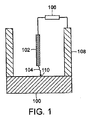
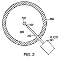
図1及び図2には、OES方法の基本的な要素を示している。導電サンプル100は、電極102の下方に配置される。アークスパーク104は、適当な電子回路106によって発生し、戻り経路108を備え、スパーク104がサンプル100に当たる、非常に局所化された箇所にて、少量の金属を蒸発させる。モノクロに見える及び/又は目に見えない(すなわち、赤外線及び/又は紫外線)光電子放出200(図2)の蒸発した金属の元素の特性は、光ガイド202によって捕捉され、光を分光計204へと送り、スペクトルを分析して、元素の組成をもたらす。
1 and 2 show the basic elements of the OES method. The
測定から導かれた組成を信頼できるものとすべく、代表的にサンプル100の小さな部分について行われる測定は、サンプル100の全体の組成を代表し、例えば、含有物、マトリックス、及び表面汚染物からの影響を最小化するために、標準的な慣行においては、2〜3秒間の測定において、100平方mmの大きさの領域に当てられた、数千のスパークからのスペクトルを平均化している。この多数のスパークが当たることで、代表的に、当たった箇所には、黒くなった領域が残される。
In order to make the composition derived from the measurements reliable, the measurements typically made on a small portion of the
高度な技術では、1回の測定における数千のスパークからの個々のスペクトルを記録及び分析し、異常なスペクトルを排除し、サンプル100のバルクについて、最も信頼できる組成分析を得る。しかしながら、このとき、個別のスパークがサンプル100のどこに当たったのかを決定するためのいかなる方法も存在せず、故に、個々のスパークの位置は、スパークで励起された材料の元素組成と相関させることができない。
Advanced techniques record and analyze individual spectra from thousands of sparks in a single measurement, eliminate anomalous spectra, and obtain the most reliable composition analysis for the bulk of
本発明の実施形態は、サンプルの組成の分析と、単一の励起ビームを用いて分析される、サンプルでの位置の確認との両方のための装置を提供する。装置は、サンプルの少なくとも一部分に励起ビームを当てるためのビーム発生器を具備している。サンプルの少なくとも一部分にビームを当てることで、サンプルの少なくとも一部分は励起して、音を発生させる。サンプルの少なくとも一部分が励起したとき、光信号が発生する。また、装置は、光信号を受けるように配置された分光計を具備している。分光計は、受けた光信号からスペクトルを発生させる。また、装置は、少なくとも2つのマイクロホンを具備している。マイクロホンは、ビーム発生器の付近において、互いに間隔を隔てた位置に配置されている。装置はさらに、少なくとも2つのマイクロホンに結合されてなる、タイミングモジュールを具備している。タイミングモジュールは、少なくとも2つのマイクロホンによって受けた音のタイミングと、少なくとも2つのマイクロホンの位置とに少なくとも部分的に基づき、音の発生源の位置を確認するように働く。 Embodiments of the present invention provide an apparatus for both analyzing the composition of a sample and confirming the location on the sample that is analyzed using a single excitation beam. The apparatus includes a beam generator for applying an excitation beam to at least a portion of the sample. By applying a beam to at least a portion of the sample, at least a portion of the sample is excited to generate sound. An optical signal is generated when at least a portion of the sample is excited. The apparatus also includes a spectrometer arranged to receive the optical signal. The spectrometer generates a spectrum from the received optical signal. The apparatus also includes at least two microphones. The microphones are arranged at positions spaced from each other in the vicinity of the beam generator. The apparatus further includes a timing module coupled to the at least two microphones. The timing module serves to ascertain the position of the sound source based at least in part on the timing of the sound received by the at least two microphones and the position of the at least two microphones.
任意的には、装置は、スタート信号の発生源を具備している。スタート信号は、励起ビームが発生された時間を指示する。タイミングモジュールは、スタート信号の発生源と結合されている。タイミングモジュールは、スタート信号に少なくとも部分的に基づき、音の発生源の位置を確認する。 Optionally, the device comprises a source of start signals. The start signal indicates the time when the excitation beam was generated. The timing module is coupled to the source of the start signal. The timing module determines the position of the sound source based at least in part on the start signal.
ひとつの実施形態においては、スタート信号の発生源は、フォトダイオードを具備している。 In one embodiment, the source of the start signal comprises a photodiode.
他の実施形態においては、スタート信号の発生源は、励起ビームを発生する回路の少なくとも一部分を具備している。 In other embodiments, the source of the start signal comprises at least a portion of a circuit that generates the excitation beam.
任意的には、装置は、タイミングモジュールに接続された回路を具備している。回路は、発生したスペクトルを、確認された音の発生源の位置と相関させる。 Optionally, the apparatus comprises a circuit connected to the timing module. The circuit correlates the generated spectrum with the location of the identified sound source.
さらに別の実施形態においては、少なくとも2つのマイクロホンは、少なくとも3つのマイクロホンを具備している。マイクロホンは、ビーム発生器の付近において、互いに間隔を隔てた位置に配置されている。タイミングモジュールは、少なくとも3つのマイクロホンに接続される。タイミングモジュールは、少なくとも3つのマイクロホンで受けた音のタイミングと、少なくとも3つのマイクロホンの位置とに少なくとも部分的に基づき、音源の位置を確認する。 In yet another embodiment, the at least two microphones comprise at least three microphones. The microphones are arranged at positions spaced from each other in the vicinity of the beam generator. The timing module is connected to at least three microphones. The timing module determines the position of the sound source based at least in part on the timing of the sound received by the at least three microphones and the position of the at least three microphones.
ひとつの実施形態においては、少なくとも2つのマイクロホンのそれぞれは、圧力波検出器の直線状のアレイを具備している。 In one embodiment, each of the at least two microphones comprises a linear array of pressure wave detectors.
他の実施形態においては、少なくとも2つのマイクロホンのそれぞれは、ガス媒体によって、サンプルから隔てられている。 In other embodiments, each of the at least two microphones is separated from the sample by a gas medium.
変形例としては、少なくとも2つのマイクロホンのそれぞれは、サンプルと機械的に接触している。 As a variant, each of the at least two microphones is in mechanical contact with the sample.
ひとつの実施形態においては、少なくとも2つのマイクロホンのそれぞれは、サンプルに対して垂直に向けられている。 In one embodiment, each of the at least two microphones is oriented perpendicular to the sample.
変形例としては、少なくとも2つのマイクロホンのそれぞれは、サンプルに対して垂直以外に向けられている。 As a variant, each of the at least two microphones is oriented other than perpendicular to the sample.
ひとつの実施形態においては、ビーム発生器は、電極を具備し、励起ビームは、スパークである。 In one embodiment, the beam generator comprises electrodes and the excitation beam is a spark.
他の実施形態においては、ビーム発生器は、レーザを具備している。 In other embodiments, the beam generator comprises a laser.
本発明の別の実施形態は、サンプルでの位置を確認する方法を提供する。方法は、サンプルを提供する段階を具備している。サンプルの少なくとも一部分は、組成について分析される。また、方法は、サンプルに当てられる励起ビームを発生させる段階を具備している。サンプルにビームを当てると、音が発生し、サンプルの少なくとも一部分が励起される。また、方法は、音の発生源の位置を決定する段階を具備している。位置の決定は、音が少なくとも2つの既知の位置に達するのに要する移動時間に、少なくとも部分的に基づく。また、位置の決定は、少なくとも2つの既知の位置の配置に、少なくとも部分的に基づく。 Another embodiment of the present invention provides a method for confirming a location on a sample. The method includes providing a sample. At least a portion of the sample is analyzed for composition. The method also includes generating an excitation beam that is applied to the sample. When the beam is applied to the sample, sound is generated and at least a portion of the sample is excited. The method also includes determining the location of the sound source. The position determination is based at least in part on the travel time it takes for the sound to reach at least two known positions. Also, the position determination is based at least in part on the arrangement of at least two known positions.
任意的には、方法は、サンプルの少なくとも一部分における励起によって発生した、光信号からスペクトルを発生させる段階を具備している。この場合には、方法は、発生したスペクトルを、決定された音の発生源の位置に相関させる段階を具備している。 Optionally, the method comprises generating a spectrum from the optical signal generated by excitation in at least a portion of the sample. In this case, the method comprises correlating the generated spectrum with the position of the determined sound source.
ひとつの実施形態においては、励起ビームを発生する段階は、サンプルに当たるスパークを発生させる段階を具備している。スパークを発生させる段階は、音を発生させ、サンプルの少なくとも一部分を蒸発させる。 In one embodiment, generating the excitation beam comprises generating a spark that strikes the sample. The step of generating sparks generates sound and evaporates at least a portion of the sample.
他の実施形態においては、励起ビームを発生させる段階は、レーザビームを発生させて、サンプルの少なくとも一部分を照射する段階を具備している。レーザビームを発生して、サンプルの少なくとも一部分を照射する段階は、音を発生させ、サンプルの少なくとも一部分からプラズマを発生させる。 In other embodiments, generating the excitation beam comprises generating a laser beam to irradiate at least a portion of the sample. Generating the laser beam to irradiate at least a portion of the sample generates sound and generates a plasma from at least a portion of the sample.
任意的には、方法は、サンプルにおける第2の既知の位置に当たる励起ビームを発生させる段階を具備し、それにより、第2の音を発生させる。この場合には、方法は、第2の音が少なくともひとつの既知の位置に達するのに要する移動時間を測定する段階を具備している。音の発生源の位置の決定は、第2の音が少なくともひとつの既知の位置に達するのに要する移動時間に、少なくとも部分的に基づく。 Optionally, the method comprises generating an excitation beam that strikes a second known position in the sample, thereby generating a second sound. In this case, the method comprises measuring the travel time required for the second sound to reach at least one known position. The determination of the position of the sound source is based at least in part on the travel time required for the second sound to reach at least one known position.
本発明のさらに別の実施形態においては、ビーム発生器からの励起ビームをサンプルに当てることで発生した光信号から、分光計によって発生したスペクトルを相関させる装置が提供される。装置は、励起ビームが発生した時間を指示する、スタート信号の源を具備している。また、装置は、スタート信号に対して、所定の時間に、分光計によって発生したスペクトルを記録する回路を具備している。 In yet another embodiment of the invention, an apparatus is provided for correlating a spectrum generated by a spectrometer from an optical signal generated by applying an excitation beam from a beam generator to a sample. The apparatus includes a source of start signals that indicate the time at which the excitation beam was generated. The apparatus also includes a circuit that records a spectrum generated by the spectrometer at a predetermined time with respect to the start signal.
ひとつの実施形態においては、スタート信号の源は、フォトダイオードを具備している。 In one embodiment, the start signal source comprises a photodiode.
他の実施形態においては、スタート信号の源は、励起ビームを発生させる回路の少なくとも一部分を具備している。 In other embodiments, the source of the start signal comprises at least a portion of a circuit that generates the excitation beam.
任意的には、回路は、所定量の時間にわたって、スペクトルを記録する。 Optionally, the circuit records the spectrum over a predetermined amount of time.
本発明のさらに別の実施形態においては、ビーム発生器からの励起ビームをサンプルに当てることで発生した光信号から、分光計によって発生したスペクトルを相関させる方法が提供される。方法は、励起ビームの発生を検出する段階を具備している。また、方法は、励起ビームの発生の検出に応答して、励起ビームの発生の検出に対して、所定の時間に、分光計によって発生したスペクトルを確認する段階を具備している。 In yet another embodiment of the present invention, a method is provided for correlating a spectrum generated by a spectrometer from an optical signal generated by applying an excitation beam from a beam generator to a sample. The method includes detecting the generation of an excitation beam. The method also includes the step of confirming a spectrum generated by the spectrometer at a predetermined time for detection of excitation beam generation in response to detection of excitation beam generation.
ひとつの実施形態においては、励起ビームの発生を検出する段階は、スパークを検出する段階を具備している。 In one embodiment, detecting the generation of the excitation beam comprises detecting a spark.
他の実施形態においては、励起ビームの発生を検出する段階は、レーザビームを検出する段階を具備している。 In other embodiments, detecting the generation of the excitation beam comprises detecting a laser beam.
本発明の前述した特徴は、添付図面を参照しつつ、以下の詳細な説明を読むことで、より容易に理解される。 The foregoing features of the present invention will be more readily understood upon reading the following detailed description, with reference to the accompanying drawings, in which:
本発明による実施形態は、OESアーク/スパーク装置において、個々のスパークがサンプルのどこに当たったのかを決定するための方法及びシステムを含む。本発明による別の実施形態は、個々のスパークの位置を、スパークによって励起された材料の元素組成に相関させる方法及びシステムを含む。本願に開示される方法及びシステムは、例えば、ミクロン単位の高い空間分解能にて、元素組成の空間分布を決定できる。本開示に従った装置は、空間的に相関した元素分析を行うために、本発明による機器に加えることができる。 Embodiments in accordance with the present invention include methods and systems for determining where an individual spark hits a sample in an OES arc / spark device. Another embodiment according to the present invention includes a method and system that correlates the position of individual sparks with the elemental composition of the material excited by the sparks. The methods and systems disclosed herein can determine the spatial distribution of elemental compositions with high spatial resolution, for example, on the order of microns. An apparatus according to the present disclosure can be added to the instrument according to the present invention for performing spatially correlated elemental analysis.
本発明の別の実施形態においては、興味があるスペクトルが発生し、または、興味がある複数のスペクトルが発生した、時間を決定するための方法及びシステムが含まれる。 In another embodiment of the present invention, a method and system for determining the time at which a spectrum of interest has occurred or multiple spectra of interest have occurred are included.
本発明のさらに別の実施形態においては、個々のスパークの位置を、スパークによって励起した材料の元素組成と相関させる方法及びシステムが含まれる。 In yet another embodiment of the invention, methods and systems are included that correlate the location of individual sparks with the elemental composition of the material excited by the sparks.
本発明の実施形態によって可能となるように、サンプル内の元素組成の空間的な変化を測定することによって、従前には入手できなかった有用な情報を、単一の測定で生じさせることができる。例えば、そうした測定によって、別の方法では均質なサンプルにおける、含有物のサイズ及び位置に関する情報を提供できる。また、測定によって、異なる合金間の境界にわたる、元素の変化に関する情報を提供できる。そうした測定値及び情報は、金属の生産又は取扱いにおいて、汚染物の分析を大いに容易にし、サンプルの元素組成の空間的な同質性を承認することができる。 By enabling the spatial variation of the elemental composition in the sample, as enabled by embodiments of the present invention, useful information not previously available can be generated in a single measurement. . For example, such measurements can provide information regarding the size and location of inclusions in otherwise homogeneous samples. Measurements can also provide information about changes in elements across the boundaries between different alloys. Such measurements and information can greatly facilitate the analysis of contaminants in the production or handling of metals and can approve the spatial homogeneity of the elemental composition of the sample.
[定義]
「励起ビーム」は、単位粒子あたり充分なエネルギーをもった、質量のある又は質量のない粒子の流れであって、サンプルの表面から原子を分離させるものを意味している。例としては、限定はしないが、スパーク中の電子又はイオン、レーザビーム中の光子などが含まれる。
[Definition]
“Excitation beam” means a mass or massless particle stream with sufficient energy per unit particle that separates atoms from the surface of a sample. Examples include, but are not limited to, electrons or ions in a spark, photons in a laser beam, and the like.
「励起」は、サンプルに励起ビームを当てた結果、サンプルの少なくとも一部分に変化を生じ、サンプルの一部分が蒸発するか、サンプルの一部分からプラズマが発生することを意味している。サンプルを励起させると、サンプルの変化によって、サンプルの組成を分析することができる。 “Excitation” means that as a result of applying an excitation beam to a sample, a change occurs in at least a portion of the sample and a portion of the sample evaporates or a plasma is generated from a portion of the sample. When the sample is excited, the composition of the sample can be analyzed by changing the sample.
「ビーム発生器」は、電極、レーザ、又はその他の励起ビームの源であって、サンプルの一部分を充分に励起して、分析すべき励起部分から原子又は分子の放出を可能にするものを意味している。 “Beam generator” means an electrode, laser, or other source of excitation beam that sufficiently excites a portion of a sample to allow emission of atoms or molecules from the excitation portion to be analyzed is doing.
[スパークの空間分布]
電極とサンプルとの間の個々のスパークは、圧力波を空気中(又はその他の媒体中)で発生させ、これを通ってスパークは進行し、金属サンプルに入る。ガス媒体においては、圧力パルスの速度は、ガス媒体中における音速に等しく、標準温度及び圧力の純粋な空気中においては、音速は、およそ33.180×103cm/秒である。金属中における速度は、金属の組成と温度とに応じて変化する。例えば、鋼中における速度は、20℃にて、およそ4.4×105cm/秒である。その他の金属中における速度は、当業者において周知であるか、決定できる。
[Spatial spatial distribution]
Individual sparks between the electrode and the sample generate pressure waves in the air (or other medium) through which the spark travels and enters the metal sample. In the gas medium, the speed of the pressure pulse is equal to the speed of sound in the gas medium, and in pure air at standard temperature and pressure, the speed of sound is approximately 33.180 × 10 3 cm / sec. The speed in the metal varies depending on the metal composition and temperature. For example, the velocity in steel is approximately 4.4 × 10 5 cm / sec at 20 ° C. The rates in other metals are well known or can be determined by those skilled in the art.
本発明の実施形態においては、2以上の高周波数マイクロホンを、ガス媒体中に適当に配置し、または、金属サンプルに適当に配置し、または、サンプルとガスとの両方に配置する。スパークからマイクロホンへの音の到達時間、または、到達時間の違いは、情報をもたらし、情報から、マイクロホンに対するスパークの位置を、もって、スパークの絶対位置を、例えば三角測量によって導く。ガス中及び金属中における正確な音の速度は、マイクロホンに対して一定した既知の正確な位置に、基準となる「コールド」スパークを発生させることで、測定中に決定できる。従って、装置は、基準となるスパークを使用して較正される。 In embodiments of the invention, two or more high frequency microphones are suitably placed in the gas medium, suitably placed on the metal sample, or both the sample and the gas. The arrival time of the sound from the spark to the microphone or the difference in the arrival time provides information, and from the information, the position of the spark relative to the microphone is derived, and the absolute position of the spark is derived, for example, by triangulation. The exact sound velocity in the gas and in the metal can be determined during the measurement by generating a reference “cold” spark at a known, precise position that is constant relative to the microphone. Thus, the device is calibrated using the reference spark.
[ガス媒体中における移動時間の測定]
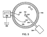
本発明のひとつの実施形態は、図3の上面図と、図4の破断側面図とに示している。簡単のために、図3及び図4には、2つだけのマイクロホン300及び302を示しているが、その他の数のマイクロホンを使用しても良い。一般に、より多くのマイクロホンは、より少ないマイクロホンに比べて、高い精度を提供する。2つのマイクロホン300及び302は、好ましくはメガヘルツ以上の帯域幅をもち、サンプル100と平行な平面404(図4)に配置され、平面は、電極102とサンプル100との間のスパークギャップと交差する。マイクロホン300及び302は、サンプル100とは機械的に接触せず、すなわち、マイクロホン300及び302は、サンプル100から、ガス媒体、例えば標準温度及び圧力の空気によって隔てられている。
[Measurement of travel time in gas medium]
One embodiment of the present invention is shown in the top view of FIG. 3 and the cutaway side view of FIG. For simplicity, FIGS. 3 and 4 show only two
いくつかの実施形態においては、マイクロホン300及び302は、円304上にて、約90゜隔てられ(図3)、円の半径は、例えば、電極102の中心線から約3cmであり、電極102に中心がある。別の実施形態においては、マイクロホン300及び302は、別の角度に配置され、及び/又は、別の半径を有する円に沿って配置される。例えば、3つのマイクロホン(図示せず)を、約120゜隔てて、円上に配置しても良い。
In some embodiments, the
マイクロホンの信号は、スパーク104からマイクロホン300及び302への音波の移動時間を測定するタイミングモジュール306へ送られる。スパーク104のスタートを示すパルス(スタートパルス308)は、スパーク104を開始させる電子回路106から得られ、フォトダイオード又は放電の近くのどこかに配置されたその他の適当な装置310によってピックアップされたスパーク104からの光信号から得られ、または、その他の適当な源から得られる。基準となるスパーク又はノイズ発生器によって測定される、空気中の音波の速度は、33,180cm/秒とされる。
The microphone signal is sent to a
電極102の中心線の正確に下方で、サンプル100に当たるスパークからの音のタイミングを考える。音は、空気を通って、マイクロホン300及び302へ伝わる。それぞれのマイクロホン300及び302からの音の信号は、スタートパルス308の後、約90.42μ秒で、タイミングモジュール306に入る。
3cm/33,180cm/秒=90.42μ秒
Consider the timing of the sound from the spark hitting the
3 cm / 33, 180 cm / sec = 90.42 μsec
0.1μ秒程度のタイミングの不確実性があるので、マイクロホン300及び302からの信号によって決定される、スパークのX及びY位置は、以下の精度にて計算される。
(10-7/90.42)×10-6×3=3.32×10-3cm
Since there is a timing uncertainty of about 0.1 microseconds, the X and Y positions of the spark, determined by the signals from the
(10 −7 /90.42)×10 −6 × 3 = 3.32 × 10 −3 cm
パルス化超音波に使用される商業的なタイミング回路(例えば、非破壊検査に使用されるもの)は、約1ナノセカンド未満の不確実性を有している。従って、適切なタイミング回路を用いれば、スパークの位置(例えばXY座標)は、少なくとも4ミクロン以下で決定することができる。決定されたスパーク104の位置は、分光計204によって発生したスペクトルと相関させられる。従って、組成分析は、分析されたサンプル100の位置と相関させることができる。
Commercial timing circuits used for pulsed ultrasound (eg, those used for nondestructive testing) have uncertainties of less than about 1 nanosecond. Thus, with an appropriate timing circuit, the spark position (eg, XY coordinates) can be determined at least 4 microns or less. The determined location of the
しかしながら、スパーク104は、サンプル100に対して垂直な直線に沿って伝わるか疑わしい。圧力波は、スパーク104の全体に沿って発生する。従って、この圧力波は、時間の範囲にわたって、それぞれのマイクロホン300及び302に達し、スパークの位置の測定に不確実性をもたらす。スパーク104の角度、故に、スパークがサンプル100に当たった位置は、周知の信号処理技術を用いて、2以上のマイクロホンからの波形を分析することで決定される。例えば、3つのマイクロホン(図示せず)を、約120゜隔てて、円上に配置する。
However, it is doubtful that the
変形例としては、それぞれのマイクロホンに置き換えて、サンプル100の表面に対して垂直に向けられた、圧力波検出器の直線状のアレイを用い、アレイの長さをスパークギャップの幅、すなわち、電極102とサンプル100との間の距離に、概略等しくする。
As a variant, a linear array of pressure wave detectors, oriented perpendicular to the surface of the
この実施形態においては、標準温度及び圧力の空気が使用されているけれども、別の実施形態においては、別のガス媒体、温度、及び/又は、圧力を使用しても良い。もちろん、上述した計算は、選択された温度及び圧力における選択されたガス中での音速を考慮にいれて、変更される。 Although standard temperature and pressure air is used in this embodiment, other gas media, temperatures, and / or pressures may be used in other embodiments. Of course, the calculations described above are modified to take into account the speed of sound in the selected gas at the selected temperature and pressure.
上述した実施形態においては、マイクロホン300及び302は、電極102を中心とする円上に配置されているけれども、別の実施形態においては、マイクロホン300及び302は、円上には配置されない。すなわち、電極102の中心線と、マイクロホン300及び302との間の距離は等しくない。そうした実施形態においては、スパークの位置の計算は、マイクロホン300及び302への音の経路の長さの違いを考慮に入れて変更される。
In the above-described embodiment, the
[サンプルの移動時間の測定]
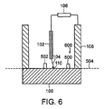
本発明の別の実施形態は、図5の上面図と、図6の破断側面図とに示している。簡単のため、図5及び図6には、2つだけのマイクロホン500及び502又はその他のタイプの圧力センサ又はトランスデューサ(以下、まとめてマイクロホンと称する)を示しているけれども、別の数のマイクロホンを使用しても良い。この実施形態においては、マイクロホン500及び502は、サンプル100に機械的に取り付けられ、サンプル100の内部での音の移動時間が測定される。サンプル100内の音の移動時間の測定は、ガス媒体中の音の移動時間の測定に比べて、より正確なXY位置を提供できる。サンプル100の内部での音の移動時間を測定する実施形態が、現在では好ましい。
[Measurement of sample moving time]
Another embodiment of the present invention is shown in the top view of FIG. 5 and the cutaway side view of FIG. For simplicity, FIGS. 5 and 6 show only two
マイクロホン500及び502は、平面504にてサンプル100に押圧されており、平面504でスパーク104がサンプル100に当たる。マイクロホン500及び502は、サンプル100と機械的に接触し、直接的に、または、中間的な物質を介して、例えば、摩耗板、楔(後述)、音伝導グリースなどを介して接触する。マイクロホンは、好ましくは、電極102の中心線上に中心がある円の上において、約90゜に隔てられている。しかしながら、上述したように、別の角度、半径、及びマイクロホンと電極との間の等しくない距離を使用しても良い。
The
サンプル100内の音波は、スパーク104がサンプル100に当たる箇所にて生起し、音波は、その箇所からマイクロホン500及び502へと伝わる。上述したように、スタートパルス308は、スパーク104のスタートを指示する。タイミングモジュール306は、スパーク104が当たった位置からマイクロホン500及び502までの音波の移動時間、または、移動時間の違いを測定する。スパーク104がサンプル100に当たった箇所のXY位置は、マイクロホン500及び502までの音の移動時間に基づいて、または、移動時間の違いに基づいて計算される。サンプル100中の音波の速度は、基準スパーク又はノイズ発生器を用いて測定され、この測定された速度は、位置決定に使用される。
The sound wave in the
マイクロホン500及び502は、サンプル100の内部を伝わった音に加えて、サンプル100の上方のガス媒体を通って伝わった(スパーク104からの)音を検出する。従って、マイクロホン500及び502は、余分な音を検出する。サンプル100の中を移動する音速は、代表的に、サンプル100の上方のガス媒体中を移動する音速に比べて、1オーダーの大きさだけ高い。従って、ガス媒体を通して伝わる音は、サンプル100を通して伝わる音に比べて、著しく遅く、マイクロホン500及び502に到達する。
任意的には、回路(図示せず)は、ガス媒体を通って伝わった音と、サンプル100を通って伝わった音とを区別して、回路は、ガス媒体を通って伝わった音を無視する。例えば、回路は、所定の時間長さを越えて伝わった(すなわち、スタートパルス308の信号の後、所定の時間長さを越えてマイクロホン500又は502に達した)音を無視し、ここで、所定の時間長さは、スパーク104がサンプル100に当たった箇所110から、サンプル100の最も離れた縁部にまで、音波が伝わるのに必要な時間の長さとおおよそ等しい。変形例としては、回路は、それぞれのマイクロホン500及び502によって検出された第1の音に反応し、回路が次のスタートパルス308の信号を受けるまでは、それぞれのマイクロホンによって続いて検出された音を無視する。
Optionally, a circuit (not shown) distinguishes between sound transmitted through the gas medium and sound transmitted through the
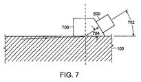
マイクロホン500及び502は、サンプル100の表面に対して垂直に向けられる。変形例としては、図7に示すように、楔700を使用して、それぞれのマイクロホン500及び502を、サンプル100の表面に対して斜めの角度702に向けても良い(図7は、図6の部分600を拡大して示した断面図である。)。マイクロホン500及び502を、サンプル100と楔700との境界を伝わる音の屈折角度704に対応又は近似した、斜めの角度702に向けることで、音の多くの部分をマイクロホン500に導くことができる。
[マイクロホン及びトランスデューサ]
金属の非破壊試験(NDT)のための超音波技術は、膨大な文献をもった成熟した技術である。例えば、NDTに関する基本的な原理、方法、及び用途は、www.ndt-ed.orgから入手可能である。
[Microphone and transducer]
Ultrasound technology for non-destructive testing (NDT) of metals is a mature technology with vast literature. For example, basic principles, methods, and applications for NDT are available from www.ndt-ed.org.
NDTの技術においては、時間分解能が約10-10秒である、トランスデューサが使用される。そうしたトランスデューサを用いれば、サブミクロンの精度にて、スパークの位置を決定し、故に、かかる箇所において蒸発した材料の原子組成を決定することが可能になる。そうしたトランスデューサを用いれば、スタートパルス308と、マイクロホン500又は502に達するスパーク104の音との間の時間は、約ナノセカンド内にて、又はそれをかなり下回って、測定することが可能になる。例えば、スパーク104からマイクロホン500又は502までの平均距離が約2cmであるならば、移動時間は約4ミリセカンドであり、測定された距離における不確実性は、1ナノセカンドの時間分解能について、約5ミクロンになる。
2cm×(10-9秒)/(4×10-6秒)=5×10-4cm
In NDT technology, transducers are used that have a temporal resolution of about 10 −10 seconds. With such a transducer, it is possible to determine the location of the spark with submicron accuracy and hence the atomic composition of the material evaporated at such locations. With such a transducer, the time between the
2 cm × (10 −9 seconds) / (4 × 10 −6 seconds) = 5 × 10 −4 cm
[スパーク時間とスペクトルの相関]
スパーク104がサンプル100に当たる結果、様々なスペクトルが発生する。スペクトルは、可視及び不可視の、例えば赤外線及び/又は紫外線の光を含む。サンプル100の一部分がスパーク104によって蒸発するとき、興味があるスペクトルが発生する。しかしながら、サンプル100の一部分が蒸発する前及び/又は後には、スパーク104がサンプル100に当たった箇所110の上方にある、加熱された又はイオン化されたガスも、スペクトルを発生するが、これにはほとんど又は全く興味がなく、サンプル100の組成の不正確な分析につながる。
[Correlation between spark time and spectrum]
As a result of the
本発明のいくつかの実施形態においては、スパーク104の時間を、分光計204によって検出された様々なスペクトルと相関させて、蒸発したサンプル100から得られたスペクトルを、加熱されたガスから得られたスペクトルから区別する。スパーク104の時間とスペクトルとを相関させることで、スパーク104を発生させる前に、一般的に行われていたように、サンプル100の上方にある加熱されたガスによって発生する不都合なスペクトルを防止し又は減少させるために、例えば、アルゴンを用いて、スパークギャップを洗い流す必要性を低下させ又は解消させる。
In some embodiments of the invention, the time of the
そうしたひとつの実施形態においては、スタートパルス308、または、スパーク104の結果又はスパークに協調する別の時間信号は、分光計204にトリガーをかけて、信号の時間に、分光計204によって検出されたスペクトルを記録する。任意的には、分光計への時間信号を、適当な時間長さだけ遅らせて、信号の時間に分光計で検出されたスペクトルが、興味のあるスペクトルになるようにする。例えば、興味があるスペクトルは、スパーク104がサンプル100に当たった後、所定の時間長さにて検出されたスペクトルである。この遅れは、スパーク104の角度に依存し、故に、スパークがサンプル100に当たる位置に依存するが、これは、マイクロホンからの波形の分析によって決定される。
In one such embodiment, the
いったんトリガーされると、分光計204は、単一のスペクトルを記録し、または、分光計204は、所定の時間長さにわたって、スペクトルを記録する。
Once triggered, the
そうした別の実施形態においては、分光計204は、スペクトルを(例えば、不図示の汎用又は専用コンピュータに)、それぞれのスペクトルが発生した時間を指示するタイムスタンプと共に、記録する。また、スパーク104の時間、及び任意的には、スパーク104がサンプル100に当たった時間も記録される。そして、記録されたスペクトル、及びスパークの(又は当たった)時間を相関させて、興味があるスペクトルを選択する。
In another such embodiment, the
[レーザで誘発された光学発光]
スパークに代えて、別の励起現象を使用して、サンプルを励起させ、分析されるスペクトルを発生させても良い。例えば、1又は複数のレーザを使用して、サンプル又はサンプルの一部分を励起させても良い。レーザによって照射されたサンプルの一部分は、蒸発し、または、サンプルの一部分からプラズマが発生する。本願に開示された方法及びシステムは、レーザ又は他のエネルギービームがサンプルに当たった位置を決定するために使用できる。
[Laser-induced optical emission]
Instead of sparking, another excitation phenomenon may be used to excite the sample and generate a spectrum to be analyzed. For example, one or more lasers may be used to excite a sample or a portion of a sample. A portion of the sample irradiated by the laser evaporates or plasma is generated from the portion of the sample. The methods and systems disclosed herein can be used to determine the position where a laser or other energy beam hits the sample.
本願において、「励起ビーム」という用語は、スパーク、レーザビーム、及びその他の励起現象であって、サンプルの励起に使用できるものを称する。本願において、「励起」という用語は、サンプルに励起ビームを当てた効果であって、サンプルの一部分の蒸発、または、サンプルの一部分からのプラズマの発生を含み、励起したサンプルの一部分の組成の分析を容易にすることを称する。「ビーム発生器」という用語は、電極、レーザ、又はその他の励起ビームの源を称する。 In this application, the term “excitation beam” refers to sparks, laser beams, and other excitation phenomena that can be used to excite a sample. As used herein, the term “excitation” is the effect of applying an excitation beam to a sample, including evaporation of a portion of the sample or generation of a plasma from a portion of the sample, and analysis of the composition of the portion of the excited sample. It refers to facilitating. The term “beam generator” refers to an electrode, laser, or other source of excitation beam.
[結論]
上述したように、時には多くの(時には数千の)スペクトルが、単一のサンプルから集められる。それぞれのスパークは、絶縁材料の層を残す傾向があるので、その後のスパークは、サンプル上の既に当たった位置には、当たりそうにない。従って、スパークは、サンプルの領域にわたって分配される傾向がある。
[Conclusion]
As mentioned above, sometimes many (sometimes thousands) of spectra are collected from a single sample. Since each spark tends to leave a layer of insulating material, subsequent sparks are unlikely to hit the already hit location on the sample. Thus, the spark tends to be distributed over the area of the sample.
本願に開示された方法及び装置を用いることで、それぞれのスパークが当たった位置は、それに対応するスペクトルと相関させられる。故に、それぞれのスパークで励起された材料の元素組成は、スパークが当たった位置と相関させることができる。その結果、サンプル内の元素組成の空間的な分布を決定することができる。元素組成の空間的な分布は、別の具合では均質であるサンプルにおける、含有物のサイズ及び位置に関する情報を提供できる。また、このデータは、異なる合金の間の境界を横切る、元素変化に関する情報を提供できる。そうした測定値及び情報は、金属の生産又は取扱いにおいて、汚染物の分析を大いに容易にし、サンプルの元素組成の空間的な同質性を承認することができる。 Using the method and apparatus disclosed herein, the location of each spark hit is correlated with the corresponding spectrum. Thus, the elemental composition of the material excited by each spark can be correlated with the location where the spark hits. As a result, the spatial distribution of the elemental composition within the sample can be determined. The spatial distribution of elemental composition can provide information about the size and location of inclusions in samples that are otherwise homogeneous. This data can also provide information on elemental changes across the boundaries between different alloys. Such measurements and information can greatly facilitate the analysis of contaminants in the production or handling of metals and can approve the spatial homogeneity of the elemental composition of the sample.
励起ビームが当たった位置と、当たった場所におけるサンプルの元素組成との両方を、単一のビームを当てることで決定することができる。これは、経済的で正確なシステムを提供する。 Both the location where the excitation beam struck and the elemental composition of the sample at the location where it struck can be determined by applying a single beam. This provides an economical and accurate system.
本発明について、上述した例示的な実施形態に関して説明したけれども、当業者が理解するように、本願で開示された発明の概念から逸脱せずに、例示した実施形態に改変及び変更を施すことができる。さらに、好ましい実施形態は、様々なマイクロホン、トランスデューサ、及び圧力センサに関連させて説明したけれども、当業者が理解するように、システム及び方法は、音又は圧力波を検出可能な様々なセンサを用いて実施することができる。従って、本発明は、特許請求の範囲の精神及び範囲を除き、制限されるものではない。 Although the present invention has been described with reference to the above-described exemplary embodiments, those skilled in the art will appreciate that modifications and changes can be made to the illustrated embodiments without departing from the inventive concepts disclosed herein. it can. Further, although the preferred embodiment has been described in connection with various microphones, transducers, and pressure sensors, as those skilled in the art will appreciate, the system and method employ various sensors that can detect sound or pressure waves. Can be implemented. Accordingly, the invention is not limited except as by the spirit and scope of the appended claims.
100 サンプル
102 電極
104 アークスパーク
106 電子回路
108 戻り経路
200 光電子放出
202 光ガイド
204 分光計
300,302 マイクロホン
304 円
306 タイミングモジュール
308 スタートパルス
404 平面
500,502 マイクロホン
504 平面
700 楔
702 斜めの角度
704 屈折角度
100
Claims (25)
サンプルの少なくとも一部分に励起ビームを当てるためのビーム発生器であって、それにより、サンプルの少なくとも一部分を励起し、音を発生させる上記ビーム発生器と、
サンプルの少なくとも一部分が励起されたときに発生した光信号を受けるように配置され、受けた光信号からスペクトルを発生させる分光計と、
ビーム発生器の付近において、互いに間隔を隔てた位置に配置されてなる少なくとも2つのマイクロホンと、
少なくとも2つのマイクロホンに接続されたタイミングモジュールであって、少なくとも2つのマイクロホンによって受けた音のタイミングと,少なくとも2つのマイクロホンの位置と,に少なくとも部分的に基づき、音の源の位置を確認するように働く、上記タイミングモジュールと、
を備えていることを特徴とする装置。 A device that performs both analysis of the composition of a sample analyzed using a single excitation beam and confirmation of its position in the sample,
A beam generator for applying an excitation beam to at least a portion of the sample, thereby exciting at least a portion of the sample and generating sound;
A spectrometer arranged to receive an optical signal generated when at least a portion of the sample is excited, and generating a spectrum from the received optical signal;
In the vicinity of the beam generator, at least two microphones arranged at a distance from each other;
A timing module connected to at least two microphones, wherein the position of the sound source is ascertained based at least in part on the timing of the sound received by the at least two microphones and the position of the at least two microphones; With the above timing module,
A device characterized by comprising:
タイミングモジュールは、少なくとも3つのマイクロホンに接続され、少なくとも3つのマイクロホンによって受けた音のタイミングと,少なくとも3つのマイクロホンの位置と,に少なくとも部分的に基づき、音の源の位置を確認するように働く、ことを特徴とする請求項1に記載の装置。 The at least two microphones comprise at least three microphones spaced from each other in the vicinity of the beam generator;
The timing module is connected to at least three microphones and serves to ascertain the position of the sound source based at least in part on the timing of the sound received by the at least three microphones and the position of the at least three microphones. The apparatus according to claim 1.
少なくとも一部分の組成を分析すべき、サンプルを提供する段階と、
サンプルに当てる励起ビームを発生させて、それにより、音を発生させ、サンプルの少なくとも一部分を励起する段階と、
少なくとも2つの既知の位置に音が達するのに要する移動時間と,少なくとも2つの既知の位置についての配置と,に少なくとも部分的に基づき、音の源の位置を決定する段階と、を備えていることを特徴とする方法。 A method for confirming a position in a sample,
Providing a sample to be analyzed for at least a portion of the composition;
Generating an excitation beam that impinges on the sample, thereby generating sound and exciting at least a portion of the sample;
Determining a position of a sound source based at least in part on a travel time required for the sound to reach at least two known positions and an arrangement with respect to the at least two known positions. A method characterized by that.
発生したスペクトルを決定された音の源の位置に相関させる段階と、
をさらに備えていることを特徴とする請求項14に記載の方法。 Generating a spectrum from an optical signal generated by excitation of at least a portion of the sample;
Correlating the generated spectrum with the determined sound source location;
15. The method of claim 14, further comprising:
第2の音が少なくともひとつの既知の位置に達するのに要する移動時間を測定する段階と、をさらに備え、
第2の音が少なくともひとつの既知の位置に達するのに要する、測定された移動時間に少なくとも部分的に基づき、音の源の位置を決定する、
ことを特徴とする請求項14に記載の方法。 Generating an excitation beam applied to the sample at a second known location, thereby generating a second sound;
Measuring the travel time required for the second sound to reach at least one known position;
Determining the position of the source of the sound based at least in part on the measured travel time required for the second sound to reach at least one known position;
15. The method of claim 14, wherein:
励起ビームが発生した時間を指示するスタート信号の源と、
スタート信号に対して、所定の時間に、分光計によって発生したスペクトルを記録する回路と、を備えていることを特徴とする装置。 An apparatus for correlating a spectrum generated by a spectrometer from an optical signal generated by applying an excitation beam from a beam generator to a sample,
A source of a start signal indicating the time at which the excitation beam was generated;
And a circuit for recording a spectrum generated by the spectrometer at a predetermined time with respect to the start signal.
励起ビームの発生を検出する段階と、
励起ビームの発生の検出に応答して、励起ビームの発生の検出に対して、所定の時間に、分光計によって発生したスペクトルを特定する段階と、
を備えていることを特徴とする方法。 A method of correlating a spectrum generated by a spectrometer from an optical signal generated by applying an excitation beam from a beam generator to a sample,
Detecting the generation of an excitation beam;
In response to detecting the generation of the excitation beam, identifying a spectrum generated by the spectrometer at a predetermined time for detection of the generation of the excitation beam;
A method characterized by comprising:
Applications Claiming Priority (2)
| Application Number | Priority Date | Filing Date | Title |
|---|---|---|---|
| US70066405P | 2005-07-20 | 2005-07-20 | |
| PCT/US2006/027374 WO2007011729A2 (en) | 2005-07-20 | 2006-07-13 | Arc/spark optical emission spectroscopy correlated with spark location |
Publications (2)
| Publication Number | Publication Date |
|---|---|
| JP2009503448A true JP2009503448A (en) | 2009-01-29 |
| JP2009503448A5 JP2009503448A5 (en) | 2009-07-16 |
Family
ID=37256875
Family Applications (1)
| Application Number | Title | Priority Date | Filing Date |
|---|---|---|---|
| JP2008522841A Ceased JP2009503448A (en) | 2005-07-20 | 2006-07-13 | Arc / spark emission analysis correlated with spark location |
Country Status (5)
| Country | Link |
|---|---|
| US (1) | US7391508B2 (en) |
| EP (1) | EP1907827A2 (en) |
| JP (1) | JP2009503448A (en) |
| CA (1) | CA2614819A1 (en) |
| WO (1) | WO2007011729A2 (en) |
Cited By (1)
| Publication number | Priority date | Publication date | Assignee | Title |
|---|---|---|---|---|
| KR101242936B1 (en) | 2010-08-03 | 2013-03-12 | 주식회사 포스코 | Optical Emission Spectroscope Having Function Of Measuring Location Of Spark And Method For Measuring Location Of Spark In Optical Emission Spectroscope |
Families Citing this family (7)
| Publication number | Priority date | Publication date | Assignee | Title |
|---|---|---|---|---|
| US9072169B1 (en) | 2010-07-13 | 2015-06-30 | Cascodium Inc. | Pulse generator and systems and methods for using same |
| US8963555B2 (en) * | 2011-05-13 | 2015-02-24 | General Electric Company | Methods, systems, and apparatus for detecting light and acoustic waves |
| DE102015210123B4 (en) * | 2015-06-02 | 2022-03-17 | Deutsches Zentrum für Luft- und Raumfahrt e.V. | Measuring system for gas analysis and method for gas analysis |
| EP3260778B1 (en) * | 2016-06-21 | 2021-07-21 | John Zink Company, L.L.C. | System and method for electrical spark detection |
| JP6823555B2 (en) * | 2017-07-05 | 2021-02-03 | アークレイ株式会社 | Plasma spectroscopic analysis method |
| JP6754326B2 (en) * | 2017-07-05 | 2020-09-09 | アークレイ株式会社 | Plasma spectroscopic analysis method |
| HUP1900246A1 (en) * | 2019-07-05 | 2021-01-28 | Univ Szegedi | Method and equipment for monitoring a spark particle generator |
Citations (5)
| Publication number | Priority date | Publication date | Assignee | Title |
|---|---|---|---|---|
| JPH0310148A (en) * | 1989-06-08 | 1991-01-17 | Shimadzu Corp | Light emission analyzing apparatus |
| JPH03146891A (en) * | 1989-09-26 | 1991-06-21 | Cyber Scient Inc | Acoustic position detector |
| JP2001066255A (en) * | 1999-08-26 | 2001-03-16 | Fujikura Ltd | Sample for measuring field light emission |
| JP2002122544A (en) * | 2000-10-16 | 2002-04-26 | Shimadzu Corp | Emission analyzing device |
| JP2002159926A (en) * | 2000-11-27 | 2002-06-04 | Japan Steel Works Ltd:The | Device and method for detecting cleaned state of substrate surface during laser cleaning |
Family Cites Families (17)
| Publication number | Priority date | Publication date | Assignee | Title |
|---|---|---|---|---|
| US4641250A (en) * | 1984-06-11 | 1987-02-03 | The United States Of America As Represented By The Secretary Of The Air Force | Inspection workstation data entry method |
| US4804603A (en) * | 1987-09-21 | 1989-02-14 | Eastman Kodak Company | Electrophotographic method and apparatus |
| US4973800A (en) * | 1988-12-15 | 1990-11-27 | Science Accessories Corp. | Apparatus for digitizing positions on a transparency |
| DE69014398T2 (en) | 1989-04-29 | 1995-04-20 | Fisons Plc | Method and device for optical emission spectroscopy. |
| US4956824A (en) * | 1989-09-12 | 1990-09-11 | Science Accessories Corp. | Position determination apparatus |
| US5050134A (en) * | 1990-01-19 | 1991-09-17 | Science Accessories Corp. | Position determining apparatus |
| US5009277A (en) * | 1990-03-19 | 1991-04-23 | Science Accessories Corp. | Method and apparatus for position determination |
| US5252834A (en) * | 1990-11-13 | 1993-10-12 | Union Oil Company Of California | Pulsed and gated multi-mode microspectrophotometry device and method |
| US5216817A (en) * | 1992-03-18 | 1993-06-08 | Colgate-Palmolive Company | Digitizer measuring system |
| US5308936A (en) * | 1992-08-26 | 1994-05-03 | Mark S. Knighton | Ultrasonic pen-type data input device |
| US5379269A (en) * | 1993-01-13 | 1995-01-03 | Science Accessories Corp. | Position determining apparatus |
| US6008896A (en) * | 1998-07-01 | 1999-12-28 | National Research Council Of Canada | Method and apparatus for spectroscopic analysis of heterogeneous materials |
| US6466309B1 (en) * | 1999-02-26 | 2002-10-15 | California Institute Of Technology | Method and apparatus for chemical and topographical microanalysis |
| US6359687B1 (en) * | 1999-10-12 | 2002-03-19 | Lockheed Martin Energy Research Corporation | Aerosol beam-focus laser-induced plasma spectrometer device |
| US6777953B2 (en) * | 2001-01-24 | 2004-08-17 | General Dynamics (Otc) Aerospace, Inc. | Parallel arc fault diagnostic for aircraft wiring |
| WO2003085376A2 (en) | 2002-04-03 | 2003-10-16 | The Regents Of The University Of California | System and method for quantitative or qualitative measurement of exogenous substances in tissue and other materials using laser-induced fluorescence spectroscopy |
| US6784429B2 (en) * | 2002-04-19 | 2004-08-31 | Energy Research Company | Apparatus and method for in situ, real time measurements of properties of liquids |
-
2006
- 2006-07-13 WO PCT/US2006/027374 patent/WO2007011729A2/en active Application Filing
- 2006-07-13 EP EP06787302A patent/EP1907827A2/en not_active Withdrawn
- 2006-07-13 US US11/486,439 patent/US7391508B2/en not_active Expired - Fee Related
- 2006-07-13 CA CA002614819A patent/CA2614819A1/en not_active Abandoned
- 2006-07-13 JP JP2008522841A patent/JP2009503448A/en not_active Ceased
Patent Citations (5)
| Publication number | Priority date | Publication date | Assignee | Title |
|---|---|---|---|---|
| JPH0310148A (en) * | 1989-06-08 | 1991-01-17 | Shimadzu Corp | Light emission analyzing apparatus |
| JPH03146891A (en) * | 1989-09-26 | 1991-06-21 | Cyber Scient Inc | Acoustic position detector |
| JP2001066255A (en) * | 1999-08-26 | 2001-03-16 | Fujikura Ltd | Sample for measuring field light emission |
| JP2002122544A (en) * | 2000-10-16 | 2002-04-26 | Shimadzu Corp | Emission analyzing device |
| JP2002159926A (en) * | 2000-11-27 | 2002-06-04 | Japan Steel Works Ltd:The | Device and method for detecting cleaned state of substrate surface during laser cleaning |
Cited By (1)
| Publication number | Priority date | Publication date | Assignee | Title |
|---|---|---|---|---|
| KR101242936B1 (en) | 2010-08-03 | 2013-03-12 | 주식회사 포스코 | Optical Emission Spectroscope Having Function Of Measuring Location Of Spark And Method For Measuring Location Of Spark In Optical Emission Spectroscope |
Also Published As
| Publication number | Publication date |
|---|---|
| US20070019182A1 (en) | 2007-01-25 |
| US7391508B2 (en) | 2008-06-24 |
| WO2007011729A2 (en) | 2007-01-25 |
| WO2007011729A3 (en) | 2007-04-26 |
| EP1907827A2 (en) | 2008-04-09 |
| CA2614819A1 (en) | 2007-01-25 |
Similar Documents
| Publication | Publication Date | Title |
|---|---|---|
| JP2009503448A (en) | Arc / spark emission analysis correlated with spark location | |
| US11229954B2 (en) | Additive manufacturing apparatus and method | |
| US6008896A (en) | Method and apparatus for spectroscopic analysis of heterogeneous materials | |
| Rusak et al. | Recent trends and the future of laser-induced plasma spectroscopy | |
| EP0963540B1 (en) | System and method for laser ultrasonic bond integrity evaluation | |
| áL LACOUR | Correction of matrix effects in quantitative elemental analysis with laser ablation optical emission spectrometry | |
| KR100625000B1 (en) | Method and apparatus for quantitative sputter target cleanliness characterization | |
| US20030140710A1 (en) | Method of and apparatus for measuring and evaluating material strength by detecting charged particles | |
| Cai et al. | Photoacoustic monitoring of the mass removed in pulsed laser ablation | |
| Fortes et al. | Characteristics of solid aerosols produced by optical catapulting studied by laser-induced breakdown spectroscopy | |
| US9121830B2 (en) | Spectrometer apparatus using continuous wave laser and photomultiplier tube | |
| JP2009503448A5 (en) | ||
| Hosseini et al. | Multi-parameter characterization of the longitudinal plasma profile of a filament: a comparative study | |
| CN112378930A (en) | Pulse laser-based cladding layer surface and deep layer flaw detection method | |
| US6134001A (en) | Fluid diagnostic technique | |
| US6601451B1 (en) | System and method to provide material property measurement using re-entrant ultrasound | |
| CA2287024C (en) | Method and apparatus for spectroscopic analysis of heterogeneous materials | |
| US20010037671A1 (en) | Laser apparatus for measuring dirt density on steel plates | |
| WO1996031900A1 (en) | A method and device for the analysis of the chemical composition of particles | |
| JPH0562639A (en) | Atomic arrangement stereo-analysis method and apparatus therefor | |
| WO2002103347A2 (en) | Grain-size measurement | |
| JPH07280752A (en) | Highly sensitive surface multi-element simultaneous mass spectrometry | |
| JPH07294459A (en) | Sputter neutral particle mass spectrometry | |
| Farquar et al. | Supramicrometer particle shadowgraph imaging in the ionization region of a single particle aerosol mass spectrometer | |
| US8671759B2 (en) | Method and apparatus for measuring amount of material removed from target in pulsed laser ablation |
Legal Events
| Date | Code | Title | Description |
|---|---|---|---|
| A521 | Request for written amendment filed |
Free format text: JAPANESE INTERMEDIATE CODE: A523 Effective date: 20090529 |
|
| A621 | Written request for application examination |
Free format text: JAPANESE INTERMEDIATE CODE: A621 Effective date: 20090529 |
|
| A131 | Notification of reasons for refusal |
Free format text: JAPANESE INTERMEDIATE CODE: A131 Effective date: 20111205 |
|
| A01 | Written decision to grant a patent or to grant a registration (utility model) |
Free format text: JAPANESE INTERMEDIATE CODE: A01 Effective date: 20120521 |
|
| A045 | Written measure of dismissal of application [lapsed due to lack of payment] |
Free format text: JAPANESE INTERMEDIATE CODE: A045 Effective date: 20120924 |