JP2009278432A - Imaging apparatus, and imaging method in imaging apparatus - Google Patents
Imaging apparatus, and imaging method in imaging apparatus Download PDFInfo
- Publication number
- JP2009278432A JP2009278432A JP2008128400A JP2008128400A JP2009278432A JP 2009278432 A JP2009278432 A JP 2009278432A JP 2008128400 A JP2008128400 A JP 2008128400A JP 2008128400 A JP2008128400 A JP 2008128400A JP 2009278432 A JP2009278432 A JP 2009278432A
- Authority
- JP
- Japan
- Prior art keywords
- image
- frame
- unit
- movement amount
- detection
- Prior art date
- Legal status (The legal status is an assumption and is not a legal conclusion. Google has not performed a legal analysis and makes no representation as to the accuracy of the status listed.)
- Pending
Links
Images


Landscapes
- Studio Devices (AREA)
Abstract
Description
本発明は、撮像装置およびこの撮像装置における撮像方法に関するものである。 The present invention relates to an imaging apparatus and an imaging method in the imaging apparatus.
従来から、デジタルカメラ等の撮像装置において、複数の撮影画像を合成してパノラマ画像を生成するパノラマ撮影モードを備えたものが知られており、撮像装置をパンニングさせながら被写体を部分毎に撮影し、撮影した画像データを合成することによって、この部分毎の撮影画像が繋ぎ合されたパノラマ画像を得ることができる。デジタルカメラでは、撮像素子からの出力を所定のフレームレートで表示部に表示させることにより電子ファインダーとして用いているが、パノラマ撮影モードでは、このライブビュー画像間の動きをフレーム毎に検出して積算することによって画像の移動量を求め、撮影画像間の繋ぎ目を検出するようにしている。これによれば、継ぎ目に違和感が生じない適切なタイミングで撮影処理を行うことができる。例えば、特許文献1には、パンニングに伴う画像間の動き(動きベクトル)を求め、この動きベクトルをもとに撮影画像を繋ぎ合わせる際の幅を制御する技術が開示されている。
Conventionally, an imaging device such as a digital camera is known which has a panoramic shooting mode for generating a panoramic image by synthesizing a plurality of captured images, and the subject is photographed for each part while panning the imaging device. By synthesizing the photographed image data, a panoramic image in which the photographed images for each part are connected can be obtained. In digital cameras, the output from the image sensor is displayed on the display unit at a predetermined frame rate and used as an electronic viewfinder. In the panorama shooting mode, the motion between live view images is detected and integrated for each frame. Thus, the amount of movement of the image is obtained, and the joint between the captured images is detected. According to this, it is possible to perform the photographing process at an appropriate timing that does not cause a sense of incongruity at the joint. For example,
ところで、フレーム毎にライブビュー画像間の動きを検出してライブビュー画像の移動量を求める場合、例えばフレームレートが30(フレーム/秒)とすると、1枚目の撮影から2枚目の撮影までのパンニング操作の所要時間が3秒であれば90回の動き検出を行うこととなる。ここで、動き検出では、実際の移動量に対する検出誤差が生じ得る。このため、動き検出の結果を積算して画像の移動量を算出する場合、動き検出の度に生じた誤差が積算されていくこととなり、ライブビュー画像の移動量を精度良く算出できないという問題があった。またこの結果、合成時の繋ぎ目にズレが生じ、生成したパノラマ画像に違和感が生じる場合があった。 By the way, when the movement between the live view images is detected for each frame to obtain the moving amount of the live view image, for example, when the frame rate is 30 (frames / second), from the first shooting to the second shooting. If the time required for the panning operation is 3 seconds, motion detection is performed 90 times. Here, in motion detection, a detection error with respect to the actual movement amount may occur. For this reason, when the movement amount of the image is calculated by integrating the motion detection results, the error generated each time the motion is detected is integrated, and the movement amount of the live view image cannot be calculated accurately. there were. As a result, there is a case where a gap occurs in the joint at the time of synthesis, and the generated panoramic image is uncomfortable.
本発明は、上記に鑑みてなされたものであって、画像間の動き検出誤差を低減し、画像の移動量を精度良く決定することができる撮像装置およびこの撮像装置における撮像方法を提供することを目的とする。 The present invention has been made in view of the above, and provides an imaging apparatus capable of reducing motion detection errors between images and accurately determining the amount of image movement, and an imaging method in the imaging apparatus. With the goal.
上述した課題を解決し、目的を達成するため、本発明にかかる撮像装置は、被写体を撮像して画像データを生成する撮像部を備え、複数回の撮影処理を行って複数の撮影画像を生成する撮像装置であって、前記撮像部によって撮像された前記画像データを所定のフレーム単位で切り換えて表示する表示部と、前記現フレームの画像と前記現フレームと隣接する隣接フレームの画像との間の動きを検出する隣接フレーム間動き検出部と、前記現フレームの画像と所定の基準フレームの画像との間の動きを検出する基準フレーム間動き検出部と、前記隣接フレーム間動き検出部の検出結果および前記基準フレーム間動き検出部の検出結果をもとに、各検出結果についての信頼度を評価する信頼度評価部と、前記信頼度評価部の評価結果をもとに、前記隣接フレーム間動き検出部の検出結果および/または前記基準フレーム間動き検出部の検出結果を用いて前記基準フレームから現フレームまでの画像移動量を決定する移動量決定部と、前記移動量決定部によって決定される画像移動量をもとに前記撮影処理の開始を指示する撮影開始指示部と、を備えることを特徴とする。 In order to solve the above-described problems and achieve the object, an imaging apparatus according to the present invention includes an imaging unit that images a subject and generates image data, and performs a plurality of imaging processes to generate a plurality of captured images. An image pickup apparatus, wherein the image data picked up by the image pickup unit is displayed by switching in a predetermined frame unit, and an image of the current frame and an image of an adjacent frame adjacent to the current frame. Detection of motion between adjacent frames, detection of motion between reference frames, and detection of motion between adjacent frames, and detection of motion between adjacent frames Based on the result and the detection result of the reference inter-frame motion detection unit, based on the reliability evaluation unit that evaluates the reliability of each detection result, and the evaluation result of the reliability evaluation unit, A movement amount determination unit that determines an image movement amount from the reference frame to the current frame using a detection result of the inter-frame motion detection unit and / or a detection result of the reference inter-frame motion detection unit, and the movement amount determination A photographing start instruction unit that instructs the start of the photographing process based on an image movement amount determined by the unit.
また、本発明にかかる撮像装置は、上記の発明において、現フレームの画像上に、前記移動量決定部によって決定される画像移動量に従って移動する移動マークと、該移動マークの移動目標位置を示す移動目標マークとを表示する制御を行う表示制御部を備え、前記撮影開始指示部は、前記移動目標マークが示す前記移動目標位置に前記移動マークが移動した場合に、前記撮影処理の開始を指示することを特徴とする。 In the image pickup apparatus according to the present invention, in the above invention, a moving mark that moves according to an image moving amount determined by the moving amount determining unit and a movement target position of the moving mark are displayed on the image of the current frame. A display control unit that performs control to display a movement target mark, and the imaging start instruction unit instructs to start the imaging process when the movement mark moves to the movement target position indicated by the movement target mark It is characterized by doing.
また、本発明にかかる撮像装置は、上記の発明において、前記信頼度評価部は、前記各検出結果についての信頼度の評価結果をもとに、前記各検出結果の信頼性の有無を判定することを特徴とする。 In the imaging device according to the present invention, in the above invention, the reliability evaluation unit determines whether or not each detection result is reliable based on a reliability evaluation result for each detection result. It is characterized by that.
また、本発明にかかる撮像装置は、上記の発明において、前記移動量決定部は、前記信頼度評価部による評価の結果、前記各検出結果の双方が信頼性有りと判定された場合に、少なくとも前記基準フレーム間動き検出部の検出結果を用いて前記画像移動量を決定することを特徴とする。 Further, in the imaging apparatus according to the present invention, in the above invention, the movement amount determination unit is at least when both the detection results are determined to be reliable as a result of the evaluation by the reliability evaluation unit. The image movement amount is determined using a detection result of the reference inter-frame motion detection unit.
また、本発明にかかる撮像装置は、上記の発明において、前記移動量決定部は、前記信頼度評価部による評価の結果、前記各検出結果の双方が信頼性有りと判定された場合に、前記隣接フレーム間動き検出部の検出結果によって定まる前記基準フレームから現フレームまでの画像移動量と、前記基準フレーム間動き検出部の検出結果によって定まる前記基準フレームから現フレームまでの画像移動量との平均値を前記画像移動量として決定することを特徴とする。 Further, in the imaging device according to the present invention, in the above invention, when the movement amount determination unit determines that both of the detection results are reliable as a result of the evaluation by the reliability evaluation unit, The average of the image movement amount from the reference frame to the current frame determined by the detection result of the motion detection unit between adjacent frames and the image movement amount from the reference frame to the current frame determined by the detection result of the motion detection unit between the reference frames A value is determined as the image movement amount.
また、本発明にかかる撮像装置は、上記の発明において、前記移動量決定部は、前記信頼度評価部による評価の結果、前記各検出結果の双方が信頼性有りと判定された場合に、前記隣接フレーム間動き検出部の検出結果および前記基準フレーム間動き検出部の検出結果に対して対応する信頼度の重み付けを行って前記画像移動量を決定することを特徴とする。 Further, in the imaging device according to the present invention, in the above invention, when the movement amount determination unit determines that both of the detection results are reliable as a result of the evaluation by the reliability evaluation unit, The image movement amount is determined by performing corresponding weighting on the detection result of the inter-adjacent frame motion detection unit and the detection result of the reference inter-frame motion detection unit.
また、本発明にかかる撮像装置は、上記の発明において、前記移動量決定部は、前記信頼度評価部による評価の結果、前記各検出結果のうちの一方の検出結果が信頼性無しと判定された場合に、信頼性有りと判定された他方の検出結果を用いて前記画像移動量を決定することを特徴とする。 In the imaging device according to the present invention, in the above invention, the movement amount determination unit determines that one of the detection results is unreliable as a result of the evaluation by the reliability evaluation unit. In this case, the image movement amount is determined using the other detection result determined to be reliable.
また、本発明にかかる撮像装置は、上記の発明において、前記移動量決定部は、前記信頼度評価部による評価の結果、前記基準フレーム間動き検出部の検出結果が信頼性有りと判定された場合には前記基準フレーム間動き検出部の検出結果を用いて前記画像移動量を決定し、前記基準フレーム間動き検出部の検出結果が信頼性無しと判定された場合には前記隣接フレーム間動き検出部の検出結果を用いて前記画像移動量を決定することを特徴とする。 In the imaging device according to the present invention, in the above invention, the movement amount determination unit determines that the detection result of the inter-frame motion detection unit is reliable as a result of the evaluation by the reliability evaluation unit. In this case, the image movement amount is determined using the detection result of the reference inter-frame motion detection unit, and when the detection result of the reference inter-frame motion detection unit is determined to be unreliable, the inter-adjacent frame motion is determined. The image movement amount is determined using a detection result of a detection unit.
また、本発明にかかる撮像装置は、上記の発明において、前記移動量決定部は、前記信頼度評価部による評価の結果、前記各検出結果の双方が信頼性無しと判定された場合に、現フレームの画像および前記現フレームと隣接する隣接フレームの画像との間の動きを推定して前記画像移動量を決定することを特徴とする。 Further, in the imaging apparatus according to the present invention, in the above invention, the movement amount determination unit is configured to display a current state when both of the detection results are determined to be unreliable as a result of the evaluation by the reliability evaluation unit. The image movement amount is determined by estimating a motion between an image of a frame and an image of an adjacent frame adjacent to the current frame.
また、本発明にかかる撮像装置は、上記の発明において、前記信頼度評価部による評価の結果、前記基準フレーム間動き検出部の検出結果が信頼性無しと判定された場合に、前記基準フレームを現フレームに変更する基準フレーム変更部を備えることを特徴とする。 In the imaging device according to the present invention, in the above invention, when the detection result of the inter-frame motion detection unit is determined to be unreliable as a result of the evaluation by the reliability evaluation unit, A reference frame changing unit for changing to the current frame is provided.
また、本発明にかかる撮像装置における撮像方法は、被写体を撮像して画像データを生成する撮像部を備え、複数回の撮影処理を行って複数の撮影画像を生成する撮像装置における撮像方法であって、前記撮像部によって撮像された前記画像データを所定のフレーム単位で切り換えて表示する表示ステップと、前記現フレームの画像と前記現フレームと隣接する隣接フレームの画像との間の動きを検出する隣接フレーム間動き検出ステップと、前記現フレームの画像と所定の基準フレームの画像との間の動きを検出する基準フレーム間動き検出ステップと、前記隣接フレーム間動き検出ステップでの検出結果および前記基準フレーム間動き検出ステップでの検出結果をもとに、各検出結果についての信頼度を評価する信頼度評価ステップと、前記信頼度評価ステップでの評価結果をもとに、前記隣接フレーム間動き検出ステップでの検出結果および/または前記基準フレーム間動き検出ステップでの検出結果を用いて前記基準フレームから現フレームまでの画像移動量を決定する移動量決定ステップと、前記移動量決定ステップで決定される画像移動量をもとに前記撮影処理の開始を指示する撮影開始指示ステップと、を含むことを特徴とする。 An imaging method in an imaging apparatus according to the present invention is an imaging method in an imaging apparatus that includes an imaging unit that images a subject and generates image data, and generates a plurality of captured images by performing a plurality of imaging processes. And detecting a motion between the display step of switching and displaying the image data picked up by the image pickup unit in units of a predetermined frame and the image of the current frame and the image of an adjacent frame adjacent to the current frame. A motion detection step between adjacent frames, a motion detection step between reference frames for detecting a motion between an image of the current frame and an image of a predetermined reference frame, a detection result in the motion detection step between adjacent frames, and the reference Based on the detection result in the inter-frame motion detection step, a reliability evaluation step for evaluating the reliability of each detection result; Based on the evaluation result in the reliability evaluation step, the detection result in the inter-adjacent frame motion detection step and / or the detection result in the reference inter-frame motion detection step is used to determine from the reference frame to the current frame. A movement amount determination step for determining an image movement amount; and a photographing start instruction step for instructing the start of the photographing process based on the image movement amount determined in the movement amount determination step.
本発明によれば、現フレームの画像と隣接フレームの画像との間の隣接フレーム間の動きを検出するとともに、現フレームの画像と所定の基準フレームの画像との間の基準フレーム間の動きを検出し、各検出結果についての信頼度の評価結果をもとに、隣接フレーム間の検出結果および/または基準フレーム間の検出結果を用いて基準フレームから現フレームまでの画像移動量を決定することができる。例えば、基準フレーム間の検出結果についての信頼度の評価が高ければ、画像移動量を決定する際に基準フレーム間の検出結果を用いることができるので、画像間の動き検出誤差を低減することができ、画像の移動量を精度良く決定できるという効果を奏する。 According to the present invention, the motion between adjacent frames between the current frame image and the adjacent frame image is detected, and the motion between the reference frames between the current frame image and the predetermined reference frame image is detected. Detecting and determining the amount of image movement from the reference frame to the current frame using the detection result between adjacent frames and / or the detection result between the reference frames based on the reliability evaluation result for each detection result Can do. For example, if the reliability evaluation of the detection result between the reference frames is high, the detection result between the reference frames can be used when determining the image movement amount, so that the motion detection error between images can be reduced. This is advantageous in that the amount of movement of the image can be determined with high accuracy.
以下、図面を参照し、本発明の好適な実施の形態について詳細に説明する。本実施の形態では、本発明の撮像装置をデジタルカメラに適用した場合を例にとって説明する。 DESCRIPTION OF EMBODIMENTS Hereinafter, preferred embodiments of the present invention will be described in detail with reference to the drawings. In this embodiment, a case where the imaging device of the present invention is applied to a digital camera will be described as an example.
(実施の形態)
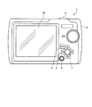
図1は、デジタルカメラ1の背面図である。図1に示すように、デジタルカメラ1は、カメラ本体2の上面に配設された撮影タイミングを指示するためのシャッターボタン(レリーズボタン)3、カメラ本体2の背面に配設された電源ボタン4やメニューボタン5、上下左右の各方向ボタン(上ボタン、下ボタン、左ボタンおよび右ボタン)を有する十字ボタン6、操作内容を確定する等のためのOKボタン7、各種画面を表示する表示部22等を備えている。また、図示しないが、カメラ本体2の前面には、ファインダーや撮像レンズ等が配設されている。ユーザが電源ボタン4を押下し、電源をONすると、デジタルカメラ1は撮影可能な状態(撮影モード)となる。この撮影モードでは、撮像レンズを通して撮像素子12(図2参照)に結像されている被写体像が1フレーム(例えば1/30秒)毎に取り込まれ、ライブビュー画像として表示部22にリアルタイムに表示されるようになっている。そして、例えばシャッターボタン3の押下タイミング等で電子的な撮影が行われる。
(Embodiment)
FIG. 1 is a rear view of the
先ず、このデジタルカメラ1の構成について説明する。図2は、デジタルカメラ1の構成例を示す概略ブロック図である。図2に示すように、デジタルカメラ1は、撮像光学系11、撮像部としての撮像素子12、AFE(Analog Front End)13、フレームメモリ14、動き検出部15、画像処理部16、記録媒体I/F17、記録媒体保持部18、記録媒体19、ビデオエンコーダ20、表示ドライバ21、表示部22、ビデオ信号出力端子23、操作部24、RAM25、ROM26、コントローラ27等を備える。
First, the configuration of the
撮像光学系11は、撮像レンズ、絞り、シャッター等を含み、入射される被写体像を撮像素子12に結像する。撮像素子12は、例えばCCD(Charge Coupled Device)やCMOS(Complementary Metal Oxide Semiconductor)等の固体撮像素子であり、被写体からの光束を撮像光学系11を介して受光し、光電変換することによってフレーム単位の画像データ(アナログ電気信号)を得るものである。AFE13は、撮像素子12によって得られる画像データに対してCDS(Correlated Double Sampling)やAGC(Automatic Gain Control)等のアナログ信号処理を施した後、A/D変換処理を施してデジタル電気信号に変換する。AFE13によってデジタル化された画像データは、フレームメモリ14および動き検出部15に出力されるとともに、RAM25に一時的に記憶される。
The imaging optical system 11 includes an imaging lens, a diaphragm, a shutter, and the like, and forms an incident subject image on the
フレームメモリ14は、動き検出部15による作業用メモリとして用いられ、2フレーム分の画像データを記憶するための領域を備える。図3は、フレームメモリ14の内部構成を示す模式図であり、フレームメモリ14には、現フレームの画像(現フレーム画像)の画像データである現フレームデータ141と、直前フレームの画像(直前フレーム画像)の画像データである直前フレームデータ143と、所定の基準フレームの画像(基準フレーム画像)の画像データである基準フレームデータ145とが記憶される。
The
動き検出部15は、AFE13からの画像データをもとに、フレーム間の動きを検出するためのものであり、例えば1フレーム毎に撮像素子12から取り込まれてAFE13から出力される画像間の動きベクトルを求めることによって、フレーム間の動きを検出する。図4は、動き検出部15が行う動き検出の概要を説明する説明図である。本実施の形態では、現フレームと隣接する1フレーム前のフレームを現フレームの直前に取り込まれた直前フレームとする。そして、動き検出部15は、AFE13から随時入力されてフレームメモリ14に記憶される現フレームデータ141と直前フレームデータ143との間でパタンマッチングを行い、画像の移動量を表す動きベクトルを直前フレーム間検出結果として算出することによって、隣接フレーム間動き検出部として機能する。また、動き検出部15は、現フレームデータ141を基準フレームデータ145との間でパタンマッチングを行い、画像の移動量を表す動きベクトルを基準フレーム間検出結果として算出することによって、基準フレーム間動き検出部として機能する。
The
図5は、この動き検出部15の機能構成を示す模式図である。図5に示すように、動き検出部15は、前述のようにして検出した直前フレーム間検出結果および基準フレーム間検出結果の信頼度を評価する信頼度評価部151と、信頼度評価部151による評価結果をもとに、直前フレーム間検出結果および/または基準フレーム間検出結果を用いて動き検出を開始した基準フレームから現フレームまでの画像移動量を決定する移動量決定部153と、信頼度評価部151による評価結果をもとに基準フレームの設定を更新し、基準フレーム変更部として機能する動き検出エリア設定部155とを含む。また、図示しないが、動き検出部15は、直前フレーム間検出結果や基準フレーム間検出結果、各検出結果の信頼度の評価結果、動き検出エリアの設定情報等を一時的に記憶しておくためのRAMを内部に備えている。
FIG. 5 is a schematic diagram showing a functional configuration of the
画像処理部16は、図2に示すように、RAM25に一旦記憶された画像データを読み出し、この画像データに対して各種の画像処理を施すとともに、記録用、表示用、パノラマ合成用等に適した画像データに変換する処理を行う。例えば、撮影画像やパノラマ画像の画像データを記録する際、あるいは記録されている画像データを表示する際等に、JPEG(Joint Photographic Experts Group)方式等に基づく画像データの圧縮処理や伸張処理を行う。また、パノラマ撮影モード中に撮影された連続性のある複数の撮影画像の画像データを合成し、1枚のパノラマ画像を生成する処理等を行う。この画像処理部16で画像処理された画像データは、記録媒体I/F17に出力されて記録媒体19に記録され、あるいはビデオエンコーダ20に出力されて表示部22に表示される。
As shown in FIG. 2, the
ビデオエンコーダ20は、表示用に変換された画像データを表示ドライバ21に送出する。例えば撮影モードでは、1フレーム毎に撮像素子12から取り込まれて画像処理部16によって画像処理された画像をフレーム単位で表示部22に切換表示させ、ライブビュー画像の表示を行う。一方、再生モードでは、記録媒体19から読み出されて画像処理部16よって画像処理された撮影画像やパノラマ画像を表示部22に表示させる。また、このビデオエンコーダ20は、ビデオ信号出力端子23に接続された外部機器に対し、必要に応じて表示用の画像データを出力する。表示部22は、撮影画像やライブビュー画像の他、デジタルカメラ1の各種設定情報等を表示するためのものであり、LCD(Liquid Crystal Display)やELディスプレイ(Electroluminescence Display)等の表示装置で実現される。
The video encoder 20 sends the image data converted for display to the
記録媒体I/F17は、記録媒体保持部18によって挿脱自在に保持される記録媒体19に対して、記録用に変換された画像データ等の書き込みや、記録された画像データの読み出し等を行う。記録媒体19は、例えばxD−ピクチャーカード(登録商標)やコンパクトフラッシュ(登録商標)カード等のメモリカードである。
The recording medium I /
操作部24は、撮影タイミングの指示や、パノラマ撮影モードを含む各種の撮影モードや再生モードといったモードの設定操作、撮影条件の設定操作等、ユーザによる各種操作を受け付けて操作信号をコントローラ27に通知するためのものであり、各種機能が割り当てられたボタンスイッチ等で実現される。この操作部24は、図1のシャッターボタン3、電源ボタン4、メニューボタン5、十字ボタン6、およびOKボタン7を含む。
The
ROM26は、デジタルカメラ1を動作させ、このデジタルカメラ1が備える種々の機能を実現するための各種のカメラプログラムや、このカメラプログラムの実行中に使用されるデータ等を予め記憶する。RAM25は、画像処理部16やコントローラ27の作業用メモリとして用いられる。例えば、AFE13からの画像データ等が一時的に記憶され、表示部22に表示するライブビュー画像の画像データを生成する際の作業用やパノラマ画像を生成する際の作業用、撮影画像やパノラマ画像を記録媒体19に記録する際の作業用に用いられる。
The
コントローラ27は、操作部24からの操作信号等に応じてROM26からカメラプログラムを読み出して実行し、デジタルカメラ1を構成する各部の動作制御やメモリ制御を行ってデジタルカメラ1全体の動作を統括的に制御する。また、AF(自動焦点)、AE(自動露出)、AWB(自動ホワイトバランス)等の処理を行う。このコントローラ27は、パノラマ撮影モードにおいて撮影処理の開始タイミングを指示する撮影開始指示部271を含む。
The controller 27 reads out and executes a camera program from the
次に、以上のように構成されるデジタルカメラ1の撮影モードの一つであるパノラマ撮影モードについて説明する。図6は、パノラマ撮影モードの概要を説明する図である。パノラマ撮影モードでは、複数回の撮影処理を行って、複数の画像(以下、パノラマ画像用に撮影される撮影画像を「部分画像」という。)の画像データを生成する。例えば、ユーザは、シャッターボタン3を押下し、1枚目の部分画像を撮影する。その後カメラ本体2を所定のパノラマ撮影方向へとパンニング操作して、2枚目の部分画像撮影位置に達したところで2枚目の部分画像を撮影する。以後、任意の枚数の部分画像の撮影を繰り返すことで、被写体を部分毎に撮影する。パンニング操作とは、パノラマ撮影方向に沿ってカメラ本体2を回転させながら移動させる操作のことをいう。図6では、ユーザが、シャッターボタン3の押下後にカメラ本体2を左側から右側に向けて水平方向にパンニング操作し、例えば3枚の部分画像I1,I3,I5を撮影した場合を示している。ここで、各部分画像I1,I3,I5の撮影処理は、1枚目の部分画像I1についてはシャッターボタン3の押下タイミングで行われる。2枚目以降の部分画像I3,I5については、ユーザによるカメラ本体2のパンニング操作の途中で自動的に行われる。そして、このようにして生成した部分毎の部分画像I1,I3,I5を、それぞれ隣り合う部分画像I1,I3,I5間の位置関係が合うように繋ぎ合わせて合成し、1枚のパノラマ画像I7を生成する。具体的には、部分画像I1の右端の領域A1と、部分画像I3の左端の領域A3とに映る重複部分を探索し、探索された重複部分をもとに、部分画像I1と部分画像I3とを合成する。同様にして、部分画像I3の右側の領域A5と、部分画像I5の左側の領域A7とに映る重複部分をもとに、部分画像I3と部分画像I5とを合成する。
Next, a panoramic shooting mode that is one of the shooting modes of the
このように、パノラマ画像を生成するためには、各部分画像の所定範囲が重複している必要があるが、一方で、重複部分が所定範囲からずれると合成箇所の探索処理に時間を要し、合成処理時間が増大してしまう。また、重複部分が著しく所定範囲からずれると、合成箇所を検出することができず、合成の結果、継ぎ目に違和感のあるパノラマ画像となる。このため、2枚目以降の部分画像の撮影処理は、重複部分が適切な範囲となるようなタイミングで行う必要がある。本実施の形態では、1枚目の撮影処理の後、動き検出部15が行う動き検出処理の結果決定される画像移動量に従って移動する移動マークとしてのポインタと、このポインタの移動目標位置を示す移動目標マークとしてのターゲットとを表示する。具体的には、部分画像の所定範囲が重複するように次の撮影位置を定める。そして、この次の撮影位置に従ってポインタおよびポインタの移動目標位置(ターゲットの位置)を設定し、ポインタとターゲットとをライブビュー画像上に配置することによって、ポインタをターゲット上に移動させるようなパンニング操作を促す。
As described above, in order to generate a panoramic image, the predetermined range of each partial image needs to overlap. On the other hand, if the overlapping portion deviates from the predetermined range, it takes time to search for a synthesis location. The synthesis processing time increases. Further, if the overlapping portion is significantly deviated from the predetermined range, the synthesized portion cannot be detected, and as a result of the synthesis, a panoramic image having a sense of incongruity is formed at the joint. For this reason, it is necessary to perform the imaging processing of the second and subsequent partial images at a timing such that the overlapping portion falls within an appropriate range. In the present embodiment, a pointer as a movement mark that moves according to an image movement amount determined as a result of the motion detection process performed by the
図7は、パノラマ撮影を行う際のデジタルカメラ1の操作を説明するための図であり、パノラマ撮影モードにおいて表示部22に表示される表示画面の遷移例を示している。パノラマ撮影モードでは先ず、ライブビュー画像の表示が開始される(図7(a))。そして、シャッターボタン3が押下されるまで待機状態となる。ユーザは、このライブビュー画像を見ながらシャッターボタン3を押下し、1枚目の部分画像の撮影タイミングを指示する。撮影タイミングを指示すると撮影処理が開始され、1枚目の部分画像が生成される。
FIG. 7 is a diagram for explaining the operation of the
1枚目の撮影を終えると、続いてライブビュー画像上にポインタPMとターゲットTMとが表示され(図7(b))、2枚目の部分画像を撮影するためのターゲットTMへのパンニング操作を促す。ここで、図7は、パノラマ撮影方向が“右”の場合の操作例を示しており、図7(b)に向かって右側にポインタPMが、左側にターゲットTMが配置されている。パノラマ撮影方向は、例えばユーザが「右」または「左」のいずれか一方を選択することで確定される。なお、パノラマ撮影方向が“左”の場合には、ポインタは画面左側、ターゲットは画面右側を初期位置として配置される。ユーザがカメラ本体2を右方向に向けて水平方向にパンニング操作すると、ポインタPMは、ライブビュー画像とともにターゲットTMが配置される左側へと移動していく(図7(c))。そして、ポインタPMがターゲットTMの枠内に移動すると(図7(d))、撮影処理が自動的に開始される。
When the first image is taken, the pointer PM and the target TM are displayed on the live view image (FIG. 7B), and the panning operation to the target TM for taking the second partial image is performed. Prompt. Here, FIG. 7 shows an operation example when the panoramic shooting direction is “right”, and the pointer PM is arranged on the right side and the target TM is arranged on the left side in FIG. 7B. The panorama shooting direction is determined, for example, when the user selects either “right” or “left”. When the panorama shooting direction is “left”, the pointer is arranged at the initial position on the left side of the screen and the target is arranged on the right side of the screen. When the user pans the
次に、動き検出処理の原理について説明する。この動き検出処理では、動き検出部15による動き検出と、信頼度評価部151による信頼度の評価と、移動量決定部153による画像移動量の決定と、動き検出エリア設定部155による動き検出エリアの設定とを行う。なお、ここでは、パノラマ撮影方向が“右”の場合を例にとって説明する。
Next, the principle of the motion detection process will be described. In this motion detection process, motion detection by the
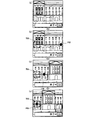
先ず、動き検出部15が行う動き検出について説明する。図4に示して説明したように、動き検出部15は、現フレーム画像と直前フレーム画像との間(直前フレーム間)の動きを検出するとともに、現フレーム画像と基準フレーム画像との間(基準フレーム間)の動きを検出するが、このとき、画角範囲(被写体範囲)に対してそれぞれ個別に設定される動き検出エリアを対象に動き検出を行う。図8は、動き検出エリアの一例を示す図である。また、図9は、直前フレーム間の動き検出について説明するための図であり、直前フレームの画角範囲(直前フレーム画像)の一例を示している。また、図10は、基準フレーム間の動き検出について説明するための図であり、基準フレームの画角範囲(基準フレーム画像)の一例を示している。
First, motion detection performed by the
直前フレーム間の動き検出では、動き検出部15は、図8に示すように、直前フレームの画角範囲Evのほぼ全域に一点鎖線で示す直前フレーム間検出エリアEbを設定して動き検出を行う。動き検出部15は先ず、図9に示すように、直前フレーム画像中の直前フレーム間検出エリアEb内に複数の代表点B11を配置する。配置する代表点の位置や数等は、例えば予め設定しておく。また、現フレーム画像中に、直前フレーム画像中に配置した各代表点に対する探索範囲を設定する。そして、直前フレームの各代表点と、対応する探索範囲とでパタンマッチングを行って最もマッチングする(相関が高い)位置を現フレーム画像中の各探索範囲の中から探索する。そして、パタンマッチングによって得られた各代表点の動きベクトルをもとに、フレーム間検出エリアEbの動きを示す代表動きベクトルを求める。
In the motion detection between the immediately preceding frames, as shown in FIG. 8, the
一方、基準フレーム間の動き検出では、動き検出部15は、図8中に二点鎖線で示すように、直前フレーム間検出エリアEbと比較して狭い基準フレーム間検出エリアEdを基準フレーム画像中に設定して動き検出を行う。この基準フレーム間検出エリアEdは、パノラマ撮影方向が“右”の場合、画角範囲Evの右端位置に設定される。なお、パノラマ撮影方向が“左”の場合、画角範囲Evの左端位置に設定される。動き検出部15は、先ず、図10に示すように、基準フレーム画像中の所定位置(右端位置)に基準フレーム間検出エリアEdを設定する。そして、動き検出部15は、この基準フレーム間検出エリアEd内に複数の代表点B21を配置する。配置する代表点の位置や数等は、例えば予め設定しておく。また、現フレーム画像中に、基準フレーム画像中に配置した各代表点に対する探索範囲を設定する。なお、詳細は後述するが、本実施の形態では、この現フレーム画像中に設定される探索範囲の位置が、現フレーム画像中の所定位置(右端位置)を初期位置として移動するようになっている。そして、直前フレーム間の動き検出と同様にして、基準フレームの各代表点とこれに対する探索範囲とでパタンマッチングを行い、最もマッチングする位置を現フレーム中の各探索範囲の中から探索する。そして、パタンマッチングにより得られた各代表点の動きベクトルをもとに、基準フレーム間検出エリアEdの動きを示す代表動きベクトルを求める。
On the other hand, in motion detection between the reference frames, the
次に、信頼度評価部151が行う信頼度の評価について説明する。信頼度評価部151は、直前フレーム間検出結果および基準フレーム間検出結果の信頼度を算出し、信頼性の有無を判定する。例えば、マッチング失敗数が多い場合や、得られた各代表点に対する各動きベクトルの方向に統一性が無い場合、あるいは動き検出対象の各フレームの画像が縞模様や格子模様等の繰り返し画像である場合や、無地の壁を写したようなコントラストの小さい画像の場合等では、検出結果の信頼性が低いと考えられる。そこで、代表点数に対するマッチング成功数を第1の評価パラメータとして算出する。また、マッチングが成功している動きベクトルをその方向毎にグループ分けして要素数の最大値を選出し、マッチング成功数に対する要素数の最大値を第2の評価パラメータとして算出する。また、動き検出対象の各フレームが繰り返し画像のときには、パタンマッチングの際に相関の高い動きベクトルが複数探索される場合があるが、探索された動きベクトル位置の数が多いほど小さくなるように第3の評価パラメータの値を算出する。さらに、現フレーム画像についてパタンマッチングにより得られる相関演算結果のヒストグラムを作成し、分布幅が狭い程値が小さくなるように第4の評価パラメータを算出する。具体的には、信頼度評価部151は、直前フレーム間検出結果および基準フレーム間検出結果の各検出結果についてそれぞれ各評価パラメータの算出を行い、例えばそれぞれの合計値を対応する検出結果についての信頼度の値とする。そして、信頼度評価部151は、得られた信頼度が予め設定される所定の閾値を超えているか否かによって、各検出結果の信頼性の有無を判定する。
Next, the reliability evaluation performed by the
次に、移動量決定部153が行う画像移動量の算出および動き検出エリア設定部155による動き検出エリアの設定について説明する。移動量決定部153は、動き検出を開始した基準フレームから現フレームまでの画像移動量を決定するが、このとき、基準フレーム間検出結果に信頼性が有る場合には、この基準フレーム間検出結果を用いて画像移動量を決定する。基準フレーム間検出結果に信頼性が無い場合であって、直前フレーム間検出結果に信頼性が有る場合には、この直前フレーム間検出結果を用いて画像移動量を決定する。一方、動き検出エリア設定部155は、1枚目の部分画像の撮影の後、図9に示して説明したように、直前フレーム画像中に直前フレーム間検出エリアを設定して代表点を配置する。また、動き検出エリア設定部155は、現フレームを基準フレームに設定し、基準移動量を“0”に初期化する。そして、動き検出エリア設定部155は、図10に示して説明したように、基準フレーム画像中に基準フレーム間検出エリアを設定して代表点を配置するとともに、各代表点に対する現フレーム画像中の探索範囲を初期位置(右端位置)に設定する。そして、動き検出部15の基準フレーム間検出結果に信頼性が有る場合には、移動量決定部153が決定した画像移動量に従って、現フレーム画像中の探索範囲の設定位置を移動させる。基準フレーム間検出結果に信頼性が無い場合には、基準フレームを現フレームに変更し、基準フレーム間検出の代表点を初期位置(右端位置)に設定する。また、基準フレームの変更に伴い、次回の動き検出の際に現フレーム画像中に設定する探索範囲を初期位置(右端位置)に再設定する。そしてこのとき、基準移動量を現在の画像移動量の値に更新する。
Next, calculation of the image movement amount performed by the movement
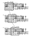
図11および図12は、本実施の形態の動き検出の原理について説明するための説明図であり、風景を被写体としたカメラ本体2のパンニング操作に伴う画角範囲Evの変位を示している。また、図11および図12中において、画角範囲Evとともに、直前フレーム間動き検出対象領域Es1と基準フレーム間動き検出対象領域Es2とを示している。ここで、直前フレーム間動き検出対象領域Es1とは、直前フレーム間の動き検出のための探索範囲が設定される現フレーム画像中の領域を示しており、直前フレーム間の動き検出では、現フレーム画像中の略全域を対象として動き検出を行う。なお、実際の処理では、図9を参照して説明したように、直前フレーム画像中の直前フレーム間検出エリアに配置した各代表点に対する探索範囲が、図11に示す直前フレーム間動き検出対象領域Es1内にそれぞれ設定されることとなる。一方、基準フレーム間動き検出対象領域Es2とは、基準フレーム間の動き検出のための探索範囲が設定される現フレーム画像中の領域を示しており、基準フレーム間の動き検出では、現フレーム画像中の一部の領域を対象として動き検出を行う。なお、実際の処理では、図10を参照して説明したように、基準フレーム画像中の基準フレーム間検出エリアに配置した各代表点に対する探索範囲が、図11に示す基準フレーム間動き検出対象領域Es2内の各位置に設定されることとなる。そして、基準フレーム間検出結果が信頼性有りと判定された場合には、この基準フレーム間検出結果に応じて、探索範囲が設定される基準フレーム間動き検出対象領域Es2が変位する。
FIG. 11 and FIG. 12 are explanatory diagrams for explaining the principle of motion detection according to the present embodiment, and show the displacement of the field angle range Ev accompanying the panning operation of the
より具体的には、図11は、基準フレーム間検出結果が継続して信頼性有りと判定された場合の基準フレーム間動き検出対象領域Es2の変位を示している。そして、図11(a)に示す画角範囲Evは、1枚目の部分画像の撮影の後における現フレームの画角範囲を示しており、画角範囲が図11(a)に示す画角範囲Evのときの基準フレーム間動き検出対象領域Es2は、画角範囲Evの右端に位置している。その後のパノラマ撮影方向である右方向へのパンニング操作に伴い、信頼度評価部151によって基準フレーム間検出結果が信頼性有りと判定されている間は、基準フレーム間動き検出対象領域Es2は、図11(b),(c)に示すように、画像移動量に応じて左端側へと変位していく。例えば、現フレームの画角範囲が図11(b)に示す画角範囲Evに変位したときに動き検出部15が行った基準フレーム間検出結果について、信頼度評価部151が信頼性有りと判定したとする。この場合、移動量決定部153は、得られた基準フレーム間検出結果から画像移動量を決定する。一方、動き検出エリア設定部155は、移動量決定部153が決定した画像移動量をもとに、次回の基準フレーム間の動き検出の際に現フレーム画像中の探索範囲の設定位置を移動させる。
More specifically, FIG. 11 illustrates the displacement of the reference inter-frame motion detection target area Es2 when the detection result between the reference frames is continuously determined to be reliable. An angle of view range Ev shown in FIG. 11A indicates the angle of view range of the current frame after the first partial image is captured, and the angle of view range is the angle of view shown in FIG. The reference inter-frame motion detection target area Es2 in the range Ev is located at the right end of the field angle range Ev. With the subsequent panning operation to the right, which is the panoramic shooting direction, while the
一方、図12は、基準フレーム間検出結果が途中で信頼性無しと判定された場合の基準フレーム間動き検出対象領域Es2の変位を示している。例えば、現フレームの画角範囲が図12(b)に示す画角範囲Evに変位したときに動き検出部15が行った基準フレーム間検出結果について、信頼度評価部151が信頼性無しと判定したとする。この場合には、基準フレーム間動き検出対象領域Es2は、図12(c)に示すように、初期位置である画角範囲Evの右端に位置している。具体的には、移動量決定部153は、直前フレームとの間で行った直前フレーム間検出結果と、画像移動量の前回値とから画像移動量を決定する。一方、動き検出エリア設定部155は、次回の基準フレーム間の動き検出の際に現フレーム画像中の探索範囲を初期位置である右端位置に再設定する。またこのとき、動き検出エリア設定部155は、基準移動量を移動量決定部153が決定した画像移動量とする。
On the other hand, FIG. 12 shows the displacement of the reference inter-frame motion detection target region Es2 when it is determined that the reference inter-frame detection result is not reliable. For example, the
次に、デジタルカメラ1の動作について説明する。図13は、デジタルカメラ1の状態遷移図である。図13に示すように、デジタルカメラ1は、電源ボタン4が押下されて電源がONされると(a1)、カメラ電源OFF状態C1から静止画撮影待機状態C3に遷移し、撮影モードとなる。撮影モードでは、撮像素子12に結像されている被写体像の画像データをRAM25に記憶し、この画像データをフレーム単位で切り換えて表示部22に表示する一連の処理を繰り返し行い、ライブビュー画像の表示を継続的に行う。また、電源ボタン4が押下されて電源がOFFされると(a3)、デジタルカメラ1は、カメラ電源OFF状態C1へと遷移する。
Next, the operation of the
そして、パノラマ撮影モードが選択されると(a5)、デジタルカメラ1は、静止画撮影待機状態C3から撮影状態C5へと遷移する。ここで、1枚目の部分画像の撮影に際しては、シャッターボタン3の押下タイミングで撮影処理を開始する。そして、撮影を完了すると(a7)、デジタルカメラ1は、撮影状態C5から撮影方向検出状態C7へと遷移する。ここでは、ライブビュー画像の動きを検出することによってカメラ本体2のパンニング操作を検出し、パノラマ撮影方向を確定する。パノラマ撮影方向が確定すると(a9)、デジタルカメラ1は、撮影方向検出状態C7から移動量検出状態C9へと遷移する。ここでは先ず、ライブビュー画像上にポインタとターゲットとを表示させる。そして、直前フレーム間での動き検出と基準フレーム間での動き検出とを行い、基準フレームから現フレームまでの画像移動量を決定してポインタを移動させる。ポインタがターゲットに重なるとポインタの移動を完了し(a11)、デジタルカメラ1は、移動量検出状態C9から撮影状態C5へと遷移して撮影処理を開始する。撮影を完了した場合には(a13)、デジタルカメラ1は、撮影状態C5から移動量検出状態C9へと遷移し、次の部分画像の撮影に移る。このようにして、所定枚数の部分画像を撮影したならば、生成した部分画像を合成してパノラマ画像を生成し、パノラマ撮影を終える(a15)。このとき、デジタルカメラ1は、撮影状態C5から静止画撮影待機状態C3へと遷移する。
When the panoramic mode is selected (a5), the
図14は、撮影モードにおけるデジタルカメラ1の動作を示すフローチャートである。撮影モードでは先ず、コントローラ27が、撮影モードの種類を判定する。通常の撮影モード等のパノラマ撮影モード以外の撮影モードが設定されている場合には(ステップb1:No)、その撮影モードに応じた撮影動作に移り(ステップb3)、終了後、処理を終える。
FIG. 14 is a flowchart showing the operation of the
一方、パノラマ撮影モードが設定されている場合には(ステップb1:Yes)、先ず1枚目の部分画像の撮影を行う。すなわち、撮影開始指示部271が、シャッターボタン3が押下されたタイミングを撮影タイミングとして撮影処理の開始を指示する。これによって撮影処理が開始され、各部の動作を制御してこのときの撮影範囲の静止画像を1枚目の部分画像として撮影する(ステップb5)。この撮影処理が開始されると、ライブビュー画像の表示が一旦停止される。このライブビュー画像の表示は、露光の後、画像データの転送処理や画像処理を終えると復帰するようになっている。
On the other hand, if the panoramic shooting mode is set (step b1: Yes), first, the first partial image is shot. That is, the shooting start instruction unit 271 instructs the start of shooting processing with the timing when the
続いて、コントローラ27は、パノラマ撮影方向の指示を促す撮影方向誘導OSD(On-Screen Display)をライブビュー画像上に表示する制御を行い、この撮影方向誘導OSDによってカメラ本体2のパノラマ撮影方向へのパンニング操作を促して、例えば“左”または“右”のいずれかのパノラマ撮影方向の指示を受け付ける(ステップb7)。続いて、動き検出部15において、動き検出エリア設定部155が動き検出初期化処理を行う(ステップb9)。このとき、動き検出エリア設定部155は、直前フレーム画像中の例えば画像の全域に直前フレーム間検出エリアを設定し、この直前フレーム間検出エリア内に代表点を配置するとともに、各代表点に対する現フレーム画像中の探索範囲の位置を固定的に設定する。また、動き検出エリア設定部155は、基準フレームの初期設定を行う。具体的には、現フレームを基準フレームに設定して基準移動量を“0”に初期化する。そして、基準フレーム画像中に基準フレーム間検出エリアを所定位置(パノラマ撮影方向が右方向であれば画像の右端位置、左方向であれば画像の左端位置)に設定し、この基準フレーム間検出エリア中の右端に代表点を配置するとともに、各代表点に対する現フレーム画像中の探索範囲の位置を、画像中の右端部を初期位置として設定する。そして、ステップb11〜ステップb15の処理をフレーム毎に繰り返し実行し、カメラ本体2のパンニング操作を検出する。すなわち、動き検出部15が動き検出処理を行い、画像移動量を決定する(ステップb11)。そして、コントローラ27が画像移動量をもとに撮影方向判定処理を行う(ステップb13)。このとき、ユーザが撮影方向誘導OSDの表示に従ってカメラ本体2を左側に向けて水平方向に回転させれば、パノラマ撮影方向は左方向として確定される。同様にして、ユーザがカメラ本体2を右側に向けて水平方向に回転させると、パノラマ撮影方向は右方向として確定される。カメラ本体2が動かされずにパノラマ撮影方向が確定されない場合には(ステップb15:No)、ステップb11に戻る。
Subsequently, the controller 27 performs control to display a shooting direction guidance OSD (On-Screen Display) that prompts an instruction of the panoramic shooting direction on the live view image, and moves to the panoramic shooting direction of the
そして、パノラマ撮影方向を確定したならば(ステップb15:Yes)、続いてコントローラ27は、ポインタとターゲットとをライブビュー画像上に表示する制御を行う(ステップb17)。具体的には、コントローラ27は、ステップb11で算出された画像移動量やステップb13で確定されたパノラマ撮影方向等からポインタおよびポインタの移動目標位置を設定し、ポインタとターゲットとをライブビュー画像上に配置する。 If the panorama shooting direction is determined (step b15: Yes), the controller 27 then performs control to display the pointer and the target on the live view image (step b17). Specifically, the controller 27 sets the pointer and the movement target position of the pointer based on the image movement amount calculated in step b11, the panoramic shooting direction determined in step b13, and the pointer and target are set on the live view image. To place.
この後、ポインタがターゲットの位置に移動するまでの間、ステップb17〜ステップb23の処理をフレーム毎に繰り返し行う。すなわち、動き検出部15が動き検出処理を行い、画像移動量を決定する(ステップb19)。この動き検出処理は、ステップb11の動き検出と同様の処理である。続いてコントローラ27が、動き検出処理で決定された画像移動量に従ってポインタの表示位置を移動させ、表示を更新する(ステップb21)。そして、コントローラ27は、ポインタの表示位置がターゲットの枠内か否かを判定し、ターゲットの枠内でないならば(ステップb23:No)、ステップb19に戻る。
Thereafter, the processing of step b17 to step b23 is repeated for each frame until the pointer moves to the target position. That is, the
そして、ポインタがターゲットの枠内に移動した場合には(ステップb23:Yes)、撮影開始指示部271が撮影処理の開始を指示する。これによって撮影処理が開始され、このときの撮影範囲の静止画像を部分画像として撮影する(ステップb25)。 When the pointer moves into the target frame (step b23: Yes), the shooting start instruction unit 271 instructs the start of the shooting process. As a result, the photographing process is started, and a still image in the photographing range at this time is photographed as a partial image (step b25).
続いてコントローラ27は、所定枚数の撮影を終了したか否かを判定する。例えば、3枚の部分画像を撮影してパノラマ画像を生成する場合であれば、3枚の部分画像を撮影したか否かを判定する。部分画像の枚数は固定でもよいし、ユーザが適宜設定できるように構成してもよい。そして、所定枚数の撮影が終了していない場合には(ステップb27:No)、ステップb15に戻る。 Subsequently, the controller 27 determines whether or not a predetermined number of images have been taken. For example, if a panoramic image is generated by shooting three partial images, it is determined whether or not three partial images have been shot. The number of partial images may be fixed, or may be configured so that the user can set as appropriate. If the predetermined number of images has not been taken (step b27: No), the process returns to step b15.
所定枚数の撮影を行った場合には(ステップb27:Yes)、画像処理部16が、撮影した所定枚数の部分画像をパノラマ撮影方向に従って繋ぎ合わせて合成し、パノラマ画像を生成する(ステップb29)。そして、コントローラ27が、生成したパノラマ画像を表示部22に表示する制御を行い(ステップb31)、処理を終了する。また、このとき、生成したパノラマ画像を記録媒体19に記録する。
When a predetermined number of images have been shot (step b27: Yes), the
次に、ステップb13の撮影方向判定処理およびステップb11,b19の動き検出処理について順次説明する。 Next, the shooting direction determination process in step b13 and the motion detection process in steps b11 and b19 will be sequentially described.
図15は、撮影方向判定処理の詳細な処理手順を示すフローチャートである。この撮影方向判定処理では、図14のステップb9で算出された画像移動量の水平成分の絶対値を予め設定される所定の方向閾値と比較することによって、カメラ本体2のパンニング操作を検出する。そして、画像移動量(水平成分)の絶対値が方向閾値以下の場合には(ステップc1:No)、コントローラ27は、撮影方向未確定とする(ステップc3)。そして、図14のステップb11にリターンする。一方、画像移動量(水平成分)の絶対値が方向閾値より大きい場合には(ステップc1:Yes)、コントローラ27は、この画像移動量(水平成分)が0より大きければ(ステップc5:Yes)、パノラマ撮影方向を「右」として確定する(ステップc7)。そして、図14のステップb11にリターンする。また、コントローラ27は、画像移動量(水平成分)が0未満の場合には(ステップc5:No)、パノラマ撮影方向を「左」として確定する(ステップc9)。そして、図14のステップb11にリターンする。
FIG. 15 is a flowchart illustrating a detailed processing procedure of the shooting direction determination process. In this photographing direction determination process, the panning operation of the
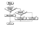
図16は、動き検出処理の詳細な処理手順を示すフローチャートである。この動き検出処理では、動き検出部15は、現フレーム画像と直前フレーム画像との間で動き検出を行い(ステップd1)、直前フレーム間検出結果を動き検出部15のRAMに一時的に記憶するとともに(ステップd3)、現フレーム画像と基準フレーム画像との間で動き検出を行い(ステップd5)、基準フレーム間検出結果を動き検出部15のRAMに一時的に記憶する(ステップd7)。続いて、信頼度評価部151が、直前フレーム間検出結果および基準フレーム間検出結果の信頼度を算出してその評価を行う(ステップd8)。ここでの評価の結果、信頼度評価部151が基準フレーム間検出結果を信頼性有りと判定した場合には(ステップd9:Yes)、続いて移動量決定部153が、現時点での基準移動量と今回の基準フレーム間検出結果との合計値を画像移動量として決定する(ステップd11)。そして、動き検出エリア設定部155が、ステップd11で決定された画像移動量に従って、基準フレームの基準フレーム間検出エリア内に配置された代表点に対する現フレーム画像中の探索範囲の設定位置を更新し(ステップd13)、図14のステップb19にリターンする。
FIG. 16 is a flowchart showing a detailed processing procedure of the motion detection process. In this motion detection process, the
一方、ステップd8での評価の結果、信頼度評価部151が基準フレーム間検出結果を信頼性無しと判定した場合には(ステップd9:No)、基準フレーム間検出結果についての信頼度の評価結果を判定する。信頼度評価部151が直前フレーム間検出結果を信頼性有りと判定した場合には(ステップd15:Yes)、続いて移動量決定部153が、画像移動量の前回値と今回の直前フレーム間検出結果との合計値を画像移動量として決定する(ステップd17)。決定後、ステップd23に移行する。一方、信頼度評価部151が直前フレーム間検出結果を信頼性無しと判定した場合であれば(ステップd15:No)、移動量決定部153は、動き量推定処理を行って、現フレーム画像と直前フレーム画像との間の動き量を推定する(ステップd19)。例えば、直近の所定数フレーム分の直前フレーム間検出結果を動き検出部15のRAMに保持しておくようにする。そして、この所定数の直前フレーム間検出結果をもとに、例えばこれらの平均値を求める等し、現フレーム画像と直前フレーム画像との間の推定動き量とする。そして、移動量決定部153は、画像移動量の前回値と推定動き量との合計値を画像移動量として決定する(ステップd21)。決定後、ステップd23に移行する。
On the other hand, as a result of the evaluation at step d8, when the
ステップd23では、動き検出エリア設定部155が、現フレームを基準フレームに再設定し、続いて基準フレームの基準フレーム間検出エリア内に配置された代表点に対する現フレーム画像中の探索範囲の設定位置を初期位置とするとともに(ステップd25)、基準移動量を現在の画像移動量の値に更新する(ステップd27)。その後、図14のステップb19にリターンする。
In step d23, the motion detection
以上説明したように、本実施の形態によれば、直前フレーム間の動き検出と基準フレーム間の動き検出とを行い、基準フレーム間検出結果に信頼性が有る場合には、この基準フレーム間検出結果を用いて基準フレームから現フレームまでの画像移動量を決定することができる。一方、基準フレーム間検出結果に信頼性が無い場合、直前フレーム間検出結果に信頼性があれば、この直前フレーム間検出結果を用いて画像移動量を決定することができる。また、基準フレーム間検出結果および直前フレーム間検出結果の双方に信頼性がなければ、直前フレーム間の動きを推定することによって画像移動量を決定することができる。すなわち、基準フレーム間検出結果に信頼性が有る間は、現フレーム画像と基準フレーム画像との間の動き検出によって画像移動量を決定するので、動き検出で生じた検出誤差が積算されることがない。また、基準フレーム間検出結果に信頼性が無いと判定された場合、直前フレーム間検出結果に信頼性が有れば、この直前フレーム間検出結果と画像移動量の前回値とから画像移動量を決定することができる。したがって、画像間の動き検出誤差を低減することができるため、画像の移動量を精度良く決定できるという効果を奏する。これによれば、パノラマ画像を合成する際、部分画像間を適切に繋ぎ合せて違和感のない自然なパノラマ画像を生成することができる。 As described above, according to the present embodiment, the motion detection between the previous frames and the motion detection between the reference frames are performed, and when the detection result between the reference frames is reliable, the detection between the reference frames is performed. The result can be used to determine the amount of image movement from the reference frame to the current frame. On the other hand, when the reference inter-frame detection result is not reliable, if the previous inter-frame detection result is reliable, the image movement amount can be determined using the previous inter-frame detection result. If both the reference inter-frame detection result and the previous inter-frame detection result are not reliable, the image movement amount can be determined by estimating the motion between the previous frames. In other words, while the detection result between the reference frames is reliable, the amount of image movement is determined by motion detection between the current frame image and the reference frame image, so that detection errors caused by motion detection may be integrated. Absent. If it is determined that the detection result between the reference frames is not reliable, if the detection result between the previous frames is reliable, the image movement amount is calculated from the detection result between the immediately preceding frames and the previous value of the image movement amount. Can be determined. Therefore, since the motion detection error between images can be reduced, there is an effect that the moving amount of the image can be determined with high accuracy. According to this, when synthesizing panoramic images, it is possible to appropriately connect the partial images and generate a natural panoramic image without a sense of incongruity.
以上、本発明の好適な実施の形態について説明したが、本発明は、上記したものに限定されず、発明の趣旨を逸脱しない範囲で適宜変更が可能である。 The preferred embodiment of the present invention has been described above, but the present invention is not limited to the above-described embodiment, and can be appropriately changed without departing from the spirit of the invention.
例えば、上記した実施の形態では、基準フレーム間検出結果が信頼性有りと判定された場合に、この基準フレーム間検出結果を用いて画像移動量を決定する場合について説明したが、これに限定されるものではない。図17は、変形例における動き検出処理の処理手順を示すフローチャートである。なお、図17において、図16と同様のステップには同一の符号を付する。また、以下の説明において、上記した実施の形態と同様の構成については、同一の符号を付する。 For example, in the above-described embodiment, the case where the image movement amount is determined using the reference interframe detection result when the reference interframe detection result is determined to be reliable has been described. However, the present invention is not limited to this. It is not something. FIG. 17 is a flowchart illustrating a procedure of motion detection processing according to the modification. In FIG. 17, the same steps as those in FIG. 16 are denoted by the same reference numerals. Moreover, in the following description, the same code | symbol is attached | subjected about the structure similar to above-described embodiment.
本変形例では、図17に示すように、信頼度評価部151が基準フレーム間検出結果を信頼性有りと判定した場合に(ステップd9:Yes)、続いて直前フレーム間検出結果の評価結果を判定する。そして、信頼性が有る場合には(ステップe29:Yes)、移動量決定部153が、重み付き移動量算出処理を行う(ステップe31)。例えば、移動量決定部153は、次式(1)に従って重み付き移動量Mwを算出する。ここで、Mbは今回の直前フレーム間検出結果、Mdは今回の基準フレーム間検出結果、Meは前回の基準フレーム間検出結果、Cbは今回の直前フレーム間検出結果の信頼度、Cdは今回の基準フレーム間検出結果の信頼度をそれぞれ示している。
Mw=Mb×Cb/(Cb+Cd)+(Md-Me)×Cd/(Cb+Cd)・・・(1)
In this modification, as shown in FIG. 17, when the
Mw = Mb × Cb / (Cb + Cd) + (Md−Me) × Cd / (Cb + Cd) (1)
そして、移動量決定部153は、基準移動量とステップe31で算出された重み付き移動量Mwとの合計値を画像移動量として決定する(ステップe33)。その後、ステップd13に移行する。
Then, the movement
一方、直前フレーム間検出結果に信頼性が無い場合には(ステップe29:No)、ステップe35に移行し、移動量決定部153が、現時点での基準移動量と今回の基準フレーム間検出結果との合計値を画像移動量として決定する。その後、ステップd13に移行する。すなわち、動き検出エリア設定部155が、基準フレームの基準フレーム間検出エリア内に配置された代表点に対する現フレーム画像中の探索範囲の設定位置を更新する。
On the other hand, if the previous inter-frame detection result is not reliable (step e29: No), the process proceeds to step e35, and the movement
また、上記した実施の形態では、「右」または「左」のいずれかをパノラマ撮影方向とする場合について説明したが、左右以外の方向をパノラマ撮影方向とすることもできる。例えば、「上」または「下」をパノラマ撮影方向としたパノラマ撮影を行う場合には、図15に示した撮影方向判定処理において、画像移動量の垂直成分の絶対値を予め設定される所定の方向閾値と比較するように構成し、画像移動量の垂直成分の正負を判定して正の値であれば「上」、負の値であれば「下」としてパノラマ撮影方向を確定する。 In the embodiment described above, the case where either “right” or “left” is set as the panorama shooting direction has been described, but directions other than the left and right can also be set as the panorama shooting direction. For example, when performing panoramic shooting with “upper” or “lower” as the panoramic shooting direction, the absolute value of the vertical component of the image movement amount is set in advance in the shooting direction determination process shown in FIG. It is configured to compare with the direction threshold value, and the positive / negative of the vertical component of the image movement amount is determined, and if it is a positive value, the panorama shooting direction is determined as “up”, and if it is a negative value, “down”.
また、上記した実施の形態では、パノラマ撮影方向が“右”の場合には画角範囲の右端位置を初期位置として基準フレーム間検出エリアを設定し、パノラマ撮影方向が“左”の場合には画角範囲の左端位置を初期位置として基準フレーム間検出エリアを設定することとして説明したが、例えば画角範囲の中央を初期位置として設定することとしてもよい。また、「上」または「下」をパノラマ撮影方向としたパノラマ撮影を行う場合には、画角範囲の上端位置や下端位置を初期位置として基準フレーム間検出を設定することとしてもよい。 In the above embodiment, when the panoramic shooting direction is “right”, the reference inter-frame detection area is set with the right end position of the angle of view range as the initial position, and when the panoramic shooting direction is “left”. Although it has been described that the reference inter-frame detection area is set with the left end position of the view angle range as the initial position, for example, the center of the view angle range may be set as the initial position. Further, when performing panoramic shooting with “upper” or “lower” as the panoramic shooting direction, the detection between the reference frames may be set with the upper end position and the lower end position of the field angle range as the initial positions.
1 デジタルカメラ
2 カメラ本体
11 撮像光学系
12 撮像素子
13 AFE
14 フレームメモリ
141 現フレームデータ
143 直前フレームデータ
145 基準フレームデータ
15 動き検出部
151 信頼度評価部
153 移動量決定部
155 動き検出エリア設定部
16 画像処理部
17 記録媒体I/F
18 記録媒体保持部
19 記録媒体
20 ビデオエンコーダ
21 表示ドライバ
22 表示部
23 ビデオ信号出力端子
24 操作部
3 シャッターボタン
4 電源ボタン
25 RAM
26 ROM
27 コントローラ
271 撮影開始指示部
DESCRIPTION OF
14
DESCRIPTION OF
26 ROM
27 Controller 271 Shooting start instruction section
Claims (11)
前記撮像部によって撮像された前記画像データを所定のフレーム単位で切り換えて表示する表示部と、
前記現フレームの画像と前記現フレームと隣接する隣接フレームの画像との間の動きを検出する隣接フレーム間動き検出部と、
前記現フレームの画像と所定の基準フレームの画像との間の動きを検出する基準フレーム間動き検出部と、
前記隣接フレーム間動き検出部の検出結果および前記基準フレーム間動き検出部の検出結果をもとに、各検出結果についての信頼度を評価する信頼度評価部と、
前記信頼度評価部の評価結果をもとに、前記隣接フレーム間動き検出部の検出結果および/または前記基準フレーム間動き検出部の検出結果を用いて前記基準フレームから現フレームまでの画像移動量を決定する移動量決定部と、
前記移動量決定部によって決定される画像移動量をもとに前記撮影処理の開始を指示する撮影開始指示部と、
を備えることを特徴とする撮像装置。 An imaging apparatus that includes an imaging unit that captures an image of a subject and generates image data, and that performs a plurality of imaging processes to generate a plurality of captured images,
A display unit that switches and displays the image data captured by the imaging unit in predetermined frame units;
An inter-adjacent frame motion detector that detects motion between the current frame image and the adjacent frame image adjacent to the current frame;
A reference inter-frame motion detector that detects a motion between the current frame image and a predetermined reference frame image;
Based on the detection result of the inter-frame motion detection unit and the detection result of the reference inter-frame motion detection unit, a reliability evaluation unit that evaluates the reliability of each detection result;
Based on the evaluation result of the reliability evaluation unit, the amount of image movement from the reference frame to the current frame using the detection result of the motion detection unit between adjacent frames and / or the detection result of the motion detection unit between reference frames A movement amount determination unit for determining
A shooting start instruction unit for instructing start of the shooting process based on an image movement amount determined by the movement amount determination unit;
An imaging apparatus comprising:
前記撮影開始指示部は、前記移動目標マークが示す前記移動目標位置に前記移動マークが移動した場合に、前記撮影処理の開始を指示することを特徴とする請求項1に記載の撮像装置。 A display control unit that performs control to display on the current frame image a movement mark that moves according to the image movement amount determined by the movement amount determination unit and a movement target mark that indicates a movement target position of the movement mark; ,
The imaging apparatus according to claim 1, wherein the imaging start instruction unit instructs the start of the imaging process when the movement mark moves to the movement target position indicated by the movement target mark.
前記撮像部によって撮像された前記画像データを所定のフレーム単位で切り換えて表示する表示ステップと、
前記現フレームの画像と前記現フレームと隣接する隣接フレームの画像との間の動きを検出する隣接フレーム間動き検出ステップと、
前記現フレームの画像と所定の基準フレームの画像との間の動きを検出する基準フレーム間動き検出ステップと、
前記隣接フレーム間動き検出ステップでの検出結果および前記基準フレーム間動き検出ステップでの検出結果をもとに、各検出結果についての信頼度を評価する信頼度評価ステップと、
前記信頼度評価ステップでの評価結果をもとに、前記隣接フレーム間動き検出ステップでの検出結果および/または前記基準フレーム間動き検出ステップでの検出結果を用いて前記基準フレームから現フレームまでの画像移動量を決定する移動量決定ステップと、
前記移動量決定ステップで決定される画像移動量をもとに前記撮影処理の開始を指示する撮影開始指示ステップと、
を含むことを特徴とする撮像装置における撮像方法。 An imaging method in an imaging apparatus that includes an imaging unit that images a subject and generates image data, and that performs a plurality of imaging processes to generate a plurality of captured images,
A display step of switching and displaying the image data captured by the imaging unit in predetermined frame units;
A motion detection step between adjacent frames for detecting a motion between an image of the current frame and an image of an adjacent frame adjacent to the current frame;
A reference inter-frame motion detection step for detecting a motion between the current frame image and a predetermined reference frame image;
A reliability evaluation step for evaluating the reliability of each detection result based on the detection result in the motion detection step between adjacent frames and the detection result in the motion detection step between the reference frames;
Based on the evaluation result in the reliability evaluation step, the detection result in the inter-adjacent frame motion detection step and / or the detection result in the reference inter-frame motion detection step is used to determine from the reference frame to the current frame. A moving amount determining step for determining an image moving amount;
A shooting start instruction step for instructing the start of the shooting process based on the image movement amount determined in the movement amount determination step;
An imaging method for an imaging apparatus, comprising:
Priority Applications (1)
| Application Number | Priority Date | Filing Date | Title |
|---|---|---|---|
| JP2008128400A JP2009278432A (en) | 2008-05-15 | 2008-05-15 | Imaging apparatus, and imaging method in imaging apparatus |
Applications Claiming Priority (1)
| Application Number | Priority Date | Filing Date | Title |
|---|---|---|---|
| JP2008128400A JP2009278432A (en) | 2008-05-15 | 2008-05-15 | Imaging apparatus, and imaging method in imaging apparatus |
Publications (1)
| Publication Number | Publication Date |
|---|---|
| JP2009278432A true JP2009278432A (en) | 2009-11-26 |
Family
ID=41443430
Family Applications (1)
| Application Number | Title | Priority Date | Filing Date |
|---|---|---|---|
| JP2008128400A Pending JP2009278432A (en) | 2008-05-15 | 2008-05-15 | Imaging apparatus, and imaging method in imaging apparatus |
Country Status (1)
| Country | Link |
|---|---|
| JP (1) | JP2009278432A (en) |
Cited By (7)
| Publication number | Priority date | Publication date | Assignee | Title |
|---|---|---|---|---|
| JP2011188035A (en) * | 2010-03-04 | 2011-09-22 | Fujifilm Corp | Imaging device, panoramic image synthesis method, and program therefor |
| CN102263894A (en) * | 2010-03-25 | 2011-11-30 | 卡西欧计算机株式会社 | Imaging apparatus |
| WO2012132204A1 (en) | 2011-03-30 | 2012-10-04 | Necカシオモバイルコミュニケーションズ株式会社 | Imaging device, photographing guide displaying method for imaging device, and non-transitory computer readable medium |
| JP2012209775A (en) * | 2011-03-30 | 2012-10-25 | Casio Comput Co Ltd | Image capture device, image capture control method and program |
| JP2016213879A (en) * | 2011-01-31 | 2016-12-15 | サムスン エレクトロニクス カンパニー リミテッド | Photographing device for photographing panoramic image and panoramic photographing method of the same |
| JP2019041188A (en) * | 2017-08-23 | 2019-03-14 | キヤノン株式会社 | Image processing apparatus, imaging apparatus, control method of image processing apparatus, and program |
| US11025868B2 (en) | 2017-09-05 | 2021-06-01 | Sony Corporation | Imaging apparatus, reproducing apparatus, control method, and control system |
-
2008
- 2008-05-15 JP JP2008128400A patent/JP2009278432A/en active Pending
Cited By (11)
| Publication number | Priority date | Publication date | Assignee | Title |
|---|---|---|---|---|
| JP2011188035A (en) * | 2010-03-04 | 2011-09-22 | Fujifilm Corp | Imaging device, panoramic image synthesis method, and program therefor |
| CN102263894A (en) * | 2010-03-25 | 2011-11-30 | 卡西欧计算机株式会社 | Imaging apparatus |
| JP2016213879A (en) * | 2011-01-31 | 2016-12-15 | サムスン エレクトロニクス カンパニー リミテッド | Photographing device for photographing panoramic image and panoramic photographing method of the same |
| US10498956B2 (en) | 2011-01-31 | 2019-12-03 | Samsung Electronics Co., Ltd. | Photographing apparatus for photographing panoramic image using visual elements on a display, and method thereof |
| US11025820B2 (en) | 2011-01-31 | 2021-06-01 | Samsung Electronics Co., Ltd. | Photographing apparatus for photographing panoramic image using visual elements on a display, and method thereof |
| US11317022B2 (en) | 2011-01-31 | 2022-04-26 | Samsung Electronics Co., Ltd. | Photographing apparatus for photographing panoramic image using visual elements on a display, and method thereof |
| WO2012132204A1 (en) | 2011-03-30 | 2012-10-04 | Necカシオモバイルコミュニケーションズ株式会社 | Imaging device, photographing guide displaying method for imaging device, and non-transitory computer readable medium |
| JP2012209775A (en) * | 2011-03-30 | 2012-10-25 | Casio Comput Co Ltd | Image capture device, image capture control method and program |
| US9549122B2 (en) | 2011-03-30 | 2017-01-17 | Nec Corporation | Imaging apparatus, photographing guide displaying method for imaging apparatus, and non-transitory computer readable medium |
| JP2019041188A (en) * | 2017-08-23 | 2019-03-14 | キヤノン株式会社 | Image processing apparatus, imaging apparatus, control method of image processing apparatus, and program |
| US11025868B2 (en) | 2017-09-05 | 2021-06-01 | Sony Corporation | Imaging apparatus, reproducing apparatus, control method, and control system |
Similar Documents
| Publication | Publication Date | Title |
|---|---|---|
| JP5144481B2 (en) | Imaging apparatus and imaging method | |
| JP4787180B2 (en) | Imaging apparatus and imaging method | |
| JP4697606B2 (en) | Imaging apparatus and focus control method | |
| JP2009232275A (en) | Image pickup device | |
| JP2009232276A (en) | Image pickup device | |
| JP6124700B2 (en) | IMAGING DEVICE, ITS CONTROL METHOD, PROGRAM, AND STORAGE MEDIUM | |
| JP2010041299A (en) | Electronic camera | |
| JP6116299B2 (en) | Imaging apparatus and control method thereof | |
| JP2009278432A (en) | Imaging apparatus, and imaging method in imaging apparatus | |
| JP5569361B2 (en) | Imaging apparatus and white balance control method | |
| JP2008042382A (en) | Imaging apparatus, display method and program | |
| JP2009278351A (en) | Imaging apparatus | |
| JP2010141609A (en) | Imaging apparatus | |
| JP2007116372A (en) | Digital camera | |
| JP2009017427A (en) | Imaging device | |
| JP5021370B2 (en) | Imaging apparatus, display method, and program | |
| JP6256298B2 (en) | IMAGING DEVICE, ITS CONTROL METHOD AND PROGRAM | |
| JP2009278350A (en) | Imaging apparatus, and imaging method in imaging apparatus | |
| JP2009139423A (en) | Imaging apparatus and subject distance calculating method | |
| JP2008283477A (en) | Image processor, and image processing method | |
| JP5289354B2 (en) | Imaging device | |
| JP4828486B2 (en) | Digital camera, photographing method and photographing program | |
| JP6399120B2 (en) | Imaging device | |
| JP2004117195A (en) | Digital camera with speed measuring function | |
| JP5142811B2 (en) | Imaging apparatus and imaging method in imaging apparatus |