JP2009272778A - Image transmission system and image transmission method - Google Patents
Image transmission system and image transmission method Download PDFInfo
- Publication number
- JP2009272778A JP2009272778A JP2008119984A JP2008119984A JP2009272778A JP 2009272778 A JP2009272778 A JP 2009272778A JP 2008119984 A JP2008119984 A JP 2008119984A JP 2008119984 A JP2008119984 A JP 2008119984A JP 2009272778 A JP2009272778 A JP 2009272778A
- Authority
- JP
- Japan
- Prior art keywords
- image data
- transmission
- divided
- transmitted
- still image
- Prior art date
- Legal status (The legal status is an assumption and is not a legal conclusion. Google has not performed a legal analysis and makes no representation as to the accuracy of the status listed.)
- Pending
Links
Images


Abstract
Description
本発明は、予め定められた動画データのフレーム伝送レートで静止画像データを伝送する画像伝送システム及び画像伝送方法に関する。 The present invention relates to an image transmission system and an image transmission method for transmitting still image data at a predetermined frame rate of moving image data.
従来、互いに通信可能に接続された機器同士で動画像データ/静止画像データを伝送する画像伝送システムが知られている。この画像伝送システムにおいて、互いに接続する機器としては、デジタルカメラ、デジタルビデオ、テレビ等の映像機器などがある。ここで、従来の画像伝送システムの構成例を図7を参照して説明する。 2. Description of the Related Art Conventionally, an image transmission system that transmits moving image data / still image data between devices that are communicably connected to each other is known. In this image transmission system, devices connected to each other include video devices such as digital cameras, digital videos, and televisions. Here, a configuration example of a conventional image transmission system will be described with reference to FIG.
図7に示すように、画像伝送システム100は、撮像装置110と表示装置120とが伝送路130により互いに通信可能に接続する構成である。撮像装置110では、制御部111の制御の下、撮像部112で撮像した動画像データ/静止画像データをメモリ113に格納する。このメモリ113に格納された動画像データ/静止画像データは、制御部111の制御の下、通信部114から伝送路130を介して表示装置120へ伝送される。表示装置120では、制御部121の制御の下、撮像装置110から伝送路130を介して伝送された動画像データ/静止画像データが通信部124で受信されてメモリ123に格納される。このメモリ123に格納された動画像データ/静止画像データは、制御部121の制御の下で読み出されて表示部122で表示される。
As shown in FIG. 7, the
上述した画像伝送システム100では、近年における映像機器の高画素化/高精細化に伴って、データの伝送レートを向上させる必要から、高速デジタルインターフェースが採用される場合がある。この高速デジタルインターフェースとしては、例えばHDMI(登録商標、High Definition Multimedia Interfaceの略)などが知られている。このHDMIでは、1920×1080画素という高画素の動画像データ/静止画像データを1秒間に60フレーム伝送する1080pなどの規格が定義されている。また、HDMIでは、DeepColorなどと称される仕様も定義されており、1画素あたりの輝度データ/色差データが従来それぞれ8ビットであったのに対して16ビット又はそれ以上のビット数まで拡張されている。特許文献1には、上述したHDMIなどの高速デジタル伝送路を用いて画像データを伝送する技術が開示されている。
上記従来技術では、画素数及び階調が増加するに従って、伝送路を通過する単位時間あたりのデータ量を増加させるために伝送路の信号帯域が高帯域化していた。また、従来技術では、この信号帯域が高帯域化することで、システムの消費電力量も増加していた。HDMI等の高速デジタルインターフェースにおける伝送規格では、静止画データを伝送する場合も、予め定められた動画データのフレーム伝送レートで送信する。例えば、8ビット/画素の動画データの伝送が1080i(1920×1080画素/フレーム、30フレーム/秒)で行われる場合であれば、8ビット/画素、1920×1080画素の1枚の静止画像データを伝送する場合も、そのフレーム伝送レートで伝送する。すなわち、1920×1080×30×8≒500Mbps程度の伝送レートで伝送する。同様に、動画データの伝送が1080p(60フレーム/秒)のDeepColor16ビット/画素で行われる場合であれば、同じ1枚の静止画像データを1920×1080×60×16≒2Gbps程度の伝送レートで伝送する。 In the above prior art, as the number of pixels and the gradation increase, the signal band of the transmission line is increased in order to increase the amount of data per unit time passing through the transmission line. Further, in the prior art, the power consumption of the system is increased by increasing the signal band. According to a transmission standard in a high-speed digital interface such as HDMI, even when still image data is transmitted, it is transmitted at a predetermined frame rate of moving image data. For example, if transmission of moving image data of 8 bits / pixel is performed at 1080i (1920 × 1080 pixels / frame, 30 frames / second), one still image data of 8 bits / pixel, 1920 × 1080 pixels Is transmitted at the frame transmission rate. That is, transmission is performed at a transmission rate of about 1920 × 1080 × 30 × 8≈500 Mbps. Similarly, if moving picture data is transmitted at 1080p (60 frames / second) DeepColor 16 bits / pixel, the same still image data is transmitted at a transmission rate of about 1920 × 1080 × 60 × 16≈2 Gbps. To transmit.
しかしながら、静止画像は動画と違って所定のフレームレートで表示させる必要がなく、予め定められた動画データのフレーム伝送レートで繰り返し1枚の静止画像データを伝送する必要はない。そのため、消費電力量が大きな高速伝送は不要であり、静止画像データの伝送時における省電力化が望まれていた。 However, unlike a moving image, it is not necessary to display a still image at a predetermined frame rate, and it is not necessary to repeatedly transmit one piece of still image data at a predetermined frame transmission rate of moving image data. Therefore, high-speed transmission with a large amount of power consumption is unnecessary, and power saving at the time of transmission of still image data has been desired.
本発明は、予め定められた動画のフレーム伝送レートで静止画像データが伝送される場合の、静止画像データ伝送時における省電力化を実現する画像伝送システム及び画像伝送方法を提供することを目的とする。 An object of the present invention is to provide an image transmission system and an image transmission method for realizing power saving at the time of still image data transmission when still image data is transmitted at a predetermined moving image frame transmission rate. To do.
上記目的は、互いに通信可能に接続された送信装置及び受信装置を有し、前記送信装置及び前記受信装置の間で、予め定められた動画データのフレーム伝送レートで静止画像データを伝送する画像伝送システムであって、前記送信装置は、伝送すべき個々の静止画像データを複数の分割画像データに分割する分割手段と、前記分割手段により分割された複数の分割画像データの夫々を、前記フレーム伝送レートで順次伝送する伝送手段と、を備え、前記受信装置は、前記送信装置から順次伝送された複数の分割画像データを合成し、前記個々の静止画像データを復元する合成手段を備えることを特徴とする本発明による画像伝送システムによって達成される。 An object of the present invention is to provide an image transmission that includes a transmission device and a reception device that are communicably connected to each other, and that transmits still image data between the transmission device and the reception device at a predetermined frame transmission rate of moving image data. In the system, the transmission device transmits each frame of the still image data to be transmitted into a plurality of divided image data and a plurality of divided image data divided by the dividing unit. Transmission means for sequentially transmitting at a rate, and the receiving apparatus includes combining means for combining a plurality of divided image data sequentially transmitted from the transmitting apparatus and restoring the individual still image data. This is achieved by the image transmission system according to the present invention.
また、上記目的は、互いに通信可能に接続された送信装置及び受信装置を有し、前記送信装置及び前記受信装置の間で、予め定められた動画データのフレーム伝送レートで静止画像データを伝送する画像伝送方法であって、伝送すべき個々の静止画像データを複数の分割画像データに分割する分割工程と、前記分割工程により分割された複数の分割画像データの夫々を、前記フレーム伝送レートで順次伝送する伝送工程と、前記伝送工程により順次伝送された複数の分割画像データを合成し、前記個々の静止画像データを復元する合成工程と、を有することを特徴とする本発明による画像伝送方法によっても達成される。 Also, the object is to have a transmission device and a reception device connected to be communicable with each other, and transmit still image data between the transmission device and the reception device at a predetermined frame rate of moving image data. An image transmission method, in which each of still image data to be transmitted is divided into a plurality of divided image data, and each of the plurality of divided image data divided by the dividing step is sequentially performed at the frame transmission rate. An image transmission method according to the present invention, comprising: a transmission step of transmitting; and a synthesis step of synthesizing a plurality of divided image data sequentially transmitted in the transmission step and restoring the individual still image data. Is also achieved.
このような構成により、本発明によれば、予め定められた動画のフレーム伝送レートで静止画像データが伝送される場合の、静止画像データ伝送時における省電力化を実現できる。 With such a configuration, according to the present invention, it is possible to realize power saving at the time of still image data transmission when still image data is transmitted at a predetermined moving image frame transmission rate.
以下、この発明の実施の形態について図を参照して説明するが、この発明は以下の実施の形態に限定されない。また、この発明の実施の形態は発明の最も好ましい形態を示すものであり、発明の範囲を限定するものではない。 Hereinafter, embodiments of the present invention will be described with reference to the drawings. However, the present invention is not limited to the following embodiments. Further, the embodiment of the present invention shows the most preferable mode of the invention, and does not limit the scope of the invention.
[第1実施形態]
先ず、本発明に係る第1実施形態について、図1〜図4を参照して説明する。ここで、図1は、第1実施形態に係る画像伝送システム1の構成を示すブロック図である。図2〜図4は画像分割の概要を示す概念図である。
[First Embodiment]
First, a first embodiment according to the present invention will be described with reference to FIGS. Here, FIG. 1 is a block diagram showing a configuration of the image transmission system 1 according to the first embodiment. 2 to 4 are conceptual diagrams showing an outline of image division.
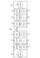
図1に示すように、画像伝送システム1は、撮像装置10と表示装置20とが伝送路Nにより互いに通信可能に接続する構成である。伝送路Nは、例えばHDMI規格でデータ伝送を行う通信ケーブルなどである。なお、伝送路Nは、前述したHDMI規格の通信ケーブル以外に、IEEE1394、USB、LAN、インターネットなどの有線ケーブルや、IEEE802.11a、802.11b、802.11g等の無線であってよく、特に限定しない。ここで、IEEEとは、Institute of Electrical and Electronic Engineersの略語である。また、USBとは、Universal Serial Busの略語である。また、LANとは、Local Area Networkの略語である。
As shown in FIG. 1, the image transmission system 1 is configured such that an
撮像装置10は、制御部11、撮像部12、メモリ13、画像分割部14、通信部15を備える。表示装置20は、制御部21、表示部22、メモリ23、画像合成部24、通信部25を備える。すなわち、撮像装置10は撮像した画像データを伝送路Nを介して伝送させる送信装置であり、表示装置20は伝送路Nを介して伝送された画像データを受信する受信装置である。
The
ここで、撮像装置10、表示装置20の内部構成について詳細に説明する。制御部11は、撮像装置10の動作を中央制御する。具体的には、制御部11は、CPU(Central Processing Unit)、RAM(Random Access Memory)、ROM(Read Only Memory)などを有する構成である。制御部11は、ROMなどに記憶されたプログラムデータをRAMの作業領域に展開し、その展開されたプログラムデータとCPUとの協働により各部を統括制御する。
Here, the internal configurations of the
撮像部12は、撮像レンズ及び結像した画像を光電変換するための撮像素子などを有し(いずれも図示しない)、被写体像を撮像した動画像データ/静止画像データを出力する。メモリ13は、揮発性メモリなどであり、撮像部12から出力された動画像データ/静止画像データを格納する。
The
画像分割部14は、制御部11の制御の下、メモリ13に格納された伝送すべき静止画像データをビット操作や読み出しラインを操作することで分割するDSP(Digital Signal Processor)などである。なお、画像分割部14における静止画像データの分割については詳細を後述する。
The
通信部15は、制御部11の制御の下、伝送路Nを介したデータ伝送を行うためのインターフェースなどを備える。例えば、通信部15は、伝送路NがHDMI規格でデータ伝送を行う通信ケーブルである場合、その通信ケーブルと接続するHDMIインターフェースである。通信部15は、伝送路Nを介したデータ伝送において、静止画像データを伝送する場合、予め定められた動画データのフレーム伝送レートで伝送する。例えば、通信部15は、HDMI規格の1080iでデータ伝送する場合、30フレーム/秒で1920×1080画素の画像データを伝送する。また、通信部15は、HDMI規格の1080pでデータ伝送する場合、60フレーム/秒で1920×1080画素の画像データを伝送する。なお、通信部15は、画像分割部14により静止画像データを分割した分割画像データを伝送する場合は、各分割画像データを上述した伝送レートで伝送する。すなわち、伝送路Nにおける静止画データの伝送では、予め定められた動画データのフレーム伝送レートで静止画像データを伝送しなければならないが、1フレームあたりのデータ量は変えても問題がない。この点に着目し、撮像装置10では、1枚の静止画像データを分割することでフレームあたりのデータ量を減らしている。従って、伝送路Nを介したデータ伝送の動作スピードを落とすことができ、通信部15における省電力化が実現できる。
The
撮像装置10と同様に、制御部21は、表示装置20の動作を中央制御する。表示部22は、制御部21の制御の下、メモリ23に格納された動画像データ/静止画像データを表示出力する表示画面を有する。具体的には、表示部22は、PDP、LCD、SEDなどを用いたものであってよい。ここで、PDPは、Plasma Display Panelの略語である。また、LCDは、Liquid Crystal Displayの略語である。また、SEDは、Surface-Conduction Electron-emitter Displayの略語である。メモリ23は、通信部25により受信された動画像データ/静止画像データを格納する揮発性メモリなどである。
Similar to the
画像合成部24は、制御部21の制御の下、通信部25により受信された画像データの中で、画像分割部14により分割された分割画像データを合成して静止画像データを取得するためのDSPなどである。この画像合成部24における画像合成は、前述した画像分割部14と逆のビット操作や読み出しライン操作を行うことで実現する。通信部25は、制御部21の制御の下、伝送路Nを介したデータ伝送を行うためのインターフェースなどを備える。例えば、通信部25は、伝送路NがHDMI規格でデータ伝送を行う通信ケーブルである場合、その通信ケーブルと接続するHDMIインターフェースである。通信部25は、伝送路Nを介して前述した伝送レートで伝送される動画像データ/静止画像データを受信して、メモリ23に一時記憶させる。
The
[上位ビット/下位ビットで静止画像データを分割]
次に、画像分割部14における伝送すべき静止画像データの分割について詳細に説明する。先ず、伝送すべき静止画像データについて、各画素の輝度データ/色差データを上位ビットと下位ビットで分割する場合について図2を参照して説明する。
[Split still image data by upper bit / lower bit]
Next, the division of still image data to be transmitted in the
図2に示すように、伝送すべき静止画像データG1は、画素P1、画素P2…であり、1画素が予め定められた複数ビットで表される輝度データ、色差データからなる画像データである。ここで、静止画像データG1は、HDMI規格の画像データであり、1080p、DeepColor16ビットの多ビット画像データとする。従って、例えば画素P1は、ビットB1〜B16の輝度データY1と、ビットb1〜b16の色差データCr1の、それぞれが16ビットの輝度データ、色差データからなる。
As shown in FIG. 2, the still image data G1 to be transmitted is pixel P1, pixel P2,..., And is image data composed of luminance data and color difference data in which one pixel is represented by a plurality of predetermined bits. The still image data G1 is HDMI standard image data, and is multi-bit image data of 1080p and
画像分割部14は、静止画像データG1における各画素の輝度データ、色差データを、ビット操作によりビット位置が上位ビット又は下位ビットで分割する。すなわち、画像分割部14は、1画素が予め定められた複数ビットで表される多ビット画像データをビット単位で分割する。また、その多ビット画像データの分割は、複数ビットの上位ビットから構成される分割画像データと、複数ビットから上位ビットを除いた下位ビットから構成される分割画像データとに分割する。具体的には、画像分割部14は、静止画像データG1を、上位ビットの輝度データ、色差データで構成される分割画像データG1a、下位ビットの輝度データ、色差データで構成される分割画像データG1bに分割する。
The
より具体的には、画像分割部14は、上述した輝度データY1についてビット操作を行うことで、上位ビット(例えばビットB1〜B8)からなる輝度データY1aと、下位ビット(例えばビットB8〜B16)からなる輝度データY1bへ分割する。同様に、画像分割部14は、色差データCr1についてビット操作を行うことで、上位ビット(例えばビットb1〜b8)からなる色差データCr1aと、下位ビット(例えばビットb8〜b16)からなる色差データCr1bへ分割する。この分割により、分割画像データG1aは、上位ビットの輝度データY1aと色差データCr1aを画素P1a、同様に上位ビットの画素P2a…(以下の画素も同様)…とする画像データである。同様に、分割画像データG1bは、下位ビットの輝度データY1bと色差データCr1bを画素P1b、同様に下位ビットの画素P2b…(以下の画素も同様)…とする画像データである。
More specifically, the
[奇数ビット/偶数ビットで静止画像データを分割]
次に、伝送すべき静止画像データについて、各画素の輝度データ/色差データを奇数ビットと偶数ビットで分割する場合について図3を参照して説明する。なお、前述した上位ビットと下位ビットで分割する場合と同一の構成については、同一の符号を付して説明を省略する。
[Dividing still image data by odd / even bits]
Next, with regard to still image data to be transmitted, a case where luminance data / color difference data of each pixel is divided into odd bits and even bits will be described with reference to FIG. In addition, about the same structure as the case where it divides | segments by the upper bit and lower bit mentioned above, the same code | symbol is attached | subjected and description is abbreviate | omitted.
図3に示すように、画像分割部14は、静止画像データG1における各画素の輝度データ、色差データを、ビット操作により奇数ビット又は偶数ビットで分割する。すなわち、画像分割部14は、静止画像データG1を、奇数ビットの輝度データ、色差データで構成される分割画像データG1c、偶数ビットの輝度データ、色差データで構成される分割画像データG1dに分割する。
As shown in FIG. 3, the
具体的には、画像分割部14は、輝度データY1についてビット操作を行うことで、奇数ビット(例えば、ビットB1、…、B15)からなる輝度データY1cと、偶数ビット(例えばビットB2、…、B16)からなる輝度データY1dへ分割する。同様に、画像分割部14は、色差データCr1についてビット操作を行うことで、奇数ビット(例えばビットb1、…、b15)からなる色差データCr1cと、偶数ビット(例えばビットb2、…、b16)からなる色差データCr1dへ分割する。この分割により、分割画像データG1cは、奇数ビットの輝度データY1cと色差データCr1cを画素P1c、同様に奇数ビットの画素P2c…(以下の画素も同様)…とする画像データである。同様に、分割画像データG1dは、偶数ビットの輝度データY1dと色差データCr1dを画素P1d、同様に偶数ビットの画素P2d…(以下の画素も同様)とする画像データである。
Specifically, the
[奇数フィールド/偶数フィールドで静止画像データを分割]
次に、伝送すべき静止画像データについて、その静止画像データに基づいた静止画像をインタレース方式で表示するためのフィールドに分割する場合について、図4を参照して説明する。なお、前述した分割例と同一の構成については、同一の符号を付して説明を省略する。
[Dividing still image data in odd / even fields]
Next, with respect to still image data to be transmitted, a case where a still image based on the still image data is divided into fields for display in an interlaced manner will be described with reference to FIG. In addition, about the structure same as the division example mentioned above, the same code | symbol is attached | subjected and description is abbreviate | omitted.
図4に示すように、画像分割部14は、メモリ13に記憶された伝送すべき静止画像データG1の読み出し対象ラインを操作するなどして、奇数ラインの読み出しによる分割画像データG1e、偶数ラインの読み出しによる分割画像データG1fを生成する。すなわち、分割画像データG1eは、静止画像データG1の奇数ラインであるラインL1、L3…(以下のラインも同様)…のインタレース方式で表示するためのフィールド画像である。また、分割画像データG1fは、静止画像データG1の偶数ラインであるラインL2、L4…(以下のラインも同様)…のインタレース方式で表示するためのフィールド画像である。
As shown in FIG. 4, the
次に、画像伝送システム1における静止画像データを伝送する際の動作であって、制御部11が制御して行う撮像装置10の動作、制御部21が制御して行う表示装置20の動作について詳細に説明する。画像伝送システム1では、撮像装置10で撮像した静止画像データを表示装置20で表示再生させるなどの、操作部(特に図示しない)からの操作指示などに基づいて、撮像装置10から表示装置20への静止画像データの伝送を開始する。撮像装置10では、メモリ13に格納された伝送すべき静止画像データを表示装置20へ伝送する際に、画像分割部14においてその静止画像データを分割した分割画像データを生成する。なお、画像分割部14において前述した何れの分割を行うかについては、ROMなどで予め設定されていてよい。又は、表示装置20との接続開始時や、画像データの伝送開始時などにおいて、分割の種別を示すデータを互いに伝送して設定してもよい。次いで、制御部11の制御の下、画像分割部14により生成された分割画像データの夫々は、予め定められた動画データのフレーム伝送レートで、通信部15により伝送路Nを介して表示装置20へ順次伝送される。
Next, operations for transmitting still image data in the image transmission system 1, which are operations of the
表示装置20では、伝送路Nを介して伝送された分割画像データを通信部25により受信し、メモリ23へ一時記憶する。次いで、表示装置20では、画像合成部24においてメモリ23に記憶された分割画像データを合成することで、撮像装置10から伝送された静止画像データを取得する。この画像合成部24において、何れの分割方法で分割された画像を合成するかについては、前述した画像分割部14と同様、ROMなどに予め設定されていてよい。又は、撮像装置10との接続開始時や、画像データの伝送開始時などに分割の種別を示すデータを互いに伝送して設定してもよい。次いで、表示装置20では、合成した静止画像データを表示部22により表示出力する。
In the
以上のように、画像伝送システム1は、互いに通信可能に接続された送信装置である撮像装置10及び受信装置である表示装置20を有し、撮像装置10及び表示装置20の間で、予め定められた動画データのフレーム伝送レートで静止画像データを伝送する。撮像装置10は、伝送すべき個々の静止画像データを複数の分割画像データに分割する分割手段としての画像分割部14を備える。また、撮像装置10は、画像分割部14により分割された複数の分割画像データの夫々を、動画データのフレーム伝送レートで順次伝送する伝送手段としての通信部15を備える。また、表示装置20は、撮像装置10から順次伝送された複数の分割画像データを合成し、伝送すべき個々の静止画像データを復元する合成手段としての画像合成部24を備える。従って、画像伝送システム1は、予め定められた動画のフレーム伝送レートで静止画像データが伝送される場合の、静止画像データ伝送時におけるデータ伝送レートを低減させることができる。よって、画像伝送システム1は、消費電力量が大きな高速伝送が不要となり、静止画像データの伝送時における省電力化を実現できる。
As described above, the image transmission system 1 includes the
[第2実施形態]
次に、本発明に係る第2実施形態について、図5を参照して説明する。ここで、図5は、第2実施形態に係る画像伝送システム1aの構成を示すブロック図である。なお、前述した第1実施形態と同一の構成については同一の符号を付して説明を省略する。
[Second Embodiment]
Next, a second embodiment according to the present invention will be described with reference to FIG. Here, FIG. 5 is a block diagram showing a configuration of an
図5に示すように、画像伝送システム1aは、撮像装置10aと表示装置20aとが伝送路Nにより互いに通信可能に接続する構成である。ここで、伝送路Nは、HDMI規格でデータ伝送を行う通信ケーブルとする。撮像装置10aは前述した構成のほかに判定回路16を備え、表示装置20aは前述した構成のほかに判定回路26、ROM27を備える構成である。
As shown in FIG. 5, the
判定回路16は、HDMI規格に従って表示装置20aから送信された機器情報に基づいて、その表示装置20aが前述した分割画像データを合成する画像合成部24を備え、表示装置20aが分割画像データを合成可能か否かを判定する回路部である。判定回路26は、HDMI規格に従って撮像装置10aから送信された静止画像データの付帯情報を読み取ることで、その送信された静止画像データが前述した分割画像データであるか否かを判定する回路部である。ROM27は、静止画像データを分割した分割画像データを合成するための画像合成部24を備えるか否かなど、表示装置20aにおける分割画像データの合成の可否を示す情報を含む機種情報を格納する。
The
次に、画像伝送システム1aにおける静止画像データを伝送する際の動作であって、制御部11が制御して行う撮像装置10aの動作、制御部21が制御して行う表示装置20aの動作について詳細に説明する。先ず、画像伝送システム1では、撮像装置10aと表示装置20aとの間でHDMIによる通信接続が確立された際に、EDID(Extended Display Identification Data)の読み出しなどの機器認証が行われる。具体的には、ROM27に格納された機種情報が読み出されて撮像装置10aへ伝送される。撮像装置10aでは、表示装置20aから送信された機種情報に基づいて、表示装置20aが分割画像データを合成可能か否かを判定回路16で判定する。次いで、撮像装置10aでは、判定回路16による判定が合成可能である場合に、画像分割部14において伝送すべき静止画像データを分割するように制御部11が制御する。
Next, operations for transmitting still image data in the
次いで、画像伝送システム1aでは、撮像装置10aで撮像した静止画像データを表示装置20aで表示再生させるなどの、操作部からの操作指示などに基づいて、撮像装置10aから表示装置20aへの静止画像データの伝送を開始する。具体的には、撮像装置10aは、制御部11の制御の下、判定回路16における判定結果による静止画像データ又は分割画像データを、予め定められた動画データのフレーム伝送レートで通信部15から表示装置20aへ順次伝送する。なお、制御部11は、分割画像データを通信部15から伝送する場合、HDMI規格に従った画像データの付帯情報であるINFO FRAMEに、分割画像データであることを示す情報(フラグなど)を付帯させて伝送するように制御する。
Next, in the
表示装置20aでは、伝送路Nを介して伝送された静止画像データ又は分割画像データを通信部25により受信し、メモリ23へ一時記憶する。次いで、表示装置20aでは、受信した画像データの付帯情報を読み出し、送信された静止画像データが分割画像データであるか否かを判定回路26で判定する。表示装置20aでは、制御部21の制御の下、判定回路26による判定結果が分割画像データである場合に、メモリ23に一時記憶された画像データが画像合成部24により合成される。次いで、表示装置20aでは、受信した静止画像データ又は合成後の静止画像データを表示部22により表示出力する。
In the
以上のように、撮像装置10aは、表示装置20aから送信された機器情報に基づいて、表示装置20aが分割画像データを合成可能か否かを判定する第1判定手段としての判定回路16を更に備える。また、撮像装置10aは、判定回路16による判定結果が合成可能である場合に伝送すべき静止画像データの分割を行う。従って、画像伝送システム1aは、表示装置20aが分割画像データの合成に対応している場合にのみ、静止画像データを分割して伝送することができ、機種に応じた静止画像データの分割伝送を可能とすることができる。
As described above, the
また、撮像装置10aの通信部15は、分割された複数の分割画像データの夫々を順次伝送する際に、分割画像データであることを示す付帯情報を、分割画像データに付帯して伝送する。表示装置20aは、撮像装置10aから伝送された付帯情報に基づいて、撮像装置10から伝送された画像データが分割画像データであるか否かを判定する第2判定手段としての判定回路26を更に備える。また、表示装置20aでは、制御部21の制御の下、判定回路26による判定結果が分割画像データである場合に画像合成部24による合成を行う。従って、画像伝送システム1aは、静止画像データが分割されて伝送された場合に応じてその分割画像データの合成を行うことができる。
In addition, when the
[第3実施形態]
次に、本実施の形態に係る第3実施形態について、図6を参照して説明する。ここで、図6は、第3実施形態に係る画像伝送システム1bの構成を示すブロック図である。なお、前述した第1、2実施形態と同一の構成については同一の符号を付して説明を省略する。
[Third Embodiment]
Next, a third embodiment according to the present embodiment will be described with reference to FIG. Here, FIG. 6 is a block diagram showing a configuration of an image transmission system 1b according to the third embodiment. In addition, about the structure same as 1st, 2nd embodiment mentioned above, the same code | symbol is attached | subjected and description is abbreviate | omitted.
図6に示すように、画像伝送システム1bは、撮像装置10bと表示装置20bとが伝送路Nにより互いに通信可能に接続する構成である。ここで、伝送路Nは、HDMI規格でデータ伝送を行う通信ケーブルとする。撮像装置10bは、前述した構成のほかにCEC送受信部18、判定回路19を備え、表示装置20bは前述した構成のほかにCEC送受信部28、判定回路29を備える構成である。
As shown in FIG. 6, the image transmission system 1 b has a configuration in which an
CEC送受信部18、28は、制御部の制御の下、通信部においてHDMIに従ったCEC(Consumer Electronics Control)を送受信するための回路部である。すなわち、CEC送受信部18、28は、互いに接続する機器間において、制御情報の伝送を行う。判定回路19、29は、制御部の制御の下、上述した制御情報に含まれる内容を判定する回路部である。具体的には、判定回路19、29は、分割画像データの伝送を示す制御情報であるか否かを判定する。
The CEC transmission /
次に、画像伝送システム1bにおける静止画像データを伝送する際の動作であって、制御部11が制御して行う撮像装置10bの動作、制御部21が制御して行う表示装置20bの動作について詳細に説明する。先ず、画像伝送システム1bでは、撮像装置10bで撮像した静止画像データを表示装置20bで表示再生させるなどの、操作部からの操作指示などに基づいて、撮像装置10bから表示装置20bへの静止画像データの伝送を開始する。撮像装置10bでは、メモリ13に格納された伝送すべき静止画像データを表示装置20bへ伝送する際に、画像分割部14においてその静止画像データを分割した分割画像データを生成する。次いで、制御部11の制御の下、画像分割部14により生成された分割画像データの夫々は、通信部15により伝送路Nを介して予め定められた動画データのフレーム伝送レートで表示装置20へ順次伝送される。なお、制御部11は、分割画像データを順次伝送する際に、分割画像データの伝送を示す制御情報をCEC送受信部18より表示装置20bへ伝送するように制御する。
Next, the operation when transmitting still image data in the image transmission system 1b, the operation of the
表示装置20bでは、伝送路Nを介して伝送された分割画像データを通信部25により受信し、メモリ23へ一時記憶する。次いで、表示装置20bでは、受信した制御情報が分割画像データの伝送を示す制御情報であるか否かを判定回路29により判定する。表示装置20bでは、制御部21の制御の下、29による判定結果が分割画像データの伝送である場合、その制御情報とともに受信してメモリ23に一時記憶された画像データが画像合成部24により合成される。次いで、表示装置20bでは、受信した静止画像データを表示部22により表示出力する。
In the
以上のように、撮像装置10b及び表示装置20bは、互いに制御情報を伝送する制御情報伝送手段としてのCEC送受信部18、28を備える。また、撮像装置10bのCEC送受信部18は、画像分割部14により分割された複数の分割画像データの夫々を順次伝送する際に、分割画像データであることを示す制御情報を表示装置20bへ伝送する。また、表示装置20bは、制御部21の制御の下、分割画像データであることを示す制御情報とともに受信した画像データについて画像合成部24による合成を行う。従って、画像伝送システム1bでは、静止画像データの分割に応じて送信される制御情報により、分割画像データの合成を行うことができる。
As described above, the
なお、上述した実施形態における記述は、一例を示すものであり、これに限定するものではない。上述した実施の形態における構成及び動作に関しては適宜変更が可能である。例えば、上述した実施形態では、送信装置が撮像装置、受信装置が表示装置の場合を例示したが、予め定められた動画データのフレーム伝送レートで静止画像データを伝送する機器同士が接続する構成であれば、いずれであってもよい。具体的には、画像データが記録された記録媒体から画像データを読み出す機器と、その読み出された画像データを再生する機器とが接続する構成などであってよい。 Note that the description in the above-described embodiment shows an example, and the present invention is not limited to this. The configuration and operation in the above-described embodiment can be changed as appropriate. For example, in the above-described embodiment, the case where the transmission device is an imaging device and the reception device is a display device is illustrated. However, devices that transmit still image data at a predetermined frame transmission rate of moving image data are connected to each other. Any of them may be used. Specifically, a configuration in which a device that reads image data from a recording medium on which the image data is recorded and a device that reproduces the read image data may be connected.
(他の実施形態)
上述の実施形態は、システム或は装置のコンピュータ(或いはCPU、MPU等)によりソフトウェア的に実現することも可能である。従って、上述の実施形態をコンピュータで実現するために、該コンピュータに供給されるコンピュータプログラム自体も本発明を実現するものである。つまり、上述の実施形態の機能を実現するためのコンピュータプログラム自体も本発明の一つである。
(Other embodiments)
The above-described embodiment can also be realized in software by a computer of a system or apparatus (or CPU, MPU, etc.). Therefore, the computer program itself supplied to the computer in order to implement the above-described embodiment by the computer also realizes the present invention. That is, the computer program itself for realizing the functions of the above-described embodiments is also one aspect of the present invention.
なお、上述の実施形態を実現するためのコンピュータプログラムは、コンピュータで読み取り可能であれば、どのような形態であってもよい。例えば、オブジェクトコード、インタプリタにより実行されるプログラム、OSに供給するスクリプトデータ等で構成することができるが、これらに限るものではない。上述の実施形態を実現するためのコンピュータプログラムは、記憶媒体又は有線/無線通信によりコンピュータに供給される。プログラムを供給するための記憶媒体としては、例えば、フレキシブルディスク、ハードディスク、磁気テープ等の磁気記憶媒体、MO、CD、DVD等の光/光磁気記憶媒体、不揮発性の半導体メモリなどがある。 The computer program for realizing the above-described embodiment may be in any form as long as it can be read by a computer. For example, it can be composed of object code, a program executed by an interpreter, script data supplied to the OS, but is not limited thereto. A computer program for realizing the above-described embodiment is supplied to a computer via a storage medium or wired / wireless communication. Examples of the storage medium for supplying the program include a magnetic storage medium such as a flexible disk, a hard disk, and a magnetic tape, an optical / magneto-optical storage medium such as an MO, CD, and DVD, and a nonvolatile semiconductor memory.
有線/無線通信を用いたコンピュータプログラムの供給方法としては、コンピュータネットワーク上のサーバを利用する方法がある。この場合、本発明を形成するコンピュータプログラムとなりうるデータファイル(プログラムファイル)をサーバに記憶しておく。プログラムファイルとしては、実行形式のものであっても、ソースコードであっても良い。そして、このサーバにアクセスしたクライアントコンピュータに、プログラムファイルをダウンロードすることによって供給する。この場合、プログラムファイルを複数のセグメントファイルに分割し、セグメントファイルを異なるサーバに分散して配置することも可能である。つまり、上述の実施形態を実現するためのプログラムファイルをクライアントコンピュータに提供するサーバ装置も本発明の一つである。 As a computer program supply method using wired / wireless communication, there is a method of using a server on a computer network. In this case, a data file (program file) that can be a computer program forming the present invention is stored in the server. The program file may be an executable format or a source code. Then, the program file is supplied by downloading to a client computer that has accessed the server. In this case, the program file can be divided into a plurality of segment files, and the segment files can be distributed and arranged on different servers. That is, a server apparatus that provides a client computer with a program file for realizing the above-described embodiment is also one aspect of the present invention.
また、上述の実施形態を実現するためのコンピュータプログラムを暗号化して格納した記憶媒体を配布し、所定の条件を満たしたユーザに、暗号化を解く鍵情報を供給し、ユーザの有するコンピュータへのインストールを許可してもよい。鍵情報は、例えばインターネットを介してホームページからダウンロードさせることによって供給することができる。また、上述の実施形態を実現するためのコンピュータプログラムは、すでにコンピュータ上で稼働するOSの機能を利用するものであってもよい。さらに、上述の実施形態を実現するためのコンピュータプログラムは、その一部をコンピュータに装着される拡張ボード等のファームウェアで構成してもよいし、拡張ボード等が備えるCPUで実行するようにしてもよい。 In addition, a storage medium in which the computer program for realizing the above-described embodiment is encrypted and distributed is distributed, and key information for decrypting is supplied to a user who satisfies a predetermined condition, and the user's computer Installation may be allowed. The key information can be supplied by being downloaded from a homepage via the Internet, for example. Further, the computer program for realizing the above-described embodiment may use an OS function already running on the computer. Further, a part of the computer program for realizing the above-described embodiment may be configured by firmware such as an expansion board attached to the computer, or may be executed by a CPU provided in the expansion board. Good.
1、1a、1b 画像伝送システム
10、10a、10b 撮像装置
11 制御部
12 撮像部
13 メモリ
14 画像分割部
15 通信部
16、19 判定回路
18 CEC送受信部
20、20a、20b 表示装置
21 制御部
22 表示部
23 メモリ
24 画像合成部
25 通信部
26、29 判定回路
27 ROM
28 CEC送受信部
N 伝送路
DESCRIPTION OF
28 CEC transceiver N Transmission path
Claims (12)
前記送信装置は、
伝送すべき個々の静止画像データを複数の分割画像データに分割する分割手段と、
前記分割手段により分割された複数の分割画像データの夫々を、前記フレーム伝送レートで順次伝送する伝送手段と、
を備え、
前記受信装置は、
前記送信装置から順次伝送された複数の分割画像データを合成し、前記個々の静止画像データを復元する合成手段を備えることを特徴とする画像伝送システム。 An image transmission system having a transmission device and a reception device connected to be communicable with each other, and transmitting still image data between the transmission device and the reception device at a predetermined frame transmission rate of moving image data. ,
The transmitter is
Dividing means for dividing individual still image data to be transmitted into a plurality of divided image data;
Transmission means for sequentially transmitting each of a plurality of divided image data divided by the dividing means at the frame transmission rate;
With
The receiving device is:
An image transmission system comprising: a combining unit that combines a plurality of divided image data sequentially transmitted from the transmission device and restores the individual still image data.
前記分割手段は、前記伝送すべき静止画像データを、ビット単位で分割することを特徴とする請求項1に記載の画像伝送システム。 The still image data is multi-bit image data in which one pixel is represented by a plurality of predetermined bits,
The image transmission system according to claim 1, wherein the dividing unit divides the still image data to be transmitted in bit units.
前記分割手段は、前記第1判定手段による判定結果が合成可能である場合に前記伝送すべき静止画像データの分割を行うことを特徴とする請求項1乃至5のいずれか一項に記載の画像伝送システム。 The transmission device further includes first determination means for determining whether the reception device can synthesize the divided image data based on the device information transmitted from the reception device,
The image according to any one of claims 1 to 5, wherein the dividing unit divides the still image data to be transmitted when the determination result by the first determining unit can be combined. Transmission system.
前記受信装置は、前記付帯情報に基づいて、前記送信装置から伝送された画像データが前記分割画像データであるか否かを判定する第2判定手段を更に備え、
前記合成手段は、前記送信装置から伝送された画像データが前記第2判定手段によって前記分割画像データと判定された場合に前記合成を行うことを特徴とする請求項1乃至6のいずれか一項に記載の画像伝送システム。 The transmission means attaches supplementary information indicating that it is divided image data to the divided image data when sequentially transmitting each of the plurality of divided image data divided by the dividing means to the receiving device. Transmit
The receiving device further includes second determining means for determining whether the image data transmitted from the transmitting device is the divided image data based on the incidental information,
7. The composition unit according to claim 1, wherein the composition unit performs the composition when the image data transmitted from the transmission device is determined to be the divided image data by the second determination unit. The image transmission system described in 1.
前記制御情報伝送手段は、前記分割手段により分割された複数の分割画像データの夫々を前記受信装置に順次伝送する際に、前記分割画像データであることを示す制御情報を前記受信装置へ伝送し、
前記合成手段は、前記送信装置から分割画像データであることを示す制御情報とともに受信した画像データについて、前記合成を行うことを特徴とする請求項1乃至7のいずれか一項に記載の画像伝送システム。 The transmission device further comprises control information transmission means for transmitting control information to the reception device,
The control information transmitting means transmits control information indicating the divided image data to the receiving apparatus when sequentially transmitting each of the plurality of divided image data divided by the dividing means to the receiving apparatus. ,
8. The image transmission according to claim 1, wherein the synthesizing unit performs the synthesis on image data received together with control information indicating that the image data is divided image data from the transmission device. 9. system.
伝送すべき個々の静止画像データを複数の分割画像データに分割する分割手段と、
前記分割手段により分割された複数の分割画像データの夫々を、前記フレーム伝送レートで順次伝送する伝送手段と、
を備えることを特徴とする送信装置。 A transmission device that transmits still image data at a predetermined frame rate of moving image data,
Dividing means for dividing individual still image data to be transmitted into a plurality of divided image data;
Transmission means for sequentially transmitting each of a plurality of divided image data divided by the dividing means at the frame transmission rate;
A transmission device comprising:
個々の静止画像データを複数の分割画像データに分割して順次伝送された前記複数の分割画像データを合成し、前記個々の静止画像データを復元する合成手段を備えることを特徴とする受信装置。 A receiving device for receiving still image data transmitted at a predetermined frame rate of moving image data,
A receiving apparatus, comprising: a combining unit configured to combine individual still image data into a plurality of divided image data and sequentially transmit the plurality of divided image data and restore the individual still image data.
伝送すべき個々の静止画像データを複数の分割画像データに分割する分割工程と、
前記分割工程により分割された複数の分割画像データの夫々を、前記フレーム伝送レートで順次伝送する伝送工程と、
前記伝送工程により順次伝送された複数の分割画像データを合成し、前記個々の静止画像データを復元する合成工程と、
を有することを特徴とする画像伝送方法。 An image transmission method comprising: a transmission device and a reception device that are communicably connected to each other, and transmitting still image data between the transmission device and the reception device at a predetermined frame rate of moving image data. ,
A dividing step of dividing each still image data to be transmitted into a plurality of divided image data;
A transmission step of sequentially transmitting each of the plurality of divided image data divided by the division step at the frame transmission rate;
Combining a plurality of divided image data sequentially transmitted in the transmission step, and restoring the individual still image data; and
An image transmission method characterized by comprising:
Priority Applications (1)
| Application Number | Priority Date | Filing Date | Title |
|---|---|---|---|
| JP2008119984A JP2009272778A (en) | 2008-05-01 | 2008-05-01 | Image transmission system and image transmission method |
Applications Claiming Priority (1)
| Application Number | Priority Date | Filing Date | Title |
|---|---|---|---|
| JP2008119984A JP2009272778A (en) | 2008-05-01 | 2008-05-01 | Image transmission system and image transmission method |
Publications (2)
| Publication Number | Publication Date |
|---|---|
| JP2009272778A true JP2009272778A (en) | 2009-11-19 |
| JP2009272778A5 JP2009272778A5 (en) | 2011-06-16 |
Family
ID=41438962
Family Applications (1)
| Application Number | Title | Priority Date | Filing Date |
|---|---|---|---|
| JP2008119984A Pending JP2009272778A (en) | 2008-05-01 | 2008-05-01 | Image transmission system and image transmission method |
Country Status (1)
| Country | Link |
|---|---|
| JP (1) | JP2009272778A (en) |
Cited By (2)
| Publication number | Priority date | Publication date | Assignee | Title |
|---|---|---|---|---|
| CN102832519A (en) * | 2011-06-13 | 2012-12-19 | 泗阳万旭电子元件有限公司 | Hdmi transmission line |
| WO2013076882A1 (en) * | 2011-11-25 | 2013-05-30 | パナソニック株式会社 | Baseband video data transmission device and receiving device, and transceiver system |
Citations (15)
| Publication number | Priority date | Publication date | Assignee | Title |
|---|---|---|---|---|
| JPH06350831A (en) * | 1993-06-02 | 1994-12-22 | Matsushita Electric Ind Co Ltd | Image processor, image output device and image forming system |
| JPH09322112A (en) * | 1996-05-30 | 1997-12-12 | Univ Kyoto | Multi-image storage reproduction device and method having provision for various image systems |
| JP2002140287A (en) * | 2000-10-31 | 2002-05-17 | Ricoh Co Ltd | Information processing device and dma transfer method |
| JP2005109703A (en) * | 2003-09-29 | 2005-04-21 | Pioneer Electronic Corp | Apparatus and method for outputting image, image display system, image output program and information recording medium |
| JP3112392U (en) * | 2005-05-10 | 2005-08-11 | 船井電機株式会社 | HDTV |
| JP2006180424A (en) * | 2004-12-24 | 2006-07-06 | Ricoh Co Ltd | Image processing apparatus and image processing method, and computer-readable memory medium recording program that makes computer execute image processing method |
| JP2006243324A (en) * | 2005-03-03 | 2006-09-14 | Matsushita Electric Ind Co Ltd | Image transmission system and image transmission method |
| JP2007172318A (en) * | 2005-12-22 | 2007-07-05 | Victor Co Of Japan Ltd | Image transmission system and method |
| JP2007180624A (en) * | 2005-12-27 | 2007-07-12 | Matsushita Electric Ind Co Ltd | Transmitter, receiver, transmission/reception system, transmission method, reception method, and transceiving method for hdmi transmission system |
| JP2007194845A (en) * | 2006-01-18 | 2007-08-02 | Sony Corp | Content reproduction system and content reproduction method |
| JP2008078800A (en) * | 2006-09-19 | 2008-04-03 | Ricoh Co Ltd | Image forming apparatus |
| JP2008076775A (en) * | 2006-09-21 | 2008-04-03 | Sony Computer Entertainment Inc | Information processor and video display method |
| JP2008090782A (en) * | 2006-10-05 | 2008-04-17 | Nozawa Denshi Kogyo Kk | Tube inner wall surface image development system |
| JP2008096873A (en) * | 2006-10-16 | 2008-04-24 | Sharp Corp | Image display system |
| JP2008103806A (en) * | 2006-10-17 | 2008-05-01 | Matsushita Electric Ind Co Ltd | Communication terminal and control method thereof, and communication system |
-
2008
- 2008-05-01 JP JP2008119984A patent/JP2009272778A/en active Pending
Patent Citations (15)
| Publication number | Priority date | Publication date | Assignee | Title |
|---|---|---|---|---|
| JPH06350831A (en) * | 1993-06-02 | 1994-12-22 | Matsushita Electric Ind Co Ltd | Image processor, image output device and image forming system |
| JPH09322112A (en) * | 1996-05-30 | 1997-12-12 | Univ Kyoto | Multi-image storage reproduction device and method having provision for various image systems |
| JP2002140287A (en) * | 2000-10-31 | 2002-05-17 | Ricoh Co Ltd | Information processing device and dma transfer method |
| JP2005109703A (en) * | 2003-09-29 | 2005-04-21 | Pioneer Electronic Corp | Apparatus and method for outputting image, image display system, image output program and information recording medium |
| JP2006180424A (en) * | 2004-12-24 | 2006-07-06 | Ricoh Co Ltd | Image processing apparatus and image processing method, and computer-readable memory medium recording program that makes computer execute image processing method |
| JP2006243324A (en) * | 2005-03-03 | 2006-09-14 | Matsushita Electric Ind Co Ltd | Image transmission system and image transmission method |
| JP3112392U (en) * | 2005-05-10 | 2005-08-11 | 船井電機株式会社 | HDTV |
| JP2007172318A (en) * | 2005-12-22 | 2007-07-05 | Victor Co Of Japan Ltd | Image transmission system and method |
| JP2007180624A (en) * | 2005-12-27 | 2007-07-12 | Matsushita Electric Ind Co Ltd | Transmitter, receiver, transmission/reception system, transmission method, reception method, and transceiving method for hdmi transmission system |
| JP2007194845A (en) * | 2006-01-18 | 2007-08-02 | Sony Corp | Content reproduction system and content reproduction method |
| JP2008078800A (en) * | 2006-09-19 | 2008-04-03 | Ricoh Co Ltd | Image forming apparatus |
| JP2008076775A (en) * | 2006-09-21 | 2008-04-03 | Sony Computer Entertainment Inc | Information processor and video display method |
| JP2008090782A (en) * | 2006-10-05 | 2008-04-17 | Nozawa Denshi Kogyo Kk | Tube inner wall surface image development system |
| JP2008096873A (en) * | 2006-10-16 | 2008-04-24 | Sharp Corp | Image display system |
| JP2008103806A (en) * | 2006-10-17 | 2008-05-01 | Matsushita Electric Ind Co Ltd | Communication terminal and control method thereof, and communication system |
Cited By (7)
| Publication number | Priority date | Publication date | Assignee | Title |
|---|---|---|---|---|
| CN102832519A (en) * | 2011-06-13 | 2012-12-19 | 泗阳万旭电子元件有限公司 | Hdmi transmission line |
| WO2013076882A1 (en) * | 2011-11-25 | 2013-05-30 | パナソニック株式会社 | Baseband video data transmission device and receiving device, and transceiver system |
| WO2013076881A1 (en) * | 2011-11-25 | 2013-05-30 | パナソニック株式会社 | Transmission device and reception device for baseband video data, and transmission/reception system |
| US8872982B2 (en) | 2011-11-25 | 2014-10-28 | Panasonic Corporation | Transmission device and reception device for baseband video data, and transmission/reception system |
| US8902368B2 (en) | 2011-11-25 | 2014-12-02 | Panasonic Corporation | Baseband video data transmission device and reception device, and transceiver system with reduced power consumption by intermittent transmission reception of a video signal |
| JP5695211B2 (en) * | 2011-11-25 | 2015-04-01 | パナソニックIpマネジメント株式会社 | Baseband video data transmission device, reception device, and transmission / reception system |
| JPWO2013076882A1 (en) * | 2011-11-25 | 2015-04-27 | パナソニックIpマネジメント株式会社 | Baseband video data transmission device, reception device, and transmission / reception system |
Similar Documents
| Publication | Publication Date | Title |
|---|---|---|
| US10931914B2 (en) | Image playback device, display device, and transmission device | |
| TWI353167B (en) | Packet based stream transport scheduler and method | |
| JP5428186B2 (en) | Electronics | |
| JP4835568B2 (en) | Display device, data transmission method in display device, transmission device, and data reception method in transmission device | |
| JP4844230B2 (en) | COMMUNICATION SYSTEM, TRANSMISSION DEVICE AND RECEPTION DEVICE, COMMUNICATION METHOD, AND PROGRAM | |
| US20100177161A1 (en) | Multiplexed stereoscopic video transmission | |
| JP4458925B2 (en) | Video processing device | |
| EP3685575B1 (en) | Display apparatus, method for controlling the same and image providing apparatus | |
| WO2017118078A1 (en) | Image processing method, playing method and related device and system | |
| JP2005051558A (en) | Transmission device, reception device, and transmission/reception system | |
| JP2009089209A (en) | Transmission device, image data transmitting method, reception device, and image display method of reception device | |
| US10191712B2 (en) | Display apparatus and recording medium | |
| JPWO2019008819A1 (en) | Video display device and video display method | |
| CN110121887B (en) | Video stream branching apparatus for bandwidth management and method of bandwidth management | |
| JP2012220671A (en) | Display system and control method thereof | |
| JP2009272778A (en) | Image transmission system and image transmission method | |
| JP2005252737A (en) | Signal transmission system, data transmitter, and data receiver | |
| US20160156843A1 (en) | Image processing apparatus | |
| JP4483457B2 (en) | Transmission system | |
| JP5207846B2 (en) | Video processing apparatus and control method thereof | |
| JP6602977B2 (en) | Transmission device, transmission method, control program, and recording medium | |
| JP2009109708A (en) | Projection system, information processing apparatus and projector | |
| US20070245390A1 (en) | Multisync image output system | |
| US11849243B2 (en) | Video control apparatus and video control method | |
| JP2005311879A (en) | Optical transmission device, optical transmission method, optical transmission system, control program, and computer readable recording medium recorded with the control program |
Legal Events
| Date | Code | Title | Description |
|---|---|---|---|
| A521 | Request for written amendment filed |
Free format text: JAPANESE INTERMEDIATE CODE: A523 Effective date: 20110425 |
|
| A621 | Written request for application examination |
Free format text: JAPANESE INTERMEDIATE CODE: A621 Effective date: 20110425 |
|
| A977 | Report on retrieval |
Free format text: JAPANESE INTERMEDIATE CODE: A971007 Effective date: 20120126 |
|
| A131 | Notification of reasons for refusal |
Free format text: JAPANESE INTERMEDIATE CODE: A131 Effective date: 20120319 |
|
| A521 | Request for written amendment filed |
Free format text: JAPANESE INTERMEDIATE CODE: A523 Effective date: 20120515 |
|
| A131 | Notification of reasons for refusal |
Free format text: JAPANESE INTERMEDIATE CODE: A131 Effective date: 20120604 |
|
| A521 | Request for written amendment filed |
Free format text: JAPANESE INTERMEDIATE CODE: A523 Effective date: 20120802 |
|
| A02 | Decision of refusal |
Free format text: JAPANESE INTERMEDIATE CODE: A02 Effective date: 20121214 |