JP2009259703A - Lighting device, and image acquisition apparatus - Google Patents
Lighting device, and image acquisition apparatus Download PDFInfo
- Publication number
- JP2009259703A JP2009259703A JP2008109283A JP2008109283A JP2009259703A JP 2009259703 A JP2009259703 A JP 2009259703A JP 2008109283 A JP2008109283 A JP 2008109283A JP 2008109283 A JP2008109283 A JP 2008109283A JP 2009259703 A JP2009259703 A JP 2009259703A
- Authority
- JP
- Japan
- Prior art keywords
- unit
- illumination
- light
- imaging
- directivity
- Prior art date
- Legal status (The legal status is an assumption and is not a legal conclusion. Google has not performed a legal analysis and makes no representation as to the accuracy of the status listed.)
- Pending
Links
- 230000003287 optical effect Effects 0.000 claims abstract description 37
- 238000005286 illumination Methods 0.000 claims description 175
- 238000003384 imaging method Methods 0.000 claims description 106
- 230000003595 spectral effect Effects 0.000 claims description 25
- 230000001678 irradiating effect Effects 0.000 claims description 5
- 239000003086 colorant Substances 0.000 abstract description 10
- 238000001228 spectrum Methods 0.000 description 40
- 238000010586 diagram Methods 0.000 description 27
- 210000004195 gingiva Anatomy 0.000 description 17
- 238000000295 emission spectrum Methods 0.000 description 15
- 101150019307 RSU1 gene Proteins 0.000 description 11
- 102100030800 Ras suppressor protein 1 Human genes 0.000 description 11
- 101150029619 rsp1 gene Proteins 0.000 description 11
- 101100148125 Chlamydomonas reinhardtii RSP2 gene Proteins 0.000 description 9
- 238000000034 method Methods 0.000 description 9
- 230000000694 effects Effects 0.000 description 8
- 239000000203 mixture Substances 0.000 description 8
- 239000000470 constituent Substances 0.000 description 3
- 238000005259 measurement Methods 0.000 description 3
- 239000000654 additive Substances 0.000 description 2
- 230000000996 additive effect Effects 0.000 description 2
- 230000005540 biological transmission Effects 0.000 description 2
- 230000000295 complement effect Effects 0.000 description 2
- 230000012447 hatching Effects 0.000 description 2
- 238000000985 reflectance spectrum Methods 0.000 description 2
- 238000006243 chemical reaction Methods 0.000 description 1
- 230000007423 decrease Effects 0.000 description 1
- 238000005516 engineering process Methods 0.000 description 1
- 238000012986 modification Methods 0.000 description 1
- 230000004048 modification Effects 0.000 description 1
Images


Classifications
-
- G—PHYSICS
- G01—MEASURING; TESTING
- G01N—INVESTIGATING OR ANALYSING MATERIALS BY DETERMINING THEIR CHEMICAL OR PHYSICAL PROPERTIES
- G01N21/00—Investigating or analysing materials by the use of optical means, i.e. using sub-millimetre waves, infrared, visible or ultraviolet light
- G01N21/17—Systems in which incident light is modified in accordance with the properties of the material investigated
- G01N21/25—Colour; Spectral properties, i.e. comparison of effect of material on the light at two or more different wavelengths or wavelength bands
- G01N21/251—Colorimeters; Construction thereof
-
- A—HUMAN NECESSITIES
- A61—MEDICAL OR VETERINARY SCIENCE; HYGIENE
- A61B—DIAGNOSIS; SURGERY; IDENTIFICATION
- A61B1/00—Instruments for performing medical examinations of the interior of cavities or tubes of the body by visual or photographical inspection, e.g. endoscopes; Illuminating arrangements therefor
- A61B1/06—Instruments for performing medical examinations of the interior of cavities or tubes of the body by visual or photographical inspection, e.g. endoscopes; Illuminating arrangements therefor with illuminating arrangements
- A61B1/0623—Instruments for performing medical examinations of the interior of cavities or tubes of the body by visual or photographical inspection, e.g. endoscopes; Illuminating arrangements therefor with illuminating arrangements for off-axis illumination
-
- A—HUMAN NECESSITIES
- A61—MEDICAL OR VETERINARY SCIENCE; HYGIENE
- A61B—DIAGNOSIS; SURGERY; IDENTIFICATION
- A61B1/00—Instruments for performing medical examinations of the interior of cavities or tubes of the body by visual or photographical inspection, e.g. endoscopes; Illuminating arrangements therefor
- A61B1/06—Instruments for performing medical examinations of the interior of cavities or tubes of the body by visual or photographical inspection, e.g. endoscopes; Illuminating arrangements therefor with illuminating arrangements
- A61B1/0638—Instruments for performing medical examinations of the interior of cavities or tubes of the body by visual or photographical inspection, e.g. endoscopes; Illuminating arrangements therefor with illuminating arrangements providing two or more wavelengths
-
- A—HUMAN NECESSITIES
- A61—MEDICAL OR VETERINARY SCIENCE; HYGIENE
- A61B—DIAGNOSIS; SURGERY; IDENTIFICATION
- A61B1/00—Instruments for performing medical examinations of the interior of cavities or tubes of the body by visual or photographical inspection, e.g. endoscopes; Illuminating arrangements therefor
- A61B1/06—Instruments for performing medical examinations of the interior of cavities or tubes of the body by visual or photographical inspection, e.g. endoscopes; Illuminating arrangements therefor with illuminating arrangements
- A61B1/0655—Control therefor
-
- A—HUMAN NECESSITIES
- A61—MEDICAL OR VETERINARY SCIENCE; HYGIENE
- A61B—DIAGNOSIS; SURGERY; IDENTIFICATION
- A61B1/00—Instruments for performing medical examinations of the interior of cavities or tubes of the body by visual or photographical inspection, e.g. endoscopes; Illuminating arrangements therefor
- A61B1/24—Instruments for performing medical examinations of the interior of cavities or tubes of the body by visual or photographical inspection, e.g. endoscopes; Illuminating arrangements therefor for the mouth, i.e. stomatoscopes, e.g. with tongue depressors; Instruments for opening or keeping open the mouth
-
- G—PHYSICS
- G01—MEASURING; TESTING
- G01J—MEASUREMENT OF INTENSITY, VELOCITY, SPECTRAL CONTENT, POLARISATION, PHASE OR PULSE CHARACTERISTICS OF INFRARED, VISIBLE OR ULTRAVIOLET LIGHT; COLORIMETRY; RADIATION PYROMETRY
- G01J3/00—Spectrometry; Spectrophotometry; Monochromators; Measuring colours
- G01J3/02—Details
- G01J3/10—Arrangements of light sources specially adapted for spectrometry or colorimetry
-
- G—PHYSICS
- G01—MEASURING; TESTING
- G01N—INVESTIGATING OR ANALYSING MATERIALS BY DETERMINING THEIR CHEMICAL OR PHYSICAL PROPERTIES
- G01N21/00—Investigating or analysing materials by the use of optical means, i.e. using sub-millimetre waves, infrared, visible or ultraviolet light
- G01N21/17—Systems in which incident light is modified in accordance with the properties of the material investigated
- G01N21/25—Colour; Spectral properties, i.e. comparison of effect of material on the light at two or more different wavelengths or wavelength bands
- G01N21/31—Investigating relative effect of material at wavelengths characteristic of specific elements or molecules, e.g. atomic absorption spectrometry
-
- A—HUMAN NECESSITIES
- A61—MEDICAL OR VETERINARY SCIENCE; HYGIENE
- A61B—DIAGNOSIS; SURGERY; IDENTIFICATION
- A61B1/00—Instruments for performing medical examinations of the interior of cavities or tubes of the body by visual or photographical inspection, e.g. endoscopes; Illuminating arrangements therefor
- A61B1/00163—Optical arrangements
- A61B1/00188—Optical arrangements with focusing or zooming features
-
- A—HUMAN NECESSITIES
- A61—MEDICAL OR VETERINARY SCIENCE; HYGIENE
- A61B—DIAGNOSIS; SURGERY; IDENTIFICATION
- A61B1/00—Instruments for performing medical examinations of the interior of cavities or tubes of the body by visual or photographical inspection, e.g. endoscopes; Illuminating arrangements therefor
- A61B1/06—Instruments for performing medical examinations of the interior of cavities or tubes of the body by visual or photographical inspection, e.g. endoscopes; Illuminating arrangements therefor with illuminating arrangements
- A61B1/063—Instruments for performing medical examinations of the interior of cavities or tubes of the body by visual or photographical inspection, e.g. endoscopes; Illuminating arrangements therefor with illuminating arrangements for monochromatic or narrow-band illumination
-
- F—MECHANICAL ENGINEERING; LIGHTING; HEATING; WEAPONS; BLASTING
- F21—LIGHTING
- F21W—INDEXING SCHEME ASSOCIATED WITH SUBCLASSES F21K, F21L, F21S and F21V, RELATING TO USES OR APPLICATIONS OF LIGHTING DEVICES OR SYSTEMS
- F21W2131/00—Use or application of lighting devices or systems not provided for in codes F21W2102/00-F21W2121/00
- F21W2131/20—Lighting for medical use
- F21W2131/202—Lighting for medical use for dentistry
Landscapes
- Health & Medical Sciences (AREA)
- Life Sciences & Earth Sciences (AREA)
- Surgery (AREA)
- Physics & Mathematics (AREA)
- Pathology (AREA)
- General Health & Medical Sciences (AREA)
- Animal Behavior & Ethology (AREA)
- Veterinary Medicine (AREA)
- Optics & Photonics (AREA)
- Engineering & Computer Science (AREA)
- Biomedical Technology (AREA)
- Heart & Thoracic Surgery (AREA)
- Medical Informatics (AREA)
- Molecular Biology (AREA)
- Nuclear Medicine, Radiotherapy & Molecular Imaging (AREA)
- Biophysics (AREA)
- Public Health (AREA)
- Radiology & Medical Imaging (AREA)
- Spectroscopy & Molecular Physics (AREA)
- General Physics & Mathematics (AREA)
- Chemical & Material Sciences (AREA)
- Analytical Chemistry (AREA)
- Biochemistry (AREA)
- Immunology (AREA)
- Dentistry (AREA)
- Oral & Maxillofacial Surgery (AREA)
- Endoscopes (AREA)
- Dental Tools And Instruments Or Auxiliary Dental Instruments (AREA)
- Non-Portable Lighting Devices Or Systems Thereof (AREA)
Abstract
Description
本発明は、白色光と、白色とは異なる色の光と、を照射し得る照明装置、画像取得装置に関する。 The present invention relates to an illumination device and an image acquisition device that can emit white light and light of a color different from white.
照明光を対象物へ照射する照明装置は、対象物を観察したり撮影したりする分野において広く用いられているが、具体的な一例を挙げれば、歯科の分野において用いられている照明装置がある。 An illumination device that irradiates an object with illumination light is widely used in the field of observing and photographing the object. To give a specific example, an illumination device used in the dental field is used. is there.
この歯科用照明装置としては、従来より、特定色温度(例えば5000K°)の蛍光ランプを使用するものがある。こうした歯科用照明装置は、歯科医や歯科技工士が天然歯と人工歯とを比較して評価するための、いわゆるシェイドテイキングに用いられている。 Conventionally, as this dental illumination device, there is one that uses a fluorescent lamp having a specific color temperature (for example, 5000 K °). Such a dental lighting device is used for so-called shade taking for a dentist or dental technician to compare and evaluate natural teeth and artificial teeth.
そこで、このシェイドテイキングに用いるのにより適切な歯科用照明装置が、例えば特開2003−7478号公報に記載されている。この公報に記載された歯科用照明装置は、発光色の異なる2種類以上の光源(具体的には、色温度の異なる3種類の蛍光ランプ)を使用してシェードテイキングライトとしたものである。さらに、該公報には、黄色からオレンジ色まで色相をなす歯の色の補色を発光することができるように、青色発光ダイオードを備える技術も記載されている。 Therefore, a dental illumination device more suitable for use in this shade taking is described in, for example, Japanese Patent Application Laid-Open No. 2003-7478. The dental lighting device described in this publication is a shade-taking light using two or more types of light sources having different emission colors (specifically, three types of fluorescent lamps having different color temperatures). Further, the publication also describes a technique including a blue light emitting diode so that a complementary color of a tooth color that forms a hue from yellow to orange can be emitted.
また、実用新案登録第3084178号には、光源として複数のLEDを用いる無影灯が記載されていて、さらに、複数のLEDを異なる波長の光を発光するLEDから構成することも記載されている。
ところで、歯科において観察したり撮影したりする対象となるのは、黄色からオレンジ色の色相をなす歯のみではなく、赤色の色相をなす歯肉等も含まれている。しかしながら、上述した特開2003−7478号公報に記載の技術は、歯牙のシェイドテイキングに着目したものであって、歯肉に関しては考慮されていなかった。従って、歯牙を観察したり撮影したりしたときに、同時に観察され画像として撮像される歯肉は必ずしも適切な好ましい色になるとは限らなかった。それどころか、該公報に記載の技術では、青色発光ダイオードによる光をどのような指向性をもって照射するかが記載されていないために、歯の色の補色の光が歯肉に照射されると、不適切な色になってしまうことになる。 By the way, what is to be observed and photographed in dentistry includes not only teeth that have a yellow to orange hue, but also gums that have a red hue. However, the technique described in Japanese Patent Laid-Open No. 2003-7478 described above pays attention to tooth shading, and gingiva has not been considered. Therefore, when the tooth is observed or photographed, the gingiva that is simultaneously observed and picked up as an image has not always become an appropriate preferable color. On the contrary, the technology described in the publication does not describe the directivity of the light emitted from the blue light emitting diode, and therefore, when the complementary color light of the tooth color is irradiated on the gingiva, it is inappropriate. It will be a different color.
同様に、上述した実用新案登録第3084178号に記載の技術は、照明を行う対象物に色の異なる複数の部位があることを考慮したものとはなっておらず、当然にして各部位毎に好ましい色になるように照明することはできるものではなかった。 Similarly, the technique described in the above-mentioned utility model registration No. 3084178 does not take into consideration that there are a plurality of parts having different colors in the object to be illuminated, and naturally, for each part. It was not possible to illuminate to a preferred color.
本発明は上記事情に鑑みてなされたものであり、色の異なる複数の部位を備える対象物を、それぞれの色が好ましい色になるように照明することができる照明装置および照明装置を備える画像取得装置を提供することを目的としている。 The present invention has been made in view of the above circumstances, and an image acquisition device including an illuminating device and an illuminating device capable of illuminating an object including a plurality of portions having different colors so that each color is a preferable color. The object is to provide a device.
上記の目的を達成するために、第1の発明による照明装置は、白色光を発光する第1の光源と、上記第1の光源により発光された白色光を第1の指向特性をもって照射するための第1の光学系と、を有する第1の照明部と、上記第1の光源とは異なる色の光を発光する第2の光源と、上記第2の光源により発光された光を、上記第1の指向特性による第1の照射範囲に含まれかつ該第1の照射範囲よりも小さい第2の照射範囲となるような第2の指向特性をもって照射するための第2の光学系と、を有する第2の照明部と、を具備したものである。 In order to achieve the above object, a lighting device according to a first aspect of the present invention irradiates a first light source that emits white light and white light emitted from the first light source with a first directivity. A first illumination unit including: a second illumination source that emits light of a color different from that of the first light source; and the light emitted by the second light source, A second optical system for irradiating with a second directional characteristic that is included in the first irradiation range by the first directional characteristic and is a second irradiation range that is smaller than the first irradiation range; A second illuminating unit.
また、第2の発明による照明装置は、上記第1の発明による照明装置において、上記第1の指向特性による照射方向と、上記第2の指向特性による照射方向と、の少なくとも一方を変更するための照明可動部をさらに具備したものである。 The lighting device according to the second invention is the lighting device according to the first invention, in which at least one of the irradiation direction based on the first directivity characteristic and the irradiation direction based on the second directivity characteristic is changed. The illumination movable part is further provided.
さらに、第3の発明による照明装置は、上記第1の発明による照明装置において、上記第1の照明部および上記第2の照明部から照明を行う対象となる対象物までの距離を測定するための測距部と、上記測距部により測定された距離情報に基づいて、上記第1の照明部および上記第2の照明部から上記対象物までの距離に依ることなく上記第1の照射範囲および上記第2の照射範囲が一定となるように、上記第1の指向特性および上記第2の指向特性を変更する指向特性変更部と、をさらに具備したものである。 Furthermore, the illuminating device according to the third invention is the illuminating device according to the first invention, in order to measure the distance from the first illuminating unit and the second illuminating unit to an object to be illuminated. Based on the distance information measured by the distance measuring unit and the distance measuring unit, the first irradiation range without depending on the distance from the first illumination unit and the second illumination unit to the object And a directivity changing unit that changes the first directivity and the second directivity so that the second irradiation range is constant.
第4の発明による照明装置は、上記第1の発明による照明装置において、上記第1の照明部により照射する光の強度と、上記第2の照明部により照射する光の強度と、の少なくとも一方を制御するための照射光強度制御部をさらに具備したものである。 A lighting device according to a fourth invention is the lighting device according to the first invention, wherein at least one of the intensity of light emitted by the first illumination unit and the intensity of light emitted by the second illumination unit is provided. The irradiation light intensity control part for controlling is further provided.
第5の発明による照明装置は、上記第1の発明による照明装置において、上記第2の照明部により照射される光が、照明を行う対象となる対象物の特定部位の分光反射率が前記対象物の前記特定部位以外で前記第1の照射範囲に属する部位の分光反射率より高い帯域に強度ピークをもつ光である。 The illuminating device according to a fifth aspect of the present invention is the illuminating device according to the first aspect of the present invention, wherein the light reflected by the second illuminating unit has a spectral reflectance of a specific part of the target object to be illuminated. Light having an intensity peak in a band higher than the spectral reflectance of a part belonging to the first irradiation range other than the specific part of the object.
第6の発明による画像取得装置は、上記第1の発明による照明装置と、上記照明装置により照明された対象物を撮像して画像信号を取得するための撮像装置と、を具備したものである。 An image acquisition device according to a sixth invention comprises the illumination device according to the first invention, and an imaging device for acquiring an image signal by imaging an object illuminated by the illumination device. .
第7の発明による画像取得装置は、上記第6の発明による画像取得装置において、上記照明装置が、上記第1の指向特性による照射方向と、上記第2の指向特性による照射方向と、の少なくとも一方を変更するための照明可動部をさらに有するものである。 An image acquisition device according to a seventh invention is the image acquisition device according to the sixth invention, wherein the illumination device has at least one of an irradiation direction based on the first directional characteristic and an irradiation direction based on the second directional characteristic. It further has an illumination movable part for changing one side.
第8の発明による画像取得装置は、上記第6の発明による画像取得装置において、上記照明装置が、上記第1の照明部および上記第2の照明部から照明を行う対象となる対象物までの距離を測定するための測距部と、上記測距部により測定された距離情報に基づいて、上記第1の照明部および上記第2の照明部から上記対象物までの距離に依ることなく上記第1の照射範囲および上記第2の照射範囲が一定となるように、上記第1の指向特性および上記第2の指向特性を変更する指向特性変更部と、をさらに有するものである。 An image acquisition device according to an eighth invention is the image acquisition device according to the sixth invention, wherein the illumination device extends from the first illumination unit and the second illumination unit to an object to be illuminated. Based on the distance measurement unit for measuring the distance and the distance information measured by the distance measurement unit, the distance does not depend on the distance from the first illumination unit and the second illumination unit to the object. And a directivity characteristic changing unit that changes the first directivity characteristic and the second directivity characteristic so that the first irradiation range and the second irradiation range are constant.
第9の発明による画像取得装置は、上記第6の発明による画像取得装置において、上記照明装置が、上記第1の照明部により照射する光の強度と、上記第2の照明部により照射する光の強度と、の少なくとも一方を制御するための照射光強度制御部をさらに有するものである。 An image acquisition device according to a ninth aspect is the image acquisition device according to the sixth aspect, wherein the illumination device irradiates the light intensity emitted from the first illumination unit and the light emitted from the second illumination unit. And an irradiation light intensity control unit for controlling at least one of the intensity and the intensity.
第10の発明による画像取得装置は、上記第6の発明による画像取得装置において、上記照明装置が、上記第2の照明部により照射する光が照明を行う対象となる対象物の特定部位の分光反射率が前記対象物の前記特定部位以外で前記第1の照射範囲に属する部位の分光反射率より高い帯域に強度ピークをもつ光となるように構成されたものである。 The image acquisition device according to a tenth aspect of the invention is the image acquisition device according to the sixth aspect of the invention, wherein the light emitted from the second illuminating unit by the illumination device is a spectrum of a specific part of an object to be illuminated. The reflectance is configured to be light having an intensity peak in a band higher than the spectral reflectance of a portion belonging to the first irradiation range other than the specific portion of the object.
第11の発明による画像取得装置は、上記第6の発明による画像取得装置において、上記撮像装置が、光学像を画像信号に変換するための撮像部と、この撮像部に結像する光学像を自動的に合焦するための自動合焦部と、を有するものである。 An image acquisition device according to an eleventh aspect of the invention is the image acquisition device according to the sixth aspect of the invention, wherein the imaging device converts an optical image to be converted into an image signal and an optical image formed on the imaging unit. And an automatic focusing unit for automatically focusing.
第12の発明による画像取得装置は、上記第6の発明による画像取得装置において、上記撮像装置により取得された画像信号を信号処理して表示可能な映像信号を生成する信号処理部と、上記信号処理により生成された映像信号を表示する表示部と、をさらに具備したものである。 An image acquisition device according to a twelfth aspect of the invention is the image acquisition device according to the sixth aspect of the invention, wherein a signal processing unit that generates a displayable video signal by performing signal processing on the image signal acquired by the imaging device, and the signal And a display unit for displaying the video signal generated by the processing.
第13の発明による画像取得装置は、上記第6の発明による画像取得装置において、上記撮像装置が、画像の撮像範囲を変更して変更した撮像範囲に応じた倍率情報を出力する可変倍率部を有するものであり、上記照明部は、上記可変倍率部からの倍率情報に基づいて、上記第1の照明部による上記第1の照射範囲が、上記撮像範囲を含み、かつ該撮像範囲よりも所定値以上広くなることがないように、上記第1の指向特性を変更する指向特性変更部をさらに有するものである。 An image acquisition device according to a thirteenth invention is the image acquisition device according to the sixth invention, wherein the imaging device has a variable magnification unit that outputs magnification information according to the imaging range changed by changing the imaging range of the image. The illumination unit includes the first irradiation range by the first illumination unit including the imaging range, and is more predetermined than the imaging range based on magnification information from the variable magnification unit. A directional characteristic changing unit that changes the first directional characteristic is further included so that the value does not become wider than a value.
本発明の照明装置、画像取得装置によれば、色の異なる複数の部位を備える対象物を、それぞれの色が好ましい色になるように照明することができる。 According to the illumination device and the image acquisition device of the present invention, it is possible to illuminate an object including a plurality of parts having different colors so that each color becomes a preferable color.
以下、図面を参照して本発明の実施の形態を説明する。 Embodiments of the present invention will be described below with reference to the drawings.
[実施形態1]
図1から図10は本発明の実施形態1を示したものであり、図1は照明装置と撮像装置とを備える画像取得装置の構成を示す図、図2は第1光源と第2光源の発光スペクトルを示す線図、図3は第2光源の発光スペクトルを決定する方法を説明するための線図、図4は対象物の特定部位以外の部位の反射スペクトルの帯域の外に第2光源の発光スペクトルを設定する例を示す線図、図5は歯牙観察における第2光源の発光スペクトルの設定例を示す線図、図6は対象物の特定部位の反射スペクトルの帯域が特定部位以外の部位の反射スペクトルの帯域よりも長波長側であるときの第2光源の反射スペクトルの設定例を示す図、図7は第1照明部と第2照明部の指向特性を示す線図、図8は対象物としての歯牙および歯肉を示す図、図9は第1照明部および第2照明部により対象物の位置に構成される照明スポットの様子を示す図、図10は対象物としての歯牙および歯肉に第1照明部および第2照明部による照明スポットが照射されている様子を示す図である。
[Embodiment 1]
FIG. 1 to FIG. 10
本実施形態は、対象物としての歯牙および歯肉に照明光を照射して撮像を行う歯科用の照明装置およびこの照明装置を備える画像取得装置に関する実施形態となっている。 The present embodiment is an embodiment relating to a dental illumination device that performs imaging by irradiating illumination light to teeth and gums as objects and an image acquisition device including the illumination device.
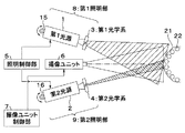
この画像取得装置は、図1に示すように、照明装置と、撮像装置と、を備えて構成されている。 As shown in FIG. 1, the image acquisition device includes an illumination device and an imaging device.
照明装置は、第1光源1および第1光学系3を備える第1照明部8と、第2光源2および第2光学系4を備える第2照明部9と、これら第1照明部8および第2照明部9を制御するための照明制御部5と、を備えている。
The illumination device includes a
また、撮像装置は、対象物を動画像や静止画像として撮像するための撮像ユニット6と、この撮像ユニット6を制御する撮像ユニット制御部7と、を備えている。
In addition, the imaging apparatus includes an
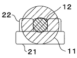
一方、照明装置により照明を行い撮像装置により撮像を行う対象物は、色の異なる複数の部位を有して構成されたものである。本実施形態においては、対象物は、図8、図10、および図1等に示すように、白色に近いが黄色からオレンジ色の傾向をもつ歯牙22および赤色から暗赤色の傾向をもつ歯肉21となっている。なお、対象物は、歯肉21および歯牙22に限られるものではない。
On the other hand, an object that is illuminated by an illuminating device and is imaged by an imaging device has a plurality of parts having different colors. In this embodiment, as shown in FIG. 8, FIG. 10, FIG. 1, etc., the target object is a
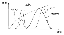
第1光源1は、例えば図2のスペクトルSP1に示すような白色光を発光するものである。
The
第2光源2は、例えば図2のスペクトルSP2に示すような光、つまり、第1光源1が発光する光とは異なる色の光であって、第1光源1のスペクトルSP1の幅に対して帯域幅の狭いピーク(強度ピーク)を(少なくとも1つ)もつ狭帯域光を例えば発光するものである。
The
ここで、第2光源2により発光される光のスペクトルは、例えば次のような原理に基づいて決定されている。
Here, the spectrum of the light emitted by the second
まず、図3を参照して、第2光源2の発光スペクトルを決定する方法について説明する。なお、この図3を含む、図3〜図6においては、縦軸および横軸に数値を記していないが、概略、図2に準ずるものとする。
First, a method for determining the emission spectrum of the second
色の異なる複数の部位を備える対象物を、それぞれの色がより好ましい色となるように照明するためには、対象物の特定部位以外の部位を適切な色となるように(例えば白色光で)照明するとともに、特定部位が特定部位以外の部位とは明確に異なる色で(つまり、色コントラストが高い状態で)照明することが望ましい。ここに、色コントラストが高いとは、具体的には、特定部位と特定部位以外の部位との色差が大きいことを意味する。従って、第2光源2の発光スペクトルは、特定部位以外の部位の色相にあまり影響を与えないようにしながら、特定部位特有の色相を明確化することを観点に決定される。
In order to illuminate an object including a plurality of parts having different colors so that each color becomes a more preferable color, a part other than a specific part of the object is appropriately colored (for example, with white light). It is desirable to illuminate and illuminate the specific part with a color clearly different from the part other than the specific part (that is, in a state where the color contrast is high). Here, the high color contrast specifically means that the color difference between the specific part and a part other than the specific part is large. Therefore, the emission spectrum of the second
ここに、特定部位以外の部位の反射スペクトル(分光反射率)をRSP1、特定部位の反射スペクトル(分光反射率)をRSP2としたときに、対象物の反射スペクトルが、例えば図3に示すようなものであったとする。この図3に示す例では、特定部位以外の部位は広い帯域の波長の光を反射する特性であるのに対して、特定部位は短波長側の狭い帯域の波長の光を反射する特性となっている。そして、これらの反射スペクトルを比較すると、特定部位の反射スペクトルRSP2は、そのピーク近傍において、特定部位以外の部位の反射スペクトルRSP1よりも高い強度値をとっている。 Here, when the reflection spectrum (spectral reflectance) of a portion other than the specific portion is RSP1, and the reflection spectrum (spectral reflectance) of the specific portion is RSP2, the reflection spectrum of the object is, for example, as shown in FIG. Suppose it was a thing. In the example shown in FIG. 3, the part other than the specific part has a characteristic of reflecting light of a wide band wavelength, whereas the specific part has a characteristic of reflecting light of a narrow band wavelength on the short wavelength side. ing. When these reflection spectra are compared, the reflection spectrum RSP2 of the specific part has a higher intensity value near the peak than the reflection spectrum RSP1 of the part other than the specific part.
従って、第2光源2により発光される光が、対象物の特定部位の分光反射率が特定部位以外の部位(ただし、第1の照明部8により照明される範囲に属する部位であって、特定部位を除外した部位)の分光反射率よりも高い強度値をとる帯域に強度ピークをもつ光となるようにすれば、特定部位と特定部位以外の部位との色差を拡大することができる。このとき、特定部位と特定部位以外の部位との色差を効率的に拡大するためには、第2光源2により発光される光の強度ピークが、対象物の特定部位の分光反射率と、上述した特定部位以外の部位の分光反射率と、の差が最大になる波長の近傍に設定されていることが好ましい。
Therefore, the light emitted from the second
このような例が、図3に示す第2光源2の発光スペクトルSP2である。なお、SP1は、第1光源1の発光スペクトルを示している。
Such an example is the emission spectrum SP2 of the second
上述したような、特定部位と特定部位以外の部位との色差の拡大は、第2光源2の発光スペクトルを、対象物の特定部位以外の部位の反射スペクトルの帯域の外に設定可能である場合にはより効率的に行うことができる。このような例を示すのが図4である。
As described above, when the color difference between the specific part and the part other than the specific part is enlarged, the emission spectrum of the second
この図4に示す例においては、特定部位の反射スペクトルRSP2と、特定部位以外の部位の反射スペクトルRSP1とは、実効的な強度値をもつ帯域が分離されている。すなわち、特定部位の反射スペクトルRSP2において実効的な強度値をもつ帯域では、特定部位以外の部位の反射スペクトルRSP1の強度値は実効的に0となっている。対象物の分光反射率特性がこの図4に示すような例である場合には、特定部位以外の部位の反射スペクトルRSP1の帯域外であって、特定部位の反射スペクトルRSP2の帯域内に第2光源2の発光スペクトルSP2を設定することにより、色差を効率的に拡大することができる。なぜならば、第2光源2から発光した光は、特定部位からは反射されるが、特定部位以外の部位からは反射されないからである。このときさらに、第2光源2により発光される光の強度ピークを、対象物の特定部位の分光反射率が最大になる波長の近傍に設定した方が良いのは上述と同様である。
In the example shown in FIG. 4, a band having an effective intensity value is separated from the reflection spectrum RSP2 of the specific part and the reflection spectrum RSP1 of the part other than the specific part. That is, in a band having an effective intensity value in the reflection spectrum RSP2 of the specific part, the intensity value of the reflection spectrum RSP1 of the part other than the specific part is effectively zero. When the spectral reflectance characteristic of the object is an example as shown in FIG. 4, it is outside the band of the reflection spectrum RSP1 of the part other than the specific part and is within the band of the reflection spectrum RSP2 of the specific part. By setting the emission spectrum SP2 of the
次に、図5は、対象物が歯肉21および歯牙22であって、特定部位が歯牙22であり、特定部位以外の部位が歯肉21である場合(すなわち、本実施形態において主に説明しているケース)の、第2光源2の発光スペクトルの設定例を示している。
Next, FIG. 5 shows a case where the object is the
特定部位である歯牙22は、上述したように、黄色からオレンジ色の傾向をもつ白色であるが、この図5に示す分光反射率スペクトルRSP2を見れば分かるように、短い波長の青色の帯域にも反射光強度をもっている。一方、特定部位以外の部位である歯肉21は、図5の分光反射率スペクトルRSP1に概略を示すように、主に長い波長である赤色の帯域に反射光強度をもっている。
As described above, the
上述したように、第2光源2により発光される光のスペクトルは、歯牙22の分光反射率の値が歯肉21の分光反射率の値よりも高くなる波長帯域に強度ピークを有するように設定すれば良いが、対象物がこの図5に示すような分光反射率を有するものである場合には、全ての可視光域において歯牙22の分光反射率の値が歯肉21の分光反射率の値よりも高いために、原理的には任意の帯域に設定可能である。しかしながら、特定部位である歯牙22と特定部位以外の部位である歯肉21との色差を効率的に拡大するためは、上述したように、歯肉21の分光反射率の波長帯域外になるように第2光源2の発光スペクトルを設定することが好ましい。このような好ましい設定例を示すのが図5である。すなわち、第2光源2により発光される光を、この図5のスペクトルSP2、あるいは数値的により詳しくは図2のスペクトルSP2に示すような、青色の狭帯域光に設定すれば良いことになる。
As described above, the spectrum of the light emitted from the second
なお、上述したように、対象物は、歯肉21および歯牙22に限られるものではない(すなわち、本実施形態の技術の適用範囲は、歯牙観察に限るものではない)。図6は対象物の特定部位の反射スペクトルの帯域が特定部位以外の部位の反射スペクトルの帯域よりも長波長側であるときの第2光源2の反射スペクトルの設定例を示している。
As described above, the object is not limited to the
この図6に示す例においては、特定部位以外の部位の反射スペクトルRSP1の帯域が例えば緑色から青色にかけての帯域であるとすると、特定部位の反射スペクトルRSP2の帯域はより長波長側の例えば赤色の帯域となっている。この図6に示す例においては、さらに、特定部位の反射スペクトルRSP2の実効的な強度値をもつ帯域と、特定部位以外の部位の反射スペクトルRSP1の実効的な強度値をもつ帯域とが分離されている。 In the example shown in FIG. 6, if the band of the reflection spectrum RSP1 of the part other than the specific part is a band from, for example, green to blue, the band of the reflection spectrum RSP2 of the specific part is, for example, red on the longer wavelength side. It is a band. In the example shown in FIG. 6, a band having an effective intensity value of the reflection spectrum RSP2 of the specific part and a band having an effective intensity value of the reflection spectrum RSP1 of the part other than the specific part are further separated. ing.
対象物がこの図6に示すようなものである場合には、第2光源2により発光される光を、特定部位以外の部位の反射スペクトルRSP1の帯域外の帯域を有するように(すなわち、第2光源2により発光される光が全て反射スペクトルRSP1の帯域外にある必要はない(ただし、第2光源2により発光される光が全て反射スペクトルRSP1の帯域外となる方が好ましい))、かつ、特定部位の反射スペクトルRSP2の強度値が最大となる波長位置に強度ピークを有するように設定すると良い。
When the object is as shown in FIG. 6, the light emitted from the second
再び図1を参照しながら、構成の説明を続ける。 The description of the configuration is continued with reference to FIG. 1 again.
第1光学系3は、第1光源1により発光された白色光を図7の曲線OR1に示すような第1の指向特性をもって照射するためのものである。
The first
第2光学系4は、第2光源2により発光された狭帯域光を、対象物の位置において、上述した第1の指向特性による第1の照射範囲に含まれる第2の照射範囲となるような第2の指向特性をもって照射するためのものである。具体的には、第2の指向特性は、図7の曲線OR2に示すように、第1の指向特性によるスポット径よりも小さいスポット径となるように光を照射する指向特性となっている。ここに、スポット径は、所定値以上の明るさ強度が得られる範囲として捉えることができる。
The second
照明制御部5は、第1光源1と第2光源2とに電力を供給して、これらを制御しながら発光を行わせるものである。
The
撮像ユニット6は、上述したような照明装置により照明された対象物を撮像して、画像信号を取得するためのものである。すなわち、撮像ユニット6は、撮像光学系や撮像素子を備えて構成され、撮像光学系により対象物の光学像を撮像素子上に結像して、撮像素子により光学像の光電変換を行い、画像信号として出力する。
The
撮像ユニット制御部7は、撮像ユニット6を制御して撮像を行わせ、画像信号を取得するものである。
The imaging
次に、照明装置による対象物の照明について、図8から図10を参照して説明する。 Next, illumination of the object by the illumination device will be described with reference to FIGS.
対象物である歯牙22および歯肉21は、撮像ユニット6側から見ると、図8に示すような形状をなしている。
The
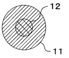
このような対象物に対して、第1照明部8と第2照明部9とを用いて、図9に示すような、第1の照射範囲11の白色照明スポットと、第2の照射範囲12の狭帯域照明スポットと、による照明を行う。ここに、第1照明部8および第2照明部9は、対象物の位置において、第2の照射範囲12が第1の照射範囲11に含まれるように照明を行っている。
For such an object, the
そして、このような照明スポットにより照明されている対象物の様子を示すのが図10である。 FIG. 10 shows the state of the object illuminated by such an illumination spot.
今、着目している歯牙22に対しては、白色光と狭帯域光との両方が照射され、つまり混色領域(加法混色領域)となっている。一方、着目している歯牙22以外の歯牙22および歯肉21は、白色光による照明が行われている。このとき、加法混色領域では、それ以外の領域に比べて、青色の帯域を有する光が多く照射されることになる。この青色の帯域における分光反射率は、歯肉21に比べて歯牙22において高くなっているので、青色の反射光は、歯肉21に比べて歯牙22から多く反射する。すなわち、分光反射率が歯肉21よりも歯牙22において高い帯域を有する光は、狭帯域光が照射された第2の照射範囲のうち、着目している歯牙22から多く反射する。これにより、着目している歯牙22と歯肉21との色差が向上するので、両者の色コントラストは高くなる。
At present, the
なお、上述では照射範囲11,12がほぼ円形となるようにしているが、もちろんこれに限るものではなく、その他の形状となるようにしても良い。例えば、白色光の照射範囲11は円形をなすが、狭帯域光の照射範囲12は横長の矩形状(あるいは横長の楕円状)をなすようにして、着目する歯牙22以外の歯牙22についても白色光と狭帯域光との両方が照射されるようにしても良い。
In the above description, the irradiation ranges 11 and 12 are substantially circular. However, the present invention is not limited to this, and may be other shapes. For example, the white
また、上述では、第2照明部9により照射される光が狭帯域光であるとして説明したが、これに限るものではなく、例えば対象物の特定部位の色を強調するような(つまり、対象物の特定部位とほぼ同じ色相をもっていて、特定部位の彩度を上げるような)色を有する広帯域光等であっても構わない。 In the above description, the light emitted from the second illumination unit 9 is described as narrowband light. However, the present invention is not limited to this. For example, the color of a specific part of the target is emphasized (that is, the target It may be broadband light having a color that has substantially the same hue as the specific part of the object and increases the saturation of the specific part.
さらに、上述では、第2照明部9を1つだけ設けているが、対象物を構成する各部位の色数等に応じて、白色光と異なる色の光を照射する照明部を複数設けても良いことはもちろんである。 Furthermore, although only one second illumination unit 9 is provided in the above description, a plurality of illumination units that irradiate light of a color different from white light are provided according to the number of colors of each part constituting the object. Of course it is also good.
このような実施形態1によれば、対象物の特定部位と他の部位との色コントラストを向上させるように照明することができる。この結果、色の異なる複数の部位を備える対象物を、それぞれの色がより好ましい色となるように照明することができる。
According to
[実施形態2]
図11から図14は本発明の実施形態2を示したものであり、図11は照明装置と撮像装置とを備える画像取得装置の構成を示す図、図12は第1の照射範囲の中央に第2の照射範囲が位置する様子を示す図、図13は第1の照射範囲の右上に第2の照射範囲が位置する様子を示す図、図14は第1の照射範囲の左下に第2の照射範囲が位置する様子を示す図である。
[Embodiment 2]
FIG. 11 to FIG. 14
この実施形態2において、上述の実施形態1と同様である部分については同一の符号を付して説明を省略し、主として異なる点についてのみ説明する。 In the second embodiment, parts that are the same as those in the first embodiment are given the same reference numerals and description thereof is omitted, and only differences are mainly described.
この実施形態2は、第1照明部8および第2照明部9を可動式として、第1の指向特性による照射方向と、第2の指向特性による照射方向と、を相対的に変更することができるようにしたものとなっている。
In the second embodiment, the
すなわち、第1の照明部8には第1の指向特性による照射方向を変更するための照明可動部15が、第2の照明部9には第2の指向特性による照射方向を変更するための照明可動部16が、それぞれ設けられている。ここに、照明可動部15,16は、ボールジョイントやヒンジ等で構成された手動式のものであっても良いし、駆動源の駆動力に基づき照射方向を変更するような電動式のものであっても構わない。
That is, the
そして、このような照明可動部15,16を用いることにより、図12〜図14に示すように、第1の照射範囲11中の混色領域となる第2の照射範囲12の位置を、任意に変えることができるようになっている。
And by using such illumination
なお、上述では、第1の照明部8と第2の照明部9との両方に照明可動部を設けて、それぞれが独立に照射方向を変更することができるようにしたが、これに限るものではなく、例えば何れか一方にのみ照明可動部を設けるようにすることも可能である。この場合であっても、照射方向を相対的に変更することが可能であり、絶対的な照射方向の変更は照明装置全体(あるいは画像取得装置全体)の方向を変更すれば足りるためである。
In the above description, the illumination movable unit is provided in both the
このような実施形態2によれば、上述した実施形態1とほぼ同様の効果を奏するとともに、第1の照射範囲内における第2の照射範囲の位置を任意に変更することができるために、対象物を構成する複数色の分布に応じた最適な照明を行うことが可能となる。 According to the second embodiment, the same effect as that of the first embodiment described above can be obtained, and the position of the second irradiation range in the first irradiation range can be arbitrarily changed. It is possible to perform optimal illumination according to the distribution of a plurality of colors constituting the object.
[実施形態3]
図15から図18は本発明の実施形態3を示したものであり、図15は照明装置と撮像装置とを備える画像取得装置の構成を示す図、図16は対象物が照明装置から近距離にあるときの第1照明部および第2照明部の指向特性の様子を模式的に示す図、図17は対象物が照明装置から中距離にあるときの第1照明部および第2照明部の指向特性の様子を模式的に示す図、図18は対象物が照明装置から遠距離にあるときの第1照明部および第2照明部の指向特性の様子を模式的に示す図である。
[Embodiment 3]
FIGS. 15 to 18
この実施形態3において、上述の実施形態1,2と同様である部分については同一の符号を付して説明を省略し、主として異なる点についてのみ説明する。 In the third embodiment, parts that are the same as those in the first and second embodiments are given the same reference numerals, description thereof is omitted, and only differences are mainly described.
この実施形態3は、第1照明部8,第2照明部9に第1,第2指向特性変更部32,33をそれぞれ設けて、照明装置から対象物までの距離が異なっても、ほぼ同一の照明を行うことができるようにしたものである。
In the third embodiment, the
すなわち、第1光源1から照射される白色光の光路上には第1指向特性変更部32が、第2光源2から照射される狭帯域光の光路上には第2指向特性変更部33が、それぞれ設けられている。ここに、図15に示す例においては、これらの第1指向特性変更部32および第2指向特性変更部33が例えばズーム光学系として構成されたものとなっている。
That is, the first
また、本実施形態の照明装置は、測距部31を備えており、第1照明部8および第2照明部9から対象物までの距離を測定することができるようになっている。
Moreover, the illuminating device of this embodiment is provided with the ranging
この測距部31により測定して得られた距離情報は、第1,第2指向特性変更部32,33へ伝達される。
The distance information obtained by the measurement by the
第1,第2指向特性変更部32,33は、伝達された距離情報に基づいて、図16〜図18に示すように、対象物までの距離に関わらず、ほぼ同一の照射範囲の照明を行うことができるように指向特性を変更する。
Based on the transmitted distance information, the first and second directivity
すなわち、第1,第2指向特性変更部32,33は、対象物が照明装置から近距離にあるときには、図16に第1の照射角度範囲11aおよび第2の照射角度範囲12aとして示すように、比較的広い角度範囲の指向特性に変更する。
That is, when the target is at a short distance from the illumination device, the first and second
また、第1,第2指向特性変更部32,33は、対象物が照明装置から中距離にあるときには、図17に第1の照射角度範囲11aおよび第2の照射角度範囲12aとして示すように、中程度の角度範囲の指向特性に変更する。
Further, the first and second directivity
さらに、第1,第2指向特性変更部32,33は、対象物が照明装置から遠距離にあるときには、図18に第1の照射角度範囲11aおよび第2の照射角度範囲12aとして示すように、比較的狭い角度範囲の指向特性に変更する。
Furthermore, the first and second directivity
これら図16〜図18の何れに場合にも、第1,第2指向特性変更部32,33は、上述した第1の照射角度範囲11aおよび第2の照射角度範囲12aによる対象物の位置における第1の照射範囲11と第2の照射範囲12とが略同一となるように、指向特性の制御を行っている。具体的には、第1の被写体距離をd1、第1の被写体距離における照射角度の半分をθ1とし、第2の被写体距離をd2、第1の被写体距離における照射角度の半分をθ2とすると、第1照明部8および第2照明部9の何れについても、
d1・tanθ1=d2・tanθ2
が満たされるように指向特性を変更するようになっている。
In any of these FIGS. 16 to 18, the first and second directivity
d1 · tan θ1 = d2 · tan θ2
The directional characteristics are changed so that is satisfied.
なお、上述では、第1指向特性変更部32と第2指向特性変更部33とをそれぞれ別個に設けたが、照明光学系を工夫して例えばハーフミラーを用いる等により、第1光学系3による照明光軸と第2光学系4による照明光軸とが一致するような照明を行うことができる場合には、1つの指向特性変更部を設けるようにするだけでも構わない。
In the above description, the first directivity
このような実施形態3によれば、上述した実施形態1とほぼ同様の効果を奏するとともに、対象物までの距離が異なっても、ほぼ同一の照明を行うことが可能となる。そして、指向特性の変更が、測距部31により得られた距離情報に基づいて自動的に行われるために、面倒な手動操作等を要することなく、適切な照明を行うことができる。
According to the third embodiment as described above, substantially the same effect as that of the first embodiment described above can be obtained, and substantially the same illumination can be performed even if the distance to the object is different. Since the directivity change is automatically performed based on the distance information obtained by the
[実施形態4]
図19から図22は本発明の実施形態4を示したものであり、図19は照明装置と撮像装置とを備える画像取得装置の構成を示す図、図20は第1光源による発光強度を強くするとともに第2光源による発光強度を弱くしたときの混色領域の様子を示す図、図21は第1光源による発光強度を中程度にするとともに第2光源による発光強度を中程度にしたときの混色領域の様子を示す図、図22は第1光源による発光強度を弱くするとともに第2光源による発光強度を強くしたときの混色領域の様子を示す図である。
[Embodiment 4]
FIGS. 19 to 22
この実施形態4において、上述の実施形態1〜3と同様である部分については同一の符号を付して説明を省略し、主として異なる点についてのみ説明する。 In the fourth embodiment, the same parts as those in the first to third embodiments are denoted by the same reference numerals, description thereof is omitted, and only different points will be mainly described.
この実施形態4は、第1光源1による発光強度と第2光源2による発光強度とをそれぞれ独立に制御して、混色領域における混色比を所望に設定することができるようにしたものである。
In the fourth embodiment, the light emission intensity by the first
すなわち、照明制御部5は、第1光源1の発光強度を制御することにより対象物へ照射する光の強度を制御するための照射光強度制御部たる第1出力制御部35と、第2光源2の発光強度を制御することにより対象物へ照射する光の強度を制御するための照射光強度制御部たる第2出力制御部36と、を備えて構成されている。
That is, the
第1出力制御部35と第2出力制御部36は、例えば図示しない操作部からの入力に基づいて、第1光源1へ供給する電力を制御すると共に、第2光源2へ供給する電力を制御することにより、これら第1光源1の発光強度と第2光源2の発光強度とをそれぞれ独立に制御するようになっている。
The first output control unit 35 and the second
すなわち、例えば図20に示すように、第1出力制御部35が第1光源1による発光強度を強くするように制御する一方で、第2出力制御部36が第2光源2による発光強度を弱くするように制御する。なお、図20〜図22においては、ハッチングの間隔が狭いことが発光強度が強いことを示し、逆に、ハッチングの間隔が広いことが発光強度が弱いことを示している。
That is, for example, as shown in FIG. 20, the first output control unit 35 controls to increase the emission intensity by the first
また、例えば図21に示すように、第1出力制御部35が第1光源1による発光強度を中程度にするように制御する一方で、第2出力制御部36が第2光源2による発光強度を中程度にするように制御する。
For example, as shown in FIG. 21, the first output control unit 35 controls the light emission intensity of the first
さらに、例えば図22に示すように、第1出力制御部35が第1光源1による発光強度を弱くするように制御する一方で、第2出力制御部36が第2光源2による発光強度を強くするように制御する。
Furthermore, for example, as shown in FIG. 22, the first output control unit 35 controls the light emission intensity of the first
なお、上述では、第1光源1の発光強度と第2光源2の発光強度とをそれぞれ独立に制御しているが、これに限らず、一方の発光強度のみを制御する構成であっても混色比を変えることが可能である。
In the above description, the light emission intensity of the first
また、上述では、第1光源1および第2光源2の発光強度を制御することにより、第1照明部8および第2照明部9から対象物へ向けて照射する光の強度を制御しているが、これに限るものではなく、例えば濃度を可変することができる透過型のフィルタを設けて、この透過型フィルタの濃度を制御することにより、照射する光の強度を制御するようにしても構わない。ただし、構成が簡単で消費電力を少なくすることができるという観点からは、光源の発光強度を制御する方法の方が優れているといえる。
In the above description, the intensity of light emitted from the
このような実施形態4によれば、上述した実施形態1とほぼ同様の効果を奏するとともに、混色領域の混色比を任意に変更することが可能となるために、対象物の特定部位である例えば歯牙22が、黄色に近い色であるか、オレンジ色に近い色であるか、等に応じて、より適切な色となるように照明することが可能になる。
According to the fourth embodiment, the same effect as that of the first embodiment described above can be obtained, and the color mixture ratio of the color mixture region can be arbitrarily changed. It is possible to illuminate the
[実施形態5]
図23、図24は本発明の実施形態5を示したものであり、図23は照明装置と撮像装置とを備える画像取得装置の構成を示す図、図24は撮像ユニットの構成をより詳しく示すブロック図である。
[Embodiment 5]
FIGS. 23 and 24
この実施形態5において、上述の実施形態1〜4と同様である部分については同一の符号を付して説明を省略し、主として異なる点についてのみ説明する。 In the fifth embodiment, the same parts as those in the first to fourth embodiments are denoted by the same reference numerals, description thereof is omitted, and only different points will be mainly described.
この実施形態5は、照明の制御を操作に応じて行い、撮像ユニット6に自動合焦機能を備えさせると共に、撮像して得られた画像を表示するようにしたものである。
In the fifth embodiment, the illumination is controlled according to the operation, the
すなわち、図23に示すように、照明制御部5には操作部41からの操作信号が入力されるようになっている。ここに、操作部41により操作可能な制御としては、例えば上述した実施形態4において説明したような各光源1,2の光量制御や、上述した実施形態3において説明したような指向特性の変更、あるいは上述した実施形態2において説明したような照射方向の制御などが挙げられる(ただし、図23における図示は省略している)。
That is, as shown in FIG. 23, an operation signal from the operation unit 41 is input to the
撮像ユニット6は、図24に示すように、撮像素子を含む撮像部としての撮像デバイス44と、この撮像デバイス44に対象物の光学像を結像する撮像光学系を焦点調節して自動合焦を行うための自動合焦部45と、を備えて構成されていて、撮像デバイス44により得られた画像信号(動画像信号または静止画像信号の何れでも構わないが、ここでは例えば動画像信号であるものとする)を、撮像ユニット制御部7へ出力するようになっている。
As shown in FIG. 24, the
また、撮像ユニット制御部7は、信号処理部42に接続されていて、撮像ユニット6から得られた画像信号をこの信号処理部42へ出力するようになっている。
The imaging
信号処理部42は、撮像ユニット制御部7から入力された画像信号を信号処理して表示可能な映像信号を生成し、表示部43へ出力するものである。
The
表示部43は、信号処理部42からの映像信号により画像を表示するものである。なお、表示部43を複数設けて、これら複数の表示部43により画像をそれぞれ表示するようにしても良い。
The display unit 43 displays an image using the video signal from the
このような実施形態5によれば、上述した実施形態1とほぼ同様の効果を奏するとともに、撮像ユニット6に自動合焦部45を設けたために、焦点調節を自動的に行うことが可能となり、手動等による調節の手間を省くことが可能となる。
According to the fifth embodiment as described above, substantially the same effects as those of the first embodiment described above can be obtained, and the automatic focusing
また、撮像して得られた画像信号を信号処理部42により信号処理して映像信号を生成し、表示部43に表示するようにしたために、照明している対象物の画像を例えばリアルタイムに観察することが可能となる。
In addition, since the image signal obtained by imaging is processed by the
加えて、表示部43に表示しているために、画像取得装置を操作している者のみでなく、その他の者も画像を観察することが可能となる。例えば歯科の分野においては、従来は、歯の治療を行っている歯科医師等のみが治療の経過を観察することができるが、例えば研修医等は治療前の様子と治療後の様子とを観察することができるに過ぎず、十分な教育効果を上げることが困難であった。これに対して、本実施形態の構成によれば、研修医等も治療の様子をリアルタイムに観察することが可能となって、より大きな教育効果を上げることができる。 In addition, since the image is displayed on the display unit 43, not only the person who operates the image acquisition apparatus but also other persons can observe the image. For example, in the field of dentistry, conventionally, only the dentist who is treating teeth can observe the progress of treatment, but for example, the trainees observe the state before treatment and the state after treatment However, it was difficult to achieve a sufficient educational effect. On the other hand, according to the configuration of the present embodiment, it becomes possible for a resident doctor or the like to observe the state of treatment in real time, and a greater educational effect can be achieved.
さらに、本実施形態においては操作部41を設けたために、照明制御部5を介した第1照明部8および第2照明部9の制御を、手動でも行うことが可能となる。
Furthermore, since the operation unit 41 is provided in the present embodiment, the control of the
[実施形態6]
図25は本発明の実施形態6を示したものであり、図25は照明装置と撮像装置とを備える画像取得装置の構成を示すブロック図である。この実施形態6において、上述の実施形態1〜5と同様である部分については同一の符号を付して説明を省略し、主として異なる点についてのみ説明する。
[Embodiment 6]
FIG. 25 shows
この実施形態6は、撮像ユニット6に可変倍率部51を設けて、この撮像ユニット6の制御を操作に応じて行うことができるようにしたものとなっている。
In the sixth embodiment, a
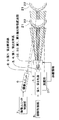
まず、照明装置を構成する照明ユニットは、図25に示すように、第1照明部8と第2照明部9とを備えている。
First, the illumination unit which comprises an illuminating device is provided with the
第1照明部8は、第1光源1と、第1光学系3と、第1指向特性変更部32と、を備えている。
The
第2照明部9は、第2光源2と、第1光学系4と、を備えている。
The second illumination unit 9 includes the second
撮像ユニット6は、撮像デバイス44と、可変倍率部51と、を備えている。ここに、可変倍率部51は、撮像デバイス44に結像される光学像を変倍するもの(例えば、この撮像ユニット6の撮像光学系に含まれる変倍光学系を制御して光学像を変倍するもの)であっても構わないし、あるいは撮像デバイス44により得られる画像信号から特定部分を切り出して拡大する電子ズームタイプのものであっても構わない。そして、撮像ユニット6は、倍率情報を照明ユニットと照明制御部5とへ出力するようになっている。
The
撮像ユニット制御部7は、制御信号を撮像ユニット6へ送信し、撮像ユニット6から画像信号を受信するようになっている。この撮像ユニット制御部7は、操作部52から操作信号が入力されるようになっていて、この操作部52により可能な操作入力として、可変倍率部51による倍率が含まれている。
The
撮像ユニット制御部7は、撮像ユニット6から受信した画像信号を、信号処理部42へ出力する。
The
信号処理部42は、入力された画像信号を映像信号に変換して、表示部43へ出力する。
The
表示部43は、信号処理部42から入力される映像信号により画像を表示する。
The display unit 43 displays an image using the video signal input from the
次に、このような構成において、変倍を行って撮像を行うときの作用について説明する。 Next, an operation when imaging is performed by zooming in such a configuration will be described.
例えば、撮像しようとしている対象物を一定の大きさで撮像したい場合などに、操作部52から変倍情報を入力する。このときに、撮像ユニット6による撮像を行って、表示部43に表示をしながら変倍情報を入力すれば、映像を確認しながら所望の変倍情報を入力することができる。
For example, zooming information is input from the
すると、撮像ユニット制御部7は、この変倍情報に基づいて撮像ユニット6へ制御信号を送信する。撮像ユニット6の可変倍率部51は、この制御信号を受信すると、撮像デバイス44上に結像される対象物の光学像を変倍する(あるいは電子ズームの場合には、撮像デバイス44から得られる画像の一部を切り出して画像信号として出力する)。
Then, the imaging
そして、この可変倍率部51により光学像がどれだけ変倍されたかを示す倍率情報が、照明制御部5と第1指向特性変更部32とへ送信される。
Then, magnification information indicating how much the optical image has been scaled by the
第1指向特性変更部32は、入力された倍率情報に基づいて、変更された撮像範囲に対応するように、第1照明部8により照明光を照射する第1の指向特性を変更する。具体的には、例えば最初に可変倍率部51によりワイド端で撮像が行われているとすると、第1照明部8による第1の照射範囲11はこのワイド端での撮像範囲を含む広い範囲となる。その後に、ズームアップされてより狭い画角の撮像が行われるとすると、ワイド端での第1の照射範囲11はこのズームアップされた撮像範囲よりも広くなり過ぎて照明光が無駄になる。そこで、第1指向特性変更部32は、入力された倍率情報に基づいて、そのときの撮像範囲をぎりぎり含む程度に照射範囲11を狭くするように第1照明部8の指向特性を変更する。つまり、第1指向特性変更部32は、可変倍率部51からの倍率情報に基づいて、第1の照明部8による第1の照射範囲11が、撮像範囲を含み、かつこの撮像範囲よりも所定値(予め定められた許容範囲を示す値)以上広くなることがないように、第1の指向特性を変更するようになっている。
Based on the input magnification information, the first
また、照明制御部5は、第1指向特性変更部32により指向特性が変更されても、対象物が同一の明るさで撮像されるように、入力された倍率情報に基づいて、第1光源1へ出力する電力を制御する(このときには、第2光源2へ出力する電力は一定で構わない。なぜならば、撮像ユニット6を変倍したときには、対象物の特定部位は変倍して撮像されるが、実際の特定部位の大きさは一定であって、第2照明部9による指向特性は変更する必要がないためである。)。
Further, the
このような制御を行うことにより、撮像ユニット6の変倍に合わせた必要最小限の照明を行うことが可能となる。
By performing such control, it is possible to perform the minimum necessary illumination according to the magnification of the
なお、上述では、対象物を一定の大きさで撮像したい場合を一例としてあげたが、もちろん、所望の大きさで撮像したい場合であっても上述した技術を同様に適用することができる。 In the above description, the case where an object is desired to be imaged at a certain size has been described as an example. However, the above-described technique can be similarly applied even when an object is desired to be imaged at a desired size.
また、その他の作用は、上述した各実施形態とほぼ同様である。 Other operations are almost the same as those in the above-described embodiments.
このような実施形態6によれば、上述した各実施形態とほぼ同様の効果を奏するとともに、撮像ユニット6に対する変倍操作を行うだけで、変倍情報に応じた適切な指向特性(必要最小限の照射範囲)の照明を、照明装置により自動的に行うことが可能となる。これにより、面倒な操作を要することなく、無駄な電力の消費を低減することが可能となる。特に、表示部43を介して動画像を観察する場合には、静止画像の場合と異なり照明光を継続して照射する必要があるために、消費電力低減の効果を大きく得ることができる。
According to the sixth embodiment, the effects similar to those of the above-described embodiments can be obtained, and appropriate directivity characteristics (minimum necessary) corresponding to the magnification information can be obtained by simply performing the magnification operation on the
そして、撮像ユニット6により撮像を行い表示部43により表示を行いながら変倍操作を実行することができるために、映像を実際に確認しながら操作性良く変倍操作を行うことが可能となる。
Since the magnification change operation can be performed while the image is picked up by the
なお、本発明は上述した実施形態そのままに限定されるものではなく、実施段階ではその要旨を逸脱しない範囲で構成要素を変形して具体化することができる。また、上記実施形態に開示されている複数の構成要素の適宜な組み合わせにより、種々の発明を形成することができる。例えば、実施形態に示される全構成要素から幾つかの構成要素を削除しても良い。さらに、異なる実施形態にわたる構成要素を適宜組み合わせても良い。このように、発明の主旨を逸脱しない範囲内において種々の変形や応用が可能であることは勿論である。 Note that the present invention is not limited to the above-described embodiments as they are, and can be embodied by modifying the constituent elements without departing from the scope of the invention in the implementation stage. Moreover, various inventions can be formed by appropriately combining a plurality of constituent elements disclosed in the embodiment. For example, you may delete a some component from all the components shown by embodiment. Furthermore, the constituent elements over different embodiments may be appropriately combined. Thus, it goes without saying that various modifications and applications are possible without departing from the spirit of the invention.
1…第1光源
2…第2光源
3…第1光学系
4…第2光学系
5…照明制御部
6…撮像ユニット(撮像装置)
7…撮像ユニット制御部(撮像装置)
8…第1照明部
9…第2照明部
11…第1の照射範囲
11a…第1の照射角度範囲
12…第2の照射範囲
12a…第2の照射角度範囲
15,16…照明可動部
21…歯肉(対象物)
22…歯牙(対象物の特定部位)
31…測距部
32…第1指向特性変更部
33…第2指向特性変更部
35…第1出力制御部(照射光強度制御部)
36…第2出力制御部(照射光強度制御部)
41…操作部
42…信号処理部
43…表示部
44…撮像デバイス(撮像部)
45…自動合焦部
51…可変倍率部
52…操作部
DESCRIPTION OF
7 ... Imaging unit controller (imaging device)
DESCRIPTION OF
22 ... Tooth (specific part of the object)
DESCRIPTION OF
36 ... 2nd output control part (irradiation light intensity control part)
DESCRIPTION OF SYMBOLS 41 ...
45 ... automatic focusing
Claims (13)
上記第1の光源とは異なる色の光を発光する第2の光源と、上記第2の光源により発光された光を、上記第1の指向特性による第1の照射範囲に含まれかつ該第1の照射範囲よりも小さい第2の照射範囲となるような第2の指向特性をもって照射するための第2の光学系と、を有する第2の照明部と、
を具備したことを特徴とする照明装置。 A first illumination unit comprising: a first light source that emits white light; and a first optical system that irradiates the white light emitted from the first light source with a first directivity characteristic;
The second light source that emits light of a color different from that of the first light source and the light emitted by the second light source are included in the first irradiation range by the first directivity and are A second illuminating unit having a second optical system for irradiating with a second directional characteristic such that the second irradiation range is smaller than the first irradiation range;
An illumination device comprising:
上記測距部により測定された距離情報に基づいて、上記第1の照明部および上記第2の照明部から上記対象物までの距離に依ることなく上記第1の照射範囲および上記第2の照射範囲が一定となるように、上記第1の指向特性および上記第2の指向特性を変更する指向特性変更部と、
をさらに具備したことを特徴とする請求項1に記載の照明装置。 A distance measuring unit for measuring a distance from the first illumination unit and the second illumination unit to an object to be illuminated; and
Based on the distance information measured by the distance measuring unit, the first irradiation range and the second irradiation without depending on the distance from the first illumination unit and the second illumination unit to the object. A directivity changing unit that changes the first directivity and the second directivity so that the range is constant;
The illumination device according to claim 1, further comprising:
上記照明装置により照明された対象物を撮像して画像信号を取得するための撮像装置と、
を具備したことを特徴とする画像取得装置。 A lighting device according to claim 1;
An imaging device for capturing an image of an object illuminated by the illumination device and obtaining an image signal;
An image acquisition apparatus comprising:
上記第1の照明部および上記第2の照明部から、照明を行う対象となる対象物までの距離を測定するための測距部と、
上記測距部により測定された距離情報に基づいて、上記第1の照明部および上記第2の照明部から上記対象物までの距離に依ることなく上記第1の照射範囲および上記第2の照射範囲が一定となるように、上記第1の指向特性および上記第2の指向特性を変更する指向特性変更部と、
をさらに有するものであることを特徴とする請求項6に記載の画像取得装置。 The lighting device is
A distance measuring unit for measuring a distance from the first illumination unit and the second illumination unit to an object to be illuminated; and
Based on the distance information measured by the distance measuring unit, the first irradiation range and the second irradiation without depending on the distance from the first illumination unit and the second illumination unit to the object. A directivity changing unit that changes the first directivity and the second directivity so that the range is constant;
The image acquisition apparatus according to claim 6, further comprising:
上記信号処理により生成された映像信号を表示する表示部と、
をさらに具備したことを特徴とする請求項6に記載の画像取得装置。 A signal processing unit that generates a video signal that can be displayed by performing signal processing on the image signal acquired by the imaging device;
A display unit for displaying a video signal generated by the signal processing;
The image acquisition apparatus according to claim 6, further comprising:
上記照明部は、上記可変倍率部からの倍率情報に基づいて、上記第1の照明部による上記第1の照射範囲が、上記撮像範囲を含み、かつ該撮像範囲よりも所定値以上広くなることがないように、上記第1の指向特性を変更する指向特性変更部をさらに有するものであることを特徴とする請求項6に記載の画像取得装置。 The imaging apparatus includes a variable magnification unit that changes an imaging range of an image and outputs magnification information according to the changed imaging range.
In the illumination unit, based on the magnification information from the variable magnification unit, the first irradiation range by the first illumination unit includes the imaging range and is wider than the imaging range by a predetermined value or more. The image acquisition apparatus according to claim 6, further comprising a directivity characteristic changing unit configured to change the first directivity characteristic so that the first directivity characteristic does not exist.
Priority Applications (5)
| Application Number | Priority Date | Filing Date | Title |
|---|---|---|---|
| JP2008109283A JP2009259703A (en) | 2008-04-18 | 2008-04-18 | Lighting device, and image acquisition apparatus |
| PCT/JP2009/057306 WO2009128391A1 (en) | 2008-04-18 | 2009-04-03 | Illumination device and image acquisition apparatus |
| KR1020107020876A KR20110007107A (en) | 2008-04-18 | 2009-04-03 | Illumination device and image acquisition apparatus |
| CN2009801015711A CN101909515A (en) | 2008-04-18 | 2009-04-03 | Illumination device and image acquisition apparatus |
| US12/905,144 US20110032350A1 (en) | 2008-04-18 | 2010-10-15 | Illumination device and image acquisition apparatus |
Applications Claiming Priority (1)
| Application Number | Priority Date | Filing Date | Title |
|---|---|---|---|
| JP2008109283A JP2009259703A (en) | 2008-04-18 | 2008-04-18 | Lighting device, and image acquisition apparatus |
Publications (1)
| Publication Number | Publication Date |
|---|---|
| JP2009259703A true JP2009259703A (en) | 2009-11-05 |
Family
ID=40739922
Family Applications (1)
| Application Number | Title | Priority Date | Filing Date |
|---|---|---|---|
| JP2008109283A Pending JP2009259703A (en) | 2008-04-18 | 2008-04-18 | Lighting device, and image acquisition apparatus |
Country Status (5)
| Country | Link |
|---|---|
| US (1) | US20110032350A1 (en) |
| JP (1) | JP2009259703A (en) |
| KR (1) | KR20110007107A (en) |
| CN (1) | CN101909515A (en) |
| WO (1) | WO2009128391A1 (en) |
Cited By (15)
| Publication number | Priority date | Publication date | Assignee | Title |
|---|---|---|---|---|
| JP2011150039A (en) * | 2010-01-20 | 2011-08-04 | Stanley Electric Co Ltd | Stroboscopic device |
| JP2011206226A (en) * | 2010-03-29 | 2011-10-20 | Fujifilm Corp | Endoscopic system |
| JP2015027470A (en) * | 2014-08-25 | 2015-02-12 | 富士フイルム株式会社 | Endoscope apparatus |
| JP2015521871A (en) * | 2012-07-06 | 2015-08-03 | ソシエテ プール ラ コンセプシオン デ アプリカシオン デ テクニクエレクトロニク−サテレク | Intraoperative lighting system |
| JP2016514972A (en) * | 2013-01-29 | 2016-05-26 | コーニンクレッカ フィリップス エヌ ヴェKoninklijke Philips N.V. | Light source, luminaire and surgical lighting unit |
| JP2016105838A (en) * | 2016-03-01 | 2016-06-16 | 富士フイルム株式会社 | Endoscope apparatus |
| JP2017033629A (en) * | 2015-07-28 | 2017-02-09 | パナソニックIpマネジメント株式会社 | Lighting apparatus |
| JP2017087078A (en) * | 2017-02-28 | 2017-05-25 | 富士フイルム株式会社 | Endoscope apparatus |
| JP2019506698A (en) * | 2015-11-13 | 2019-03-07 | ノバダック テクノロジーズ ユーエルシー | System and method for target illumination and imaging |
| US10694152B2 (en) | 2006-12-22 | 2020-06-23 | Novadaq Technologies ULC | Imaging systems and methods for displaying fluorescence and visible images |
| CN112422932A (en) * | 2020-09-22 | 2021-02-26 | 环鸿科技股份有限公司 | Preprocessing method and system for improving image recognition rate |
| USD916294S1 (en) | 2016-04-28 | 2021-04-13 | Stryker European Operations Limited | Illumination and imaging device |
| US10980420B2 (en) | 2016-01-26 | 2021-04-20 | Stryker European Operations Limited | Configurable platform |
| US10992848B2 (en) | 2017-02-10 | 2021-04-27 | Novadaq Technologies ULC | Open-field handheld fluorescence imaging systems and methods |
| US11756674B2 (en) | 2016-06-14 | 2023-09-12 | Stryker European Operations Limited | Methods and systems for adaptive imaging for low light signal enhancement in medical visualization |
Families Citing this family (22)
| Publication number | Priority date | Publication date | Assignee | Title |
|---|---|---|---|---|
| MX2010010292A (en) | 2008-03-18 | 2011-01-25 | Novadaq Technologies Inc | Imaging system for combined full-color reflectance and near-infrared imaging. |
| US20110285895A1 (en) * | 2010-05-21 | 2011-11-24 | Chung Shan Institute Of Science And Technology | Image Sensing Device and Processing System |
| US9277855B2 (en) * | 2010-08-10 | 2016-03-08 | Boston Scientific Scimed, Inc. | Endoscopic system for enhanced visualization |
| JP5371920B2 (en) * | 2010-09-29 | 2013-12-18 | 富士フイルム株式会社 | Endoscope device |
| JP5864870B2 (en) * | 2011-03-01 | 2016-02-17 | オリンパス株式会社 | Light source system |
| DE102011100507B4 (en) * | 2011-04-29 | 2020-05-14 | Fraunhofer-Gesellschaft zur Förderung der angewandten Forschung e.V. | Portable optical analyzer |
| US8838212B2 (en) * | 2011-05-16 | 2014-09-16 | Bausch & Lomb Incorporated | Apparatus and methods for illuminating substances using color to achieve visual contrast |
| US9829700B2 (en) * | 2011-06-09 | 2017-11-28 | Universite Laval | Imaging system for producing an image having at least one distorted zone |
| JP5709691B2 (en) | 2011-08-23 | 2015-04-30 | 富士フイルム株式会社 | Endoscope device |
| CN102620825A (en) * | 2012-02-22 | 2012-08-01 | 江阴极光仪器科技有限公司 | LED white-light illuminating device for confocal Raman spectrograph |
| JP5996287B2 (en) * | 2012-06-12 | 2016-09-21 | オリンパス株式会社 | Imaging device, microscope device, endoscope device |
| JP2013255642A (en) * | 2012-06-12 | 2013-12-26 | Canon Inc | Radiation generating apparatus and radiation imaging system |
| TWI491871B (en) * | 2013-07-05 | 2015-07-11 | Machvision Inc | Illumination system for use in optical inspection, illumination system-based inspection system, and illumination system-based inspection method |
| US10154202B2 (en) * | 2014-10-15 | 2018-12-11 | Samsung Electronics Co., Ltd. | Apparatus for illuminating a scene and control method thereof |
| TWI626394B (en) * | 2014-12-01 | 2018-06-11 | 財團法人工業技術研究院 | Illumination system |
| CN104983538B (en) * | 2015-07-10 | 2016-12-07 | 范翌 | A kind of other photographic light source device of dental chair freely controlling reflective position |
| KR101984016B1 (en) * | 2016-05-30 | 2019-05-30 | 주식회사 파이퀀트 | Spectrometer for object compositional analysis and electronic apparatus comprising the same |
| JP6876810B2 (en) * | 2017-08-28 | 2021-05-26 | Hoya株式会社 | Light source device for endoscopes and endoscope system |
| CN107802231A (en) * | 2017-09-21 | 2018-03-16 | 华中科技大学鄂州工业技术研究院 | A kind of endoscopic system with adjustable illumination device |
| US11821790B2 (en) * | 2019-03-27 | 2023-11-21 | Ams Sensors Singapore Pte. Ltd. | Self-calibrating spectral sensor modules |
| CN113607756A (en) * | 2021-07-30 | 2021-11-05 | 深圳中科飞测科技股份有限公司 | Detection method and detection equipment |
| CN115963514A (en) * | 2021-10-08 | 2023-04-14 | 华为技术有限公司 | Control detection method, control device, laser radar and terminal equipment |
Family Cites Families (5)
| Publication number | Priority date | Publication date | Assignee | Title |
|---|---|---|---|---|
| EP1262751B1 (en) * | 2001-06-01 | 2011-04-06 | Ivoclar Vivadent AG | Apparatus and method for analysing light |
| GB2379818A (en) * | 2001-07-25 | 2003-03-19 | Univ Bristol | Automatic surface inspection using plural different radiation sources. |
| JP2005000631A (en) * | 2002-07-03 | 2005-01-06 | Shiyoufuu:Kk | Dental oral cavity colorimetry photographic system |
| FR2849160B1 (en) * | 2002-12-24 | 2005-03-18 | Alm | LIGHTING DEVICE AND USE THEREOF |
| JP2010503172A (en) * | 2006-09-08 | 2010-01-28 | コーニンクレッカ フィリップス エレクトロニクス エヌ ヴィ | Illumination device having a plurality of light sources and two illumination patterns |
-
2008
- 2008-04-18 JP JP2008109283A patent/JP2009259703A/en active Pending
-
2009
- 2009-04-03 CN CN2009801015711A patent/CN101909515A/en active Pending
- 2009-04-03 KR KR1020107020876A patent/KR20110007107A/en not_active Application Discontinuation
- 2009-04-03 WO PCT/JP2009/057306 patent/WO2009128391A1/en active Application Filing
-
2010
- 2010-10-15 US US12/905,144 patent/US20110032350A1/en not_active Abandoned
Cited By (25)
| Publication number | Priority date | Publication date | Assignee | Title |
|---|---|---|---|---|
| US11025867B2 (en) | 2006-12-22 | 2021-06-01 | Stryker European Operations Limited | Imaging systems and methods for displaying fluorescence and visible images |
| US11770503B2 (en) | 2006-12-22 | 2023-09-26 | Stryker European Operations Limited | Imaging systems and methods for displaying fluorescence and visible images |
| US10694151B2 (en) | 2006-12-22 | 2020-06-23 | Novadaq Technologies ULC | Imaging system with a single color image sensor for simultaneous fluorescence and color video endoscopy |
| US10694152B2 (en) | 2006-12-22 | 2020-06-23 | Novadaq Technologies ULC | Imaging systems and methods for displaying fluorescence and visible images |
| JP2011150039A (en) * | 2010-01-20 | 2011-08-04 | Stanley Electric Co Ltd | Stroboscopic device |
| JP2011206226A (en) * | 2010-03-29 | 2011-10-20 | Fujifilm Corp | Endoscopic system |
| US9232883B2 (en) | 2010-03-29 | 2016-01-12 | Fujifilm Corporation | Endoscope apparatus |
| US10024504B2 (en) | 2012-07-06 | 2018-07-17 | Societe Pour La Conception Des Applications Des Techniques Electroniques | Preoperative lighting device |
| JP2015521871A (en) * | 2012-07-06 | 2015-08-03 | ソシエテ プール ラ コンセプシオン デ アプリカシオン デ テクニクエレクトロニク−サテレク | Intraoperative lighting system |
| JP2016514972A (en) * | 2013-01-29 | 2016-05-26 | コーニンクレッカ フィリップス エヌ ヴェKoninklijke Philips N.V. | Light source, luminaire and surgical lighting unit |
| JP2015027470A (en) * | 2014-08-25 | 2015-02-12 | 富士フイルム株式会社 | Endoscope apparatus |
| JP2017033629A (en) * | 2015-07-28 | 2017-02-09 | パナソニックIpマネジメント株式会社 | Lighting apparatus |
| US11930278B2 (en) | 2015-11-13 | 2024-03-12 | Stryker Corporation | Systems and methods for illumination and imaging of a target |
| JP2019506698A (en) * | 2015-11-13 | 2019-03-07 | ノバダック テクノロジーズ ユーエルシー | System and method for target illumination and imaging |
| US10721410B2 (en) | 2015-11-13 | 2020-07-21 | Stryker European Operations Limited | Systems and methods for illumination and imaging of a target |
| US11298024B2 (en) | 2016-01-26 | 2022-04-12 | Stryker European Operations Limited | Configurable platform |
| US10980420B2 (en) | 2016-01-26 | 2021-04-20 | Stryker European Operations Limited | Configurable platform |
| JP2016105838A (en) * | 2016-03-01 | 2016-06-16 | 富士フイルム株式会社 | Endoscope apparatus |
| USD916294S1 (en) | 2016-04-28 | 2021-04-13 | Stryker European Operations Limited | Illumination and imaging device |
| US11756674B2 (en) | 2016-06-14 | 2023-09-12 | Stryker European Operations Limited | Methods and systems for adaptive imaging for low light signal enhancement in medical visualization |
| US11140305B2 (en) | 2017-02-10 | 2021-10-05 | Stryker European Operations Limited | Open-field handheld fluorescence imaging systems and methods |
| US10992848B2 (en) | 2017-02-10 | 2021-04-27 | Novadaq Technologies ULC | Open-field handheld fluorescence imaging systems and methods |
| JP2017087078A (en) * | 2017-02-28 | 2017-05-25 | 富士フイルム株式会社 | Endoscope apparatus |
| US11688152B2 (en) | 2020-09-22 | 2023-06-27 | Universal Global Scientific Industrial Co., Ltd. | Preprocessing method and preprocessing system for improving image recognition |
| CN112422932A (en) * | 2020-09-22 | 2021-02-26 | 环鸿科技股份有限公司 | Preprocessing method and system for improving image recognition rate |
Also Published As
| Publication number | Publication date |
|---|---|
| WO2009128391A1 (en) | 2009-10-22 |
| CN101909515A (en) | 2010-12-08 |
| KR20110007107A (en) | 2011-01-21 |
| US20110032350A1 (en) | 2011-02-10 |
Similar Documents
| Publication | Publication Date | Title |
|---|---|---|
| JP2009259703A (en) | Lighting device, and image acquisition apparatus | |
| EP2754379B1 (en) | Endoscope system and image display method | |
| EP2465431A1 (en) | Endoscope system, processor of endoscope system, and image producing method | |
| JP6304953B2 (en) | Observation device | |
| JP6690003B2 (en) | Endoscope system and operating method thereof | |
| JP6947918B2 (en) | Light source device for endoscopes and its emission light amount control method | |
| US11089949B2 (en) | Endoscope system and method of operating same | |
| JP6927210B2 (en) | Observation device | |
| JP2014046150A (en) | Endoscope system and processor therefor, and image processing method for endoscope image | |
| JPWO2020012564A1 (en) | Endoscope device, operation method and program of the endoscope device | |
| JP5921984B2 (en) | Electronic endoscope apparatus and illumination apparatus | |
| JP2012110485A (en) | Light source device and endoscopic system | |
| JP5920444B1 (en) | Light source device and photographing observation system | |
| CN109788893B (en) | Endoscope system | |
| JP2015116378A (en) | Light source device for endoscope and endoscope system using the same | |
| WO2016104408A1 (en) | Processor device for endoscope, method for operating same, and control program | |
| CN109330547A (en) | Adjusting method, device, equipment and the endoscope of light source | |
| JP6905038B2 (en) | Light source device and endoscopic system | |
| JP6039605B2 (en) | Endoscope system and operating method thereof | |
| JP2016144624A (en) | Light source device for endoscope, endoscope system, and method for operating light source device for endoscope | |
| US20210278658A1 (en) | Endoscope light source device, endoscope apparatus, operating method of endoscope light source device, and light amount adjusting method | |
| WO2016203983A1 (en) | Endoscopic device | |
| WO2021065939A1 (en) | Endoscope system and method for operating same |