JP2009254146A - Remote power supply management device - Google Patents
Remote power supply management device Download PDFInfo
- Publication number
- JP2009254146A JP2009254146A JP2008099505A JP2008099505A JP2009254146A JP 2009254146 A JP2009254146 A JP 2009254146A JP 2008099505 A JP2008099505 A JP 2008099505A JP 2008099505 A JP2008099505 A JP 2008099505A JP 2009254146 A JP2009254146 A JP 2009254146A
- Authority
- JP
- Japan
- Prior art keywords
- power
- outlet
- digital home
- home appliance
- unit
- Prior art date
- Legal status (The legal status is an assumption and is not a legal conclusion. Google has not performed a legal analysis and makes no representation as to the accuracy of the status listed.)
- Pending
Links
Images


Abstract
Description
本発明は、デジタル家電化に対応できる遠隔電源管理装置に関する。 The present invention relates to a remote power management apparatus that can cope with digital home appliances.
家内にある家電機器の電力ON/OFFあるいは動作の開始/停止・予約などの操作を家の外から遠隔操作で行うための装置が提案されている。 There has been proposed a device for remotely operating home appliances in the house such as power ON / OFF or operation start / stop / reservation from outside the house.
例えば、特許文献1の遠隔電源管理装置は、電話回線に接続された通信制御部と、商用電力線に接続されると共に複数の家電機器を接続した電源端子部と、通信内容に基づいて電源端子部を制御する制御演算部を備える。この遠隔電源管理装置に、電話回線経由で指令を与え、家電機器の電力を個別にON/OFFする。 For example, the remote power management device of Patent Document 1 includes a communication control unit connected to a telephone line, a power supply terminal unit connected to a commercial power line and connected to a plurality of home appliances, and a power supply terminal unit based on communication contents. A control operation unit for controlling the operation. A command is given to this remote power management apparatus via a telephone line, and the electric power of the home appliance is individually turned ON / OFF.
また、特許文献2の遠隔電源管理装置は、商用電力線と電話回線に接続された宅内制御器と、宅内制御器に接続されると共に複数の家電機器を個別の接点を介して接続した電源タップとを備える。携帯端末から宅内制御器に指令を与え、宅内制御器が接点を開閉することで家電機器の電力を個別にON/OFFする。
Moreover, the remote power management device of
なお、電話回線を介して遠隔電源管理装置に送り込まれる指令情報は、キャリア信号が直接的に変調されたものでもよいが、インターネットを介するものでもよい。インターネットを介する場合、通信制御部は、インターネットの通信プロトコルに従って通信パケットを送受信すると共に通信パケット内の符号化された指令情報を解釈するコンピュータで構成される。 The command information sent to the remote power management apparatus via the telephone line may be information obtained by directly modulating the carrier signal, but may also be information via the Internet. In the case of passing through the Internet, the communication control unit is configured by a computer that transmits and receives communication packets according to the Internet communication protocol and interprets encoded command information in the communication packets.
家電機器を遠隔操作することにより、留守宅の様子をビデオカメラに収めたり、照明を適宜に点灯消灯させるなどして家庭のセキュリティを高めることができる。 By remotely controlling home appliances, home security can be enhanced by storing the state of the home away from home in a video camera, or by appropriately turning on / off lighting.
家電機器には、その機器内部にコンピュータを備え、他の機器とデジタル通信により情報を交換する機能を備えるものがある。これをデジタル家電機器と呼び、デジタルムービーカメラ、地上デジタル波テレビ、HDD/DVD装置、デジタルビデオ/オーディオ装置、カラープリンタなどが含まれる。また、パソコン、IP電話などの情報機器も一種のデジタル家電機器と言える。さらに、エアコン、冷蔵庫、洗濯機、照明器具などの家電機器も内部ではマイコン制御が行われていることから、他の機器とデジタル通信可能に構成すればデジタル家電機器となる。風呂沸かし器、カーテン開閉器、床暖房器なども同様にデジタル家電機器となる。近年は、多くの家電機器がデジタル家電化されるようになった。 Some home appliances include a computer inside the device and a function of exchanging information with other devices through digital communication. This is called a digital home appliance, and includes a digital movie camera, a digital terrestrial television, an HDD / DVD device, a digital video / audio device, a color printer, and the like. Information devices such as personal computers and IP telephones can also be said to be a kind of digital home appliance. Furthermore, since home appliances such as an air conditioner, a refrigerator, a washing machine, and a lighting fixture are internally controlled by a microcomputer, a digital home appliance can be configured if it can be digitally communicated with other devices. Bath heaters, curtain switches, floor heaters, etc. are also digital home appliances. In recent years, many home appliances have become digital home appliances.
しかし、デジタル家電機器は、ユーザが主電源の電力をONさせて使用しているとき以外にも内部コンピュータが動作している。これは、現在時刻を認識する時計機能、所定の予約時刻に動作を開始/停止するタイマ機能、諸設定値を記憶保持する記憶機能、リモコンによる電力ONを待ち受ける機能などのためである。デジタル家電機器は、内部コンピュータが動作するために電力を消費している。このようにユーザがデジタル家電機器を使用していないとき(主電源の電力はOFFさせているとき)に消費される電力を待機電力と言う。なお、待機電力は、内部コンピュータの動作に限らず、表示装置を急速に立ち上げるために予熱する場合などにも消費される。 However, in the digital home appliance, the internal computer operates in addition to when the user uses the main power supply with the power turned on. This is for a clock function for recognizing the current time, a timer function for starting / stopping an operation at a predetermined reservation time, a storage function for storing and holding various setting values, a function for waiting for power ON by a remote controller, and the like. Digital home appliances consume power to operate an internal computer. Thus, the power consumed when the user is not using the digital home appliance (when the power of the main power source is turned off) is referred to as standby power. The standby power is consumed not only for the operation of the internal computer but also for the case of preheating in order to start up the display device rapidly.
このような待機電力の消費は、電気料金節約の観点からすると無駄であり、二酸化炭素排出を減らして地球環境を保全しようとする社会的な要請にも反する。 Such standby power consumption is wasteful from the viewpoint of saving electricity charges, and is contrary to social demands to reduce the carbon dioxide emissions and protect the global environment.
従来の遠隔電源管理装置の電源端子部又は電源タップにデジタル家電機器の電力コードを接続し、内部コンピュータも含めて電力がOFFされるようにすれば、遠隔操作でもって待機電力の消費を削減することが期待できる。 If the power cord of a digital home appliance is connected to the power supply terminal or power strip of a conventional remote power management device and the power is turned off including the internal computer, standby power consumption can be reduced by remote operation. I can expect that.
ところが、デジタル家電機器では、内部コンピュータも含めて電力がOFFされると、時計機能で管理している時刻がリセットされるなどの不都合が起きる。例えば、商用電力の波数を計数して時間を計る時計機能を用いている場合、待機電力を切ってしまうと、時間を計ることができず、時刻がリセットされる。仮に、予約内容が不揮発メモリに保持されていても、時刻がリセットされたのでは、予約動作を実行することができない。 However, in the digital home appliance, when the power including the internal computer is turned off, the time managed by the clock function is reset. For example, when using a clock function that counts the wave number of commercial power and measures the time, if the standby power is cut off, the time cannot be measured and the time is reset. Even if the reservation contents are held in the nonvolatile memory, the reservation operation cannot be executed if the time is reset.
このように従来の遠隔電源管理装置では、デジタル家電機器に対しては電力ON/OFFの制御ができない。 As described above, the conventional remote power management device cannot control power ON / OFF for digital home appliances.
また、従来の遠隔電源管理装置は、対象となる家電機器の電力コードを電源端子部又は電源タップに接続しなければならない。しかし、家内には家電機器が多数ある。全ての家電機器の電力コードを電源端子部や電源タップに接続すると、電力コードが占めるスペースが大きくなると共に美観が悪くなり、さらに、接続される家電機器の消費電力の総和が電源タップに許容される電力容量を超えてしまう。従って、従来の遠隔電源管理装置は、制御対象となる家電機器の台数に制限がある。 Moreover, the conventional remote power management device must connect the power cord of the target home appliance to the power terminal or the power strip. However, there are many home appliances in the house. Connecting the power cords of all household electrical appliances to the power supply terminal or power strip increases the space occupied by the power cord and deteriorates the aesthetics. In addition, the total power consumption of the connected household electrical appliances is allowed for the power strip. Exceeds the power capacity. Therefore, the conventional remote power management device has a limit on the number of home appliances to be controlled.
また、特許文献2の遠隔電源管理装置は、電力ケーブルに操作信号を重畳して対象の家電機器に伝送しているが、その操作信号が他の家電機器にはノイズとなる。また、操作内容を多様化したり、複数の家電機器をアドレシングしたりするには、伝送する情報量を増さなければならないが、そうすると操作信号の周波数が高くなり、いっそうノイズが深刻になる。従って、特許文献2の遠隔電源管理装置は、複数の家電機器を制御対象とするのが困難である。
Moreover, although the remote power management apparatus of
そこで、本発明の目的は、上記課題を解決し、デジタル家電化に対応できる遠隔電源管理装置を提供することにある。 Therefore, an object of the present invention is to provide a remote power management apparatus that can solve the above-described problems and can cope with the conversion to digital home appliances.
上記目的を達成するために本発明は、屋外の商用電力線からの電力を屋内電力配線に分配する配電盤と、屋内の1以上の箇所に設置されたコンセントパネルと、各コンセントパネルに1つ以上ずつ設けられた電力用コンセントと、各電力用コンセントへの電力供給を個別にON/OFFする1つ以上の電子スイッチと、上記コンセントパネルに上記電力用コンセントごとに併設された対デジタル家電機器用の通信ケーブルコネクタと、電話回線を介して外部と電文を送受信する回線送受信部と、受信した電文に含まれている所望のデジタル家電機器に対する電力ON/OFF指令を認識する指令認識部と、各電力用コンセントに接続されているデジタル家電機器を記憶する接続機器記憶部と、所望のデジタル家電機器が接続されている電力用コンセントについて上記電子スイッチのON/OFFを切り替える切り替え制御部と、デジタル家電機器の通信による初期設定手順を機種ごとに記憶する初期設定手順記憶部と、デジタル家電機器への電力供給がONになるよう上記電子スイッチを切り替えたときに当該デジタル家電機器用の初期設定手順の通信を行う屋内送受信部と、該屋内送受信部から各通信ケーブルコネクタまで屋内配線された屋内通信配線とを備えたものである。 In order to achieve the above object, the present invention provides a distribution board that distributes power from an outdoor commercial power line to indoor power wiring, outlet panels installed at one or more locations indoors, and one or more for each outlet panel. A power outlet provided, one or more electronic switches that individually turn on / off the power supply to each power outlet, and an appliance for digital home appliances that is provided on the outlet panel for each power outlet. A communication cable connector, a line transmission / reception unit that transmits / receives a message to / from the outside via a telephone line, a command recognition unit that recognizes a power ON / OFF command for a desired digital home appliance included in the received message, and each power Connected device storage unit that stores the digital home appliances connected to the power outlet, and for the power to which the desired digital home appliance is connected The switching control unit for switching ON / OFF of the electronic switch, the initial setting procedure storage unit for storing the initial setting procedure by communication of the digital home appliance for each model, and the power supply to the digital home appliance are turned on. An indoor transmission / reception unit that performs communication of an initial setting procedure for the digital home appliance when the electronic switch is switched, and an indoor communication wiring that is wired indoors from the indoor transmission / reception unit to each communication cable connector .
各電力用コンセントに接続されているデジタル家電機器について、月間の消費電力を積算し毎月の消費電力を統計する電力統計部、月間の目標となる消費電力を設定し記憶する目標消費電力設定部、月間消費電力が目標消費電力を超過したときにアラームを発生させるアラーム発生部、当日までの月間消費電力が目標消費電力を超過したときにあらかじめ設定してあるデジタル家電機器に対する電力供給を減少させるか停止する電力超過制限部、毎月の消費電力や目標消費電力を数値、グラフなどで表示する表示部を備えてもよい。 For digital home appliances connected to each power outlet, a power statistics unit that accumulates monthly power consumption and statistics monthly power consumption, a target power consumption setting unit that sets and stores monthly target power consumption, An alarm generator that generates an alarm when the monthly power consumption exceeds the target power consumption, whether to reduce the power supply to digital home appliances that are set in advance when the monthly power consumption up to the day exceeds the target power consumption You may provide the display part which displays the power excess restriction | limiting part to stop and monthly power consumption and target power consumption with a numerical value, a graph, etc.
電話回線を介して外部と電文を送受信する回線送受信部と、受信した電文に含まれている所望のデジタル家電機器に対する電力ON/OFF指令を認識する指令認識部とを備え、上記切り替え制御部は、上記電力ON/OFF指令を受けたデジタル家電機器が接続されている電力用コンセントについて上記電子スイッチのON/OFFを切り替えてもよい。 A line transmission / reception unit that transmits / receives a message to / from the outside via a telephone line, and a command recognition unit that recognizes a power ON / OFF command for a desired digital home appliance included in the received message, and the switching control unit includes: The electronic switch may be turned ON / OFF for a power outlet connected to the digital home appliance that has received the power ON / OFF command.
上記コンセントパネルに、上記電力用コンセントごとに併設されて上記電子スイッチと直列接続され、上記電子スイッチによる電力ON/OFFを反転させる手動電力ON/OFFスイッチを備えてもよい。 The outlet panel may include a manual power ON / OFF switch that is provided for each of the power outlets and is connected in series with the electronic switch and reverses the power ON / OFF by the electronic switch.
上記電力用コンセントごとに設けられた電流センサと、各電流センサが測定した電流を電力値に換算する電力測定部と、該電力値を上記電力用コンセント別に表示する表示部とを備えてもよい。 A current sensor provided for each power outlet, a power measuring unit that converts the current measured by each current sensor into a power value, and a display unit that displays the power value for each power outlet. .
本発明は次の如き優れた効果を発揮する。 The present invention exhibits the following excellent effects.
(1)複数のデジタル家電機器を制御できるので、デジタル家電化に対応できる。 (1) Since a plurality of digital home appliances can be controlled, it is possible to deal with digital home appliances.
以下、本発明の一実施形態を添付図面に基づいて詳述する。 Hereinafter, an embodiment of the present invention will be described in detail with reference to the accompanying drawings.
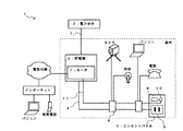
図1に示されるように、本発明に係る遠隔電源管理装置1は、電力会社2が提供する屋外の商用電力線3からの電力を屋内電力配線4に分配する配電盤5と、屋内の1以上の箇所に設置されたコンセントパネル6と、ルータ7とを備える。
As shown in FIG. 1, a remote power management device 1 according to the present invention includes a distribution board 5 that distributes power from an outdoor
配電盤5は、従来からあるものと同様に、屋外の電力量計(図示せず)を経て引き込み口(図示せず)から屋内に導入された商用電力線3に、電流ブレーカ、漏電ブレーカ等の安全器具(図示せず)が直列接続され、必要に応じ、その後段に複数の系統別ブレーカ(図示せず)が並列に設けられる。図1では、配電盤5から1つの部屋に対して1本の屋内電力配線4を布設してあるが、リビング、キッチン、寝室、脱衣室、階段等の複数の場所に対し複数本に分かれた屋内電力配線4を布設し、各屋内電力配線4を系統別ブレーカに接続するとよい。図1では、1本の屋内電力配線4に3つのコンセントパネル6が並列に設けられている。コンセントパネル6は、壁などに設置される。なお、3つのコンセントパネル6は全て同様か類似の構造であるが、1つのコンセントパネル6のみ正面外観を詳細に示してある。
The switchboard 5 is provided with a safety device such as a current breaker, a leakage breaker, etc. to a
1つのコンセントパネル6には、1つ以上の電力用コンセント8が設けられる。電力用コンセント8は、デジタル家電機器の電力ケーブルのプラグを挿入するものである。図中右端に大きく示したコンセントパネル6には1つしか電力用コンセント8が設けられていないが、2つ以上のデジタル家電機器が接続されているコンセントパネル6には2つ以上の電力用コンセント8が設けられる。
One outlet panel 6 is provided with one or
デジタル家電機器として、図1には、宅内セキュリティーカメラ、照明器具、パソコン、固定電話機が示されている。 As digital home appliances, FIG. 1 shows a home security camera, a lighting fixture, a personal computer, and a fixed telephone.
コンセントパネル6には、電力用コンセント8への電力供給をON/OFFする電子スイッチ22(図2参照)と、その電子スイッチと直列接続され、電子スイッチによる電力ON/OFFを反転させる手動電力ON/OFFスイッチ9と、対デジタル家電機器用の通信ケーブルコネクタ10とが設けられる。
The outlet panel 6 includes an electronic switch 22 (see FIG. 2) for turning on / off the power supply to the
通信ケーブルコネクタ10は、同軸ケーブルコネクタ、LANケーブルコネクタなどがよい。言うまでもないが、通信ケーブルコネクタ10は、デジタル家電機器が備えている通信ポートと互換性を有する。
The
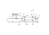
図2に示されるように、電力用コンセント8の電力回路21は、屋内電力配線4から電力用コンセント8に至る途中に、電子スイッチ22と手動電力ON/OFFスイッチ9とを直列に設けたものである。電子スイッチ22は、対応する電力用コンセント8への電力をON/OFFするもので、具体的には、半導体リレー、電磁リレーなどである。電子スイッチ22は、電力用コンセント8に繋がる配線の単極(課電側)に接点(半導体リレーの場合は仮想的な接点)が挿入される。接点は、配線の両極に挿入していわゆる両切りの回路を構成してもよい。手動電力ON/OFFスイッチ9も、同様に、配線の単極に接点が挿入される。
As shown in FIG. 2, the power circuit 21 of the
電子スイッチ22は、常に屋内電力配線4に導通している1つのコモン入力22cを接点の開閉により2つの出力22a,22bの一方に選択的に導通させるようになっている。電子スイッチ22は配電盤5内に設け、各電子スイッチ22から各電力用コンセント8まで個別に屋内電力配線4を布設してもよいが、ここではコンセントパネル6内に電子スイッチ22を設け、ルータ7から各電子スイッチ22まで接点駆動信号用の信号線(図示せず)を布設するものとする。
The electronic switch 22 is configured to selectively conduct one common input 22c that is always conducted to the
手動電力ON/OFFスイッチ9は、常に電力用コンセント8に導通している1つのコモン出力9cを接点の開閉により2つの入力9a,9bの一方に選択的に導通させるようになっている。
The manual power ON /
電子スイッチ22の出力22aと手動電力ON/OFFスイッチ9の入力9aとが接続されており、電子スイッチ22の出力22bと手動電力ON/OFFスイッチ9の入力9bとが接続されている。
The output 22a of the electronic switch 22 and the input 9a of the manual power ON /
手動電力ON/OFFスイッチ9は、コモン出力9cが2つの入力9a,9bのいずれかに導通する2つの状態のいずれかを機械的に保持するシーソースイッチ(オルタネーティブスイッチ)である。
The manual power ON /
図2の電力回路21は、電子スイッチ22の接点と手動電力ON/OFFスイッチ9の接点が図示の上側又は下側の同じ側に導通しているとき電力用コンセント8への電力供給がONされ、そうでないとき電力用コンセント8への電力供給がOFFされる回路である。手動電力ON/OFFスイッチ9には、電力用コンセント8への電力供給がONのとき点灯されるLED表示灯を設けてもよい。また、手動電力ON/OFFスイッチ9における接点が、コモン出力9cと入力9aが導通する状態か、コモン出力9cと入力9bが導通する状態かを検出するセンサを設け、そのセンサの出力をルータ7に接続してもよい。コモン出力9cと入力9aが導通する状態か、コモン出力9cと入力9bが導通する状態かを把握することで、外部からの切り替えが正確に、速く行うことができる。
In the power circuit 21 of FIG. 2, the power supply to the
この電力回路21には、屋内電力配線4から電力用コンセント8に流れる電流を測定する電流センサ23が設けられる。
The power circuit 21 is provided with a current sensor 23 that measures a current flowing from the
図1、図3に示されるように、ルータ7は、モジュラーケーブル、LANケーブル、光ケーブルなどで電話回線に接続可能、かつ、電話回線を介してインターネットに接続可能な通信中継機器である。また、ルータ7は、CPU、メモリ、キーボード、表示器などを備えたコンピュータ装置であり、適宜なソフトウェアを搭載したり、適宜なI/Oを接続することで所望する機能が実現できる。
As shown in FIGS. 1 and 3, the
本発明では、ルータ7内のI/Oポート(図示せず)に、各電子スイッチ22への接点駆動信号用の信号線(図示せず)が接続され、ルータ7内の通信ポート(図示せず)に、各電力用コンセント8に付随する通信ケーブルコネクタ10からの屋内通信線11が接続される。これらの信号線や屋内通信線11は、ルータ7から各電力用コンセント8まで屋内電力配線4と同様に壁内に埋設配線される。屋内通信線11は、同軸ケーブル、LANケーブルなどを用いる。
In the present invention, a signal line (not shown) for contact driving signals to each electronic switch 22 is connected to an I / O port (not shown) in the
本発明では、ルータ7は、電話回線を介して外部と電文を送受信する回線送受信部31と、受信した電文に含まれている所望のデジタル家電機器に対する電力ON/OFF指令を認識する指令認識部32と、各電力用コンセント8に接続されているデジタル家電機器の種類などを記憶する接続機器記憶部33と、上記電力ON/OFF指令を受けたデジタル家電機器が接続されている電力用コンセント8について上記電子スイッチ22のON/OFFを切り替える切り替え制御部34と、デジタル家電機器の通信による初期設定手順を機種ごとに記憶する初期設定手順記憶部35と、デジタル家電機器への電力供給がONになるよう上記電子スイッチ22を切り替えたときに当該デジタル家電機器用の初期設定手順の通信を行う屋内送受信部36とから構成され、主としてソフトウェアにより動作制御を行う。
In the present invention, the
さらに、ルータ7は、各電流センサ23が測定した電流を電力値に換算する電力測定部37と、該電力値を上記電力用コンセント8別に表示する表示部38とを主としてソフトウェアにより実現する。
Further, the
また、ルータ7は、現在電力用コンセント8で消費されている電力が待機電力かどうかを検出する待機電力検出部(図示せず)と、その待機電力が不要な待機電力かどうかを判定して待機電力の消費を制限する待機電力制限部(図示せず)とを主としてソフトウェアにより実現する。
Further, the
また、ルータ7は、所望のデジタル家電機器について電力をON/OFFする時刻を設定して記憶し、当該時刻になると当該デジタル家電機器が接続されている電力用コンセント8に対する電力ON/OFF指令を生成する電源タイマ部、所望のデジタル家電機器について動作を開始/停止する時刻を設定して記憶し、当該時刻になると当該デジタル家電機器に対して当該動作の開始/停止を指令するか又は、当該時刻になる前に当該デジタル家電機器に対して当該時刻における当該動作の開始/停止を予約する動作タイマ部を主としてソフトウェアにより実現する。
Also, the
回線送受信部31は、物理的には電話回線に接続されており、ダイヤルアップにより適宜なノードまで回線接続されると共に、論理的には上記ノードを介しインターネット上のプロバイダ(サーバ)に接続されるようになっている。
The line transmission /
一方、遠隔電源管理装置1のユーザは、携帯電話、ノートパソコン、デスクトップパソコンなどのモバイル機器から上記サーバを経由してルータ7にアクセス可能である。なお、アクセスに関して、ユーザが遠隔電源管理装置1の正当な管理者であることを認証するためにインターネットのアドレス、ユーザID、パスワード等を用いること、さらに、ユーザがデジタル家電機器の正当な管理者であることを認証するために機器ID、ユーザID、パスワード等を用いても良い。
On the other hand, a user of the remote power management apparatus 1 can access the
また、携帯電話からは、遠隔電源管理装置1に電話でアクセスすることもできる。この場合、電話会社が提供する番号通知機能を利用し、電話を掛けてきた相手の電話番号がユーザの携帯電話の電話番号かどうかをルータ7で判定して認証を行うとよい。
Also, the remote power management device 1 can be accessed from a mobile phone by telephone. In this case, the number notification function provided by the telephone company may be used to determine whether or not the telephone number of the other party who made the call is the telephone number of the user's mobile phone by the
回線送受信部31とモバイル機器との間で送受信される電文は、公知のインターネットのプロトコルに従って定型化される。本発明における電文は、こうした定型化された電文のユーザ欄に格納される。本発明における電文は、デジタル家電機器に対する種々の指令を含む。電力ON/OFF指令は、その一つである。電文は、カメラの視角を変更する指令、エアコンの設定温度を変更する指令、テレビ録画装置の予約をする指令なども含む。
A message transmitted and received between the line transmission /
指令認識部32は、種々のデジタル家電機器に対する種々の指令を電文中から抽出し、指令内容を解釈するようになっている。指令には、デジタル家電機器の種類、機器ID、指令コードなどが含まれる。指令コードは、デジタル家電機器が本来から使用しているコードでもよいし、外部からの通信には本発明の遠隔電源管理装置1に特有のコードを使用し、デジタル家電機器が本来から使用しているコードとの変換手段を指令認識部32に設けておいて、指令認識部32で変換するようにしてもよい。
The
接続機器記憶部33は、電力用コンセント8のID番号とデジタル家電機器のID番号とを対応付けて記憶することにより、各電力用コンセント8に接続されているデジタル家電機器を記憶するようになっている。対応付けは、ユーザがデジタル家電機器を部屋に設置するときに、遠隔電源管理装置1を操作して行う。
The connected device storage unit 33 stores the digital home appliance connected to each
切り替え制御部34は、電力ON/OFF指令を受けたデジタル家電機器が接続されている電力用コンセント8について電子スイッチ22のON/OFFを切り替えるものである。
The switching
電力ON/OFF指令が単なるトグル(現状を反転させる)を目的とする指令である場合、切り替え制御部34は電子スイッチ22を単にトグル動作させればよい。つまり、図2の回路において、電子スイッチ22の接点が上側にあって、かつ、手動電力ON/OFFスイッチ9の接点が上側にあるとき、電力はONである。電子スイッチ22を一度トグル動作させると接点が下側に切り替わって電力はOFFとなる。電子スイッチ22をもう一度トグル動作させると接点が上側に切り替わって電力はONとなる。しかし、手動電力ON/OFFスイッチ9が下側に切り替えられると、電子スイッチ22の接点の上下と電力ON/OFFの関係は逆転する。
When the power ON / OFF command is a command intended for simple toggle (reversing the current state), the switching
電力ON/OFF指令がデジタル家電機器に与える電力を明確にONにするための指令(又はOFFにするための指令)である場合、切り替え制御部34は手動電力ON/OFFスイッチ9と電子スイッチ22との接続状態を、内蔵するセンサを用いて検出した上で、電子スイッチ22を切り替えることになる。
When the power ON / OFF command is a command for clearly turning on the power to be applied to the digital home appliance (or a command for turning it OFF), the switching
初期設定手順記憶部35は、デジタル家電機器の通信による初期設定手順を機種ごとに記憶するものである。初期設定の例として、時計(カレンダ機能)の初期設定がある。時計の初期設定項目としては、年、月、日、持、分、秒などがある。初期設定手順記憶部35は、これらの項目を設定する順序、デジタル家電機器における初期のデフォルト値などを記憶する。記憶は、ユーザがデジタル家電機器を部屋に設置するときに、遠隔電源管理装置1を操作して行う。
The initial setting
屋内送受信部36は、デジタル家電機器への電力供給がONになるよう電子スイッチ22を切り替えたときに当該デジタル家電機器用の初期設定手順の通信を行うものである。電子スイッチ22を切り替えたときに、電力供給がONになったかOFFになったかの判定論理は、上記切り替え制御部34の説明に準じる。
The indoor transmission / reception unit 36 performs communication of an initial setting procedure for the digital home appliance when the electronic switch 22 is switched so that power supply to the digital home appliance is turned on. The determination logic as to whether the power supply is turned on or off when the electronic switch 22 is switched follows the description of the switching
電力測定部37は、各電力用コンセント8の電流センサ23が測定した電流をデジタル値に変換し、この電流値に商用電力の電圧値を掛けて電力値を求めるものである。
The power measuring unit 37 converts the current measured by the current sensor 23 of each
表示部38は、後述する表示器42に電力用コンセント8ごとの電力値を表示させるものである。
The display unit 38 displays a power value for each
ルータ7は、配電盤5に内蔵されてもよいし、配電盤5とは別筐体に形成し、配電盤5の近傍に取り付けてもよい。また、ルータ7は、屋内の任意の場所に設置されてもよい。
The
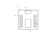
図4に示した配電盤5は、ルータ7(図4には図示せず)を内蔵したものである。配電盤5の筐体の正面には、メインブレーカ41とルータ7の表示器42が配置される。さらに、この筐体の正面には、電力用コンセント8の手動電力ON/OFFスイッチ9と直列接続される配電盤側手動電力ON/OFFスイッチ43が設けられる。さらに、配電盤5の筐体の内部には、電子スイッチ22が設けられてもよい。表示器42は、液晶パネルで構成してもよい。また、表示器42は、ルータ7のキーボードを兼ねたタッチパネルで構成してもよい。
The switchboard 5 shown in FIG. 4 includes a router 7 (not shown in FIG. 4). A main breaker 41 and a display 42 of the
図5は、遠隔電源管理装置1において各種設定を行うときの表示器42の表示内容を示す図である。 FIG. 5 is a diagram illustrating display contents of the display 42 when various settings are performed in the remote power management device 1.
図示のように、表示器42には、デジタル家電機器の名称表示枠51が表示され、名称表示枠51内に電力用コンセント8の番号「1」、「2」、「3」とその電力用コンセント8に接続されているデジタル家電機器の名称とが表示される。ここでは、単に「冷蔵庫」、「テレビ」と表示しているが、同種のデジタル家電機器が複数存在する場合には、個体が識別できる名称をユーザが任意に与えるものとする。
As shown in the drawing, a
ユーザは、表示器42上の適宜な名称表示枠を選択した後、ルータ7の図示しないキーボード(又はタッチパネル)からデジタル家電機器の名称を入力する。その内容が接続機器記憶部33に設定される。このように、電力用コンセント8とデジタル家電機器の対応付けは簡単に入力操作でき、変更も簡単である。
After selecting an appropriate name display frame on the display 42, the user inputs the name of the digital home appliance from a keyboard (or touch panel) (not shown) of the
ユーザは、表示器42に表示させた電力用コンセント8について、月間消費電力(又は毎日の消費電力)の管理や目標消費電力の設定を行うことができる。このために、ルータ7は、月間の消費電力を積算し毎月の消費電力を統計する電力統計部、月間の目標となる消費電力を設定し記憶する目標消費電力設定部、月間消費電力が目標消費電力を超過したときにアラームを発生させるアラーム発生部、当日までの月間消費電力が目標消費電力を超過したときにあらかじめ設定してあるデジタル家電機器に対する電力供給を減少させるか停止する電力超過制限部、毎月の消費電力や目標消費電力を数値、グラフなどで表示する表示部などを備える。さらに、ルータ7は、当月の途中において当月の初日から当日までの統計結果に基づいて当月の末日までの消費電力を予想する消費電力予想部、統計した消費電力や消費電力の予想に基づいて電力料金や予想電力料金を算出する電力料金算出部などを備える。
The user can manage monthly power consumption (or daily power consumption) and set target power consumption for the
電力超過制限部において、当日までの月間消費電力が目標消費電力を超過したときにあらかじめ設定してあるデジタル家電機器に対する電力供給を減少させる方法として、例えば、夏期におけるエアコンの室内温度設定が18℃であるときに、当日までの月間消費電力が目標消費電力を超過すると、室内温度設定をそれ以前より高い温度、例えば、20℃に変更するという方法がある。 As a method of reducing the power supply to the digital home appliance set in advance when the monthly power consumption up to the day exceeds the target power consumption in the power excess limiting unit, for example, the indoor temperature setting of the air conditioner in summer is 18 ° C. When the monthly power consumption up to the current day exceeds the target power consumption, there is a method of changing the room temperature setting to a higher temperature than before, for example, 20 ° C.
ユーザは、ルータ7内のタイマ(電源タイマ部、動作タイマ部)を設定することができる。タイマは、デジタル家電機器の電力ON/OFFの時刻(電力用コンセント8における電力ON/OFFの時刻)、デジタル家電機器の各種動作の開始/停止時刻などをメモリに記憶し、これらの設定時刻を内蔵時計が示す現在時刻と照合することによりデジタル家電機器の電力ON/OFFと動作を管理する。
The user can set timers (power timer unit, operation timer unit) in the
ユーザは、モバイル機器からルータ7に指令を与えることができる項目をあらかじめ設定することができる。これにより、所望のデジタル家電機器あるいはルータ7自身に対してモバイル機器から指令を出そうとしたとき、その指令の項目があらかじめ設定されたものでなければ、指令を受け付けないようにできる。
The user can set in advance items that can give commands to the
以下、遠隔電源管理装置1の動作を説明する。 Hereinafter, the operation of the remote power management device 1 will be described.
図6に示されるように、コンセントパネル6の電力用コンセント8にDVDレコーダ61の電力ケーブル62が接続されている。コンセントパネル6の通信ケーブルコネクタ10にDVDレコーダ61の通信ケーブル63が接続されている。手動電力ON/OFFスイッチ9は図示省略している。
As shown in FIG. 6, the power cable 62 of the DVD recorder 61 is connected to the
今、図2に示した電力用コンセント8内の電力回路21において、電子スイッチ22と手動電力ON/OFFスイッチ9の接点の組み合わせにより、電力用コンセント8への電力供給がOFFされているものとする。このとき、図6のDVDレコーダ61は全く電力の供給を受けていないので、主電源の電力がOFFであることはもちろん、待機電力も停止されている。DVDレコーダ61の時計機能は、時刻がリセットされている。
Now, in the power circuit 21 in the
一方、遠隔電源管理装置1には、電源タイマ部にDVDレコーダ61が接続されている電力用コンセント8への電力供給をONする時刻が記憶されていると共に、初期設定手順記憶部35にDVDレコーダ61の通信による初期設定手順が記憶されているものとする。
On the other hand, the remote power management device 1 stores the time to turn on the power supply to the
所定の時刻になると、遠隔電源管理装置1の電源タイマ部は、DVDレコーダ61が接続されている電力用コンセント8に対する電力ON/OFF指令を生成する。切り替え制御部34は、上記電力ON/OFF指令を受けたデジタル家電機器が接続されている電力用コンセント8について電子スイッチ22のON/OFFを切り替える。これにより、電力用コンセント8への電力供給がONになる。
At a predetermined time, the power timer unit of the remote power management device 1 generates a power ON / OFF command for the
このようにして、ルータ7が出した指令によってDVDレコーダ61の電力がONになる。続いて、ルータ7は、DVDレコーダ61の時刻を設定する。すなわち、初期設定手順記憶部35にDVDレコーダ61の初期設定手順が記憶されている。屋内送受信部36は、屋内通信線11、通信ケーブルコネクタ10、通信ケーブル63を介してDVDレコーダ61と通信を行い、年、月、日、持、分、秒などの設定の初期設定手順を実行する。
In this way, the power of the DVD recorder 61 is turned on by a command issued by the
DVDレコーダ61は、通信によって初期設定が行われ、時刻が設定されるので、時計機能が動作を開始する。ここで、DVDレコーダ61が不揮発メモリに予約内容を保持している場合、その予約の実行が可能となる。 Since the DVD recorder 61 is initially set by communication and the time is set, the clock function starts its operation. Here, when the DVD recorder 61 holds the reservation contents in the nonvolatile memory, the reservation can be executed.
DVDレコーダ61が予約内容を保持していない場合(ユーザがDVDレコーダ61に予約をしていない場合も含む)であっても、ルータ7に設けられている接続機器記憶部33などDVDレコーダ61の予約が設定してあれば、その予約の実行が可能となる。すなわち、遠隔電源管理装置1の動作タイマ部は、DVDレコーダ61について録画などの動作を開始/停止する時刻を設定して記憶しており、当該時刻になるとDVDレコーダ61に対して当該動作の開始/停止を指令するか又は、当該時刻になる前(DVDレコーダ61の予約締め切り時刻前)にDVDレコーダ61に対して当該時刻での当該動作の開始/停止を予約する。
Even when the DVD recorder 61 does not hold the reservation contents (including the case where the user has not reserved the DVD recorder 61), the DVD recorder 61 such as the connected device storage unit 33 provided in the
以上説明したように、本発明によれば、遠隔電源管理装置1が電源タイマ部に設定されている時刻に、所望のデジタル家電機器が接続されている電力用コンセント8に電力を供給すると共に、宅内での通信によりデジタル家電機器の初期設定を行うので、デジタル家電機器の待機電力が停止したとき、デジタル家電機器の時刻がリセットされても支障がない。
As described above, according to the present invention, at the time when the remote power management device 1 is set in the power timer unit, power is supplied to the
図6では、予約による電力ONの動作を説明したが、予約による電力OFFの動作については自明であるから、説明は省く。また、図6では、遠隔電源管理装置1が予約に基づいて電力ONの指令を生成したが、モバイル機器からの指令によって電力ONを行うことができる。 In FIG. 6, the operation of turning on power by reservation has been described, but the operation of turning off power by reservation is self-explanatory, and thus description thereof is omitted. In FIG. 6, the remote power management device 1 generates a power-on command based on the reservation, but the power-on can be performed by a command from the mobile device.
モバイル機器が電文に所望のデジタル家電機器に対する電力ONの指令を格納し、その電文を遠隔電源管理装置1宛てに送信すると、回線送受信部31はこの電文を受信し、指令認識部32は指令を電文中から抽出し、指令内容を解釈する。接続機器記憶部33により、当該デジタル家電機器が接続されている電力用コンセント8が判明し、切り替え制御部34がその電力用コンセント8の電子スイッチ22のON/OFFを切り替える。続いて、初期設定手順記憶部35と屋内送受信部36により、当該デジタル家電機器の初期設定が実行される。
When the mobile device stores a power ON command for a desired digital home appliance in a message and transmits the message to the remote power management device 1, the
その後、モバイル機器において当該デジタル家電機器の動作指令を電文で送信することにより、当該デジタル家電機器を遠隔操作することもできる。例えば、宅内セキュリティーカメラの視角を変更したりすることがこれまで説明した装置構成により実現可能となる。 Then, the digital home appliance can be remotely operated by transmitting an operation command of the digital home appliance in a telegram in the mobile device. For example, changing the viewing angle of the home security camera can be realized by the apparatus configuration described so far.
次に、ユーザが手動電力ON/OFFスイッチ9を操作して電力用コンセント8への電力供給をONする態様を説明する。
Next, a mode in which the user turns on the power supply to the
今、図2に示した電力用コンセント8の電力回路21において、電子スイッチ22と手動電力ON/OFFスイッチ9の接点の組み合わせにより、電力用コンセント8への電力供給がOFFされているものとする。このとき、図6のDVDレコーダ61は全く電力の供給を受けていないので、主電源の電力がOFFであることはもちろん、待機電力も停止されている。DVDレコーダ61の時計機能は、時刻がリセットされている。
Now, in the power circuit 21 of the
続いて、手動電力ON/OFFスイッチ9の接点が反対側に切り替わると、電力用コンセント8への電力供給がONされる。よって、DVDレコーダ61の電力がONになる。DVDレコーダ61の初期設定はユーザが手動で行うことができる。
Subsequently, when the contact of the manual power ON /
ユーザは、DVDレコーダ61等のデジタル家電機器の電力を手動電力ON/OFFスイッチ9の操作でONした後に手動でOFFするとき、手動電力ON/OFFスイッチ9を操作するのが好ましい。デジタル家電機器の電源スイッチをOFFしたのでは待機電力は停止できないが、手動電力ON/OFFスイッチ9を切り替えれば電力用コンセント8への電力供給がOFFされるからである。
The user preferably operates the manual power ON /
ユーザは、デジタル家電機器の電力を手動電力ON/OFFスイッチ9の操作でONした後には、手動電力ON/OFFスイッチ9の操作でOFFしておくのが好ましい。電力用コンセント8への電力供給がONの状態のまま放置しておくと、電力が消費されるのはもちろんのこと、その後、モバイル機器からの遠隔操作又は電源タイマ部によって電子スイッチ22が切り替えられたとき、電力用コンセント8への電力供給がOFFになるからである。ただし、サーバ7が手動電力ON/OFFスイッチ9の接点の状態を検出してから電子スイッチ22を切り替えるようにすれば、電力用コンセント8への電力供給を間違いなくON又はOFFさせることができる。
It is preferable that the user turns off the power of the digital home appliance by operating the manual power ON /
1 遠隔電源管理装置
4 屋内電力配線
5 配電盤
6 コンセントパネル
7 ルータ
8 電力用コンセント
9 手動電力ON/OFFスイッチ
10 通信ケーブルコネクタ
11 屋内通信線
22 電子スイッチ
23 電流センサ
31 回線送受信部
32 指令認識部
33 接続機器記憶部
34 切り替え制御部
35 初期設定手順記憶部
36 屋内送受信部
37 電力測定部
38 表示部
DESCRIPTION OF SYMBOLS 1 Remote power
Claims (5)
各電力用コンセントに接続されているデジタル家電機器を記憶する接続機器記憶部と、所望のデジタル家電機器が接続されている電力用コンセントについて上記電子スイッチのON/OFFを切り替える切り替え制御部と、
デジタル家電機器の通信による初期設定手順を機種ごとに記憶する初期設定手順記憶部と、デジタル家電機器への電力供給がONになるよう上記電子スイッチを切り替えたときに当該デジタル家電機器用の初期設定手順の通信を行う屋内送受信部と、
該屋内送受信部から各通信ケーブルコネクタまで屋内配線された屋内通信配線とを備えたことを特徴とする遠隔電源管理装置。 A distribution board that distributes power from outdoor commercial power lines to indoor power wiring, outlet panels installed at one or more indoor locations, one or more power outlets for each outlet panel, and for each power One or more electronic switches that individually turn ON / OFF the power supply to the outlet, and a communication cable connector for digital household electrical appliances provided on the outlet panel for each of the power outlets;
A connection device storage unit that stores digital home appliances connected to each power outlet, a switching control unit that switches ON / OFF of the electronic switch for a power outlet to which a desired digital home appliance is connected, and
An initial setting procedure storage unit that stores an initial setting procedure by communication of the digital home appliance for each model, and an initial setting for the digital home appliance when the electronic switch is switched so that power supply to the digital home appliance is turned on. An indoor transceiver that communicates the procedure;
A remote power management device comprising: indoor communication wiring that is wired indoors from the indoor transceiver unit to each communication cable connector.
Priority Applications (1)
| Application Number | Priority Date | Filing Date | Title |
|---|---|---|---|
| JP2008099505A JP2009254146A (en) | 2008-04-07 | 2008-04-07 | Remote power supply management device |
Applications Claiming Priority (1)
| Application Number | Priority Date | Filing Date | Title |
|---|---|---|---|
| JP2008099505A JP2009254146A (en) | 2008-04-07 | 2008-04-07 | Remote power supply management device |
Publications (1)
| Publication Number | Publication Date |
|---|---|
| JP2009254146A true JP2009254146A (en) | 2009-10-29 |
Family
ID=41314276
Family Applications (1)
| Application Number | Title | Priority Date | Filing Date |
|---|---|---|---|
| JP2008099505A Pending JP2009254146A (en) | 2008-04-07 | 2008-04-07 | Remote power supply management device |
Country Status (1)
| Country | Link |
|---|---|
| JP (1) | JP2009254146A (en) |
Cited By (2)
| Publication number | Priority date | Publication date | Assignee | Title |
|---|---|---|---|---|
| WO2011058761A1 (en) * | 2009-11-12 | 2011-05-19 | パナソニック株式会社 | Power controller for electric devices, and telephone |
| JP2014201398A (en) * | 2013-04-04 | 2014-10-27 | 金剛株式会社 | Automatic library |
-
2008
- 2008-04-07 JP JP2008099505A patent/JP2009254146A/en active Pending
Cited By (3)
| Publication number | Priority date | Publication date | Assignee | Title |
|---|---|---|---|---|
| WO2011058761A1 (en) * | 2009-11-12 | 2011-05-19 | パナソニック株式会社 | Power controller for electric devices, and telephone |
| JPWO2011058761A1 (en) * | 2009-11-12 | 2013-03-28 | パナソニック株式会社 | Electric equipment power control device and telephone |
| JP2014201398A (en) * | 2013-04-04 | 2014-10-27 | 金剛株式会社 | Automatic library |
Similar Documents
| Publication | Publication Date | Title |
|---|---|---|
| JP6306727B2 (en) | Smart home scene switching method and system | |
| JP5173369B2 (en) | Power management system | |
| US20120221164A1 (en) | Power controller for electric devices, and telephone | |
| JP2010213367A (en) | Energy saving system using ubiquitous sensor and intelligent table tap | |
| KR101077016B1 (en) | Power saving multi-tab and control system thereof | |
| JP2006025474A (en) | Method for managing power supply to electric apparatus and power management network system | |
| CN202230364U (en) | Remote control system of household device | |
| US20160349734A1 (en) | Operation apparatus and operation method | |
| CN201707569U (en) | Intelligent residence control terminal | |
| JP2007129661A (en) | Outlet control system | |
| WO2014171000A1 (en) | Power management system and terminal device | |
| JP5173368B2 (en) | Power management system | |
| JP2009254146A (en) | Remote power supply management device | |
| KR100634448B1 (en) | Method for remote power control and apparatus thereof | |
| KR20090071456A (en) | Standby power control system using a home-network | |
| KR100511621B1 (en) | Home network system by electric charging equipment of mobile telecommunication terminal and the same control method | |
| CN110941198A (en) | Storage medium, smart panel and power-saving booting method thereof | |
| US10084610B2 (en) | Control apparatus and control method | |
| KR20070097901A (en) | System and method for management a water purifier using home network | |
| CN111123718A (en) | Storage medium, intelligent panel and power-saving management method thereof | |
| KR100990131B1 (en) | System for controlling standby power | |
| KR101103099B1 (en) | A measuring instrument to have an cutoff mean of optional electricity | |
| AU2016336004B2 (en) | Home automation system device power optimization | |
| KR20060115113A (en) | Home-gateway with power control function | |
| US20220385496A1 (en) | Control system and control method |