JP2009252142A - Data processing apparatus - Google Patents
Data processing apparatus Download PDFInfo
- Publication number
- JP2009252142A JP2009252142A JP2008102392A JP2008102392A JP2009252142A JP 2009252142 A JP2009252142 A JP 2009252142A JP 2008102392 A JP2008102392 A JP 2008102392A JP 2008102392 A JP2008102392 A JP 2008102392A JP 2009252142 A JP2009252142 A JP 2009252142A
- Authority
- JP
- Japan
- Prior art keywords
- data
- compression
- data processing
- circuit
- result
- Prior art date
- Legal status (The legal status is an assumption and is not a legal conclusion. Google has not performed a legal analysis and makes no representation as to the accuracy of the status listed.)
- Granted
Links
Images


Classifications
-
- G—PHYSICS
- G06—COMPUTING; CALCULATING OR COUNTING
- G06F—ELECTRIC DIGITAL DATA PROCESSING
- G06F21/00—Security arrangements for protecting computers, components thereof, programs or data against unauthorised activity
- G06F21/50—Monitoring users, programs or devices to maintain the integrity of platforms, e.g. of processors, firmware or operating systems
- G06F21/52—Monitoring users, programs or devices to maintain the integrity of platforms, e.g. of processors, firmware or operating systems during program execution, e.g. stack integrity ; Preventing unwanted data erasure; Buffer overflow
- G06F21/54—Monitoring users, programs or devices to maintain the integrity of platforms, e.g. of processors, firmware or operating systems during program execution, e.g. stack integrity ; Preventing unwanted data erasure; Buffer overflow by adding security routines or objects to programs
-
- G—PHYSICS
- G06—COMPUTING; CALCULATING OR COUNTING
- G06F—ELECTRIC DIGITAL DATA PROCESSING
- G06F21/00—Security arrangements for protecting computers, components thereof, programs or data against unauthorised activity
- G06F21/50—Monitoring users, programs or devices to maintain the integrity of platforms, e.g. of processors, firmware or operating systems
- G06F21/52—Monitoring users, programs or devices to maintain the integrity of platforms, e.g. of processors, firmware or operating systems during program execution, e.g. stack integrity ; Preventing unwanted data erasure; Buffer overflow
-
- G—PHYSICS
- G06—COMPUTING; CALCULATING OR COUNTING
- G06F—ELECTRIC DIGITAL DATA PROCESSING
- G06F21/00—Security arrangements for protecting computers, components thereof, programs or data against unauthorised activity
- G06F21/70—Protecting specific internal or peripheral components, in which the protection of a component leads to protection of the entire computer
- G06F21/71—Protecting specific internal or peripheral components, in which the protection of a component leads to protection of the entire computer to assure secure computing or processing of information
Landscapes
- Engineering & Computer Science (AREA)
- Computer Security & Cryptography (AREA)
- Theoretical Computer Science (AREA)
- Software Systems (AREA)
- Computer Hardware Design (AREA)
- Physics & Mathematics (AREA)
- General Engineering & Computer Science (AREA)
- General Physics & Mathematics (AREA)
- Mathematical Physics (AREA)
- Storage Device Security (AREA)
Abstract
Description
本発明は、例えば映像、音楽データや個人情報など金銭的に価値あるデータを安全に運用するためのデータ処理装置に関する。 The present invention relates to a data processing apparatus for safely operating financially valuable data such as video, music data and personal information.
近年の半導体技術の発展に伴って、音楽データがレコードからCD(Compact Disc)へ、映画データがビデオからDVD(Digital Versatile Disc)へと、データのデジタル化が急速に進んでいる。著作権を伴うデータや個人情報などのデジタルデータは、コピーによる品質劣化がないという制作者や購入者にとっての長所がある一方、違法コピーによる販売数量の減少や不特定多数への個人情報の漏洩などの短所がある。このように、デジタルコンテンツは許可された者のみが使用可能となる仕組みが必要である。 With the development of semiconductor technology in recent years, digitization of data is rapidly progressing from music data to CD (Compact Disc) and movie data from video to DVD (Digital Versatile Disc). While copyrighted data and digital data such as personal information have the advantage for producers and purchasers that there is no quality degradation due to copying, the sales volume decreases due to illegal copying and leakage of personal information to unspecified majority There are disadvantages. Thus, a mechanism is required that allows digital content to be used only by authorized persons.
デジタルコンテンツや通信、金融などの価値あるデータを悪意の第三者から保護するために、暗号技術が積極的に利用されている。暗号技術によって、使用者がコンテンツの利用を許可されているのかを確認するための認証機能や、許可された者のみがコンテンツを利用可能とするためのデータ暗号化・復号機能が実現されている。このような暗号技術を半導体製品に実装することによって、デジタルコンテンツなどの処理システムが実現されている。 Cryptographic technology is actively used to protect valuable data such as digital content, communications, and finance from malicious third parties. Cryptographic technology realizes an authentication function for confirming whether a user is permitted to use content, and a data encryption / decryption function for enabling only authorized users to use the content . A processing system for digital content and the like is realized by mounting such encryption technology on a semiconductor product.
従来のデジタルコンテンツ処理システムでは、DVDドライブなどの暗号化コンテンツを出力する装置、コンテンツ処理装置、コンテンツ記録媒体との間で認証が行われ、認証処理が正当であることが確認されると暗号化コンテンツがコンテンツ記録媒体からコンテンツ処理装置へと伝送される。暗号化コンテンツを復号するためには鍵が必要であり、鍵はコンテンツ記録媒体における鍵の生成に必要な情報と固有情報とから計算により生成される。固有情報およびコンテンツ復号鍵の計算過程で生成された一時データや鍵は、これらを不正に取得することによって暗号化コンテンツを不正に復号することができるため秘匿性が求められる。 In a conventional digital content processing system, authentication is performed between a device that outputs encrypted content such as a DVD drive, a content processing device, and a content recording medium, and encryption is performed when it is confirmed that the authentication processing is valid. The content is transmitted from the content recording medium to the content processing apparatus. A key is required to decrypt the encrypted content, and the key is generated by calculation from information necessary for generating the key in the content recording medium and unique information. The temporary data and key generated in the process of calculating the unique information and the content decryption key are required to be concealed because the encrypted content can be decrypted illegally by obtaining them.
このように、悪意の第三者からコンテンツを不正に利用されないようにするために、コンテンツ処理装置にセキュリティ保護領域を設ける必要があるが、セキュリティ保護領域に対して悪意の第三者が何らかの影響を与え得る場合では、認証やコンテンツの復号処理を行うことによってコンテンツの秘匿性やドライブとの認証結果が保障されるわけではない。例えば、コンテンツ処理装置はCPU(Central Processing Unit)によってソフトウェアで制御されているため、デバッガを接続することで認証結果の改ざんや固有情報の不正取得などが容易となり、不正なアクセスが可能になるとセキュリティ保護領域に直接データを送信することで認証等を無効化することができる。従って、このようなコンテンツ処理システムでは、セキュリティ保護領域内の機能を外部から不正にアクセスできないような構成にする必要がある。具体的には、セキュリティ保護領域内の機能を1チップ化してCPUへのデバッガの接続を不可能にし、外部から不正にデータの書き込み・読み出しをできないようにするなどの対策が必要となる。 As described above, in order to prevent unauthorized use of content by a malicious third party, it is necessary to provide a security protection area in the content processing apparatus, but the malicious third party has some influence on the security protection area. In such a case, the confidentiality of the content and the authentication result with the drive are not guaranteed by performing the authentication or the content decrypting process. For example, since the content processing apparatus is controlled by software by a CPU (Central Processing Unit), it is easy to tamper with the authentication result or illegally acquire specific information by connecting a debugger. Authentication or the like can be invalidated by sending data directly to the protected area. Therefore, such a content processing system needs to be configured so that functions in the security protection area cannot be illegally accessed from the outside. Specifically, it is necessary to take measures such as making the functions in the security protection area into one chip, making it impossible to connect the debugger to the CPU, and preventing unauthorized data writing / reading from the outside.
従来では、データプロセッサが命令フローの所定区間毎に区間に含まれる命令に対するサム値を演算し、同一区間において前回の演算で得られたサム値と今回の演算で得られたサム値とが不一致であれば、命令の実行を停止、または命令の実行順序を強制的に変更するものがある(例えば、特許文献1参照)。また、ゲームプログラムから抽出した分岐命令と、非分岐命令と、非分岐命令のチェックサムとを圧縮し、当該圧縮データを暗号化してプログラムメモリに格納する暗号プログラム生成装置がある(例えば、特許文献2参照)。 Conventionally, the data processor calculates the sum value for the instructions included in each interval of the instruction flow, and the sum value obtained by the previous operation does not match the sum value obtained by the current operation in the same interval. If so, there is one that stops execution of instructions or forcibly changes the execution order of instructions (see, for example, Patent Document 1). Also, there is an encryption program generation device that compresses a branch instruction extracted from a game program, a non-branch instruction, and a checksum of the non-branch instruction, encrypts the compressed data, and stores it in a program memory (for example, Patent Documents) 2).
発明者による検討では、これらの特許文献に記載の発明では、たとえプログラムを改ざんしたとしてもサム値のチェックを行う比較処理を無効化され、またはプログラム自体は改ざんせず当該プログラムで処理するデータを改ざんされた場合には、実質的にセキュリティ保護が無効となる問題が生じることが明らかとなった。 According to the inventor's study, in the inventions described in these patent documents, even if the program is tampered with, the comparison process for checking the sum value is invalidated, or the program itself does not tamper with the data processed by the program. It has been revealed that there is a problem that security protection is effectively invalidated if tampered.
また、従来のコンテンツ処理装置では、セキュリティホールの存在箇所が分からないため、セキュリティホールが発見された時点で回収や再設計が必要となり、コストの増大や製品の信頼性の低下などの問題が生じてしまう。 In addition, since conventional content processing devices do not know where security holes exist, they must be collected and redesigned when a security hole is discovered, resulting in problems such as increased costs and reduced product reliability. End up.
セキュリティ保護領域のハードウェアに対する改ざんは、比較的高価な装置と高度な知識を有する者しか行えないため第三者に改ざんされる問題は少ないが、処理結果の改ざんなどセキュリティ処理に係わるソフトウェアに対する改ざんは安価であり効果も大きい。従来は、ソフトウェアに対する改ざんを検出することができなかったため、データの秘匿性や正当性を保証するためには制御ソフトウェアが改ざんされた場合において生じる問題を推定し、安全性を確保する何らかの手段をハードウェアに実装しておく必要があった。しかし、特許文献1に示すようなデータプロセッサとすると、システムが複雑になるにつれてソフトウェアのサイズが増大して改ざんによる問題点も増加・拡散してしまうため、改ざんによって生じる全ての問題について対策できたかの判断が難しく確認に時間がかかってしまう。また、生じた問題を見逃していた場合は、問題が生じるごとにハードウェアの追加や変更が必要となるため時間やコストがかかる。改ざんを検出するために、パリティやエラー訂正技術を用いる方法があるが、ハミング距離を大きく越えた場合に改ざんが検出できないことや、エラー検出するための専用のハードウェアが必要となるなど不都合なことも多い。
Tampering with hardware in the security protection area can be performed only by a relatively expensive device and someone with advanced knowledge, so there are few problems with tampering with third parties, but tampering with software related to security processing such as tampering with processing results. Is inexpensive and highly effective. Previously, it was not possible to detect tampering with the software. Therefore, in order to guarantee the confidentiality and correctness of the data, a problem that occurs when the control software is tampered with is estimated, and some means for ensuring safety is used. It had to be implemented in hardware. However, if the data processor as shown in
一方、秘匿データを一時保存する場合において、データに対して暗号化および署名生成をしておけば、データを使用する際に署名検証を行うことによってデータの改ざんを検出することができる。しかし、過去に生成された暗号データおよび署名がある場合には、これらを別の機会に生成された暗号データおよび署名に摩り替えられることを防止する必要がある。つまり、データの書き換えなどの不正利用を防止しなければならない。特許文献2に示すプログラム生成装置では、プログラムメモリに格納された命令が改ざんされたことは検出できるが、命令が実行されているときには命令の異常を検出できなかった。このように、データの書き換えを検出することができなかったため、データが書き換えられたまま処理が行なわれていた。そのため、データの書き換えによってコンテンツが不正に再生されるなどの問題があった。このような問題の発生は状況によって変化するため、全ての不正行為を防止することが難しいという問題がある。
On the other hand, when secret data is temporarily stored, if data is encrypted and a signature is generated, tampering of the data can be detected by performing signature verification when using the data. However, when there are encrypted data and signatures generated in the past, it is necessary to prevent them from being transferred to encrypted data and signatures generated at another opportunity. In other words, unauthorized use such as data rewriting must be prevented. In the program generation device shown in
本発明は、これらの問題を解決するためになされたもので、データに対するソフトウェアの改ざんやデータの書き換えを検出するデータ処理装置を提供することを目的とする。 The present invention has been made to solve these problems, and it is an object of the present invention to provide a data processing apparatus that detects software tampering or data rewriting on data.
上記の課題を解決するために、本発明の一実施形態によるデータ処理装置は、秘匿データを含む暗号化された信号を復号するための暗号手段を有するセキュリティ装置を備え、セキュリティ装置は、セキュリティ装置にアクセスする際に使用される信号であるアクセス信号を圧縮し、圧縮結果を出力する圧縮手段と、圧縮手段から出力された圧縮結果と、予め求められたアクセス信号の圧縮結果の期待値とを比較する比較手段とを備えることを特徴とする。 In order to solve the above problem, a data processing device according to an embodiment of the present invention includes a security device having an encryption unit for decrypting an encrypted signal including confidential data, and the security device is a security device. The compression means for compressing the access signal, which is a signal used when accessing the network, and outputting the compression result, the compression result output from the compression means, and the expected value of the compression result of the access signal obtained in advance Comparing means for comparing is provided.
本発明の一実施形態では、秘匿データを含む暗号化された信号を復号するための暗号手段を有するセキュリティ装置を備え、セキュリティ装置は、セキュリティ装置にアクセスする際に使用される信号であるアクセス信号を圧縮し、圧縮結果を出力する圧縮手段と、圧縮手段から出力された圧縮結果と、予め求められたアクセス信号の圧縮結果の期待値とを比較する比較手段とを備えるため、データに対するソフトウェアの改ざんやデータの書き換えを検出することができる。 In one embodiment of the present invention, a security device having an encryption unit for decrypting an encrypted signal including confidential data is provided, and the security device is an access signal that is a signal used when accessing the security device. And a comparison unit that compares the compression result output from the compression unit with the expected value of the compression result of the access signal obtained in advance. Tampering and data rewriting can be detected.
本発明の実施形態について、図面を用いて以下に説明する。 Embodiments of the present invention will be described below with reference to the drawings.
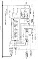
図1は、本発明の実施形態によるデータ処理装置1のブロック図である。図1に示すように、データ処理装置1は、データ処理装置1の各機能を制御するCPU2と、CPU2のプログラムや暗号化固有情報10などのデータを格納するための不揮発メモリ3と、コンテンツ記録媒体からデータを受信するためのATAPI(AT Attachment Packet Interface)などの入力I/F(インターフェース)回路4と、CPU2の一時データおよび暗号化コンテンツを一時保存するためのRAM5と、秘匿データを含む暗号化された信号を復号するための暗号回路9(暗号手段)を有するセキュリティ装置6と、復号されたコンテンツを復調するためのMPEG(Moving Picture Experts Group)デコーダ7と、復号したコンテンツを出力するためのHDMI(High−Definition Multimedia Interface)などの出力I/F回路8とを備えている。本実施形態では、セキュリティ装置6における図1の点線で囲んだ領域をセキュリティ保護領域とし、悪意の第三者による不正利用から保護する領域とする。
FIG. 1 is a block diagram of a
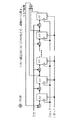
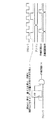
図2は、本発明の実施形態によるセキュリティ装置6のブロック図であり、図3は、図2に示すセキュリティ装置6の内部構成を図2、4、6、11、12を用いた一例を示した図であり、演算処理部19は演算処理内容によって変わる。例えば、図13に示すような秘匿データのMAC比較をするのであれば、演算処理部19は図13のような構成となる。図13については後に説明する。図2および図3に示すように、セキュリティ装置6は暗号回路9の他に、セキュリティ装置6にアクセスする際に使用される信号であるアクセス信号を圧縮(コード化、符号化)し、圧縮結果を出力する圧縮回路15(圧縮手段)と、圧縮回路15から出力された圧縮結果と、予め求められたアクセス信号の圧縮結果の期待値とを比較する比較回路16(比較手段)とを備えている。ここで、アクセス信号とは、CPU2からのアドレスや書き込み要求、読み出し要求、セキュリティ装置6の外部の状態、データ入力、暗号回路9の演算結果など、セキュリティ装置6に対して何らかの影響を与えるものである。
FIG. 2 is a block diagram of the
図4は、圧縮回路15の構成の一例を示した図である。セキュリティ装置6に入力されたアクセス信号は圧縮回路15にて圧縮される。本実施形態による圧縮回路15は、排他的論理和(EXOR)と線形フィードバックシフトレジスタ(Linear Feedback Shift Register:LFSR)とを組み合わせて構成されている。ハッシュ関数など逆計算ができない回路、あるいは入力値の一部が固定値であり外部から自由な設定ができない回路によって圧縮回路15を構成することが望ましい。圧縮する理由としては、圧縮回路15にアクセス信号の履歴を取り扱い易いビット数(例えば、AES(Advanced Encryption Standard)を搭載の場合は128bit、DES(Data Encryption Standard)を搭載の場合は64bit)にするためである。圧縮結果は、アクセス信号の履歴を記憶したデータとなる。図5に示す圧縮回路15の動作が示すように、圧縮回路15にアクセス信号を取り込むタイミングは、圧縮回路15への動作要求の度にアクセス信号を取り込んでいる。
FIG. 4 is a diagram showing an example of the configuration of the
図6は、比較回路16の構成を示した図である。比較回路16は、セキュリティ装置6からデータを出力するときに用いられる。図7に示すように、セキュリティ装置6から演算結果や内部のステータスの情報などを出力したい場合には、比較要求信号(比較イネーブル信号)をCPU2に送信し、出力許可信号を”H”にすることによってセキュリティ装置6からのデータ出力等が有効となる。
FIG. 6 is a diagram showing the configuration of the
第三者からの不正なアクセスによるデータ出力の防止方法について説明する。 A method for preventing data output due to unauthorized access from a third party will be described.
電源の投入後、セキュリティ装置6に入力されたアクセス信号は、圧縮回路15にて逐次圧縮(コード化)されて比較回路16に出力される。圧縮回路15から出力される圧縮結果は、入力されるアクセス信号毎に変化する。比較回路16には、圧縮結果の他に、予め求められた圧縮結果の期待値が入力される。期待値は予めプログラムに記述されており、プログラムは不揮発メモリ3に保存されている。また、期待値はアクセス信号とともにセキュリティ装置6に入力される。ドライバ作成者などセキュリティ装置6へのアクセスを許可された者は、圧縮回路15における圧縮方法(入力データ値やレジスタの制御手順等)を理解しているため、セキュリティ装置に対してアクセスするためのプログラムを作成する際に、圧縮回路15から出力される圧縮結果を予め計算して期待値としてプログラムに反映させることができる。
After the power is turned on, the access signal input to the
比較回路16では、入力された圧縮結果と期待値とを比較し、比較結果が一致していれば出力許可信号が”H”となってCPU2などへの出力が許可される。一方、プログラムの変更などの不正行為があれば圧縮回路15から出力される圧縮結果が期待値と異なるため、暗号回路9にて復号されたデータは出力されない。比較回路16から出力される出力許可信号とセキュリティ装置6内のステータスとに基づいて、ステータス信号を生成することができる。ステータス信号は、データ処理装置1内の何らかの重要機能から出力されるデータ出力を制御することができる。また、図3に示す重要機能とは、あるブロックから出力されるもので、CPU2を介さずに制御したい信号を想定している。
The
このように、上記の構成によって不正な改ざん行為を検出し、改ざんされたデータを出力しないようにデータの送信経路を遮断することが可能である。なお、圧縮回路15および比較回路16は、圧縮回路15および比較回路16における機能をハードウェア的に有するのがセキュリティ強度を高めるとの観点からは望ましいが、セキュリティ強度として許容できるのであればソフトウェア的に有してもよい。
As described above, it is possible to detect an unauthorized tampering action with the above configuration and to block the data transmission path so as not to output the tampered data. Note that the
セキュリティ装置6を制御するプログラムは、例えば不揮発メモリ3に保存されており、CPU2はプログラムに応じてセキュリティ装置6にアクセスする。このとき、CPU2および不揮発メモリ3はセキュリティ保護領域外であるため、悪意の第三者によって不揮発メモリ3に保存されているプログラムまたはCPU2の状態を改ざんされる恐れがある。ここで、CPU2の状態とは、デバッガを接続することによってプログラムカウンタの改ざん、レジスタの書き換え、CPUステータスフラグの書き換えなどをいう。プログラムが改ざんされるとセキュリティ装置6へのアクセス信号に何らかの変化が生じるため、比較回路16での比較結果によって改ざんを検出することが可能である。CPU2は検出された改ざん結果に応じて、改ざんを示すエラーを発生した後にデータ処理装置1の各機能を停止するなどの処置をとることができるため、データ処理装置1の使用者に対して不正な処理が発生したことを示すことができる。また、不正な処理が検出されると、データの復号に必要な処理が停止するため、MPEGデコーダ7に送信されるデータはでたらめな値となる。従って、出力I/F回路8から出力バス14を介してCRT(Cathode Ray Tube)といった表示装置などの出力装置にデータを出力したとしても、データを不正に再現することができない。このように、改ざんを示すエラーフラグを出力装置などの外部に通知することによって、不正行為に対する防衛処理を行なうことができる。すなわち、比較回路16による比較の結果、圧縮結果と期待値とが異なる場合は、暗号回路9にて復号された信号を出力せず、あるいは当該比較の結果を通知する。
A program for controlling the
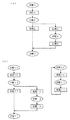
暗号に係わる演算は、例えば演算結果が正か負かなどの計算結果を元に複数の演算を組み合わせて実現することが多い。演算における条件分岐の判定はCPU2が行う。図8は、プログラムの条件分岐の判定の一例を示すフローチャートである。図8に示すように、演算処理には複数の演算および条件分岐が存在する。暗号回路9から発生する符合などの演算結果を条件として演算を行う場合において、CPU2は暗号回路9から読み出した演算結果に基づいて行うべき演算を選択して実施する。しかし、このときに、デバッガなどを用いて悪意の第三者によって改ざんされる恐れがある。例えば、図8において、条件1、2、3がそれぞれ(0、1、1)と判定されると、処理は演算1、演算3、演算6の順に行われるが、改ざんによって条件1が(1)に書き換えられると、処理は演算1、演算2、演算4の順に行われてしまう。
The computation related to encryption is often realized by combining a plurality of computations based on the computation result such as whether the computation result is positive or negative. The
本実施形態では、演算処理を暗号回路9で行い、演算結果である条件分岐や後述する図9に示す補正値などの情報を必要に応じて圧縮回路15に入力する(取り込む)ことによって、圧縮回路15から出力された圧縮結果と期待値とを比較回路16にて比較している。従って、期待値と圧縮結果との比較によって不正処理を検出できるため、演算結果と異なる条件判断を不正操作によりCPU2に実行させたとしても、圧縮結果を元に不正行為が検出される(本来は0である判定が1に変更したことを検出する)ため、セキュリティ装置6を停止させるなど改ざんされたデータの出力を防止することが可能となる。また、演算終了などの暗号回路9の状態を示す情報を圧縮回路15に入力することによって、演算終了後に次の処理に進めること強制することができる。これは、演算結果を次の演算に使用する場合に、演算終了を待たずに処理を進めることができてしまうと演算の改ざんと同様の効果が得られてしまうことを防止するためである。ただし、このような運用に該当しない場合には、演算結果を圧縮結果に反映させなくてもよい。
In the present embodiment, calculation processing is performed by the
プログラムが分岐を伴う処理の場合において、プログラムが分岐した後に合流する際に圧縮回路15から出力される圧縮結果が異なるため、圧縮結果を補正する必要がある。図9は、プログラムの処理が分岐後に合流する場合における圧縮結果の補正の一例について示した図である。本実施形態では、例えば、圧縮結果を32bitとして圧縮回路15の初期値を(83649bd6)16とする。制御命令1を実行することによって、圧縮結果が(83649bd6)16から(936f036a)16に変化している。制御命令1の後、条件分岐命令にて条件(a)または条件(b)が実行される。条件(a)の場合では、制御命令2が実行されて圧縮結果が(f7db2511)16に変化している。条件(b)の場合では、制御命令3が実行されて圧縮結果が(16385baf)16に変化して条件分岐処理を終了している。条件(a)では、制御命令2の実行後に制御命令4の実行時に、制御命令4による実行結果が条件(b)の分岐処理の結果である(16385baf)16となるように、制御命令2の実行後の圧縮結果である(f7db2511)16に対して補正値を入力する。圧縮回路15の演算方法が分かれば補正値を求めることができる。
In the case where the program is a process involving branching, the compression result output from the
以上の操作を行うことによって、プログラムにおいて条件分岐が発生した場合であっても、合流後に圧縮結果に不整合が生じないように圧縮結果を調整しながら処理を進めることが可能となる。すなわち、暗号化された信号はセキュリティ装置6を制御するプログラムを含み、プログラムが条件分岐を伴う場合において、条件分岐後に合流したときに圧縮結果が同一となるように圧縮回路15に補正値を入力する。従って、プログラムを書き換えるなどのセキュリティ装置6に対するアクセスの改ざんを検出することができる。このような改ざんを検出することによって、CPU2へのデータ出力の停止や特定の機能を停止することができるため、不正アクセスによる秘匿データの取得を防止することが可能となる。なお、改ざんの検出によってデータ出力を停止することの他に、セキュリティ装置6の応答を停止するなどの他の処理であってもよい。また、本実施形態では、暗号回路9による演算結果を圧縮回路15に入力することによって、不正な操作で条件分岐の判断結果が改ざんされた場合であっても検出することが可能である。
By performing the above operations, even if a conditional branch occurs in the program, it is possible to proceed with processing while adjusting the compression result so that no inconsistency occurs in the compression result after merging. In other words, the encrypted signal includes a program for controlling the
期待値や補正値が組み込まれたプログラムは、セキュリティ保護領域外に保存されている。例えば、不揮発メモリ3は通常CPU2のメモリ空間にマッピングされているため、デバッガを接続することによって容易に内容を読み出すことができる。プログラムに組み込まれた期待値および補正値は、予め暗号化されて不揮発メモリ3に保存されているが、圧縮回路15の計算方法を推測するデータとなるため安全に運用する手段があるほうが望ましい。
Programs that incorporate expected values and correction values are stored outside the security protection area. For example, since the
図10は、本発明の実施形態によるセキュリティ装置6のブロック図である。図10に示すセキュリティ装置6では、暗号化された信号は期待値および補正値を含み、暗号化された期待値および暗号化された補正値は暗号回路9にて復号される。このようにすることによって、期待値や補正値を元に圧縮回路15が解析されることを困難にしている。図10に示すように、暗号化された期待値は、データ入力からセキュリティ装置6に入力されて暗号回路9にて復号された後、比較回路16に入力される。一方、暗号化された補正値は、データ入力からセキュリティ装置6に入力されて暗号回路9にて復号された後、圧縮回路15に入力される。
FIG. 10 is a block diagram of the
このような構成にすることによって、不揮発メモリ3に保存される期待値や補正値など、セキュリティ保護領域外に保存されているデータから圧縮回路15の仕様が特定されることを困難にすることが可能である。また、上記の処理について、コンテンツの復号に用いられる暗号回路9を共用できるため、回路規模を抑えることができ、コンテンツの復号と同程度の解読の困難さを得ることができる。なお、本実施形態では暗号回路9を用いたが、暗号回路9とは別の演算回路を用いて上記の処理を行なってもよい。
With such a configuration, it is difficult to specify the specifications of the
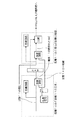
セキュリティ装置6の内部には、初期化が必要な回路が存在する。例えば、圧縮回路15では、初期化を悪意の第三者が任意のタイミングで行えないようにし、初期値も推測できないようにすることが望ましい。図11は、圧縮回路15の初期化の方法を示す図である。
Inside the
まず始めに、CPU2はセキュリティ装置6を動作させるために、初期化に必要なシステム鍵の生成のためのアクセスを行う。ここで、システム鍵とは、不揮発メモリ3などに保存される電源投入ごとに変化しない固定値の秘匿データを暗号化や復号するための元となる鍵のことであり、システムごとに異なる値となる。システム鍵は、セキュリティ装置6の外部への読み出しが不可能な固定情報である固有情報18と、不揮発メモリ3に保存されている暗号化固有情報10とを、暗号回路9内の演算回路を用いて生成される。システム鍵が生成されると、システム鍵の生成要求(=1)を受けてセキュリティモード信号が”H”になる。セキュリティモード信号は、システム鍵が生成されるまでは0であり、システム鍵が演算回路を通して初期値として圧縮回路15に入力される。システム鍵の生成後は、セキュリティモード信号が1となるため、圧縮回路15へは通常経路の入力しか行われなくなる。すなわち、システム鍵を暗号回路9内の演算回路に通して生成された値を圧縮回路15の初期値として利用している。そして、システム鍵の生成要求がCPU2からあると、圧縮回路15の初期化を一度だけ行う。なお、本実施形態では、システム鍵を撹拌するための演算回路は、システム鍵の解析を困難にするために設けているが、システム鍵によって圧縮回路15を初期化してもよい。
First, in order to operate the
上記の例では、セキュリティモード信号を非活性にできない回路構成となっているが、一度活性化されたセキュリティモード信号を非活性にする機能を設ける場合には、非活性にするとともに活性時に使用するセキュリティに関わるデータ記憶領域をクリアする機能を設けるなどしてデータの不正利用を防止すればよい。また、本実施形態では、セキュリティモード信号を圧縮回路15の入力前にセレクタを設けてセレクト信号として用いたが、セキュリティモード信号を図2に示すデコーダに入力してセキュリティモード時の圧縮回路15への初期化のアクセスを無効にしてもよい。
In the above example, the circuit configuration is such that the security mode signal cannot be deactivated. However, when a function to deactivate the security mode signal once activated is provided, it is deactivated and used when activated. It is only necessary to prevent unauthorized use of data by providing a function for clearing a data storage area related to security. In this embodiment, the security mode signal is provided as a select signal by providing a selector before the
以上のように、圧縮回路15の初期化をシステム鍵の生成時にのみ行うことによって、圧縮回路15に対する不正利用を防止し、圧縮方法についての解析を困難にすることが可能である。
As described above, by performing initialization of the
装置の複製による不正なコンテンツの復号を防止するために、コンテンツを復号するための鍵や、鍵を生成するために必要な情報は装置毎に異なる。これらの情報は不揮発メモリ3に保存されているが、不揮発メモリ3はセキュリティ保護領域外であるため、悪意の第三者によって情報が読み出されて別の装置の不揮発メモリ3にコピー(複製)される恐れがある。そのため、不揮発メモリ3内の情報が複製されることを防止する必要がある。図12は、不揮発メモリ3の複製防止を示す図である。図12に示すように、装置固有情報17はデータ処理装置1内部の不揮発メモリ3の固有情報であり、メモリごとに値が異なり、かつ一度書き込んだら変化しないものなら何でもよい。例えば、ヒューズROMや電子線による配線切断などを用いてもよい。この装置固有情報17をシステム鍵の生成に含めるとそのメモリのみにしか利用できなくなるため、セキュリティ保護領域外の不揮発メモリ3内のデータが複製された場合であっても、他の装置で暗号化固有情報が流用されることを防止することができる。
In order to prevent unauthorized content decryption due to device duplication, the key for decrypting the content and the information necessary for generating the key differ from device to device. These pieces of information are stored in the
コンテンツを復号するための鍵や、鍵を生成するために必要な情報は、セキュリティ保護領域外である不揮発メモリ3内に暗号化固有情報10として保存されている。暗号化固有情報10は秘匿データであるため、暗号化だけでなく署名(Media Access Control:MAC)を付加する必要がある。MAC検証の判定は、CPU2にて判定を行うと判定を改ざんされる恐れがあるため、CPU2で行うだけでは不十分である。
A key for decrypting the content and information necessary for generating the key are stored as the encryption
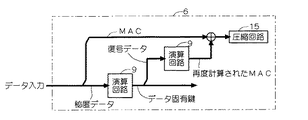
図13は、秘匿データのMAC検証の一例について示した図である。図13に示すように、不揮発メモリ3からセキュリティ装置6に暗号化固有情報10などの秘匿データが入力されると、秘匿データは暗号回路9内の演算回路によって復号(秘匿データのMAC値に復号)された後に、再び暗号回路9内の演算回路によってMACが生成される。その後、データ入力から入力されたMACと、前述した復号結果を元に再生成されたMACとの比較結果とを圧縮回路15に入力する。具体的な例としては、秘匿データを暗号化してMACを付加してセキュリティ装置6の外部に一時的に出し(例えばRAM5に一時的に保存し)、再度秘匿データを利用するときに上記の構成によって復号してMACを検証する。そして、検証結果を圧縮回路15の圧縮結果に反映させることによって、データが正しくなければ改ざんと判断される。
FIG. 13 is a diagram illustrating an example of MAC verification of confidential data. As shown in FIG. 13, when secret data such as encrypted
このように、MAC検証の判定をCPU2ではなく圧縮回路15で行っているため、比較して得られた秘匿データのMAC検証結果を圧縮回路15の圧縮結果に反映させることができ、秘匿データに対する不正な改ざんをセキュリティ装置6にて防止することができる。
Thus, since the determination of MAC verification is performed not by the
コンテンツの保護には、共通鍵暗号や公開鍵暗号など複数の暗号回路9を利用するため、暗号化固有情報10も複数存在することが考えられる。このような秘匿データが、例えばシステム鍵などの単一の鍵によって暗号化されると、どの秘匿データもシステム鍵で復号できるため不正に秘匿データを入れ換えることが可能となってしまう。つまり、管理する秘匿データが複数ある場合において、同じ鍵で秘匿データを管理するとデータが入れ換えられてとしても、入れ換えられたことを検出することができない。そのため、不正な秘匿データの入れ換えを防止する必要がある。
In order to protect the content, a plurality of
図14は、種別による秘匿データの入れ換え防止の一例を示した図である。本実施形態では、個々の秘匿データに対する固有の情報として種別を用いる。種別は、秘匿データの種類を示すデータ(種別データ)であって固有値であるため不揮発メモリ3に保存される。種別の値は、個々のデータに対して任意の値をプログラムの作成者が決定すればよい。図14に示すように、CPU2はデータ入力から種別の書き込みアクセスを行う。セキュリティ装置6に書き込まれた種別は、システム鍵とともに暗号回路9の演算回路で演算されてデータ固有鍵が生成される。このように、システム鍵をそのまま使用せずに秘匿データ毎に種別を用意し、種別を鍵の情報としてデータ固有鍵に含められている。生成されたデータ固有鍵は、秘匿データ毎に違う値の種別を元に演算回路で計算されているため秘匿データ固有のものである。入力された秘匿データは、データ固有鍵とともに暗号回路9の演算回路で演算されて復号される。復号データのMAC検証が必要であれば、図13に示す処理を引き続き行なう。また、種別は圧縮回路15にも入力されて圧縮結果に反映させ、データの入れ換えなどの改ざんを検出する。つまり、誤った種別であれば鍵が変わるため、データが入れ換えられたことを検出することが可能である。
FIG. 14 is a diagram illustrating an example of prevention of confidential data replacement according to type. In this embodiment, a type is used as unique information for each secret data. The type is data (type data) indicating the type of confidential data and is a unique value and is stored in the
このように、秘匿データを復号する場合において、秘匿データの種類を示す種別データを用いて復号し、種別データを圧縮回路15に入力するといった処理を行なうことによって、秘匿データが入れ換えられた場合は種別が合わないため、データ固有鍵が正しく生成されずデータの復号ができない。また、種別を書き換えるということは、プログラムを改ざんしたことにもなるため、プログラムの改ざんを検出することも可能である。さらに、図13に示すMAC検証を組み合わせることによって、秘匿データを入れ換えるとMAC検証の結果が合わなくなるため、二重に検証することが可能である。
As described above, when the confidential data is decrypted, the confidential data is replaced by performing processing such as decoding using the type data indicating the type of the confidential data and inputting the type data to the
公開鍵暗号などで使用するパラメータ(素数や楕円関数の固定値など)が複数存在する場合において、同一機能で使用される秘匿データに対して別の種別を付加することは、プログラムを共通化させるのに効率が悪い。例えば、楕円暗号によるMAC検証のドメインパラメータが複数ある場合は、MAC検証の処理手順を共通化する方が、プログラムサイズや開発の点からも効率が良くなる。このように、演算の種類は同じだが使用するパラメータが異なる演算において、各演算に使用するパラメータを強制しなければならない。本実施形態では、各パラメータにグループの管理のためのグループ管理コードを付加し、グループ番号を復号時の鍵に反映させている。グループ管理コードは、同一目的の秘匿データ群を区別するための固定値のデータであり、不揮発メモリ3に保存される。グループ管理コードの値は、プログラムの作成者が任意に決定する。
When there are multiple parameters (such as prime numbers and fixed values of elliptic functions) used in public key cryptography, adding another type to the secret data used for the same function makes the program common However, it is inefficient. For example, when there are a plurality of domain parameters for MAC verification using elliptic encryption, it is more efficient in terms of program size and development to share the MAC verification processing procedure. In this way, in an operation that uses the same type of operation but uses different parameters, the parameter to be used for each operation must be forced. In this embodiment, a group management code for group management is added to each parameter, and the group number is reflected in the key at the time of decryption. The group management code is fixed value data for distinguishing secret data groups having the same purpose, and is stored in the
図15は、グループ管理コードによる秘匿データの入れ換え防止の一例を示した図である。図15に示すように、不揮発メモリ3から入力されたグループ管理コードと、システム鍵とを暗号回路9内の演算回路で演算してグループ固有鍵を生成する。生成されたグループ固有鍵と種別とを演算回路で演算してグループ内データ固有鍵を生成し、生成されたグループ内データ固有鍵を用いて演算回路にて秘匿データを復号する。このとき、グループ管理コードおよび種別は、圧縮回路15に入力される。
FIG. 15 is a diagram illustrating an example of prevention of confidential data replacement by the group management code. As shown in FIG. 15, the group management code input from the
グループで管理される秘匿データ群に付加される種別は、他のグループの同一機能の秘匿データと共通の値でよい。図16は、グループ管理コードについて説明した図である。図16(a)では、グループ1およびグループ2が存在し、データAとデータA’、データBとデータB’、データCとデータC’とがそれぞれ同じ機能であり、各機能について種別a、b、cを付加している。図16(a)では、データを復号する鍵にグループ管理コードが含まれず各種別に対するグループに依存しない鍵x、y、zが生成されているため、グループ1およびグループ2の同一機能のデータを復号することができる。すなわち、グループの途中のデータが入れ換えられても検出することができない。しかし、図16(b)に示すように、データを復号する鍵情報にグループ管理コードを含めることによって、同一機能を有する種別であっても鍵がグループ単位で異なるため、グループ間でデータが入れ換えられると正しく復号されない。
The type added to the secret data group managed by the group may be a value common to the secret data of the same function of other groups. FIG. 16 is a diagram illustrating the group management code. In FIG. 16A,
このように、秘匿データを復号する場合において、同一目的の秘匿データ群を区別するグループ管理コードを用いて復号し、グループ管理コードを圧縮回路15に入力することによって、データをグループ間で不正に入れ換えられたとしても、その改ざんを検出することができる。
As described above, when the secret data is decrypted, the group management code that distinguishes the secret data group of the same purpose is decrypted and the group management code is input to the
セキュリティ装置6内に保存できるデータ量には限りがあるため、演算の途中で生成される秘匿データの全てをセキュリティ装置6内に保存したまま処理を続けることが困難になることがある。このような場合には、一般的にはセキュリティ装置6の外部に設けられたRAM5に秘匿データを一時的に退避すればよいが、RAM5はセキュリティ保護領域外であるため一時的に退避した秘匿データを保護する必要がある。
Since the amount of data that can be stored in the
図17は、データの一時的な退避方法を示す図である。図17に示すように、まず始めに、暗号回路9内の乱数生成機能によって乱数を生成する。生成された乱数とセキュリティ装置6に入力された秘匿データに対応した種別とを暗号回路内9内の演算回路で演算することによってデータ固有一時鍵を生成する。データ固有一時鍵を用いて暗号回路9内の演算回路にて秘匿データを暗号化し、暗号化した秘匿データをセキュリティ装置6の外部であるRAM5に出力する。このとき、秘匿データの種別は圧縮回路15に入力される。複数の暗号化された秘匿データを出力する場合は、どのデータが出力されたのかを種別で判断する。その種別は圧縮回路15で履歴として管理されている。鍵を生成に制御できない乱数を秘匿データの暗号化に用いることによって、別のタイミングで一時的に保存したデータをデータの種別が同じであっても入力することができなくなる。暗号化した秘匿データを復号するまでは、生成したデータ固有一時鍵を何らかの形でセキュリティ装置6内に保持しておく必要があり、使用後は破棄する。
FIG. 17 is a diagram illustrating a method for temporarily saving data. As shown in FIG. 17, first, a random number is generated by a random number generation function in the
このように、セキュリティ装置6内部のデータを一時的に記憶するRAM5(記憶手段)をさらに備え、秘匿データをRAM5に記憶させる場合において、種別データと乱数とからデータ固有一時鍵を生成し、データ固有一時鍵を用いて秘匿データを暗号化してRAM5に記憶させることによって、データ固有一時鍵の生成や破棄の手順のプログラムを変更されるようなデータの書き換えが行われても、プログラムの改ざんが行われたとして検出される。
As described above, when the RAM 5 (storage means) for temporarily storing the data inside the
複数の状態を有するプログラム(マルチタスク)を実行する場合について示す。セキュリティ装置6では、圧縮回路15で演算されて出力される圧縮結果に基づいてデータの改ざんの有無を検出している。圧縮結果は処理に応じて変化することから、プログラムの遷移状態と捉えることもできる。
A case where a program (multitask) having a plurality of states is executed will be described. The
図18は、セキュリティ装置6における処理の状態の一例を示す図である。図18(a)は、任意のタイミングで保持する状態が一つしかない場合を示している。状態が一つの場合において、圧縮結果の値は状態1から状態4のそれぞれに対して一意に決まる。一方、図18(b)に示すように、複数の状態を同時に管理する必要がある場合は、圧縮結果の値が一意にならない。例えば、状態10および状態20の状態から処理を開始しても、状態1xと状態2xとの処理には関連がないため、圧縮結果の値は一意にならない。図18(b)に示す状態遷移では、処理10と処理20との処理の順序はどちらからでもよいが圧縮結果は異なる。
FIG. 18 is a diagram illustrating an example of a processing state in the
図19は、セキュリティ装置6における複数の状態を管理する方法を示す図である。まず始めに、暗号回路9の乱数生成機能を用いて各状態遷移に対応する一時鍵を生成する。この一時鍵は、同時に管理する状態遷移の数だけ必要であり、例えば図19では2つ(状態1系、状態2系)必要である。次に、状態10、状態11、状態21などの各状態を表す固有の値として種別を準備する。暗号回路9の乱数生成機能にて生成された状態遷移の一時鍵と入力されたデータの状態の種別とを暗号回路9内の演算回路で演算し、現在の状態を示すデータとして各状態遷移毎に生成する。生成した現在の状態を示すデータは、RAM5に保存される。保存されたデータは、プログラムが現在どの状態まで進行しているかの目印となる。このような処理によって、RAM5に現在の状態を示すデータを保存した状態での圧縮結果は一意に決まり、これを圧縮結果の基準値とする。すなわち、関連のない2つの状態を管理するために、圧縮回路15の値をある基準値にしておくことで、基準値から各処理(処理10、11、12、13、20、21)を行なうようにしている。処理10や処理11などの各処理では、実行されている処理が正しいかを確認するために現在の状態を確認した後に処理を実行する。この確認は、処理に対応した状態の種別とRAM5に予め保存されている現在の状態を示すデータと比較することによって行われる。なお、現在の状態を示すデータをRAM5に保存する際に、改ざんを防止するためにMACの生成も併せて行う必要があるが、説明の簡略化のためにデータに対するMAC処理については省略する。
FIG. 19 is a diagram illustrating a method for managing a plurality of states in the
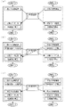
図20は、状態データの生成と状態の確認の方法を示す図である。図20に示すように、処理11では、処理10が完了した状態で実行されるため、プログラム内に処理10の種別を用いてRAM5に保存されている値を検証する。比較結果やMAC検証結果などは、全て圧縮回路15に反映させる。例えば、処理10において、現在の状態確認に問題がなければ処理10’を行う。処理10’の完了後に、次の状態(例えば状態11)にて使用する状態遷移の一時鍵を再生成し、次の状態(状態11)を示す種別を用いて現在の状態を示すデータ(状態11を示すデータ)を生成してRAM5に保存する。処理10の最後には、圧縮結果が処理によって変化しているため、基準値に戻すように補正値を入力してから処理10を終了する。このように、実行される処理が正しいかどうかはRAM5に保存した現在の状態を示すデータを用いて確認し、処理内容のデータの改ざんは圧縮結果を用いて検出している。従って、複数の状態遷移を有する処理を安全に実行することが可能となる。
FIG. 20 is a diagram illustrating a method of generating state data and checking a state. As shown in FIG. 20, in the
図21は、複数の状態間における処理の共通化を示す図である。MAC検証など特定の手順を共通化することによって、プログラムのメンテナンスが容易になったり、プログラムサイズが小さくなったりするという利点がある。図21(a)に示すように、2つの状態の処理の一部を共通化した(共通処理A)場合において、共通処理A内にて圧縮回路15による圧縮結果を用いた判定処理を行う際に、それぞれの状態で異なる圧縮結果が共通処理A内の圧縮回路15に入力されるため処理が正しく行なわれない。そこで、図21(b)に示すように、共通処理Aに入るときに共通の圧縮結果になるように各状態の処理にて補正を行う(圧縮回路15の値が基準値となる)。このようにすると、共通処理Aを実行することはできるが、共通処理A後の圧縮結果が両方の状態遷移間で共通になってしまい、例えば処理20が途中で処理10に遷移してしまう恐れがある。このような問題をなくすために、図21(c)では、共通処理Aの後に現在の状態確認を再度行うことによって、処理10と処理20とのどちらの状態遷移から実行されたのかを判定することができる。従って、MAC検証など特定の手順の共通化を行いながら、複数の状態遷移を管理することができる。
FIG. 21 is a diagram showing the sharing of processing among a plurality of states. By sharing a specific procedure such as MAC verification, there is an advantage that the maintenance of the program is facilitated and the program size is reduced. As shown in FIG. 21A, when a part of the processing in the two states is shared (common processing A), the determination processing using the compression result by the
不揮発メモリ3に保存されている暗号化固有情報10などの秘匿情報を用いる場合には、MAC検証処理を行なって改ざんの有無を確認している。このような改ざんの確認処理が共通処理に複数含まれている場合には、図13に示すようなMAC検証結果を直接圧縮回路15に反映させると、共通処理後の圧縮結果は2のMAC検証回数乗のバリエーションが生じてしまう。すなわち、プログラムの共通化に伴って、共通化された箇所のPASS、FAILを圧縮回路15に反映すると複数の圧縮結果が必要となり、プログラムの作成が複雑になってプログラムコードが増加する。従って、このような問題の対策が必要となる。
When using confidential information such as the encrypted
図22は、共通処理におけるエラー判定方法を示す図である。共通処理の中でエラー判定をする箇所が複数ある場合には、2値(改ざん検出の有無)である署名(MAC)検証結果をレジスタ(FlipFlop:FF)にて保持する。ここで、改ざんが検出された場合を1とする。FFの値は、一度セットされると圧縮回路15に反映するまで初期化(0)されない。FFの出力は、一度でもエラーが検出されると1になるため、共通処理の終了時に圧縮回路15に反映させることにより状態を2値にすることが可能となる。このように、検証結果を検証のたびに圧縮回路15に反映させると圧縮回路15での処理が煩雑化してしまうが、エラー判定結果を圧縮回路15とは異なるFFに保持しておき、共通処理の終了後に判定結果を圧縮回路15に反映させることによって容易に手順の共通化を行うことができる。
FIG. 22 is a diagram illustrating an error determination method in common processing. When there are a plurality of locations where error determination is performed in the common processing, a signature (MAC) verification result that is binary (whether or not falsification is detected) is held in a register (FlipFlop: FF). Here, the case where tampering is detected is 1. Once set, the FF value is not initialized (0) until it is reflected in the
図23は、複数の状態を管理する方法を示す図である。複数の状態遷移が存在する場合では、状態の数だけの一時鍵の保存が必要となって管理が煩雑となる。図23に示すように、状態遷移の一時鍵の全てに共通の鍵を暗号回路9の乱数生成機能によって生成する。一方、実行する状態遷移を示す状態遷移番号を入力する手段をレジスタなどで準備する。状態遷移番号は、同時に管理する状態遷移の数だけ必要となる。状態遷移共通の一時鍵と状態遷移番号とを暗号回路9の演算回路にて演算し、実行する状態遷移の一時鍵を生成する。
FIG. 23 is a diagram illustrating a method for managing a plurality of states. When there are a plurality of state transitions, it is necessary to store as many temporary keys as the number of states, and management becomes complicated. As shown in FIG. 23, a key common to all temporary keys for state transition is generated by the random number generation function of the
このように、暗号化された信号はセキュリティ装置6を制御するプログラムを含み、プログラムで複数の状態遷移が存在する場合において、全ての状態遷移に共通する一時鍵を乱数によって生成した一時鍵と、各状態遷移に割り当てられた番号とから各状態遷移の一時鍵を生成することによって、鍵を管理するためのレジスタの数を削減することができる。
In this way, the encrypted signal includes a program for controlling the
なお、本発明の実施形態は、DVDやBlue−ray、HD−DVDなどの映像データを扱う民生機器、ハードディスクなどデータを保存するためのストレージ製品、VPN(Virtual Private Network)などのネットワーク関連機器、データ処理に秘密性や正当性などの安全性が要求されるマイコン、ASIC(Application Specific Integrated Circuit)などに利用可能である。 The embodiments of the present invention include consumer devices that handle video data such as DVDs, Blue-rays, and HD-DVDs, storage products that store data such as hard disks, network-related devices such as VPNs (Virtual Private Networks), The present invention can be used for microcomputers, ASIC (Application Specific Integrated Circuit), and the like that require security such as confidentiality and correctness for data processing.
1 データ処理装置、2 CPU、3 不揮発メモリ、4 入力I/F回路、5 RAM、6 セキュリティ装置、7 MPEGデコーダ、8 出力I/F回路、9 暗号回路、10 暗号化固有情報、11 CPUバス、12 入力バス、13 内部バス、14 出力バス、15 圧縮回路、16 比較回路、17 装置固有情報、18 固有情報、19 演算処理部。 1 data processing device, 2 CPU, 3 nonvolatile memory, 4 input I / F circuit, 5 RAM, 6 security device, 7 MPEG decoder, 8 output I / F circuit, 9 encryption circuit, 10 encryption specific information, 11 CPU bus , 12 input bus, 13 internal bus, 14 output bus, 15 compression circuit, 16 comparison circuit, 17 device unique information, 18 unique information, 19 arithmetic processing unit.
Claims (11)
前記セキュリティ装置は、
前記セキュリティ装置にアクセスする際に使用される信号であるアクセス信号を圧縮し、圧縮結果を出力する圧縮手段と、
前記圧縮手段から出力された前記圧縮結果と、予め求められた前記アクセス信号の圧縮結果の期待値とを比較する比較手段と、
を備えることを特徴とする、データ処理装置。 Comprising a security device having an encryption means for decrypting an encrypted signal including confidential data;
The security device comprises:
Compression means for compressing an access signal, which is a signal used when accessing the security device, and outputting a compression result;
Comparison means for comparing the compression result output from the compression means with an expected value of the compression result of the access signal obtained in advance;
A data processing apparatus comprising:
前記秘匿データを前記記憶手段に記憶させる場合において、前記種別データと乱数とからデータ固有一時鍵を生成し、前記データ固有一時鍵を用いて前記秘匿データを暗号化して前記記憶手段に記憶させることを特徴とする、請求項7または請求項8に記載のデータ処理装置。 Further comprising storage means for temporarily storing data inside the security device;
When storing the secret data in the storage means, a data unique temporary key is generated from the type data and a random number, and the secret data is encrypted using the data unique temporary key and stored in the storage means. The data processing device according to claim 7 or 8, characterized by the above.
前記プログラムで複数の状態遷移が存在する場合において、全ての状態遷移に共通する一時鍵を乱数によって生成した一時鍵と、各状態遷移に割り当てられた番号とから各状態遷移の一時鍵を生成することを特徴とする、請求項1ないし請求項9のいずれかに記載のデータ処理装置。 The encrypted signal includes a program for controlling the security device;
When a plurality of state transitions exist in the program, a temporary key for each state transition is generated from a temporary key generated by a random number and a number assigned to each state transition. The data processing device according to claim 1, wherein the data processing device is a data processing device.
Priority Applications (5)
| Application Number | Priority Date | Filing Date | Title |
|---|---|---|---|
| JP2008102392A JP5060372B2 (en) | 2008-04-10 | 2008-04-10 | Data processing device |
| US12/401,427 US8140858B2 (en) | 2008-04-10 | 2009-03-10 | Data processing apparatus |
| TW098109936A TWI518539B (en) | 2008-04-10 | 2009-03-26 | Data processing device |
| CN200910133145.8A CN101556638B (en) | 2008-04-10 | 2009-04-09 | Data processing apparatus |
| US13/310,441 US9092619B2 (en) | 2008-04-10 | 2011-12-02 | Data processing apparatus |
Applications Claiming Priority (1)
| Application Number | Priority Date | Filing Date | Title |
|---|---|---|---|
| JP2008102392A JP5060372B2 (en) | 2008-04-10 | 2008-04-10 | Data processing device |
Publications (2)
| Publication Number | Publication Date |
|---|---|
| JP2009252142A true JP2009252142A (en) | 2009-10-29 |
| JP5060372B2 JP5060372B2 (en) | 2012-10-31 |
Family
ID=41164955
Family Applications (1)
| Application Number | Title | Priority Date | Filing Date |
|---|---|---|---|
| JP2008102392A Active JP5060372B2 (en) | 2008-04-10 | 2008-04-10 | Data processing device |
Country Status (4)
| Country | Link |
|---|---|
| US (2) | US8140858B2 (en) |
| JP (1) | JP5060372B2 (en) |
| CN (1) | CN101556638B (en) |
| TW (1) | TWI518539B (en) |
Families Citing this family (5)
| Publication number | Priority date | Publication date | Assignee | Title |
|---|---|---|---|---|
| JP2011008701A (en) * | 2009-06-29 | 2011-01-13 | Sony Corp | Information processing server, information processing apparatus, and information processing method |
| US9459955B2 (en) * | 2012-05-24 | 2016-10-04 | Sandisk Technologies Llc | System and method to scramble data based on a scramble key |
| JP6280794B2 (en) * | 2013-04-12 | 2018-02-14 | 株式会社半導体エネルギー研究所 | Semiconductor device and driving method thereof |
| JP6986678B2 (en) * | 2017-07-10 | 2021-12-22 | パナソニックIpマネジメント株式会社 | Video signal processing device and video signal transmission system |
| KR102490191B1 (en) * | 2018-03-05 | 2023-01-18 | 삼성전자주식회사 | Data storage device and method of operating the same |
Citations (8)
| Publication number | Priority date | Publication date | Assignee | Title |
|---|---|---|---|---|
| JPH09282156A (en) * | 1996-04-17 | 1997-10-31 | Ricoh Co Ltd | Program protection device and program protection method |
| JP2000322253A (en) * | 1999-05-14 | 2000-11-24 | Namco Ltd | Security system |
| JP2000330783A (en) * | 1999-05-20 | 2000-11-30 | Nec Corp | Software illegal copy prevention system and recording medium with software illegal copy prevention program recorded thereon |
| JP2000339153A (en) * | 1999-05-25 | 2000-12-08 | Nippon Telegr & Teleph Corp <Ntt> | Method and device for verifying program and storage medium storing program verification program |
| JP2001229018A (en) * | 2000-02-16 | 2001-08-24 | Ricoh Co Ltd | Program execution control apparatus |
| JP2003051819A (en) * | 2001-08-08 | 2003-02-21 | Toshiba Corp | Microprocessor |
| JP2005222418A (en) * | 2004-02-06 | 2005-08-18 | Nec Electronics Corp | Program falsification detection device, program falsification detection program and program falsification detection method |
| JP2005227995A (en) * | 2004-02-12 | 2005-08-25 | Sony Corp | Information processor, information processing method and computer program |
Family Cites Families (11)
| Publication number | Priority date | Publication date | Assignee | Title |
|---|---|---|---|---|
| US5812663A (en) | 1994-12-29 | 1998-09-22 | Fujitsu Limited | Data reproducing device |
| US5675645A (en) * | 1995-04-18 | 1997-10-07 | Ricoh Company, Ltd. | Method and apparatus for securing executable programs against copying |
| FR2790844B1 (en) | 1999-03-09 | 2001-05-25 | Gemplus Card Int | METHOD AND DEVICE FOR MONITORING THE PROGRESS OF A PROGRAM, PROGRAM DEVICE FOR MONITORING ITS PROGRAM |
| US7757097B2 (en) * | 1999-09-03 | 2010-07-13 | Purdue Research Foundation | Method and system for tamperproofing software |
| JP4009437B2 (en) * | 2001-05-09 | 2007-11-14 | 株式会社ルネサステクノロジ | Information processing device |
| DE10340411B4 (en) * | 2003-09-02 | 2005-10-13 | Infineon Technologies Ag | Device and method for the safe execution of a program |
| EP1538509A1 (en) * | 2003-12-04 | 2005-06-08 | Axalto S.A. | Method for securing a program execution against radiation attacks |
| JP4229330B2 (en) | 2005-01-11 | 2009-02-25 | 株式会社リコー | Cryptographic program generation device and cryptographic program generation method |
| JP2007131107A (en) | 2005-11-09 | 2007-05-31 | Nissan Motor Co Ltd | Motor-driven four-wheel drive car |
| US20080148061A1 (en) * | 2006-12-19 | 2008-06-19 | Hongxia Jin | Method for effective tamper resistance |
| JP2008287449A (en) | 2007-05-17 | 2008-11-27 | Renesas Technology Corp | Data processor |
-
2008
- 2008-04-10 JP JP2008102392A patent/JP5060372B2/en active Active
-
2009
- 2009-03-10 US US12/401,427 patent/US8140858B2/en active Active
- 2009-03-26 TW TW098109936A patent/TWI518539B/en active
- 2009-04-09 CN CN200910133145.8A patent/CN101556638B/en active Active
-
2011
- 2011-12-02 US US13/310,441 patent/US9092619B2/en active Active
Patent Citations (8)
| Publication number | Priority date | Publication date | Assignee | Title |
|---|---|---|---|---|
| JPH09282156A (en) * | 1996-04-17 | 1997-10-31 | Ricoh Co Ltd | Program protection device and program protection method |
| JP2000322253A (en) * | 1999-05-14 | 2000-11-24 | Namco Ltd | Security system |
| JP2000330783A (en) * | 1999-05-20 | 2000-11-30 | Nec Corp | Software illegal copy prevention system and recording medium with software illegal copy prevention program recorded thereon |
| JP2000339153A (en) * | 1999-05-25 | 2000-12-08 | Nippon Telegr & Teleph Corp <Ntt> | Method and device for verifying program and storage medium storing program verification program |
| JP2001229018A (en) * | 2000-02-16 | 2001-08-24 | Ricoh Co Ltd | Program execution control apparatus |
| JP2003051819A (en) * | 2001-08-08 | 2003-02-21 | Toshiba Corp | Microprocessor |
| JP2005222418A (en) * | 2004-02-06 | 2005-08-18 | Nec Electronics Corp | Program falsification detection device, program falsification detection program and program falsification detection method |
| JP2005227995A (en) * | 2004-02-12 | 2005-08-25 | Sony Corp | Information processor, information processing method and computer program |
Also Published As
| Publication number | Publication date |
|---|---|
| CN101556638B (en) | 2013-10-16 |
| TW201003455A (en) | 2010-01-16 |
| US8140858B2 (en) | 2012-03-20 |
| TWI518539B (en) | 2016-01-21 |
| US20090259856A1 (en) | 2009-10-15 |
| US9092619B2 (en) | 2015-07-28 |
| CN101556638A (en) | 2009-10-14 |
| US20120079286A1 (en) | 2012-03-29 |
| JP5060372B2 (en) | 2012-10-31 |
Similar Documents
| Publication | Publication Date | Title |
|---|---|---|
| US7707429B2 (en) | System and method to proactively detect software tampering | |
| TWI557589B (en) | Secure software product identifier for product validation and activation | |
| US9043606B2 (en) | Apparatus for verifying and for generating an encrypted token and methods for same | |
| US7203844B1 (en) | Method and system for a recursive security protocol for digital copyright control | |
| US8769675B2 (en) | Clock roll forward detection | |
| JP5636371B2 (en) | Method and system for code execution control in a general purpose computing device and code execution control in a recursive security protocol | |
| US20180204004A1 (en) | Authentication method and apparatus for reinforced software | |
| US8774407B2 (en) | System and method for executing encrypted binaries in a cryptographic processor | |
| JP5060372B2 (en) | Data processing device | |
| JP2000122861A (en) | Illegal alteration prevention system for data or the like and enciphering device used with the system | |
| JP2009080772A (en) | Software starting system, software starting method and software starting program | |
| US20190044709A1 (en) | Incorporating software date information into a key exchange protocol to reduce software tampering | |
| KR101405915B1 (en) | Method for writing data by encryption and reading the data thereof | |
| JP2011123229A (en) | Program code encryption device and program | |
| JP2015135703A (en) | Method and system for recursive security protocol for digital copyright control | |
| JP4604523B2 (en) | Data transfer method and data storage device | |
| JP2013084294A (en) | Method and system for recursive security protocol for digital copyright control | |
| CN115221477A (en) | Authorization method, license making method, chip device and storage medium | |
| US20080289046A1 (en) | Method and device for the prevention of piracy, copying and unauthorized execution of computer-readable media | |
| JP2014017871A (en) | Method and system for recursive security protocol for digital copyright control |
Legal Events
| Date | Code | Title | Description |
|---|---|---|---|
| A711 | Notification of change in applicant |
Free format text: JAPANESE INTERMEDIATE CODE: A712 Effective date: 20100524 |
|
| A621 | Written request for application examination |
Free format text: JAPANESE INTERMEDIATE CODE: A621 Effective date: 20110210 |
|
| A977 | Report on retrieval |
Free format text: JAPANESE INTERMEDIATE CODE: A971007 Effective date: 20120426 |
|
| A131 | Notification of reasons for refusal |
Free format text: JAPANESE INTERMEDIATE CODE: A131 Effective date: 20120508 |
|
| A521 | Request for written amendment filed |
Free format text: JAPANESE INTERMEDIATE CODE: A523 Effective date: 20120704 |
|
| TRDD | Decision of grant or rejection written | ||
| A01 | Written decision to grant a patent or to grant a registration (utility model) |
Free format text: JAPANESE INTERMEDIATE CODE: A01 Effective date: 20120724 |
|
| A01 | Written decision to grant a patent or to grant a registration (utility model) |
Free format text: JAPANESE INTERMEDIATE CODE: A01 |
|
| A61 | First payment of annual fees (during grant procedure) |
Free format text: JAPANESE INTERMEDIATE CODE: A61 Effective date: 20120803 |
|
| FPAY | Renewal fee payment (event date is renewal date of database) |
Free format text: PAYMENT UNTIL: 20150810 Year of fee payment: 3 |
|
| R150 | Certificate of patent or registration of utility model |
Ref document number: 5060372 Country of ref document: JP Free format text: JAPANESE INTERMEDIATE CODE: R150 Free format text: JAPANESE INTERMEDIATE CODE: R150 |
|
| S531 | Written request for registration of change of domicile |
Free format text: JAPANESE INTERMEDIATE CODE: R313531 |
|
| R350 | Written notification of registration of transfer |
Free format text: JAPANESE INTERMEDIATE CODE: R350 |