JP2009244490A - Camera, camera control program and camera control method - Google Patents
Camera, camera control program and camera control method Download PDFInfo
- Publication number
- JP2009244490A JP2009244490A JP2008089578A JP2008089578A JP2009244490A JP 2009244490 A JP2009244490 A JP 2009244490A JP 2008089578 A JP2008089578 A JP 2008089578A JP 2008089578 A JP2008089578 A JP 2008089578A JP 2009244490 A JP2009244490 A JP 2009244490A
- Authority
- JP
- Japan
- Prior art keywords
- blur
- unit
- camera
- correction
- shooting
- Prior art date
- Legal status (The legal status is an assumption and is not a legal conclusion. Google has not performed a legal analysis and makes no representation as to the accuracy of the status listed.)
- Pending
Links
Images


Landscapes
- Adjustment Of Camera Lenses (AREA)
- Studio Devices (AREA)
Abstract
Description
本発明は、被写体を撮像して静止画で記録するカメラ、このカメラの制御プログラム及びカメラ制御方法に関する。 The present invention relates to a camera that captures an image of a subject and records it as a still image, a control program for the camera, and a camera control method.
従来、手ブレの大きくなるシーンや撮影条件(暗い被写体、露出時間が長い、焦点距離が長い、近接マクロ撮影、三脚不使用時)では、自動的にブレ軽減モードに切り換えたり、撮影条件やブレ補正パラメータを変更するカメラが各種提案されている(特許文献1、2、3参照)。
しかしながら、このような従来のカメラにおいては、ユーザ個人毎の熟練度や手ブレ発生の度合いに拘わらず、ブレ補正の実行の有無及びブレ補正の制御内容が決定されてしまう。このため、ユーザによっては、ブレ補正が不足したり、逆に不要なブレ補正に起因して処理時間や処理負担が大きくなってしまう弊害が生ずる。 However, in such a conventional camera, whether or not blur correction is performed and the control details of the blur correction are determined regardless of the skill level of each user and the degree of camera shake. For this reason, depending on the user, there is a problem that the blur correction is insufficient or, conversely, the processing time and the processing load increase due to unnecessary blur correction.
本発明は、かかる従来の課題に鑑みてなされたものであり、撮影時において、適切にブレ補正機能を実行させることのできるカメラ、このカメラの制御プログラム及びカメラ制御方法を提供することを目的とする。 The present invention has been made in view of such conventional problems, and an object thereof is to provide a camera capable of appropriately executing a blur correction function at the time of shooting, a control program for the camera, and a camera control method. To do.
前記課題を解決するため請求項1記載の発明は、撮影手段と、この撮影手段が撮影する画像のブレを補正するブレ補正手段と、カメラ本体のブレを検出するブレ検出手段と、このブレ検出手段により検出された前記カメラ本体のブレを示すブレ情報を当該カメラに設定される撮影条件に対応させて記憶するブレ情報記憶手段と、前記カメラに設定された撮影条件に応じて、前記ブレ情報記憶手段から対応するブレ情報を取得する取得手段と、この取得手段により取得されたブレ情報に基づき、前記ブレ補正手段の動作を制御する制御手段とを備えることを特徴とする。
In order to solve the above-mentioned problem, the invention described in
また、請求項2記載の発明は、上記請求項1記載の発明において、前記制御手段は、前記取得手段により取得されたブレ情報に基づき、前記撮影手段が撮影する画像のブレを補正すべきか否かを判断する判断手段を備え、この判断手段の判断結果に応じて、前記ブレ補正手段を動作又は停止させることを特徴とする。
Further, the invention according to
また、請求項3記載の発明は、上記請求項1記載の発明において、前記制御手段は、
前記取得手段により取得されたブレ情報が示すブレ量が許容ブレ量以上であるか否かを判断するブレ量判断手段を備え、このブレ量判断手段の判断結果に応じて、前記ブレ補正手段を動作又は停止させることを特徴とする。
The invention according to
A blur amount determining unit configured to determine whether or not a blur amount indicated by the blur information acquired by the acquiring unit is equal to or greater than an allowable blur amount, and the blur correction unit is configured according to a determination result of the blur amount determining unit; It is characterized by operating or stopping.
また、請求項4記載の発明は、上記請求項1、2又は3記載の発明において、前記ブレ補正手段は、前記撮影手段が有する光学系を駆動するブレ補正機構であることを特徴とする。 According to a fourth aspect of the present invention, in the first, second, or third aspect of the invention, the blur correction unit is a blur correction mechanism that drives an optical system included in the photographing unit.
また、請求項5記載の発明は、上記請求項1記載の発明において、前記ブレ補正手段は、前記撮影手段が撮影する画像を画像補正する画像補正手段であることを特徴とする。 According to a fifth aspect of the invention, in the first aspect of the invention, the blur correction unit is an image correction unit that corrects an image captured by the photographing unit.
また、請求項6記載の発明は、上記請求項1乃至5のいずれかに記載の発明において、前記ブレ情報記憶手段は、前記撮影手段により撮影が実行される毎に、ブレ検出手段により検出された前記カメラ本体のブレに基づき、前記ブレ情報を更新することを特徴とする。 According to a sixth aspect of the present invention, in the invention according to any one of the first to fifth aspects, the blur information storage unit is detected by the blur detection unit each time shooting is performed by the shooting unit. Further, the blur information is updated based on the blur of the camera body.
また、請求項7記載の発明は、上記請求項1乃至6のいずれかに記載の発明において、前記ブレ情報記憶手段は、当該カメラの使用者を示す情報とともに、前記ブレ情報を記憶することを特徴とする。
The invention according to
また、請求項8記載の発明は、撮影手段と、この撮影手段が撮影する画像のブレを補正するブレ補正手段と、カメラ本体のブレを検出するブレ検出手段とを備えるカメラが有するコンピュータを、前記ブレ検出手段により検出された前記カメラ本体のブレを示すブレ情報を当該カメラに設定される撮影条件に対応させて記憶するブレ情報記憶手段と、前記カメラに設定された撮影条件に応じて、前記ブレ情報記憶手段から対応するブレ情報を取得する取得手段と、この取得手段により取得されたブレ情報に基づき、前記ブレ補正手段の動作を制御する制御手段として機能させることを特徴とする。 According to an eighth aspect of the present invention, there is provided a computer having a camera including a photographing unit, a blur correcting unit that corrects a blur of an image captured by the photographing unit, and a blur detecting unit that detects a blur of the camera body. According to the blur information storage means for storing blur information indicating the blur of the camera body detected by the blur detection means in correspondence with the shooting conditions set in the camera, and according to the shooting conditions set in the camera, It is characterized by functioning as acquisition means for acquiring corresponding blur information from the blur information storage means and control means for controlling the operation of the blur correction means based on the blur information acquired by the acquisition means.
また、請求項9記載の発明は、撮影手段と、この撮影手段が撮影する画像のブレを補正するブレ補正手段と、カメラ本体のブレを検出するブレ検出手段とを備えるカメラの制御方法であって、前記ブレ検出手段により検出された前記カメラ本体のブレを示すブレ情報を当該カメラに設定される撮影条件に対応させて記憶手段に記憶するブレ情報記憶ステップと、前記カメラに設定された撮影条件に応じて、前記記憶手段から対応するブレ情報を取得する取得ステップと、この取得手段ステップにより取得されたブレ情報に基づき、前記ブレ補正手段の動作を制御する制御ステップとを含むことを特徴とする。
The invention described in
本発明によれば、撮影条件に応じて適切なブレ補正機能を実行させることができる。これにより、不必要にブレ補正機能を実行させることによる撮影までの処理時間の増大や、装置本体への処理負担の増大を招くことなく、適切にブレ補正機能を実行させることができる。 According to the present invention, it is possible to execute an appropriate blur correction function according to shooting conditions. Accordingly, the blur correction function can be appropriately executed without causing an increase in processing time until photographing due to unnecessary execution of the blur correction function and an increase in processing load on the apparatus main body.
以下、本発明の一実施の形態を図に従って説明する。
(第1の実施の形態)
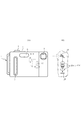
図1(A)は各実施の形態に共通するデジタルカメラ1の正面図、(B)は側面透視図、図2は背面図である。このデジタルカメラ1の本体2には、その上面部に半押し機能を備えたレリーズ釦(シャッタースイッチ)3と電源スイッチ4とが配置されており、正面部にはグリップ部5、ストロボ6及び撮像レンズ部の受光窓7が配置されている。また、背面部には、撮影モードと再生モードとを切り替えるためのモード切替スイッチ8、ズーム操作キー9、カーソルキー10、決定/OKキー11、手振れ量表示のオン・オフキーとして兼用されるDISPキー12、メニューキー13、及び、電子ファインダとしても機能するLCDからなる表示部14が配置されている。この表示部14には、モードに応じてブレ量の表示部14aが表示される。また、内部には図1(B)で図示されるように、垂直方向の角速度を検出する第1角速度センサ16と水平方向の角加速度を検出する第2角速度センサ17が配置されているとともに、回転式ミラー18、レンズ群19及び撮像素子20等が配置されている。
Hereinafter, an embodiment of the present invention will be described with reference to the drawings.
(First embodiment)
1A is a front view of a
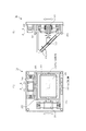
図3(A)は前記回転式ミラー18の正面図、(B)は側面図である。この回転式ミラー18は、電磁ボイスコイルによる回転ミラーであって、垂直なYaw回転軸181に上下中央部を固定されたYaw回転ジンバル182と、このYaw回転ジンバル182の左右中央部に設けられたPitch回転軸183と、このPitch回転軸183に両側中央部を固定されて、Yaw回転ジンバル182内に配置されたPitch回転ジンバル184とが設けられ、このPitch回転ジンバル184にミラー185が配置されている。そして、Yaw駆動用VCM(ボイスコイルモータ)アクチュエータ186のムーバーとYaw回転軸181間に設けられたラック&ピニオン(図示せず)により、ムーバーが左右方向に直線移動することにより、Yaw回転ジンバル182がYaw回転軸181を中心に回転駆動される。また、Pitch駆動用VCMアクチュエータ187のムーバーとPitch回転軸183間に設けられたラック&ピニオン(図示せず)により、ムーバーが上下方向に直線移動することにより、Pitch回転ジンバル184がPitch回転軸183を中心に回転駆動されるように構成されている。
3A is a front view of the
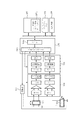
図4は、デジタルカメラ1の具体的回路構成を示すブロック図である。図において、操作部23は、前記レリーズ釦3や電源スイッチ4等の図1及び図2に示したスイッチやキー群等で構成され、このスイッチ及びキー群の操作情報は、入力回路24を介して、制御部25に入力される。制御部25は、CPU及びその周辺回路と、CPUの作業用メモリであるRAM等から構成されるマイクロコンピュータであり、各部を制御する。
FIG. 4 is a block diagram showing a specific circuit configuration of the
この制御部25には、表示メモリ26、表示駆動ブロック27、画像バッファメモリ28、画像信号処理部29、圧縮符号化/伸長復号化部30、静止画/動画画像メモリ31、時計回路70、プログラムメモリ32、データメモリ33、メモリIF34、外部I/Oインターフェース35、通信制御ブロック36、電源制御ブロック37及び撮影制御部38が接続されている。表示メモリ26には、表示部14に表示される各種表示データが一時的に記憶される。表示駆動ブロック27は、前記表示部14を駆動し、画像バッファメモリ28は、画像データを処理する際等において一時的に格納する。
The
画像信号処理部29は、後述する撮像素子から制御部25が取り込んだ画像信号に対する各種処理を実行するDSPからなる。圧縮符号化/伸長復号化部30は、この画像信号処理部で処理された画像データを記録時には伸長処理し、記録した画像データを再生する際には伸長復号化する。静止画/動画画像メモリ31は、レリーズ釦3の操作により撮像された画像データ(静止画像データ)を記録保存する。時計回路70は、現在時刻を計時して制御部25に供給する。プログラムメモリ32は、後述するフローチャートに示す制御部25の制御プログラム、及び「人物撮影モード」「夜景撮影モード」等の撮影シーン毎の撮影制御プログラム、撮影シーン毎の対象被写体の種別情報、該対象被写体の種別に対応する特徴量データ等が記憶されている。
The image
データメモリ33には、シーン別の撮影条件設定データメモリ331、ユーザの手ブレ実績データメモリ332、及び手ブレ補正設定データメモリ333が設けられている。メモリIF34は、着脱自在な外部メモリ媒体39に接続されている。外部I/Oインターフェース35は、USBコネクタ40に接続され、通信制御ブロック36は無線LAN等送受信部41を介してアンテナ42に接続され、電源制御ブロック37には、電池43が接続されている。電池43からの電力は電源制御ブロック37及び制御部25を介して各部に供給される。
The
前記撮影制御部38には、前記ストロボ6の照射角を駆動する照射各駆動部44、照射を駆動するストロボ照明駆動部45とが接続されているとともに、測光、測距センサ46の受光角を駆動する受光角駆動部47、測光、測距センサ46から色温度を検出して出力する色温度検出部48、測光データを検出して出力する測光部49及び測距データを検出して出力する測距部50が接続されている。さらに前記撮影制御部38には、前記第1及び第2角速度センサ17、17が各々角速度検出部51、52、積分器53、54を介して接続されている。
The
一方、ズームレンズユニット55には、前記回転式ミラー18、レンズ群19及び撮像素子20が配置されているとともに、この回転式ミラー18を回転駆動する駆動機構56、前記レンズ群19中に介挿された絞り57が設けられており、また、撮像素子20の前面にはシャッター58が配置されている。
On the other hand, the zoom lens unit 55 is provided with the
さらに、前記撮影制御部38には、電動ミラーY方向駆動部59、電動ミラーX方向駆動部60、フォーカスレンズ駆動部61、ズームレンズ駆動部62、絞り駆動部63、シャッター駆動部64、映像信号処理部65及びタイミング制御&ドライバ66が接続されている。電動ミラーY方向駆動部59は、駆動機構56を駆動して回転式ミラー18を上下方向に動作させるものであり、電動ミラーX方向駆動部60は左右方向に動作させるものである。フォーカスレンズ駆動部61は、レンズ群19中のフォーカスレンズを駆動するものであり、ズームレンズ駆動部62は、ズーム操作キー9の操作に応じて被写体像を拡大または縮小すべくレンズ群19中ズームレンズを駆動するものである。また、 絞り駆動部63は前記絞り57を駆動するものであり、シャッター駆動部64は前記シャッター58を駆動するものである。前記映像信号処理部65は、撮像素子20からのアナログ信号をデジタル信号に変換するA/D回路及びこのA/D回路からのデジタル撮像信号を保持するCDSと、CDSから撮像信号を供給されるアナログアンプであるゲイン調整アンプ(AGC)等からなる。
Further, the photographing
図5は、前記シーン別の撮影条件設定データメモリ331及びユーザの手ブレ実績データメモリ332の構成を示す概念図である。シーン別の撮影条件設定データメモリ331には、「人物」、「風景」等の撮影シーン又は被写体に応じて、サンプル画像と撮影条件設定データ(シーン別撮影プログラム)が記憶されている。撮影条件設定データは、EVシフト(露出補正)、ストロボ、ホワイトバランス、ISO感度・・・等でからなる。また、ユーザの手ブレ実績データメモリ332には、ユーザA、ユーザB、ユーザC等のユーザを示す情報毎に、各撮影シーン又は被写体及び撮影条件設定データに対応して、両加速度センサ51、52により検出された当該ユーザにおけるデジタルカメラ1の垂直方向及び水平方向のブレ量が更新されつつ記録される。
FIG. 5 is a conceptual diagram showing configurations of the scene-specific shooting condition setting
図6は本実施の形態の処理手順を示すフローチャートである。制御部25がプログラムメモリ32に格納されているプログラムに基づき各部を制御することにより、デジタルカメラ1はこのフローチャートに示すように動作する。先ず、ユーザによる操作部23での操作よって、撮影モードが設定されたか否かを判断する(ステップS101)。撮影モードが設定されず、その他のモードが設定された場合には、設定されたモードに応じてその他のモード処理を実行する(ステップS102)。
FIG. 6 is a flowchart showing the processing procedure of the present embodiment. When the
撮影モードが設定された場合には、シーン別の撮影条件設定データメモリ331から選択された撮影シーン又は被写体に応じて、この撮影条件設定データメモリ331に記憶されている撮影条件設定データ(シーン別撮影プログラム)に基づき撮影条件を設定する(ステップS103)。例えば、撮影モードとして「人物」が選択された場合には、EVシフト(露出補正):±0、ストロボ:オート、ホワイトバランス:オート、ISO感度:オート・・・等が設定されることとなる。また、この撮影条件の設定に際しては、ユーザA、ユーザB、ユーザCのように、当該撮影者を特定する情報も操作部23での操作に応じて設定する。
When the shooting mode is set, the shooting condition setting data (by scene) stored in the shooting condition setting
次に、測光処理、AF処理を実行し(ステップS104)、被写体像のスルー画像を表示部14に表示させる(ステップS105)。したがって、ユーザはこの表示部14に表示されたスルー画像を見ながら、このデジタルカメラ1の向きを調整する。また、レリーズ釦3が半押しされたか否かを判断し(ステップS106)、レリーズ釦3が半押しされない場合には、その他のキー処理を実行する(ステップS107)。
Next, photometric processing and AF processing are executed (step S104), and a through image of the subject image is displayed on the display unit 14 (step S105). Therefore, the user adjusts the direction of the
ユーザによりレリーズ釦3が半押しされると、ステップS106の判断がYESとなり、ステップS106からステップS108に進んで、両加速度センサ51、52により検出されている当該デジタルカメラ1の垂直方向及び水平方向のブレ量を検出して、データメモリ33に順次記録する(ステップS108)。また、測光処理、AF処理を実行する(ステップS109)
When the
次に、撮影条件に対応する前回までのブレ量評価値を読み出す(ステップS110)。つまり、前記ステップS103で撮影シーン又は被写体として「人物」が選択されて、これに対応する撮影条件設定データメモリ331の撮影条件が設定され、かつ、ユーザAが設定されたとすると、ユーザの手ブレ実績データメモリ332からユーザAのブレ量評価値(ユーザ別のブレ量データ)を読み出す。
Next, the previous blur amount evaluation value corresponding to the shooting condition is read (step S110). That is, assuming that “person” is selected as the shooting scene or subject in step S103, the shooting conditions in the shooting condition setting
なお、本実施の形態においては、手ブレ実績データメモリ332にユーザ別のブレ量データを記録するようにしたが、ユーザ別の手ブレの特徴量を記録するようにしてもよく、この場合には手ブレの特徴量がブレ量評価値として読み出されることとなる。
In this embodiment, the shake amount data for each user is recorded in the camera shake
そして、このステップS110で読み出した当該ユーザにおける当該撮影条件のブレ評価値が所定値以上であるか否かを判断する(ステップS111)。この判断がNOであって、当該ユーザにおける当該撮影条件のブレ評価値が所定値未満である場合には、当該ユーザの当該撮影条件における手ブレは少なく、手ブレ補正は必要ないものと推定される。よって、この場合には、手ブレ補正機能をOFFに設定する。 Then, it is determined whether or not the blur evaluation value of the shooting condition for the user read in step S110 is equal to or greater than a predetermined value (step S111). If this determination is NO and the blur evaluation value of the shooting condition for the user is less than a predetermined value, it is estimated that the camera shake in the shooting condition of the user is small and no camera shake correction is necessary. The Therefore, in this case, the camera shake correction function is set to OFF.
これにより、当該ユーザが手ブレが少ない撮影条件で撮影を行った場合において、無用な手ブレ補正機能が動作することを防止することができる。 Thereby, when the user performs shooting under shooting conditions with less camera shake, it is possible to prevent an unnecessary camera shake correction function from operating.
また、ステップS111での判断の結果、当該撮影条件のブレ量評価値が所定値以上である場合には、手ブレ補正機能をONに設定して、回転式ミラー18、電動ミラーY方向駆動部59及び電動ミラーX方向駆動部60等で構成される手ブレ補正装置を起動させる(ステップS113)。
Further, as a result of the determination in step S111, when the blur amount evaluation value of the photographing condition is equal to or greater than a predetermined value, the camera shake correction function is set to ON, and the
したがって、ユーザ個人毎に異なる熟練度や手ブレ発生の度合いに応じて、ブレ補正を行うことができる。よって、不要なブレ補正に起因して処理時間や処理負担が大きくなってしまうことなく、ユーザに応じて適切にブレ補正機能を発生させることができる。 Therefore, it is possible to perform blur correction according to the skill level and the degree of occurrence of camera shake that are different for each user. Therefore, the blur correction function can be appropriately generated according to the user without increasing the processing time and the processing burden due to unnecessary blur correction.
また、ステップS113に続くステップS114では、半押しされているレリーズ釦3が全押しされたか否かを判断し、全押しされなかった場合にはステップS106に戻る。そして、ユーザが半押ししていたレリーズ釦3を全押しすると、ステップS114の判断がYESとなる。したがって、ステップS114からステップS115に進み、測光値と露出条件に応じて露出タイマーを設定し、タイマー計時を開始する(ステップS115)。また、両加速度センサ16、17により検出されている当該デジタルカメラ1の垂直方向及び水平方向(Yaw/Pitch方向)のブレ量を検出して、データメモリ33に順次記録する(ステップS116)。
In step S114 following step S113, it is determined whether or not the
次に、手ブレ補正機能がONとなっているか否かを判断する(ステップS117)。前記ステップS112の処理が実行されて手ブレ補正機能がOFFとなっている場合には、ステップS118及びステップS119の処理を実行することなく、ステップS120に進む。前記ステップS113の処理が実行されることより、手ブレ補正機能がONとなっている場合には、前記ステップS116で検出したYaw/Pitch方向のブレ量から、Yaw/Pitch方向のブレ補正量を算出して、手ブレ補正設定データメモリ333に記憶させる(ステップS118)。そして、この算出して手ブレ補正設定データメモリ333に記憶したブレ補正量に応じて、Yaw/Pitch方向の手ブレ補正装置、つまり電動ミラーY方向駆動部59及び電動ミラーX方向駆動部60を駆動して、ブレ補正処理を実行する(ステップS119)。
Next, it is determined whether or not the camera shake correction function is ON (step S117). When the process of step S112 is executed and the camera shake correction function is OFF, the process proceeds to step S120 without executing the processes of step S118 and step S119. If the camera shake correction function is ON by executing the process of step S113, the shake correction amount in the Yaw / Pitch direction is calculated from the shake amount in the Yaw / Pitch direction detected in step S116. This is calculated and stored in the camera shake correction setting data memory 333 (step S118). Then, in accordance with the shake correction amount calculated and stored in the camera shake correction setting
図7(A)〜(C)は、本実施の形態における手ブレ検出時のミラー185の動作態様を示すものであり、図7(A)は手ブレが発生していない状態、同図(B)は手ブレが生じた状態、同図(C)は手ブレ補正を行った状態を示すものである。すなわち、図7(A)の状態から、同図(B)に示すように手ブレが生じ、その結果、光軸Pが+θ°ずれたP'となった際には、レンズ群19、絞り57、及び、シャッター58を介して撮像素子20に導かれるRもR'にずれ、Dの差だけブレが生じる。この場合、前記ステップS119での処理により、同図(C)に示すように、+θ°に応じて、ミラー185を−θ/2°だけ回転させることにより、手ブレを補正し、R"を撮像素子20に導くことができる。
FIGS. 7A to 7C show an operation mode of the
そして、前記ステップS103で設定された撮影条件に応じて露出/撮影動作を開始し(ステップS120)、このステップS120での処理により、シャッター58が開いて撮像素子20が露出状態となる。次に、前記露出タイマーにより計時している露出時間が終了となったか否か、つまり露出タイマーの残時間が「0」となったか否かを判断し(ステップS121)、露出時間が終了となってない場合には、ステップS116に戻って、このステップS116からの処理を繰り返し実行する。露出時間が終了したならば、露出/撮影動作を停止させてシャッター58を閉じるとともに、手ブレ検出(角速度センサ16、17、角速度検出部51、52、積分器53、54)、手ブレ補正装置(電動ミラーY方向駆動部59及び電動ミラーX方向駆動部60)を停止させる(ステップS122)
Then, the exposure / photographing operation is started according to the photographing condition set in step S103 (step S120), and the
さらに、撮影画像を圧縮、符号化し、この圧縮、符号化した撮影画像を外部メモリ媒体39に記録するとともに(ステップS123)、撮影画像をレビュー表示する(ステップS124)。さらに、撮影モード、撮影条件、ユーザ毎にブレ量データを集計して評価値を更新する(ステップS125)。 Further, the captured image is compressed and encoded, and the compressed and encoded captured image is recorded in the external memory medium 39 (step S123), and the captured image is displayed for review (step S124). Further, the blur amount data is totaled for each photographing mode, photographing condition, and user, and the evaluation value is updated (step S125).
すなわち、今回の撮影がユーザAによるものであって、撮影モードとして「人物」が選択され、撮影条件としてEVシフト(露出補正):±0、ストロボ:オート、ホワイトバランス:オート、ISO感度:オート・・・等が設定されたとすると、ユーザの手ブレ実績データメモリ332において、図5に示した領域332Aに記録されているユーザAの評価値を、前記ステップS116で検出し順次記録したYaw/Pitch方向のブレ量、あるいはこのブレ量に基づく評価値に更新する。
That is, the current shooting is by user A, “person” is selected as the shooting mode, EV shift (exposure correction): ± 0, strobe: auto, white balance: auto, ISO sensitivity: auto as shooting conditions. ... Is set, the evaluation value of the user A recorded in the
したがって、ユーザの手ブレ実績データメモリ332のデータは、当該ユーザが撮影を行う毎に更新され、この更新されるデータに基づきステップS111の判断が行われることとなる。これにより、ユーザの最新データに基づき、当該ユーザが当該撮影条件で撮影を行う際にブレ補正機能をONにするかOFFにするかを制御することができ、的確にブレ補正機能をON、OFF制御を行うことができる。
Therefore, the data in the camera shake
なお、本実施の形態においては、ステップS125で評価値を更新するようにしたが、評価値やブレ量に基づきシーン別の撮影条件設定データメモリ331における撮影条件設定データを更新するようにしてもよい。つまり、ステップS116で検出記録した手ブレ量に応じて、撮影条件設定データメモリ331の撮影条件設定データを変更することにより、手ブレ量に応じた手ブレ補正効果が発生するような撮影条件で撮影を行うことができ、撮影条件によっても適切な手ブレ補正効果を得ることができる。
In this embodiment, the evaluation value is updated in step S125. However, the shooting condition setting data in the shooting condition setting
図8は、前記角速度センサ16、17の具体的構成例を示す図である。本例は、セラミックバイモルフ振動子を用いた圧電式の振動ジャイロ81であり、支持ピン(兼リード線)81a、圧電素子82を有している。この振動ジャイロ81は、HPF82、LPF83等に接続されて回路構成される。振動ジャイロ81では、各図(C)に示すような回路によって、回転によって生ずるコリオリの力を圧電素子で電圧信号に変換し、角速度に比例した電圧を検出できる。手ブレ検出に用いる場合には、動かない地面上に立って撮影する場合、一般に3〜10Hz程度の手ブレが多いが、歩きながら撮影する場合にはやや高い10〜18Hz程度、列車や車両に乗って撮影する場合には20〜25Hz程度のブレも発生するので、0.5〜25Hz程度のブレの発生に対応できるように、応答性:50Hz、検出範囲±360deg/sec程度の超小型センサが利用できる。
FIG. 8 is a diagram showing a specific configuration example of the
また、周囲温度の変化による静止時出力の温度ドリフトを除去するために、センサ出力に(カットオフ周波数fc=0.3〜0.5Hz程度の)HPF(ハイパスフィルタ)を接続してDC成分を除去し、またセンサ内部の振動ノイズ(20〜25Hz付近等)を除去するために、応答周波数以上の高周波成分を除去する(カットオフ周波数fc=1kHz〜4kHz程度の)LPF(ローパスフィルタ)を接続する。手ブレによる振動をジャイロにより角速度信号として検出し、マイコン回路などで積分演算して角度変位に変換し、角速度及び角度変位に基づいて手ブレ補正量を決定することができる。 In addition, in order to remove the temperature drift of the stationary output due to the change in ambient temperature, an HPF (high pass filter) (with a cutoff frequency fc = 0.3 to 0.5 Hz) is connected to the sensor output, and the DC component is An LPF (low-pass filter) that removes high-frequency components above the response frequency (with a cut-off frequency of about fc = 1 kHz to 4 kHz) is connected to remove the vibration noise inside the sensor (around 20 to 25 Hz). To do. Vibration due to camera shake can be detected as an angular velocity signal by a gyro, integrated and calculated by a microcomputer circuit or the like, converted into angular displacement, and a camera shake correction amount can be determined based on the angular velocity and angular displacement.
図9は、手ブレ量の検出回路の具体的構成例を示す図である。図に示すように、Yaw方向角速度センサ(振動ジャイロ)101、Pitch方向角速度センサ(振動ジャイロ)102には、駆動部103が接続されているとともに、センサ検出回路部104及びデジタル信号処理部105を介して制御部106に接続されている。制御部106は、入出力インタフェース1061、CPU1062等を備え、データメモリ109、プログラムメモリ108、時計回路109が接続されており、データメモリ109にはユーザ別の手ブレ実績データメモリ1071が設けられている。前記センサ検出部104は、各角速度センサ101、102毎に設けられたHPF、差動アンプ、LPF、A/D変換器D構成され、前記デジタル信号処理部105は、各角速度センサ101、102毎に設けられたHPF、位相補償回路、積分回路で構成されている。
FIG. 9 is a diagram illustrating a specific configuration example of a camera shake amount detection circuit. As shown in the figure, a
かかる手ブレ量の検出回路を用いることにより、図10(a)に例示する手ブレの振動波形や、同図(b−1)に例示する手ブレの周波数特性(未習熟者、静止撮影時)、(b−2)に例示する手ブレの周波数特性(未習熟者、移動撮影時)をユーザ別の手ブレ実績データメモリ1071に記録することができる。
By using such a camera shake amount detection circuit, the vibration waveform of camera shake illustrated in FIG. 10A and the frequency characteristics of camera shake illustrated in FIG. ) And (b-2), the frequency characteristics of camera shake (unexperienced person, during moving shooting) can be recorded in the camera shake
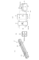
図11(A)〜(C)は、ブレ補正装置の他の構成例であって、電磁ローレンツ力によるMEMS回動ミラー式のブレ補正装置を示す図である。図11(A)に図示するように、シリコン基盤などのMEMS基盤201には、外側回転台202と内側回転台203とが各々トーションバー(ねじりバネ)204を介して架装されており、前記内側回転台203にミラー205装着されている。また、このMEMS基盤201は、図11(B)、及び、この図11(B)における線A―A'における断面図である図11(C)に図示するように、前記外側回転台202に取り付けられ、この外側回転台202の四周部には、各々磁石206が配置され、プリント基板207、ヨーク208が設けられているとともに、前記プリント基板207に接続されたコネクタ210が設けられている。
FIGS. 11A to 11C are diagrams illustrating another example of the configuration of the shake correction device, which is a MEMS rotation mirror type shake correction device using an electromagnetic Lorentz force. As shown in FIG. 11A, an
したがって、係るブレ補正装置によれば、前記図3に示した回転式ミラーよりも薄型化が可能であることから、小型のデジタルカメラにも容易に実装することができる。 Therefore, according to the shake correction apparatus, it is possible to make it thinner than the rotary mirror shown in FIG. 3, and therefore it can be easily mounted on a small digital camera.
(第2の実施の形態)
図12は、本発明の他の実施の形態における処理手順を示すフローチャートである。この実施の形態は、撮影後に画像を印刷する印刷用紙サイズや表示部14の画面大きさなど、再生出力時の画像サイズに応じて、許容ブレ量を算出し、それに基づいてブレ軽減撮影を行うようにするものである。
(Second Embodiment)
FIG. 12 is a flowchart showing a processing procedure in another embodiment of the present invention. In this embodiment, an allowable blur amount is calculated according to the image size at the time of reproduction output, such as the size of the printing paper on which an image is printed after shooting and the screen size of the
制御部25はプログラムメモリ32に格納されているプログラムに基づき、このフローチャートに従って処理を実行する。先ず、露出設定時間Tなど、撮影条件を設定するとともに(ステップS201)、ユーザによる操作部23での操作に応じて印刷用紙のサイズを選択する(ステップS202)。さらに、ユーザによる操作部23での操作により、「印刷した画像を当該印刷用紙の対角距離から観賞する」が選択されたか否かを判断する(ステップS203)。これが選択された場合には、下記例示式を用いて画像サイズYに応じて、許容ボケδを設定する(ステップS204)。
(例)許容ボケδ=(画像サイズY/用紙サイズSp)×用紙サイズSp×tan(3′)=Y×tan(3′)
The
(Example) Allowable blur δ = (image size Y / paper size Sp) × paper size Sp × tan (3 ′) = Y × tan (3 ′)
「印刷した画像を当該印刷用紙の対角距離から観賞する」が選択されず、「一定の明視距離から観賞する」が選択された場合には、下記例示式を用いて印刷用紙サイズSpに応じて許容ボケδを設定する(ステップS205)。
(例)許容ボケδ=(Y/Sp)×250(mm)×tan(3′)
When “Appreciate the printed image from the diagonal distance of the printing paper” is not selected and “Appreciate from a certain clear viewing distance” is selected, the printing paper size Sp is set using the following exemplary formula. Accordingly, the allowable blur δ is set (step S205).
(Example) Allowable blur δ = (Y / Sp) × 250 (mm) × tan (3 ′)
次に、測光処理、ズーム処理、AF処理を実行し(ステップS206)、レンズ焦点距離情報(f)読み込む(ステップS207)。そして、下記例示式を用い、許容ボケ量δと、レンズ焦点距離f、及び、設定露出時間T(秒)に応じて、許容ブレ量を設定する(ステップS208)。
(例)許容ブレ量(角度)θB=2×tan−1(δ/2f)
許容ブレ量(角速度)ωB=θB/T
Next, photometric processing, zoom processing, and AF processing are executed (step S206), and lens focal length information (f) is read (step S207). Then, using the following exemplary formula, an allowable blur amount is set according to the allowable blur amount δ, the lens focal length f, and the set exposure time T (seconds) (step S208).
(Example) Allowable blurring amount (angle) θB = 2 × tan−1 (δ / 2f)
Allowable blurring amount (angular velocity) ωB = θB / T
このように、前記許容ブレ量は、例えは、撮像サイズ(対角)Yに応じて、若しくは、査撮像サイズYと印刷用紙への引き伸ばし倍率とに応じて、許容ボケ(許容錯乱円径)δを求め、許容ボケδと撮影レンズの焦点距離fに応じて、許容ボケδに相当する画角を、許容できるブレ角度θとして求める。 In this way, the allowable blur amount is, for example, allowable blur (permissible circle of confusion) according to the imaging size (diagonal) Y or according to the inspection imaging size Y and the enlargement magnification to the printing paper. δ is obtained, and an angle of view corresponding to the allowable blur δ is determined as an allowable blur angle θ according to the allowable blur δ and the focal length f of the photographing lens.
すなわち、撮影画角θは、焦点距離f(mm)と画像サイズ(対角)Y(mm)とから、画角θ=2×tan−1(Y/2f)、
ブレとボケでは見え方や印象は異なるが、同程度の寸法で許容できると見なした場合には、許容ブレ角度(θB)/画角(θ)=許容ボケ(δ)/画像サイズ(Y)と、略比例すると考えることができ、
許容ブレ角度θB=2×tan−1(δ/2f)
許容ブレ角速度ωB=許容ブレ角度θB/露出時間T=2×tan−1(δ/2f)/T、
と設定できる。
That is, the shooting angle of view θ is calculated from the focal length f (mm) and the image size (diagonal) Y (mm), and the angle of view θ = 2 × tan−1 (Y / 2f),
Although the appearance and impression are different between blur and blur, if it is considered acceptable with the same size, allowable blur angle (θB) / angle of view (θ) = allowable blur (δ) / image size (Y )
Allowable blur angle θB = 2 × tan−1 (δ / 2f)
Permissible blur angular velocity ωB = allowable blur angle θB / exposure time T = 2 × tan−1 (δ / 2f) / T,
Can be set.
そして、予めデータメモリ33に記憶されている当該ユーザのブレ量(角度θ、角速度ω)を読み込み、許容ブレ量(角度θB、角速度ωB)と比較して(ステップS209)、θ≧θB、又はω≧ωBであるか否かを判断する(ステップS210)。この判断の結果、θ≧θB、又はω≧ωBであり、当該ユーザのブレ量が許容ブレ以上である場合には、手ブレ補正が必要と判断し、手ブレ補正をONにする(ステップS112)。また、θ≧θB、又はω≧ωBではなく、当該ユーザのブレ量が許容ブレ未満である場合には、手ブレ補正が不要と判断し、手ブレ補正をOFFにする(ステップS211)。
Then, the blur amount (angle θ, angular velocity ω) of the user stored in advance in the
つまり、本実施の形態においては、当該ユーザの手ブレ量が許容ブレ量以上であるか未満であるかにより、手ブレ補正をON・OFFすることから、より精度よく手ブレ撮影を防止しつつ、無用な手ブレ補正機能の動作を防止することができる。 In other words, in the present embodiment, the camera shake correction is turned ON / OFF depending on whether the camera shake amount of the user is greater than or less than the allowable shake amount, thereby preventing camera shake shooting more accurately. Unnecessary camera shake correction function can be prevented from operating.
(第3の実施の形態) (Third embodiment)
なお、図12に示したフローチャートにおいては省略したが、この実施の形態においても、前述した第1の実施の形態と同様に、S114〜S125の処理が実行され、撮影画像が圧縮符号化されて、外部メモリ媒体39に記憶されることとなる。したがって、第1及び第2の実施の形態においては、撮影された画像がブレ補正処理されることなく外部メモリ媒体39に記憶されるが、この第3の実施の形態は撮影された画像をブレ補正処理してから外部メモリ媒体39に記録するものである。
Although omitted in the flowchart shown in FIG. 12, in this embodiment as well, the processing of S114 to S125 is executed and the captured image is compressed and encoded as in the first embodiment described above. It is stored in the
図13は、本実施の形態においてメモリ媒体33に撮影された画像を記録する直前実効されるブレ補正処理の処理内容を示すフローチャートである。まず、概略について説明すると、撮影した画像に対し、フーリエ変換、離散フーリエ変換(DFT)を施し(ステップS601)、劣化画像のフーリエ変換画像を生成する(ステップS602)。また、PSF法、ゼロクロス法、又はHough変換法、逆フィルター法等で、p(u,v)又はPSFを推定し(ステップS603)、直線ブレの評価値、ブレ方向角度(θ)、ブレ距離(L)を算出する(ステップS604)。また、直線ブレ(θ方向に周期1/Lでゼロ交差)をP(u,v)=sin(πfL)/πfL、(f=ucosθ+vsinθ)により算出し(ステップS605)、I(u,v)=G(u,v)/P(u,v)を演算し(ステップS609)、i(x,y)=Σu=0M−1Σv=0n−1I(u,v)W1−uxW2−vy(ただし、W1=exp(−j2π/M)、W2=exp(−j2π/N))により逆フーリエ変換する(ステップS610)。
FIG. 13 is a flowchart showing the processing content of the blur correction processing that is performed immediately before recording a photographed image in the
あるいは、同様にPSF法、ゼロクロス法、又はHough変換法、逆フィルター法等で、p(u,v)又はPSFを推定し(ステップS606)、直線ボケの評価値、焦点の広がり半径(r)の計算を行う(ステップS607)。また、焦点ボケ(周期1.01π/rで、同心円状のゼロ交差)をP(u,v)=2・J1(r−R)/r・R、(J1=1時の第1種ベッセル関数)により算出し(ステップS608)、前記ステップS609及びS610の処理を実行する。 Alternatively, p (u, v) or PSF is similarly estimated by the PSF method, zero-cross method, Hough transform method, inverse filter method, or the like (step S606), the evaluation value of the linear blur, the radius of the focus spread (r) Is calculated (step S607). Further, the defocus (the concentric zero crossing with a cycle of 1.01π / r) is P (u, v) = 2 · J1 (r−R) / r · R, (the first kind Bessel when J1 = 1). Function) (step S608), and the processes of steps S609 and S610 are executed.
すなわち、本実施の形態は、ブレが生じた画像、若しくは焦点ボケが生じた画像など劣化画像を、フーリエ変換などにより周波数領域の画像信号に変換した後、ブレやボケを生じさせたPSF(焦点分布関数、点広がり関数)を推定し、推定されたPSF関数に基づいて、周波数領域の劣化画像に対して、推定されたPSF関数を逆関数などで演算し、得られた周波数領域の画像を逆フーリエ変換などにより空間領域の画像信号に戻すことにより、ブレ画像やボケ画像の補正処理や画像の復元を行うものである。 That is, in the present embodiment, after a deteriorated image such as an image with blurring or an image with defocusing is converted into an image signal in the frequency domain by Fourier transform or the like, a PSF (focal point) with blurring or defocusing is generated. Distribution function, point spread function), and based on the estimated PSF function, the estimated PSF function is calculated with an inverse function on the degraded image in the frequency domain, and the obtained frequency domain image is obtained. By returning to the image signal of the spatial domain by inverse Fourier transform or the like, the blurring image or the blurred image is corrected and the image is restored.
一般に、PSF法による画像復元では、ブレやボケのない本来の画像i(x,y)が、ブレやボケを生じさせる劣化成分p(x,y)により劣化した画像を劣化画像と見なして、
g(x、y)=p(x,y)*i(x,y) (*はコンボリューション(畳み込み積分)演算である)とすると、
p(x,y)をPSF(Point Spread Function、点像分布関数)や、LSF(Line Spread Function、線分布関数)などとして求めて、劣化させたブレやボケの劣化成分p(x,y)を推定し、p(x,y)がうまく推定できれば、本来の画像i(x,y)をデコンボリューション(逆畳み込み積分)演算により画像復元できる方法である。
In general, in the image restoration by the PSF method, an original image i (x, y) free from blurring and blurring is regarded as a degraded image by degrading the degradation component p (x, y) that causes blurring and blurring.
If g (x, y) = p (x, y) * i (x, y) (* is a convolution operation),
p (x, y) is obtained as PSF (Point Spread Function), LSF (Line Spread Function), etc. If p (x, y) can be estimated well, the original image i (x, y) can be restored by deconvolution (deconvolution integration).
つまり、撮影画像など劣化した画像g(x、y)を、フーリエ変換などで周波数軸に変換し、G[u,v]を求めると、
G[u,v]=P[u,v]・I[u,v](コンボリューションは、周波数軸上では、フーリエ変換同士のかけ算となる)であるので、その劣化成分P[u,v]を周波数領域で推定し、P[u,v]が推定できれば、逆フィルタとして、1/P[u,v]を計算して求め、G[u,v]に乗算すれば、以下のように、本来の画像i(x,y)を演算により復元できる。
I[u,v]=G[u,v]/P[u,v](フーリエ変換同士の割り算)
i(x,y)=逆フーリエ変換{I[u,v]}
=Σu=0M−1Σv=0n−1・I(u,v)W1uxW2vy(ただし、W1=exp(−j2π/M)、W2=exp(−j2π/N))、
That is, when a deteriorated image g (x, y) such as a photographed image is converted into a frequency axis by Fourier transform or the like, and G [u, v] is obtained,
Since G [u, v] = P [u, v] · I [u, v] (convolution is multiplication of Fourier transforms on the frequency axis), the degradation component P [u, v ] In the frequency domain and if P [u, v] can be estimated, 1 / P [u, v] is calculated and obtained as an inverse filter, and G [u, v] is multiplied as follows. In addition, the original image i (x, y) can be restored by calculation.
I [u, v] = G [u, v] / P [u, v] (division between Fourier transforms)
i (x, y) = inverse Fourier transform {I [u, v]}
= Σu = 0M−1Σv = 0n−1 · I (u, v) W1uxW2vy (W1 = exp (−j2π / M), W2 = exp (−j2π / N)),
ちなみに、画像(x,y)のフーリエ変換F[u,v]は、離散フーリエ変換(DFT)では、
F[u,v]=(1/MN)Σx=0M−1Σv=0N−1f(x,y)W1uxW2vy
(ただし、W1=exp(−j2π/M)、W2=exp(−j2π/N))
Incidentally, the Fourier transform F [u, v] of the image (x, y) is the discrete Fourier transform (DFT).
F [u, v] = (1 / MN) Σx = 0M−1Σv = 0N−1f (x, y) W1uxW2vy
(W1 = exp (−j2π / M), W2 = exp (−j2π / N))
離散コサイン変換(DCT)では、
F[u,v]=(4√MN)C(u)C(v)・ΣxΣvf(x,y)・cos{(2x+ 1)uπ/2M}cos{(2y+1)uπ/2N}
ただし、C(u)、C(v)=1√2(u,v=0)、C(u)、C(v)=1(u,v≠0)
等で計算できるが、高速フーリエ変換(FFT)用バタフライ型演算など、各種の高速計算アルゴリズムが開発されているので、それらを利用してもよい。
In the discrete cosine transform (DCT),
F [u, v] = (4√MN) C (u) C (v) ・ ΣxΣvf (x, y) · cos {(2x + 1) uπ / 2M} cos {(2y + 1) uπ / 2N}
However, C (u), C (v) = 1√2 (u, v = 0), C (u), C (v) = 1 (u, v ≠ 0)
However, various high-speed calculation algorithms such as butterfly type computation for fast Fourier transform (FFT) have been developed, and these may be used.
以下では、このPSF法におけるPSFやP[u,v]の推定方法を、直線ブレ量の推定や焦点や焦点ボケ量の推定に用いて、推定された直線ブレ量の推定や焦点ボケ量に基づいて、「直線ブレ」画像や「焦点ボケ」画像を復元する例で説明する。一般に、ブレやボケのない画像f(x,y)をフーリエ変換したG[u,v]の振幅の分布は、前記ステップS602における(b)のようにな直線ブレのパターンとなり、中央付近の高周波成分がブレ角度に従って、数本の細長い傾斜した楕円状に抜けたり歪んだりしたパターンが現れる。 In the following, the estimation method of PSF and P [u, v] in this PSF method is used for estimation of linear blur amount and estimation of focus and defocus amount. Based on this, an example of restoring a “straight line blur” image and a “focus blur” image will be described. In general, the amplitude distribution of G [u, v] obtained by Fourier transforming an image f (x, y) without blurring or blurring becomes a straight blurring pattern as shown in (b) in step S602, and is near the center. Depending on the blur angle, several high-frequency components appear in the form of several elongated slanted ellipses that are distorted or distorted.
また、焦点ボケした劣化画像g(x、y)をフーリエ変換したG[u,v]は、(d)のような焦点ボケパターンとなり、中央部の高周波成分が同心円状に抜けたり歪んだりしたパターンとなる。同様に、直線ブレと焦点ボケが共に生ずると、(c)のような、両方の特徴を合わせ持ったパターンとなる。 Further, G [u, v] obtained by Fourier transform of the defocused degraded image g (x, y) becomes a defocused pattern as shown in (d), and the high-frequency component in the center part is missing or distorted in a concentric manner. It becomes a pattern. Similarly, when both straight blurring and out-of-focus blur occur, a pattern having both features is obtained as shown in FIG.
(PSF法によるブレ方向とブレ距離の推定)
図14は、従来のPSF法での、ブレ方向(θ)とブレ距離(L)、焦点ボケの広がり半径(r)の推定方法であり、ブレ方向(θ)は、G[u,v]の縦/横の相対比(R)から算出し、また、ブレ距離(L)若しくは焦点広がり半径(r)は、復元画像iL、iL+1を順次計算して求め、その相関値C(L)から逆算するか、相関値C(L)が所定値以上の相関度に飽和するまで繰り返して求める。しかし、この方法では、計算に時間がかかるので、次のような多階調Hough換算で求める方法もある。
(Estimation of blur direction and blur distance by PSF method)
FIG. 14 shows an estimation method of the blur direction (θ), blur distance (L), and spread radius (r) of the focal blur in the conventional PSF method. The blur direction (θ) is G [u, v]. The blur distance (L) or the focal spread radius (r) is obtained by sequentially calculating the restored images iL and iL + 1 and calculated from the correlation value C (L). The calculation is repeated until the correlation value C (L) is saturated to a degree of correlation equal to or greater than a predetermined value. However, since this method takes time to calculate, there is also a method of obtaining in the following multi-gradation Hough conversion.
図15は、PSF法と多階調Hough換算によるブレ方向(θ)、ブレ距離(L)若しくは、焦点ボケの広がり半径(r)の推定方法を示す図である。直線ブレなどの劣化画像G[u,v]のフリーエ・スペクトルの中央部の円内を、(複数点を通る直線の推定や検出などに広く用いられる)Hough換算法により、θ−ρ空間上の多階調の二次元画像に変換し、H(θ,ρ)値の角度θ毎に切り出したHθ(ρ)波形を比較して、
そのエントロピー E(θ)=ΣρPlog2(1/P)(0°≦θ<180°)を求め、
E(θ)が最小となる角度θが、直線ブレ方向(θ)と推定できる。
(ただし、P=(θ,ρ)/HSUM(θ)、HSUM(θ)は円内画素値の合計で、HSUM(θ=Σ(−R≦0≦R)H(θ,ρ)である。)
また、ぶれた方向(θ)のHθ(ρ)波形の極小点の周期(T1)を求めると、ブレ距離(L)=1/TLが求まる。
FIG. 15 is a diagram illustrating a method of estimating the blur direction (θ), the blur distance (L), or the spread radius (r) of the focal blur by PSF method and multi-gradation Hough conversion. A circle in the center of the free spectrum of the degraded image G [u, v] such as straight line blurring is expressed in the θ-ρ space by the Hough conversion method (used widely for estimation and detection of straight lines passing through a plurality of points). And a Hθ (ρ) waveform cut out for each angle θ of the H (θ, ρ) value.
The entropy E (θ) = ΣρPlog2 (1 / P) (0 ° ≦ θ <180 °) is obtained,
The angle θ at which E (θ) is minimized can be estimated as the linear blur direction (θ).
(However, P = (θ, ρ) / HSUM (θ), HSUM (θ) is the sum of the in-circle pixel values, and is HSUM (θ = Σ (−R ≦ 0 ≦ R) H (θ, ρ)). .)
Further, when the period (T1) of the minimum point of the Hθ (ρ) waveform in the blur direction (θ) is obtained, the blur distance (L) = 1 / TL is obtained.
また、H(θ,ρ)をθ軸方向に0°〜179°まで平均化したC(ρ)波形、
C(ρ)=ΣρHθ(ρ)/180(0°≦θ<180°)
を作成し、C(θ)波形の極小点の周期(Tr)から、焦点ボケの広がりの半径(r)は、
半径(r)=1.01×π×Trより求まる。
MN)C(u)C(v)・ΣxΣvf(x,y)・cos{(2x+1)uπ/2M}cos{(2y+1)uπ/2N}
Further, a C (ρ) waveform obtained by averaging H (θ, ρ) from 0 ° to 179 ° in the θ-axis direction,
C (ρ) = ΣρHθ (ρ) / 180 (0 ° ≦ θ <180 °)
From the period (Tr) of the minimum point of the C (θ) waveform, the radius (r) of the focal blur spread is
Radius (r) = 1.01 × π × Tr
MN) C (u) C (v) .ΣxΣvf (x, y) .cos {(2x + 1) uπ / 2M} cos {(2y + 1) uπ / 2N}
(Hough換算)
ちなみに、Hough換算(ハフ変換、ヒュー変換とも呼ぶ)では、(ρ=x/cosθ+y・sinθ)の変換式により、一般に二次元座標x−y平面上の点は、θ−ρ明面上の曲線に、また、x−y平面上の直線は、θ−ρ明面上の点に、それぞれ変換、逆変換できる。例えば、x−y平面上の点A,B,Cを通る直線Lを求めたい場合には、点A,B,Cを変換した、θ−ρ平面上の曲線A′,B′,C′が交差する交点P(θ,ρ)を求めると、その点P(θ1,ρ1)を、x−y平面上に逆変換し、ゼロ点から下ろした垂線の長さがρLで、垂線の角度がθLとなる直線Lが、求める直線である。
(Hough conversion)
By the way, in Hough conversion (also called Hough conversion or Hugh conversion), a point on a two-dimensional coordinate xy plane is generally a curve on a θ-ρ bright surface by a conversion formula of (ρ = x / cos θ + y · sin θ). In addition, a straight line on the xy plane can be converted and inversely converted to a point on the θ-ρ bright surface, respectively. For example, when it is desired to obtain a straight line L passing through points A, B, and C on the xy plane, curves A ′, B ′, and C ′ on the θ-ρ plane obtained by converting the points A, B, and C are used. When the intersection point P (θ, ρ) intersecting is obtained, the point P (θ1, ρ1) is inversely transformed on the xy plane, the length of the perpendicular line dropped from the zero point is ρL, and the angle of the perpendicular line Is a straight line to be obtained.
Hough換算は、このように二次元画像の中から直線領域を抽出する等、画像処理分野では広く用いられているので、詳細は省略するが、前述の多階調Hough換算では、このHough換算の配列H(θ,ρ)の明度(階調を持つ輝度や濃度)を、H(θ,ρ)=f(x,y)として、多階調の二次元画像として定義し、前述のような複数曲線の交点を求める場合には、明度(階調値)を加算して、階調値が最も大きくなる点を交点として、近似計算により迅速に求めることができる。 The Hough conversion is widely used in the field of image processing, such as extracting a straight line region from a two-dimensional image in this way, so the details are omitted, but in the above multi-gradation Hough conversion, this Hough conversion The brightness (brightness or density having gradation) of the array H (θ, ρ) is defined as a multi-gradation two-dimensional image with H (θ, ρ) = f (x, y), as described above. When calculating the intersection of a plurality of curves, brightness (gradation value) is added, and the point at which the gradation value becomes the maximum can be used as an intersection to quickly determine by approximation calculation.
前述のように、ゼロクロス法、あるいは、多階調Hough換算等により、劣化画像g(x、y)を周波数軸上にフーリエ変換したG[u,v]から、直線ブレ画像の方向(角度θ)と直線ブレの距離(画素数L)、あるいは、焦点ボケ画像の焦点広がり半径(画素数r)を、前記のような演算により推定し、これらに基づいて、画像処理により、ブレを補正したり、ブレの少ない画像を復元したりすることができる。 As described above, the direction (angle θ) of the linear blur image is obtained from G [u, v] obtained by Fourier transforming the degraded image g (x, y) on the frequency axis by the zero cross method or multi-gradation Hough conversion. ) And the straight blurring distance (number of pixels L), or the focal spread radius (number of pixels r) of the defocused image is estimated by the above-described calculation, and based on these, the blurring is corrected by image processing. Or restore an image with less blur.
なお、データメモリ33に記録されるブレ情報としては、手ブレ量や像ブレの実績データに限らず、ブレの頻度、方向、振動波形、波形の特徴、周波数成分、フーリエ変換係数など検出された手ブレの特徴データ、又は像ブレの頻度、画像の動きベクトル、解像度、コントラスト、ヒストグラム、画像の周波数特性、フーリエ変換やDCT変換など、撮影された画像の評価データなどを記録するようにしてもよい。
Note that the blur information recorded in the
また、手ブレ量や像ブレ量が所定の閾値を超えたときの撮影条件(被写輝度、露出時間、焦点距離、撮影距離、ストロボ条件)や、その累積点数などを記録して、制御を簡素化したり、記録データ量を圧縮するようにしてもよい。 Also, record the shooting conditions (shooting brightness, exposure time, focal length, shooting distance, strobe conditions) when the amount of camera shake or image blur exceeds a predetermined threshold, and the cumulative score. It may be simplified or the amount of recorded data may be compressed.
又は、当該個人ユーザにおける、手ブレ量や像ブレ量の記録データに基づいて、その経年経時変化や習熟度、撮影条件毎のデータなどから、時期の所定の撮影条件における手ブレ量や像ブレ量などを予測演算して、予測した手ブレ量や像ブレ量に応じて、補正モードや補正パラメータを自動設定するようにしてもよい。 Alternatively, based on the recorded data of the camera shake amount and image shake amount of the individual user, the camera shake amount and image shake under the predetermined shooting conditions of the time are determined from the secular change, proficiency level, and data for each shooting condition. An amount or the like may be predicted and calculated, and the correction mode and the correction parameter may be automatically set according to the predicted camera shake amount and image blur amount.
また、図4に示したように、デジタルカメラ1は、通信制御ブロック36、無線LAN等送受信部41を有している。したがって、これらを利用しデジタルカメラ1がネットワークを介しメーカーのサーバーに接続された場合には、カメラ内メモリから個人ユーザ別に、手ブレや像ブレの実績データ(や画像特徴データ、撮影条件データ、得点データ)などをサーバーに自動的に送信し、サーバーでは、個人別又は撮影条件別に、前記の手ブレ実績データをデータベースに集計記録し、個人ユーザ別又は撮影条件別に、ブレ特性を管理、分析し、多数ユーザからの集計分析データに基づいて、カメラの制御プログラムや補正パラメータを更新して書き込めるように構成してもよい。
As shown in FIG. 4, the
また、実施の形態において、図1に示した外部構造のデジタルカメラ1に本発明を適用するようにしたが、これに限ることなく、静止画及び動画撮影機能を備えた携帯電話、大型のデジタルカメラ、本体と蓋体とからなり一方にLCDファインダーを備え他方にモニターを備える二つ折りのデジタルカメラ、ユーザの操作により当該ユーザ自身を撮影可能なデジタルカメラ、隣接した二つの画面を有し両画面に連続する単一のスルー画像を表示させるデジタルカメラ等、他の構造からなる撮像装置、あるいは撮像機能を備えた携帯電話等の各種機器に本発明を適用することができる。
In the embodiment, the present invention is applied to the
1 デジタルカメラ
2 本体
3 レリーズ釦
14 表示部
16 第1加速度センサ
17 第2角速度センサ
18 回転式ミラー
19 レンズ群
20 撮像素子
23 操作部
24 入力回路
25 制御部
26 表示メモリ
27 表示駆動ブロック
28 画像バッファメモリ
29 画像信号処理部
30 圧縮符号化/伸長復号化部
31 静止画/動画画像メモリ
32 プログラムメモリ
33 データメモリ
38 撮影制御部
39 外部メモリ媒体
51 角速度検出部
65 映像信号処理部
331 撮影条件設定データメモリ
332 手ブレ実績データメモリ
DESCRIPTION OF
Claims (9)
この撮影手段が撮影する画像のブレを補正するブレ補正手段と、
カメラ本体のブレを検出するブレ検出手段と、
このブレ検出手段により検出された前記カメラ本体のブレを示すブレ情報を当該カメラに設定される撮影条件に対応させて記憶するブレ情報記憶手段と、
前記カメラに設定された撮影条件に応じて、前記ブレ情報記憶手段から対応するブレ情報を取得する取得手段と、
この取得手段により取得されたブレ情報に基づき、前記ブレ補正手段の動作を制御する制御手段と
を備えることを特徴とするカメラ。 Photographing means;
A blur correction unit that corrects blur of an image captured by the shooting unit;
Blur detection means for detecting camera shake,
Blur information storage means for storing blur information indicating blur of the camera body detected by the blur detection means in correspondence with shooting conditions set in the camera;
An acquisition unit configured to acquire corresponding blur information from the blur information storage unit in accordance with a shooting condition set in the camera;
A camera comprising: control means for controlling the operation of the shake correction means based on the shake information acquired by the acquisition means.
前記取得手段により取得されたブレ情報に基づき、前記撮影手段が撮影する画像のブレを補正すべきか否かを判断する補正判断手段を備え、
この補正判断手段の判断結果に応じて、前記ブレ補正手段を動作又は停止させることを特徴とする請求項1記載のカメラ。 The control means includes
Based on the blur information acquired by the acquisition unit, a correction determination unit that determines whether or not to correct blur of an image captured by the imaging unit,
2. The camera according to claim 1, wherein the blur correction unit is operated or stopped according to a determination result of the correction determination unit.
前記取得手段により取得されたブレ情報が示すブレ量が許容ブレ量以上であるか否かを判断するブレ量判断手段を備え、
このブレ量判断手段の判断結果に応じて、前記ブレ補正手段を動作又は停止させることを特徴とする請求項1記載のカメラ。 The control means includes
A blur amount determining unit that determines whether or not a blur amount indicated by the blur information acquired by the acquiring unit is greater than or equal to an allowable blur amount;
2. The camera according to claim 1, wherein the blur correction unit is operated or stopped according to a determination result of the blur amount determination unit.
前記ブレ検出手段により検出された前記カメラ本体のブレを示すブレ情報を当該カメラに設定される撮影条件に対応させて記憶するブレ情報記憶手段と、
前記カメラに設定された撮影条件に応じて、前記ブレ情報記憶手段から対応するブレ情報を取得する取得手段と、
この取得手段により取得されたブレ情報に基づき、前記ブレ補正手段の動作を制御する制御手段と
して機能させることを特徴とするカメラ制御プログラム。 A computer having a camera comprising: an imaging unit; a blur correction unit that corrects blur of an image captured by the imaging unit; and a blur detection unit that detects blur of the camera body;
Blur information storage means for storing blur information indicating blur of the camera body detected by the blur detection means in correspondence with shooting conditions set in the camera;
An acquisition unit that acquires corresponding blur information from the blur information storage unit according to the shooting conditions set in the camera;
A camera control program that functions as a control unit that controls the operation of the blur correction unit based on the blur information acquired by the acquisition unit.
前記ブレ検出手段により検出された前記カメラ本体のブレを示すブレ情報を当該カメラに設定される撮影条件に対応させて記憶手段に記憶するブレ情報記憶ステップと、
前記カメラに設定された撮影条件に応じて、前記記憶手段から対応するブレ情報を取得する取得ステップと、
この取得手段ステップにより取得されたブレ情報に基づき、前記ブレ補正手段の動作を制御する制御ステップと
を含むことを特徴とするカメラ制御方法。 A camera control method comprising: an imaging unit; a blur correction unit that corrects blur of an image captured by the imaging unit; and a blur detection unit that detects blur of the camera body,
A blur information storage step for storing blur information indicating blur of the camera body detected by the blur detection unit in a storage unit in association with shooting conditions set in the camera;
An acquisition step of acquiring corresponding blur information from the storage unit according to the shooting conditions set in the camera;
And a control step for controlling the operation of the shake correcting means based on the shake information acquired by the acquiring means step.
Priority Applications (1)
| Application Number | Priority Date | Filing Date | Title |
|---|---|---|---|
| JP2008089578A JP2009244490A (en) | 2008-03-31 | 2008-03-31 | Camera, camera control program and camera control method |
Applications Claiming Priority (1)
| Application Number | Priority Date | Filing Date | Title |
|---|---|---|---|
| JP2008089578A JP2009244490A (en) | 2008-03-31 | 2008-03-31 | Camera, camera control program and camera control method |
Publications (2)
| Publication Number | Publication Date |
|---|---|
| JP2009244490A true JP2009244490A (en) | 2009-10-22 |
| JP2009244490A5 JP2009244490A5 (en) | 2011-05-06 |
Family
ID=41306462
Family Applications (1)
| Application Number | Title | Priority Date | Filing Date |
|---|---|---|---|
| JP2008089578A Pending JP2009244490A (en) | 2008-03-31 | 2008-03-31 | Camera, camera control program and camera control method |
Country Status (1)
| Country | Link |
|---|---|
| JP (1) | JP2009244490A (en) |
Cited By (6)
| Publication number | Priority date | Publication date | Assignee | Title |
|---|---|---|---|---|
| WO2011096157A1 (en) * | 2010-02-02 | 2011-08-11 | パナソニック株式会社 | Imaging device and method, and image processing method for imaging device |
| JP2012014458A (en) * | 2010-06-30 | 2012-01-19 | Toshiba Tec Corp | Traffic line processing device, method and program |
| WO2012056686A1 (en) * | 2010-10-27 | 2012-05-03 | パナソニック株式会社 | 3d image interpolation device, 3d imaging device, and 3d image interpolation method |
| JP2016533691A (en) * | 2014-08-28 | 2016-10-27 | シャオミ・インコーポレイテッド | Imaging method, imaging apparatus, program, and storage medium |
| WO2017146000A1 (en) * | 2016-02-24 | 2017-08-31 | 富士フイルム株式会社 | Drive device, antivibration device and binoculars |
| EP4006623A4 (en) * | 2019-07-31 | 2022-10-05 | Huawei Technologies Co., Ltd. | Optical anti-shake apparatus and control method |
Citations (4)
| Publication number | Priority date | Publication date | Assignee | Title |
|---|---|---|---|---|
| JPH0456831A (en) * | 1990-06-22 | 1992-02-24 | Canon Inc | Image blurring preventing device |
| JP2002016837A (en) * | 2000-04-26 | 2002-01-18 | Matsushita Electric Ind Co Ltd | Imaging apparatus |
| JP2005181712A (en) * | 2003-12-19 | 2005-07-07 | Nikon Corp | Camera shake correction system |
| JP2006023631A (en) * | 2004-07-09 | 2006-01-26 | Pentax Corp | Camera with image blurring correction function |
-
2008
- 2008-03-31 JP JP2008089578A patent/JP2009244490A/en active Pending
Patent Citations (4)
| Publication number | Priority date | Publication date | Assignee | Title |
|---|---|---|---|---|
| JPH0456831A (en) * | 1990-06-22 | 1992-02-24 | Canon Inc | Image blurring preventing device |
| JP2002016837A (en) * | 2000-04-26 | 2002-01-18 | Matsushita Electric Ind Co Ltd | Imaging apparatus |
| JP2005181712A (en) * | 2003-12-19 | 2005-07-07 | Nikon Corp | Camera shake correction system |
| JP2006023631A (en) * | 2004-07-09 | 2006-01-26 | Pentax Corp | Camera with image blurring correction function |
Cited By (14)
| Publication number | Priority date | Publication date | Assignee | Title |
|---|---|---|---|---|
| US8553091B2 (en) | 2010-02-02 | 2013-10-08 | Panasonic Corporation | Imaging device and method, and image processing method for imaging device |
| JP2011159159A (en) * | 2010-02-02 | 2011-08-18 | Panasonic Corp | Imaging device and method, and image processing method for imaging device |
| WO2011096157A1 (en) * | 2010-02-02 | 2011-08-11 | パナソニック株式会社 | Imaging device and method, and image processing method for imaging device |
| JP2012014458A (en) * | 2010-06-30 | 2012-01-19 | Toshiba Tec Corp | Traffic line processing device, method and program |
| CN102687515B (en) * | 2010-10-27 | 2015-07-15 | 杜比国际公司 | 3D image interpolation device,3d imaging device,and 3d image interpolation method |
| CN102687515A (en) * | 2010-10-27 | 2012-09-19 | 松下电器产业株式会社 | 3D image interpolation device,3d imaging device,and 3d image interpolation method |
| WO2012056686A1 (en) * | 2010-10-27 | 2012-05-03 | パナソニック株式会社 | 3d image interpolation device, 3d imaging device, and 3d image interpolation method |
| US9270970B2 (en) | 2010-10-27 | 2016-02-23 | Dolby International Ab | Device apparatus and method for 3D image interpolation based on a degree of similarity between a motion vector and a range motion vector |
| JP5887267B2 (en) * | 2010-10-27 | 2016-03-16 | ドルビー・インターナショナル・アーベー | 3D image interpolation apparatus, 3D imaging apparatus, and 3D image interpolation method |
| JP2016533691A (en) * | 2014-08-28 | 2016-10-27 | シャオミ・インコーポレイテッド | Imaging method, imaging apparatus, program, and storage medium |
| US9661223B2 (en) | 2014-08-28 | 2017-05-23 | Xiaomi Inc. | Method and device for photographing including camera shake |
| WO2017146000A1 (en) * | 2016-02-24 | 2017-08-31 | 富士フイルム株式会社 | Drive device, antivibration device and binoculars |
| JPWO2017146000A1 (en) * | 2016-02-24 | 2018-10-11 | 富士フイルム株式会社 | Vibration isolator and binoculars |
| EP4006623A4 (en) * | 2019-07-31 | 2022-10-05 | Huawei Technologies Co., Ltd. | Optical anti-shake apparatus and control method |
Similar Documents
| Publication | Publication Date | Title |
|---|---|---|
| TWI386040B (en) | Image pickup apparatus equipped with function of detecting image shaking | |
| US8279293B2 (en) | Image stabilizing apparatus and image pickup apparatus | |
| JP5011387B2 (en) | Imaging device | |
| JP4968885B2 (en) | IMAGING DEVICE AND ITS CONTROL METHOD, IMAGING SYSTEM, IMAGE PROCESSING METHOD, AND PROGRAM | |
| JP2008035308A (en) | Electronic camera and lens unit | |
| JP4466430B2 (en) | Electronic camera and imaging control program | |
| US20020047906A1 (en) | Photographing apparatus having variable image blur correction control characteristics for still photography and motion picture photography | |
| JP2014126860A (en) | Optical device, imaging device and control method of the same, program, storage medium | |
| KR20150061561A (en) | An image pickup apparatus and control method | |
| JP2009244490A (en) | Camera, camera control program and camera control method | |
| JP2008145662A (en) | Imaging apparatus and adjusting method thereof | |
| JP2017129785A (en) | Imaging device, and image tremor correction method | |
| US10735655B2 (en) | Apparatus, method, and program for image processing | |
| JP3646124B2 (en) | Autofocus device | |
| JP4930579B2 (en) | Electronic camera, imaging control method and program | |
| EP3151544B1 (en) | Filter control device, filter control method, and imaging device | |
| JP6395401B2 (en) | Image shake correction apparatus, control method therefor, optical apparatus, and imaging apparatus | |
| CN111698416B (en) | Image processing apparatus, image processing method, and storage medium | |
| JP2012247544A (en) | Imaging device, program, and shake correction method of imaging device | |
| JP2012042589A (en) | Image shake correction mechanism, lens barrel, and image sensor | |
| JP5182395B2 (en) | Imaging apparatus, imaging method, and imaging program | |
| JPWO2006043315A1 (en) | IMAGING DEVICE AND PORTABLE DEVICE HAVING IMAGING DEVICE | |
| JP2017032653A (en) | Image blur correction device, control method thereof, imaging apparatus, and optical apparatus | |
| JP6711099B2 (en) | Imaging device | |
| JP2010016650A (en) | Imaging apparatus, control method thereof and program |
Legal Events
| Date | Code | Title | Description |
|---|---|---|---|
| A521 | Request for written amendment filed |
Free format text: JAPANESE INTERMEDIATE CODE: A523 Effective date: 20110323 |
|
| A621 | Written request for application examination |
Free format text: JAPANESE INTERMEDIATE CODE: A621 Effective date: 20110323 |
|
| A977 | Report on retrieval |
Free format text: JAPANESE INTERMEDIATE CODE: A971007 Effective date: 20120412 |
|
| A131 | Notification of reasons for refusal |
Free format text: JAPANESE INTERMEDIATE CODE: A131 Effective date: 20120424 |
|
| A521 | Request for written amendment filed |
Free format text: JAPANESE INTERMEDIATE CODE: A523 Effective date: 20120621 |
|
| A131 | Notification of reasons for refusal |
Free format text: JAPANESE INTERMEDIATE CODE: A131 Effective date: 20121127 |
|
| A02 | Decision of refusal |
Free format text: JAPANESE INTERMEDIATE CODE: A02 Effective date: 20130402 |