JP2009222068A - Clutch-by-wire system - Google Patents
Clutch-by-wire system Download PDFInfo
- Publication number
- JP2009222068A JP2009222068A JP2008063797A JP2008063797A JP2009222068A JP 2009222068 A JP2009222068 A JP 2009222068A JP 2008063797 A JP2008063797 A JP 2008063797A JP 2008063797 A JP2008063797 A JP 2008063797A JP 2009222068 A JP2009222068 A JP 2009222068A
- Authority
- JP
- Japan
- Prior art keywords
- clutch
- shift
- actuator
- wire system
- sensor
- Prior art date
- Legal status (The legal status is an assumption and is not a legal conclusion. Google has not performed a legal analysis and makes no representation as to the accuracy of the status listed.)
- Withdrawn
Links
Images


Classifications
-
- F—MECHANICAL ENGINEERING; LIGHTING; HEATING; WEAPONS; BLASTING
- F16—ENGINEERING ELEMENTS AND UNITS; GENERAL MEASURES FOR PRODUCING AND MAINTAINING EFFECTIVE FUNCTIONING OF MACHINES OR INSTALLATIONS; THERMAL INSULATION IN GENERAL
- F16H—GEARING
- F16H61/00—Control functions within control units of change-speed- or reversing-gearings for conveying rotary motion ; Control of exclusively fluid gearing, friction gearing, gearings with endless flexible members or other particular types of gearing
- F16H61/02—Control functions within control units of change-speed- or reversing-gearings for conveying rotary motion ; Control of exclusively fluid gearing, friction gearing, gearings with endless flexible members or other particular types of gearing characterised by the signals used
- F16H61/0202—Control functions within control units of change-speed- or reversing-gearings for conveying rotary motion ; Control of exclusively fluid gearing, friction gearing, gearings with endless flexible members or other particular types of gearing characterised by the signals used the signals being electric
- F16H61/0248—Control units where shifting is directly initiated by the driver, e.g. semi-automatic transmissions
-
- F—MECHANICAL ENGINEERING; LIGHTING; HEATING; WEAPONS; BLASTING
- F16—ENGINEERING ELEMENTS AND UNITS; GENERAL MEASURES FOR PRODUCING AND MAINTAINING EFFECTIVE FUNCTIONING OF MACHINES OR INSTALLATIONS; THERMAL INSULATION IN GENERAL
- F16D—COUPLINGS FOR TRANSMITTING ROTATION; CLUTCHES; BRAKES
- F16D48/00—External control of clutches
- F16D48/06—Control by electric or electronic means, e.g. of fluid pressure
-
- F—MECHANICAL ENGINEERING; LIGHTING; HEATING; WEAPONS; BLASTING
- F16—ENGINEERING ELEMENTS AND UNITS; GENERAL MEASURES FOR PRODUCING AND MAINTAINING EFFECTIVE FUNCTIONING OF MACHINES OR INSTALLATIONS; THERMAL INSULATION IN GENERAL
- F16H—GEARING
- F16H61/00—Control functions within control units of change-speed- or reversing-gearings for conveying rotary motion ; Control of exclusively fluid gearing, friction gearing, gearings with endless flexible members or other particular types of gearing
- F16H61/18—Preventing unintentional or unsafe shift, e.g. preventing manual shift from highest gear to reverse gear
-
- F—MECHANICAL ENGINEERING; LIGHTING; HEATING; WEAPONS; BLASTING
- F16—ENGINEERING ELEMENTS AND UNITS; GENERAL MEASURES FOR PRODUCING AND MAINTAINING EFFECTIVE FUNCTIONING OF MACHINES OR INSTALLATIONS; THERMAL INSULATION IN GENERAL
- F16D—COUPLINGS FOR TRANSMITTING ROTATION; CLUTCHES; BRAKES
- F16D2500/00—External control of clutches by electric or electronic means
- F16D2500/30—Signal inputs
- F16D2500/308—Signal inputs from the transmission
- F16D2500/30806—Engaged transmission ratio
-
- F—MECHANICAL ENGINEERING; LIGHTING; HEATING; WEAPONS; BLASTING
- F16—ENGINEERING ELEMENTS AND UNITS; GENERAL MEASURES FOR PRODUCING AND MAINTAINING EFFECTIVE FUNCTIONING OF MACHINES OR INSTALLATIONS; THERMAL INSULATION IN GENERAL
- F16D—COUPLINGS FOR TRANSMITTING ROTATION; CLUTCHES; BRAKES
- F16D2500/00—External control of clutches by electric or electronic means
- F16D2500/30—Signal inputs
- F16D2500/314—Signal inputs from the user
- F16D2500/31406—Signal inputs from the user input from pedals
- F16D2500/31413—Clutch pedal position
-
- F—MECHANICAL ENGINEERING; LIGHTING; HEATING; WEAPONS; BLASTING
- F16—ENGINEERING ELEMENTS AND UNITS; GENERAL MEASURES FOR PRODUCING AND MAINTAINING EFFECTIVE FUNCTIONING OF MACHINES OR INSTALLATIONS; THERMAL INSULATION IN GENERAL
- F16D—COUPLINGS FOR TRANSMITTING ROTATION; CLUTCHES; BRAKES
- F16D2500/00—External control of clutches by electric or electronic means
- F16D2500/30—Signal inputs
- F16D2500/314—Signal inputs from the user
- F16D2500/3146—Signal inputs from the user input from levers
- F16D2500/31466—Gear lever
-
- F—MECHANICAL ENGINEERING; LIGHTING; HEATING; WEAPONS; BLASTING
- F16—ENGINEERING ELEMENTS AND UNITS; GENERAL MEASURES FOR PRODUCING AND MAINTAINING EFFECTIVE FUNCTIONING OF MACHINES OR INSTALLATIONS; THERMAL INSULATION IN GENERAL
- F16D—COUPLINGS FOR TRANSMITTING ROTATION; CLUTCHES; BRAKES
- F16D2500/00—External control of clutches by electric or electronic means
- F16D2500/50—Problem to be solved by the control system
- F16D2500/512—Relating to the driver
- F16D2500/5126—Improving response to driver inputs
-
- F—MECHANICAL ENGINEERING; LIGHTING; HEATING; WEAPONS; BLASTING
- F16—ENGINEERING ELEMENTS AND UNITS; GENERAL MEASURES FOR PRODUCING AND MAINTAINING EFFECTIVE FUNCTIONING OF MACHINES OR INSTALLATIONS; THERMAL INSULATION IN GENERAL
- F16D—COUPLINGS FOR TRANSMITTING ROTATION; CLUTCHES; BRAKES
- F16D2500/00—External control of clutches by electric or electronic means
- F16D2500/70—Details about the implementation of the control system
- F16D2500/704—Output parameters from the control unit; Target parameters to be controlled
- F16D2500/70402—Actuator parameters
- F16D2500/7041—Position
-
- F—MECHANICAL ENGINEERING; LIGHTING; HEATING; WEAPONS; BLASTING
- F16—ENGINEERING ELEMENTS AND UNITS; GENERAL MEASURES FOR PRODUCING AND MAINTAINING EFFECTIVE FUNCTIONING OF MACHINES OR INSTALLATIONS; THERMAL INSULATION IN GENERAL
- F16D—COUPLINGS FOR TRANSMITTING ROTATION; CLUTCHES; BRAKES
- F16D2500/00—External control of clutches by electric or electronic means
- F16D2500/70—Details about the implementation of the control system
- F16D2500/704—Output parameters from the control unit; Target parameters to be controlled
- F16D2500/70464—Transmission parameters
- F16D2500/70488—Selection of the gear ratio
-
- F—MECHANICAL ENGINEERING; LIGHTING; HEATING; WEAPONS; BLASTING
- F16—ENGINEERING ELEMENTS AND UNITS; GENERAL MEASURES FOR PRODUCING AND MAINTAINING EFFECTIVE FUNCTIONING OF MACHINES OR INSTALLATIONS; THERMAL INSULATION IN GENERAL
- F16D—COUPLINGS FOR TRANSMITTING ROTATION; CLUTCHES; BRAKES
- F16D2500/00—External control of clutches by electric or electronic means
- F16D2500/70—Details about the implementation of the control system
- F16D2500/71—Actions
- F16D2500/7101—Driver alarm
Landscapes
- Engineering & Computer Science (AREA)
- General Engineering & Computer Science (AREA)
- Mechanical Engineering (AREA)
- Physics & Mathematics (AREA)
- Fluid Mechanics (AREA)
- Hydraulic Clutches, Magnetic Clutches, Fluid Clutches, And Fluid Joints (AREA)
- Control Of Transmission Device (AREA)
- Arrangement And Mounting Of Devices That Control Transmission Of Motive Force (AREA)
Abstract
Description
本発明は、自動クラッチ及び自動変速機を制御する変速制御装置を備えたクラッチバイワイヤシステムに関し、特に、手動変速及び自動変速の切り替え可能なクラッチバイワイヤシステムに関する。 The present invention relates to a clutch-by-wire system provided with a shift control device for controlling an automatic clutch and an automatic transmission, and more particularly to a clutch-by-wire system capable of switching between manual shift and automatic shift.
一台の車両で運転者の要求に応じてオートマチックかマニュアルかを切り替えることができる車両がある。このような車両においては、エンジンが自動クラッチを介して自動変速機に接続され、自動クラッチ及び自動変速機が変速制御装置によって制御され、変速制御装置にて手動変速及び自動変速の切り替え可能なクラッチバイワイヤシステムを有する。 There is a vehicle that can switch between automatic and manual according to a driver's request with a single vehicle. In such a vehicle, an engine is connected to an automatic transmission via an automatic clutch, the automatic clutch and the automatic transmission are controlled by a transmission control device, and a clutch that can be switched between manual transmission and automatic transmission by the transmission control device. Has a by-wire system.
従来のクラッチバイワイヤシステムに関して、エンジンの出力を変速して車両の駆動輪側へ伝達する変速部を含み、変速部が自動モードと手動モードとの間でモード選択可能である車両用パワートレインの制御装置が、エンジンと駆動輪との間の動力伝達経路上に設けられたクラッチの締結度合を運転者によるクラッチペダルの操作に基づき電気的に制御可能なクラッチバイワイヤ手段と、変速部のモードが手動モードのときにクラッチの締結度合制御をONにし自動モードのときにクラッチの締結度合制御をOFFにするクラッチバイワイヤ制御手段とを具えるものが開示されている(特許文献1参照)。これにより、例えば、夫はマニュアル車が欲しいが妻はオートマチック車が欲しい、あるいは通常の走行中はマニュアル車が良いが渋滞時はオートマチック車の方が良い等の要求に一台の車両で応えることができる。 2. Description of the Related Art Conventional clutch-by-wire system includes a transmission unit that shifts the output of an engine and transmits the output to a drive wheel side of the vehicle, and the transmission unit is capable of mode selection between an automatic mode and a manual mode. A clutch-by-wire means capable of electrically controlling the degree of engagement of a clutch provided on the power transmission path between the engine and the drive wheel based on the operation of the clutch pedal by the driver, and the mode of the transmission unit is manual There is disclosed a clutch-by-wire control means for turning on the clutch engagement degree control in the mode and turning off the clutch engagement degree control in the automatic mode (see Patent Document 1). This means, for example, that a husband wants a manual car but a wife wants an automatic car, or a normal car is better during normal driving, but an automatic car is better when there is traffic. Can do.
しかしながら、特許文献1記載の制御装置では、手動モードでは、発進・変速時のクラッチペダル操作について、イージードライブとスポーツドライブの両立を図っているものの、クラッチペダル操作とシフトレバー操作の関連については触れられていない。このことから、特許文献1記載の制御装置では、シフトレバー操作については、従来のマニュアルトランスミッションと同じと考えられる。すなわち、変速時にクラッチペダル(左足操作)、アクセルペダル(右足操作)、シフトレバー(左手操作)、ハンドル(右手操作)を連携し、適切なタイミングで操作することが想定され、対象がマニュアル車両の運転を楽しいと感じられるドライバに限定される。そのため、クラッチペダル操作とシフトレバー操作が不慣れなドライバが手動モードで操作すると、クラッチが繋がったまま変速するおそれがあり、変速部を破損してしまうおそれがある。また、手動モードでは、道路がカーブのところで変速操作すると、左手でシフトレバーを操作し、右手でハンドルを操作することになり、片手運転となるため、走行安全性が損なわれるおそれがある。
However, in the control device described in
本発明の主な課題は、手動変速モードにおいて、変速機を保護しつつ、走行安全性を向上させることができるクラッチバイワイヤシステムを提供することである。 The main subject of this invention is providing the clutch-by-wire system which can improve driving | running | working safety | security, protecting a transmission in manual transmission mode.
本発明の一視点においては、手動変速及び自動変速の切り替え可能なクラッチバイワイヤシステムであって、エンジンと接続されるクラッチ、及び、前記クラッチの解放及び係合を操作するクラッチアクチュエータを有する自動クラッチと、前記エンジンと前記クラッチを介して接続されるとともに、変速段の切り替えを操作するシフトアクチュエータを有する自動変速機と、クラッチペダルの踏み込み量を検出するクラッチペダルセンサと、シフトレバーの操作を検出するシフトセンサと、自動変速モードのときに、自動的に前記クラッチアクチュエータと前記シフトアクチュエータの動作を制御し、手動変速モードのときに、少なくとも前記クラッチペダルセンサ及び前記シフトセンサからの信号に基づいて、前記クラッチアクチュエータと前記シフトアクチュエータの動作を制御する変速制御装置と、を備えることを特徴とする。 In one aspect of the present invention, a clutch-by-wire system capable of switching between manual shift and automatic shift, and a clutch connected to an engine, and an automatic clutch having a clutch actuator for operating release and engagement of the clutch, , An automatic transmission having a shift actuator that is connected to the engine via the clutch and that operates to change gears, a clutch pedal sensor that detects the depression amount of the clutch pedal, and an operation of the shift lever The shift sensor automatically controls the operation of the clutch actuator and the shift actuator when in the automatic shift mode, and based on at least signals from the clutch pedal sensor and the shift sensor when in the manual shift mode, The clutch actuator Characterized in that it comprises a speed change control device for controlling the operation of the shift actuator and.
本発明によれば、手動変速モードのときに自動クラッチが繋がったままの状態で自動変速機を変速することを禁止できるため、自動変速機の破損を防止でき、自動変速機を保護することができる。また、手動変速モードのときに変速のタイミングを、クラッチペダルを踏み込むタイミングで決定できるため、変速の瞬間にハンドルを両手でしっかり握ることができ、走行安全性を向上させることができる。 According to the present invention, since it is possible to prohibit shifting of the automatic transmission while the automatic clutch is engaged in the manual shift mode, the automatic transmission can be prevented from being damaged and the automatic transmission can be protected. it can. In addition, since the timing of shifting can be determined by the timing of depressing the clutch pedal in the manual shifting mode, the handle can be firmly held with both hands at the moment of shifting, and driving safety can be improved.
本発明の実施形態では、エンジン(図1の10)と接続されるクラッチ(図1の21)、及び、前記クラッチ(図1の21)の解放及び係合を操作するクラッチアクチュエータ(図1の23)を有する自動クラッチ(図1の20)と、前記エンジン(図1の10)と前記クラッチ(図1の21)を介して接続されるとともに、変速段の切り替えを操作するシフトアクチュエータ(図1の34、35、36)を有する自動変速機(図1の30)と、クラッチペダルの踏み込み量を検出するクラッチペダルセンサ(図1の41)と、シフトレバーの操作を検出するシフトセンサ(図1の42)と、自動変速モードのときに、自動的に前記クラッチアクチュエータ(図1の23)と前記シフトアクチュエータ(図1の33、34、35)の動作を制御し、手動変速モードのときに、少なくとも前記クラッチペダルセンサ(図1の41)及び前記シフトセンサ(図1の42)からの信号に基づいて、前記クラッチアクチュエータ(図1の23)と前記シフトアクチュエータ(図1の33、34、35)の動作を制御する変速制御装置と、を備える。 In the embodiment of the present invention, a clutch (21 in FIG. 1) connected to an engine (10 in FIG. 1), and a clutch actuator (21 in FIG. 1) for operating release and engagement of the clutch (21 in FIG. 1). 23) and an automatic clutch (20 in FIG. 1), a shift actuator (FIG. 1 in FIG. 1) and a shift actuator (FIG. 1, 34, 35, 36), a clutch pedal sensor (41 in FIG. 1) for detecting the depression amount of the clutch pedal, and a shift sensor (41 in FIG. 1) for detecting the operation of the shift lever. 42) in FIG. 1 and in the automatic shift mode, the operation of the clutch actuator (23 in FIG. 1) and the shift actuator (33, 34, 35 in FIG. 1) is automatically controlled. In the manual shift mode, the clutch actuator (23 in FIG. 1) and the shift actuator based on at least signals from the clutch pedal sensor (41 in FIG. 1) and the shift sensor (42 in FIG. 1). And a shift control device that controls the operation of (33, 34, 35 in FIG. 1).
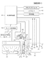
本発明の実施例1に係るクラッチバイワイヤシステムについて図面を用いて説明する。図1は、本発明の実施例1に係るクラッチバイワイヤシステムの構成を模式的に示した模式図である。
A clutch-by-wire system according to
クラッチバイワイヤシステムでは、エンジン(内燃機関)10の出力軸(クランクシャフト)と一体的に回転するフライホイール11に自動クラッチ20が組み付けられ、その自動クラッチ20を介して自動変速機30が接続されている。エンジン10は、エンジン制御装置50によって制御される。
In the clutch-by-wire system, an
自動クラッチ20は、機械式(乾燥単板式)の摩擦クラッチ21と、クラッチレバー22と、クラッチアクチュエータ23と、を備えている。自動クラッチ20は、乾式クラッチに限らず、電磁クラッチ、湿式クラッチなどを用いてもよい。
The
クラッチアクチュエータ23は、クラッチレバー22を介して摩擦クラッチ21による回転伝達を操作するアクチュエータである。
The
摩擦クラッチ21は、フライホイール11に対向して配置されており、自動変速機30の入力軸31と一体的に回転するクラッチディスク21aを備えている。摩擦クラッチ21は、フライホイール11に対するクラッチディスク21aの圧着荷重が変化されることで、フライホイール11及びクラッチディスク21a間(エンジン10の出力軸及び自動変速機30の入力軸31間)の回転伝達、すなわちクラッチトルクを変化させる。
The
クラッチアクチュエータ23は、その駆動源として直流電動モータ24を備え、同モータ24の駆動によりロッド25を前方又は後方に移動(進退)させてクラッチレバー22を動かす。これにより、クラッチレバー22を介してレリーズベアリング27を押動し、これに弾接するダイヤフラムスプリング28を変形させてプレッシャプレート29に圧着荷重を生ぜしめる。このプレッシャプレート29は、フライホイール11と一体回転する摩擦クラッチ21のカバー21bに支持されている。クラッチアクチュエータ23は、ロッド25を介してクラッチレバー22を動かすことで、プレッシャプレート29を介してフライホイール11に対するクラッチディスク21aの圧着荷重を変化させ、摩擦クラッチ21による回転伝達を操作する。
The
具体的には、ロッド25が前方に移動(進行)され、同ロッド25によりクラッチレバー22が図1の右側に押されると、フライホイール11に対するクラッチディスク21aの圧着荷重は低減されるようになっている。逆に、ロッド25が後方に移動(退行)され、クラッチレバー22が戻されると、フライホイール11に対するクラッチディスク21aの圧着荷重は増加されるようになっている。
Specifically, when the
ここで、ロッド25の移動位置と摩擦クラッチ21による回転伝達との関係について説明する。ロッド25を前方に移動(進行)させていくと、最終的にはフライホイール11に対するクラッチディスク21aの圧着荷重が略皆無となる。このとき、フライホイール11及びクラッチディスク21aは切り離されて、これらフライホイール11及びクラッチディスク21a間の回転伝達はなくなる。この回転伝達がなくなる状態をクラッチの断状態(非係合状態)という。そして、このときのロッド25の位置をスタンバイ点という。なお、ロッド25の位置に対応したその移動量を制御量としてのクラッチストローク(クラッチアクチュエータストローク)という。
Here, the relationship between the movement position of the
スタンバイ点からロッド25を後方に移動(退行)させていくと、フライホイール11に対するクラッチディスク21aの圧着荷重はその移動量に応じて増加する。このとき、圧着荷重に応じた回転数差(スリップ量)を有してフライホイール11及びクラッチディスク21a間の回転伝達がなされる。特に、このようなロッド25の移動(退行)による圧着荷重の増加により、回転数差(スリップ量)が略皆無となると、フライホイール11及びクラッチディスク21aは同期回転する。この同期回転する状態をクラッチの完全係合状態という。そして、このときのロッド25の位置を完全係合点という。従って、スタンバイ点から同期時の移動位置(完全係合点)までの間でロッド25の移動量(クラッチストローク)をクラッチアクチュエータ23により制御することで、フライホイール11及びクラッチディスク21a間のスリップ量が制御される。以下、ロッド25の移動量(クラッチストローク)がスタンバイ点から完全係合点までの範囲にあり、フライホイール11及びクラッチディスク21a間がスリップする状態を、半クラッチ状態という。なお、完全係合状態を含む半クラッチ状態を特にクラッチの係合状態という。
When the
自動クラッチ20には、クラッチアクチュエータ23のロッド25の移動位置であるクラッチストロークStを検出するストロークセンサ26が設けられている。このクラッチストロークStは、摩擦クラッチ21による回転伝達の状態判断等に供される。
The
自動変速機30は、例えば、前進5段・後進1段の平行軸歯車式変速機であって、入力軸31及び出力軸32を備えるとともに、複数の変速ギヤ列を備えている。自動変速機30の入力軸31は、摩擦クラッチ21のクラッチディスク21aに動力伝達可能に連結され、出力軸32は、車軸(図示略)に動力伝達可能に連結されている。そして、入力軸31には、その回転数(入力軸回転数Ni)を検出する入力軸回転数センサ33が設けられている。出力軸32には、その回転数(出力軸回転数No)を検出する出力軸回転数センサ37が設けられている。また、自動変速機30は、その動力伝達の可能なギヤ列(変速段)の切り替えを操作するための変速アクチュエータ34、35、36を備える。自動変速機30は、この変速アクチュエータ34、35、36が駆動されることで、所要の変速段に切り替える。なお、自動変速機30は、平行軸歯車式変速機に限らず、複数の遊星歯車、ブレーキ、クラッチ、及びソレノイドバルブを用いて油圧等で変速可能な遊星歯車式変速機や、連続的に無段階で変速比を変更することが可能な無段変速機とすることができる。
The
エンジン制御装置50は、エンジン10を制御するコンピュータである。エンジン制御装置50は、制御に必要なエンジン運転状態(アクセルペダルセンサ12からのアクセル開度、エンジン回転数センサ(図示せず)からのエンジン回転数Ne、イグニッションスイッチ(図示せず)のオン・オフ状態等)に関する情報を収集し、あらかじめ定められたプログラムに従って計算を行い、インジェクタ(図示せず)、イグナイタ(図示せず)等のアクチュエータを制御する。エンジン制御装置50は、変速制御装置60と電気的に接続されており、変速制御装置60において必要な情報(エンジン回転数Ne、アクセル開度など)を変速制御装置60に提供することが可能である。
The
変速制御装置60は、自動クラッチ20及び自動変速機30を制御するコンピュータである。変速制御装置60は、制御に必要な運転状態(クラッチペダルセンサ41からのクラッチペダルストローク、シフトセンサ42からのシフトポジション、入力軸回転数センサ33からの入力軸回転数、出力軸回転数センサ37からの出力軸回転数、ストロークセンサ26からのクラッチアクチュエータストローク、エンジン制御装置50からのエンジン回転数等)に関する情報を収集し、あらかじめ定められたプログラムに従って計算を行い、クラッチアクチュエータ23及び変速アクチュエータ34、35、36を制御し、表示装置43に所定の情報を表示させる。変速制御装置60は、自動変速モードのときに、自動的にクラッチアクチュエータ23とシフトアクチュエータ33、34、35の動作を制御し、手動変速モードのときに、少なくともクラッチペダルセンサ41及びシフトセンサから42の信号に基づいて、クラッチアクチュエータ23とシフトアクチュエータ33、34、35の動作を制御する。変速制御装置60には、ストロークセンサ26、入力軸回転数センサ33、出力軸回転数センサ37、クラッチペダルセンサ41、シフトセンサ42等の各種センサや、クラッチアクチュエータ23、変速アクチュエータ34、35、36、表示装置43、エンジン制御装置50が電気的に接続されている。
The
変速制御装置60は、クラッチアクチュエータ23を駆動して摩擦クラッチ21による回転伝達を調節する。これにより、車両状態に応じた摩擦クラッチ21による回転伝達が自動制御される。変速制御装置60は、変速アクチュエータ34、35、36を駆動して、自動変速機30における動力伝達の可能なギヤ列(変速段)を切り替える。これにより、車両状態に応じた自動変速機30における変速段が自動制御される。変速制御装置60の詳細な動作は、後述する。
The
アクセルペダルセンサ12は、運転席のアクセルペダル(図示せず)の踏み込み量(ストローク)を検出するセンサであり、エンジン制御装置12と電気的に接続されている。
The
クラッチペダルセンサ41は、運転席のクラッチペダル(図示せず)の位置(ストローク)を検出するセンサであり、変速制御装置60と電気的に接続されている。
The
シフトセンサ42は、運転席のシフトレバー(図示せず)の操作を検出するセンサであり、変速制御装置60と電気的に接続されている。
The
表示装置43は、所定の情報を表示する装置であり、変速制御装置60と電気的に接続され、運転席のインパネ等に配設される。
The
次に、本発明の実施例1に係るクラッチバイワイヤシステムの動作について図面を用いて説明する。図2は、本発明の実施例1に係るクラッチバイワイヤシステムの動作を模式的に示したフローチャートである。 Next, the operation of the clutch-by-wire system according to the first embodiment of the present invention will be described with reference to the drawings. FIG. 2 is a flowchart schematically showing the operation of the clutch-by-wire system according to the first embodiment of the present invention.
まず、変速制御装置(図1の50)は、必要な変数(要求シフトポジション、実シフトポジション、制御モード)を初期化する(ステップA1)。ここで、実シフトポジションは、現在噛み合っているギヤ段を表す。要求シフトポジションは、ドライバのシフトレバー操作によって選択され記録されるギヤ段を表す。制御モードは、ステップ6Aで、維持モードと変速モードを選択するための変数である。維持モードは、ギヤ段を維持するモードであり、変速モードは、ギヤ段を変速するモードである。初期化したときの要求シフトポジションは「1」、実シフトポジションは「1」、制御モードは「維持モード」である。 First, the shift control device (50 in FIG. 1) initializes necessary variables (required shift position, actual shift position, control mode) (step A1). Here, the actual shift position represents the currently engaged gear stage. The required shift position represents a gear stage selected and recorded by the driver's shift lever operation. The control mode is a variable for selecting the maintenance mode and the shift mode in Step 6A. The maintenance mode is a mode for maintaining the gear stage, and the shift mode is a mode for shifting the gear stage. When initialized, the required shift position is “1”, the actual shift position is “1”, and the control mode is “maintenance mode”.
次に、変速制御装置(図1の50)は、ドライバのシフトレバー操作が行われると、シフトレバーが「+」に操作されたか否かを判定する(ステップA2)。シフトレバーが「+」に操作されていない場合(ステップA2のNO)、ステップA4に進む。 Next, when the driver's shift lever operation is performed, the shift control device (50 in FIG. 1) determines whether or not the shift lever has been operated to “+” (step A2). When the shift lever is not operated to “+” (NO in step A2), the process proceeds to step A4.
シフトレバーが「+」に操作された場合(ステップA2のYES)、変速制御装置(図1の50)は、要求シフトポジションの値に+1を加算し、記録する(ステップA3)。なお、要求シフトポジションは、自動変速機(図1の30)の前進変速段が5段の場合、5を限度とする。その後、ステップA6に進む。 When the shift lever is operated to “+” (YES in step A2), the shift control device (50 in FIG. 1) adds +1 to the value of the requested shift position and records it (step A3). The required shift position is limited to 5 when the automatic transmission (30 in FIG. 1) has 5 forward shift speeds. Then, it progresses to step A6.
シフトレバーが「+」に操作されていない場合(ステップA2のNO)、変速制御装置(図1の50)は、シフトレバーが「−」に操作されたか否かを判定する(ステップA4)。シフトレバーが「−」に操作されていない場合(ステップA4のNO)、ステップA6に進む。 If the shift lever is not operated to “+” (NO in step A2), the shift control device (50 in FIG. 1) determines whether or not the shift lever is operated to “−” (step A4). When the shift lever is not operated to “−” (NO in step A4), the process proceeds to step A6.
シフトレバーが「−」に操作された場合(ステップA4のYES)、変速制御装置(図1の50)は、要求シフトポジションの値に−1を加算し、記録する(ステップA5)。なお、要求シフトポジションは、1を限度とする。その後、ステップA6に進む。 When the shift lever is operated to “−” (YES in step A4), the shift control device (50 in FIG. 1) adds −1 to the value of the requested shift position and records it (step A5). The required shift position is limited to 1. Then, it progresses to step A6.
ステップA3の後、ステップA5の後、又は、ステップA4のNOの場合、変速制御装置(図1の50)は、制御モードが維持モードか変速モードかを判定する(ステップA6)。変速モードの場合、ステップA12に進む。 After step A3, after step A5, or in the case of NO at step A4, the shift control device (50 in FIG. 1) determines whether the control mode is the maintenance mode or the shift mode (step A6). In the case of the shift mode, the process proceeds to Step A12.
維持モードの場合、変速制御装置(図1の50)は、自動変速機(図1の30)のギヤ段を維持する処理を行う(ステップA7)。 In the maintenance mode, the transmission control device (50 in FIG. 1) performs a process of maintaining the gear stage of the automatic transmission (30 in FIG. 1) (step A7).
ステップA7の後、変速制御装置(図1の50)は、ドライバのクラッチペダルの踏み込み量に従って、クラッチアクチュエータ(図1の23)を制御する処理を行う(ステップA8)。なお、ステップA7は、自動変速機(図1の30)のギヤ比を制御する処理であり、実施例1では自動化されたマニュアルトランスミッションを採用している。他に、AT、CVTなど、自動変速機であれば応用可能である。 After step A7, the shift control device (50 in FIG. 1) performs a process of controlling the clutch actuator (23 in FIG. 1) according to the depression amount of the clutch pedal of the driver (step A8). Step A7 is a process for controlling the gear ratio of the automatic transmission (30 in FIG. 1). In the first embodiment, an automated manual transmission is adopted. In addition, automatic transmissions such as AT and CVT can be applied.
ステップA8の後、変速制御装置(図1の50)は、要求シフトポジションと実シフトポジションが不一致であるか否かを判定する(ステップA9)。要求シフトポジションと実シフトポジションが不一致でない場合(ステップA9のNO)、ステップA16に進む。なお、ステップA8は、クラッチの断、係合を制御する処理であり、実施例1では摩擦クラッチ(図1の21)をクラッチアクチュエータ(図1の23)によって制御しているが、電磁クラッチ、湿式クラッチなどを用いてもよい。 After step A8, the shift control device (50 in FIG. 1) determines whether or not the requested shift position and the actual shift position are inconsistent (step A9). If the requested shift position and the actual shift position are not inconsistent (NO in step A9), the process proceeds to step A16. Step A8 is a process for controlling disengagement and engagement of the clutch. In the first embodiment, the friction clutch (21 in FIG. 1) is controlled by the clutch actuator (23 in FIG. 1). A wet clutch or the like may be used.
要求シフトポジションと実シフトポジションが不一致である場合(ステップA9のYES)、変速制御装置(図1の50)は、クラッチペダルが踏み込まれて、クラッチ位置(クラッチアクチュエータストローク)がしきい値より断側にあるか否かを判定する(ステップA10)。クラッチ位置がしきい値より断側にない場合(ステップA10のNO)、ステップA16に進む。ここで、しきい値は、自動変速機(図1の30)の変速を最低限邪魔しないクラッチアクチュエータストロークの断側の位置を規定した値である。クラッチアクチュエータストロークがしきい値よりも断側にあれば、自動変速機(図1の30)の変速を邪魔することはない。 If the requested shift position and the actual shift position do not match (YES in step A9), the shift control device (50 in FIG. 1) depresses the clutch pedal and the clutch position (clutch actuator stroke) is disconnected from the threshold value. It is determined whether it is on the side (step A10). When the clutch position is not on the disengagement side from the threshold value (NO in step A10), the process proceeds to step A16. Here, the threshold value is a value that defines the position on the disengagement side of the clutch actuator stroke that does not obstruct the shift of the automatic transmission (30 in FIG. 1) at least. If the clutch actuator stroke is on the disengagement side with respect to the threshold value, the shift of the automatic transmission (30 in FIG. 1) is not disturbed.
クラッチ位置がしきい値より断側にある場合(ステップA10のYES)、変速制御装置(図1の50)は、制御モードを維持モードから変速モードに更新する(ステップA11)。その後、ステップA16に進む。 When the clutch position is on the disengagement side from the threshold value (YES in step A10), the shift control device (50 in FIG. 1) updates the control mode from the maintenance mode to the shift mode (step A11). Then, it progresses to step A16.
ステップA6にて制御モードが変速モードの場合、変速制御装置(図1の50)は、自動変速機(図1の30)のギヤチェンジを実施する(ステップA12)。なお、ステップA12は、自動変速機(図1の30)のギヤ比を制御する処理であり、実施例1では自動化されたマニュアルトランスミッションを採用している。他に、AT、CVTなど、自動変速機であれば応用可能である。 When the control mode is the shift mode in step A6, the shift control device (50 in FIG. 1) performs a gear change of the automatic transmission (30 in FIG. 1) (step A12). Step A12 is a process for controlling the gear ratio of the automatic transmission (30 in FIG. 1). In the first embodiment, an automated manual transmission is adopted. In addition, automatic transmissions such as AT and CVT can be applied.
ステップA12の後、変速制御装置(図1の50)は、クラッチペダルの踏み込みにかかわらず、クラッチ位置(クラッチアクチュエータストローク)をしきい値より断側に維持する処理を行う(ステップA13)。なお、ステップA13は、クラッチの断、係合を制御する処理であり、実施例1では摩擦クラッチ(図1の21)をクラッチアクチュエータ(図1の23)によって制御しているが、電磁クラッチ、湿式クラッチなどを用いてもよい。 After step A12, the shift control device (50 in FIG. 1) performs a process of maintaining the clutch position (clutch actuator stroke) on the disengagement side from the threshold value regardless of depression of the clutch pedal (step A13). Step A13 is a process for controlling disengagement and engagement of the clutch. In the first embodiment, the friction clutch (21 in FIG. 1) is controlled by the clutch actuator (23 in FIG. 1). A wet clutch or the like may be used.
ステップA13の後、変速制御装置(図1の50)は、要求シフトポジションと実シフトポジションが一致するか否かを判定する(ステップA14)。要求シフトポジションと実シフトポジションが一致しない場合(ステップA14のNO)、ステップA16に進む。 After step A13, the shift control device (50 in FIG. 1) determines whether or not the requested shift position matches the actual shift position (step A14). If the requested shift position does not match the actual shift position (NO in step A14), the process proceeds to step A16.
要求シフトポジションと実シフトポジションが一致する場合(ステップA14のYES)、変速制御装置(図1の50)は、制御モードを変速モードから維持モードに更新する(ステップA15)。その後、ステップA16に進む。 If the requested shift position matches the actual shift position (YES in step A14), the shift control device (50 in FIG. 1) updates the control mode from the shift mode to the maintenance mode (step A15). Then, it progresses to step A16.
ステップA9のNOの場合、ステップA10のNOの場合、ステップA11の後、ステップA14のNOの場合、又は、ステップA15の後、変速制御装置(図1の50)は、要求シフトポジションと実シフトポジションが不一致であるか否かを判定する(ステップA16)。 In the case of NO in step A9, in the case of NO in step A10, after step A11, in the case of NO in step A14, or after step A15, the shift control device (50 in FIG. 1) determines the required shift position and the actual shift. It is determined whether or not the positions do not match (step A16).
要求シフトポジションと実シフトポジションが不一致である場合(ステップA16のYES)、変速制御装置(図1の50)は、表示装置(図1の43)のギヤ段表示を点滅させる処理を行う(ステップA17)。その後、ステップA2に戻る。 If the requested shift position and the actual shift position do not match (YES in Step A16), the shift control device (50 in FIG. 1) performs a process of blinking the gear display on the display device (43 in FIG. 1) (Step S16). A17). Thereafter, the process returns to step A2.
要求シフトポジションと実シフトポジションが不一致でない場合(ステップA16のNO)、変速制御装置(図1の50)は、表示装置(図1の43)のギヤ段表示を点灯させる処理を行う(ステップA18)。その後、ステップA2に戻る。 If the requested shift position and the actual shift position are not inconsistent (NO in step A16), the shift control device (50 in FIG. 1) performs a process of turning on the gear position display of the display device (43 in FIG. 1) (step A18). ). Thereafter, the process returns to step A2.
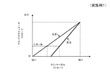
次に、本発明の実施例1に係るクラッチバイワイヤシステムの動作について具体例及び図面を用いて説明する。図3は、本発明の実施例1に係るクラッチバイワイヤシステムの第1例の動作を模式的に示したタイミングチャートである。図4は、本発明の実施例1に係るクラッチバイワイヤシステムの第2例の動作を模式的に示したタイミングチャートである。図5は、本発明の実施例1に係るクラッチバイワイヤシステムにおける高速時及び低速時のクラッチペダルストロークとクラッチアクチュエータストロークの関係を模式的に示したグラフである。図6は、本発明の実施例1に係るクラッチバイワイヤシステムにおける表示装置の変速時の表示の移り変わりを模式的に示したタイミングチャートである。図7は、本発明の実施例1に係るクラッチバイワイヤシステムにおける表示装置の変速をキャンセルした時の表示の移り変わりを模式的に示したタイミングチャートである。 Next, the operation of the clutch-by-wire system according to the first embodiment of the present invention will be described with reference to specific examples and drawings. FIG. 3 is a timing chart schematically showing the operation of the first example of the clutch-by-wire system according to the first embodiment of the present invention. FIG. 4 is a timing chart schematically showing the operation of the second example of the clutch-by-wire system according to the first embodiment of the present invention. FIG. 5 is a graph schematically showing the relationship between the clutch pedal stroke and the clutch actuator stroke at high speed and low speed in the clutch-by-wire system according to the first embodiment of the present invention. FIG. 6 is a timing chart schematically showing the display transition at the time of shifting of the display device in the clutch-by-wire system according to the first embodiment of the present invention. FIG. 7 is a timing chart schematically showing the display transition when the shift of the display device in the clutch-by-wire system according to the first embodiment of the present invention is cancelled.
図3を参照すると、制御モードが維持モードで、実シフトポジションが1速で、要求シフトポジションが1速で、クラッチが係合しているときに、シフトレバーを「+」に操作すると(図2のステップA2のYES)、要求シフトポジションが2速になるが(図2のステップA3)、この段階では制御モードが維持モードなので(図2のステップA6の維持モード)、ギヤ段が維持される(図2のステップA7)。その後、クラッチペダルを踏み込むと、踏み込み量に応じてクラッチアクチュエータがストロークするが(図2のステップA8)、踏み込みの初期では、実シフトポジションが1速で、要求シフトポジション2速で一致しない(図2のステップA9)。そして、踏み込みを増加させクラッチアクチュエータストロークがしきい値の断側になると(図2のステップA10のYES)、制御モードが変速モードになる(図2のステップA11)。変速モードになるとギヤチェンジを行うが(図2のステップA12)、変速中(現在のギヤの噛み合いが開放され、目標のギヤが噛み合うまでの間)にクラッチペダルの踏み込み量が少なくなった場合でも、図4のようにギヤが破損しない位置までクラッチアクチュエータストロークを断側に強制的にストロークさせる(図2のステップA13)。変速が終了し、実シフトポジションと要求シフトポジションが2速で一致すると(図2のステップA14のYES)、制御モードを維持モードに更新する(図2のステップA15)。 Referring to FIG. 3, when the control mode is the maintenance mode, the actual shift position is the first speed, the required shift position is the first speed, and the clutch is engaged, the shift lever is operated to “+” (FIG. 3). 2) (YES in step A2), the required shift position becomes the second speed (step A3 in FIG. 2), but since the control mode is the maintenance mode at this stage (maintenance mode in step A6 in FIG. 2), the gear stage is maintained. (Step A7 in FIG. 2). Thereafter, when the clutch pedal is depressed, the clutch actuator strokes according to the depression amount (step A8 in FIG. 2), but at the initial depression, the actual shift position is the first speed and the required shift position is not the same as the second shift position (FIG. 2 step A9). Then, when the depression is increased and the clutch actuator stroke becomes the threshold disengagement side (YES in step A10 in FIG. 2), the control mode becomes the shift mode (step A11 in FIG. 2). Even if the clutch pedal is depressed (during step A12 in FIG. 2), the amount of depression of the clutch pedal is reduced during the shift (until the current gear meshes and the target gear meshes). As shown in FIG. 4, the clutch actuator stroke is forcibly moved to the disengagement side until the gear is not damaged (step A13 in FIG. 2). When the shift is completed and the actual shift position matches the required shift position at the second speed (YES in step A14 in FIG. 2), the control mode is updated to the maintenance mode (step A15 in FIG. 2).
図5を参照すると、クラッチアクチュエータを制御する処理(図2のステップA8)では、変速制御装置(図1の50)は、車両の状態(エンジン制御装置(図1の60)からのエンジン回転数などの各部材の回転数、アクセルペダルセンサ(図1の12)からのアクセルペダルの踏み込み量、車速センサ(図示せず)からの車両速度、出力軸回転数センサ(図1の37)からの出力回転数など)に基づいて、低速時(所定値より低い車速のとき)はクラッチをコントロールしやすいようにクラッチペダル及びクラッチアクチュエータの各ストローク全幅を使用し、高速時(所定値以上の車速のとき)はキビキビした操作フィーリングを得るために、クラッチペダルのストロークを短くしている。 Referring to FIG. 5, in the process of controlling the clutch actuator (step A <b> 8 in FIG. 2), the speed change control device (50 in FIG. 1) determines the engine speed from the vehicle state (60 in FIG. 1). The number of rotations of each member, such as the amount of depression of the accelerator pedal from the accelerator pedal sensor (12 in FIG. 1), the vehicle speed from the vehicle speed sensor (not shown), and the output shaft rotation number sensor (37 in FIG. 1) Based on the output speed, etc., the full width of each stroke of the clutch pedal and clutch actuator is used at low speeds (when the vehicle speed is lower than a predetermined value) so that the clutch can be easily controlled. When) the stroke of the clutch pedal is shortened to get a crisp operation feeling.
図6を参照すると、実シフトポジションと要求シフトポジションが2速で一致している時(図2のステップA16のNO)、表示装置(図1の43)はギヤ位置「2速」で「点灯」する(図2のステップA18)。この後、シフトレバーを「+」に操作し(図2のステップA2のYES)、要求シフトポジションが3速になると(図2のステップA3)、実シフトポジションが2速で一致しないので(図2のステップA16のYES)、表示装置(図1の43)はギヤ位置「3速」で「点滅」する(図2のステップA17)。その後、クラッチペダルを踏み込んで変速を開始すると、実シフトポジションが変速中になるが、要求シフトポジションが3速で一致しないので(図2のステップA16のYES)、表示装置(図1の43)はギヤ位置「3速」で「点滅」したままである(図2のステップA17)。その後、変速が完了すると、実シフトポジションと要求シフトポジションが3速で一致し(図2のステップA16のNO)、表示装置(図1の43)はギヤ位置「3速」で「点灯」する(図2のステップA18)。これにより、シフトレバーを操作してから、クラッチを踏み込むまでの間は、ギヤ位置表示を点滅させることでドライバーに変速後のギヤを知らせることができる。 Referring to FIG. 6, when the actual shift position and the required shift position coincide with each other at the second speed (NO in step A16 in FIG. 2), the display device (43 in FIG. 1) is “lighted” at the gear position “second speed”. (Step A18 in FIG. 2). Thereafter, when the shift lever is operated to “+” (YES in step A2 in FIG. 2) and the required shift position becomes the third speed (step A3 in FIG. 2), the actual shift position does not coincide with the second speed (FIG. 2). 2 in step A16), the display device (43 in FIG. 1) “flashes” at the gear position “3rd speed” (step A17 in FIG. 2). After that, when shifting is started by depressing the clutch pedal, the actual shift position becomes shifting, but the required shift position does not coincide with the third speed (YES in step A16 in FIG. 2), so the display device (43 in FIG. 1). Remains “flashing” at the gear position “3rd speed” (step A17 in FIG. 2). Thereafter, when the shift is completed, the actual shift position and the requested shift position coincide with each other at the third speed (NO in step A16 in FIG. 2), and the display device (43 in FIG. 1) “lights” at the gear position “third speed”. (Step A18 in FIG. 2). As a result, during the period from when the shift lever is operated until the clutch is depressed, the gear position display can be blinked to inform the driver of the gear after the shift.
図7を参照すると、実シフトポジションと要求シフトポジションが2速で一致している時(図2のステップA16のNO)、表示装置(図1の43)はギヤ位置「2速」で「点灯」する(図2のステップA18)。この後、シフトレバーを「+」に操作し(図2のステップA2のYES)、要求シフトポジションが3速になると(図2のステップA3)、実シフトポジションが2速で一致しないので(図2のステップA16のYES)、表示装置(図1の43)はギヤ位置「3速」で「点滅」する(図2のステップA17)。その後、シフトレバーを「−」に操作し(図2のステップA4のYES)、要求シフトポジションが2速になると(図2のステップA5)、実シフトポジションと要求シフトポジションが2速で一致し(図2のステップA16のNO)、表示装置(図1の43)はギヤ位置「2速」で「点灯」する(図2のステップA18)。これにより、シフトレバーを「+」操作した後、「−」操作をすると、ギヤ位置表示の点滅が点灯に変化して、シフトチェンジがキャンセルされたことを、ドライバに知らせることができる。 Referring to FIG. 7, when the actual shift position coincides with the required shift position at the second speed (NO in step A16 in FIG. 2), the display device (43 in FIG. 1) is “lighted” at the gear position “second speed”. (Step A18 in FIG. 2). Thereafter, when the shift lever is operated to “+” (YES in step A2 in FIG. 2) and the required shift position becomes the third speed (step A3 in FIG. 2), the actual shift position does not coincide with the second speed (FIG. 2). 2), the display device (43 in FIG. 1) “flashes” at the gear position “3rd speed” (step A17 in FIG. 2). After that, the shift lever is operated to “−” (YES in step A4 in FIG. 2), and when the required shift position becomes the second speed (step A5 in FIG. 2), the actual shift position matches the required shift position at the second speed. (NO in step A16 in FIG. 2), the display device (43 in FIG. 1) “lights” at the gear position “second gear” (step A18 in FIG. 2). As a result, when the “−” operation is performed after the shift lever is operated “+”, the blinking of the gear position display changes to lighting, and the driver can be notified that the shift change is cancelled.
実施例1によれば、手動変速モードのときに自動クラッチ20が繋がったままの状態で自動変速機30を変速することを禁止できるため、自動変速機30の破損を防止でき、自動変速機30を保護することができる。また、実施例1によれば、手動変速モードのときに変速のタイミングを、クラッチペダルを踏み込むタイミングで決定できるため、変速の瞬間にハンドルを両手でしっかり握ることができ、走行安全性を向上させることができる。特に、コーナー手前の直進状態で事前に変速準備ができるため、コーナー直前から直後まで両手でハンドルを保持できる。例えば、カーブ手前で減速シフトダウンする際に、従来のマニュアルトランスミッション車両では、アクセルペダルからブレーキペダルに踏み変え、クラッチ断、シフトレバー操作、クラッチ係合、ブレーキからアクセルへの踏み変えの順に操作するが、実施例1では、あらかじめシフトレバーでシフトダウンを指示した後、ハンドルに両手を戻し、アクセルからブレーキに踏み変え、クラッチ断、クラッチ係合、ブレーキペダルからアクセルペダルへの踏み変えの順に操作すればよい。これにより、変速中にハンドルを両手で持ち、ブレーキ操作とクラッチ操作に集中することができる。
According to the first embodiment, since it is possible to prohibit shifting of the
また、実施例1によれば、変速中にクラッチペダルの踏み込み量が不足しても、変速中は少なくともクラッチアクチュエータストロークをしきい値に維持するか、もしくは、自動変速機30の変速を邪魔しないクラッチ断位置まで制御することで、自動変速機30を保護することができる。
Further, according to the first embodiment, even if the amount of depression of the clutch pedal is insufficient during the shift, at least the clutch actuator stroke is maintained at the threshold during the shift, or the shift of the
また、実施例1によれば、停車〜低速走行中は、丁寧なクラッチ操作がやりやすくなり、高速走行中は、キビキビ感のある変速がしやすくなる。例えば、低車速で走行中はショックの発生しないように丁寧なクラッチ操作に対応するため、ペダルストロークのコントロール領域を広く使えるように設定できる。また、高車速は多少乱暴なクラッチ操作をしてもショックが発生しないことから、クラッチ断に必要なクラッチペダルストロークを短く設定できる。また、高速時はクラッチを断した状態(駆動輪にトルクが伝わらない状態)をできるだけ短くしたい要望があるため、キビキビした変速が求められるが、このような要求を満たすことができる。 Further, according to the first embodiment, it is easy to perform a careful clutch operation during the stop to the low speed traveling, and it is easy to perform a speedy shift during the high speed traveling. For example, the pedal stroke control area can be set to be widely used in order to cope with a careful clutch operation so as not to generate a shock during traveling at a low vehicle speed. In addition, since a high vehicle speed does not cause a shock even if the clutch operation is somewhat rough, the clutch pedal stroke required for disengaging the clutch can be set short. Further, since there is a desire to shorten the clutch disengaged state (a state where torque is not transmitted to the drive wheels) as high as possible at high speeds, a sharp shift is required, but such a request can be satisfied.
さらに、実施例1によれば、実シフトポジションと要求シフトポジションが一致していないときにギヤ位置の表示を点滅させることで、ドライバは現在のギヤ位置と記録された変速指示のズレを認識できるため、ドライバがシフトレバーを操作し、変速を記録させたことを忘れて、クラッチペダルを踏んだときに不用意な変速が発生しないようにすることができる。 Further, according to the first embodiment, when the actual shift position and the requested shift position do not coincide with each other, the display of the gear position blinks so that the driver can recognize the shift of the current gear position and the recorded shift instruction. Therefore, it is possible to prevent an inadvertent shift from occurring when the driver forgets to record the shift by operating the shift lever and pressing the clutch pedal.
10 エンジン
11 フライホイール
12 アクセルペダルセンサ
20 自動クラッチ
21 摩擦クラッチ(クラッチ)
21a クラッチディスク
21b カバー
22 クラッチレバー
23 クラッチアクチュエータ
24 直流電動モータ
25 ロッド
26 ストロークセンサ
27 レリーズベアリング
28 ダイヤフラムスプリング
29 プレッシャプレート
30 自動変速機
31 入力軸
32 出力軸
33 入力軸回転数センサ
34、35、36 変速アクチュエータ
37 出力軸回転数センサ
41 クラッチペダルセンサ
42 シフトセンサ
43 表示装置
50 エンジン制御装置
60 変速制御装置
10
21a Clutch
Claims (10)
前記エンジンと前記クラッチを介して接続されるとともに、変速段の切り替えを操作するシフトアクチュエータを有する自動変速機と、
クラッチペダルの踏み込み量を検出するクラッチペダルセンサと、
シフトレバーの操作を検出するシフトセンサと、
自動変速モードのときに、自動的に前記クラッチアクチュエータと前記シフトアクチュエータの動作を制御し、手動変速モードのときに、少なくとも前記クラッチペダルセンサ及び前記シフトセンサからの信号に基づいて、前記クラッチアクチュエータと前記シフトアクチュエータの動作を制御する変速制御装置と、
を備えることを特徴とするクラッチバイワイヤシステム。 A clutch connected to the engine, and an automatic clutch having a clutch actuator for operating release and engagement of the clutch;
An automatic transmission having a shift actuator that is connected to the engine via the clutch and that operates to change gears;
A clutch pedal sensor for detecting the depression amount of the clutch pedal;
A shift sensor that detects the operation of the shift lever;
In the automatic shift mode, the clutch actuator and the shift actuator are automatically controlled. In the manual shift mode, the clutch actuator and the clutch actuator are controlled based on at least signals from the clutch pedal sensor and the shift sensor. A shift control device for controlling the operation of the shift actuator;
A clutch-by-wire system comprising:
前記変速制御装置は、前記手動変速モードのときに、前記しきい値に対応するクラッチペダルの踏み込み量を、前記センサからの前記車両の状態に応じて変化させるように制御することを特徴とする請求項1乃至3のいずれか一に記載のクラッチバイワイヤシステム。 A sensor for detecting the state of the vehicle,
The shift control device controls an amount of depression of a clutch pedal corresponding to the threshold value according to a state of the vehicle from the sensor in the manual shift mode. The clutch-by-wire system according to any one of claims 1 to 3.
前記変速制御装置は、前記手動変速モードのときに、前記シフトレバーの操作が記録された要求シフトポジションと、前記自動変速機の実際の実シフトポジションとにズレが生じているとき、前記表示装置にて前記要求シフトポジションと前記実シフトポジションにズレがあることを知らせるように表示させることを特徴とする請求項1乃至6のいずれか一に記載のクラッチバイワイヤシステム。 It has a display device that displays the gear position,
When the shift control device is in the manual shift mode, there is a shift between the required shift position where the operation of the shift lever is recorded and the actual actual shift position of the automatic transmission. The clutch-by-wire system according to any one of claims 1 to 6, wherein a display is made so as to notify that there is a difference between the required shift position and the actual shift position.
Priority Applications (2)
| Application Number | Priority Date | Filing Date | Title |
|---|---|---|---|
| JP2008063797A JP2009222068A (en) | 2008-03-13 | 2008-03-13 | Clutch-by-wire system |
| EP09003113A EP2101074A3 (en) | 2008-03-13 | 2009-03-04 | Clutch-by-wire system |
Applications Claiming Priority (1)
| Application Number | Priority Date | Filing Date | Title |
|---|---|---|---|
| JP2008063797A JP2009222068A (en) | 2008-03-13 | 2008-03-13 | Clutch-by-wire system |
Publications (1)
| Publication Number | Publication Date |
|---|---|
| JP2009222068A true JP2009222068A (en) | 2009-10-01 |
Family
ID=40756850
Family Applications (1)
| Application Number | Title | Priority Date | Filing Date |
|---|---|---|---|
| JP2008063797A Withdrawn JP2009222068A (en) | 2008-03-13 | 2008-03-13 | Clutch-by-wire system |
Country Status (2)
| Country | Link |
|---|---|
| EP (1) | EP2101074A3 (en) |
| JP (1) | JP2009222068A (en) |
Cited By (8)
| Publication number | Priority date | Publication date | Assignee | Title |
|---|---|---|---|---|
| US9096214B2 (en) | 2011-03-23 | 2015-08-04 | Aisin Seiki Kabushiki Kaisha | Gear shifting control device for hybrid vehicle |
| US9108636B2 (en) | 2011-03-25 | 2015-08-18 | Aisin Seiki Kabushiki Kaisha | Transmission control device for hybrid vehicle |
| JP2015148294A (en) * | 2014-02-07 | 2015-08-20 | トヨタ自動車株式会社 | Gear change control device |
| JP2017520445A (en) * | 2014-04-29 | 2017-07-27 | シェフラー テクノロジーズ アー・ゲー ウント コー. カー・ゲーSchaeffler Technologies AG & Co. KG | Device for simulating the force applied to the operating elements of a vehicle, preferably a pedal simulator, and a device for operating an electric clutch system |
| EP3312447A3 (en) * | 2016-10-18 | 2018-05-30 | Toyota Jidosha Kabushiki Kaisha | Clutch operating apparatus |
| DE102018117641A1 (en) | 2017-07-20 | 2019-01-24 | Toyota Jidosha Kabushiki Kaisha | Control device for a vehicle and control method for a vehicle |
| KR101956500B1 (en) | 2018-03-29 | 2019-06-24 | 주식회사평화발레오 | Device for generating nonlinear reaction force of vehicle's pedal |
| JP2021109532A (en) * | 2020-01-09 | 2021-08-02 | いすゞ自動車株式会社 | Control apparatus, and control method |
Families Citing this family (10)
| Publication number | Priority date | Publication date | Assignee | Title |
|---|---|---|---|---|
| CN103527761B (en) * | 2013-10-29 | 2016-02-03 | 长城汽车股份有限公司 | The controlling method of the transmission assembly of auto-manual |
| FR3019124A1 (en) * | 2014-04-01 | 2015-10-02 | Peugeot Citroen Automobiles Sa | DEVICE FOR CONTROLLING THE CLUTCH OF A VEHICLE BY DIRECT HYDRAULIC LINK COUPLED WITH TWO CLUTCH EMITTERS |
| EP2998604B1 (en) * | 2014-09-19 | 2020-01-15 | KNORR-BREMSE Systeme für Nutzfahrzeuge GmbH | System and method for controlling a clutch |
| FR3027079B1 (en) * | 2014-10-13 | 2018-03-02 | Valeo Embrayages | METHOD AND SYSTEM FOR CONTROLLING A CLUTCH |
| DE102014017175B4 (en) * | 2014-11-20 | 2016-11-10 | Audi Ag | Method and device for operating a motor vehicle |
| SE539280C2 (en) | 2015-06-16 | 2017-06-13 | Scania Cv Ab | Clutch by wire system with indication unit |
| US10793133B2 (en) | 2016-07-01 | 2020-10-06 | Borgwarner Inc. | Valve assembly and system including same for controlling fluid flow to and from a clutch |
| CN107878191A (en) * | 2017-12-18 | 2018-04-06 | 高稳根 | One kind is used for manual automobile short stroke clutch, and intelligently auxiliary tramples device |
| JP2020041554A (en) * | 2018-09-06 | 2020-03-19 | トヨタ自動車株式会社 | Vehicle control device |
| FR3091321B1 (en) * | 2018-12-30 | 2021-07-16 | Valeo Embrayages | Method for controlling a clutch and control unit for a clutch capable of implementing such a method |
Family Cites Families (6)
| Publication number | Priority date | Publication date | Assignee | Title |
|---|---|---|---|---|
| JPS58184345A (en) * | 1982-04-23 | 1983-10-27 | Toyota Motor Corp | Speed change gear for car |
| JPS59226738A (en) * | 1983-06-03 | 1984-12-19 | Toyota Motor Corp | Controlling apparatus for driving by change of gear ratio of auxiliary transmission |
| JP2001260693A (en) * | 2000-03-21 | 2001-09-26 | Isuzu Motors Ltd | Controller for selective clutch |
| FR2826700B1 (en) * | 2001-05-09 | 2003-09-26 | Valeo | METHOD FOR CONTROLLING A CLUTCH IN A MOTOR VEHICLE |
| JP2005214370A (en) | 2004-02-02 | 2005-08-11 | Nissan Motor Co Ltd | Control device of vehicular power train |
| FR2900999B1 (en) * | 2006-05-12 | 2009-02-20 | Renault Sas | METHOD FOR AIDING THE SYNCHRONIZATION OF A CLUTCH |
-
2008
- 2008-03-13 JP JP2008063797A patent/JP2009222068A/en not_active Withdrawn
-
2009
- 2009-03-04 EP EP09003113A patent/EP2101074A3/en not_active Withdrawn
Cited By (10)
| Publication number | Priority date | Publication date | Assignee | Title |
|---|---|---|---|---|
| US9096214B2 (en) | 2011-03-23 | 2015-08-04 | Aisin Seiki Kabushiki Kaisha | Gear shifting control device for hybrid vehicle |
| US9108636B2 (en) | 2011-03-25 | 2015-08-18 | Aisin Seiki Kabushiki Kaisha | Transmission control device for hybrid vehicle |
| JP2015148294A (en) * | 2014-02-07 | 2015-08-20 | トヨタ自動車株式会社 | Gear change control device |
| JP2017520445A (en) * | 2014-04-29 | 2017-07-27 | シェフラー テクノロジーズ アー・ゲー ウント コー. カー・ゲーSchaeffler Technologies AG & Co. KG | Device for simulating the force applied to the operating elements of a vehicle, preferably a pedal simulator, and a device for operating an electric clutch system |
| EP3312447A3 (en) * | 2016-10-18 | 2018-05-30 | Toyota Jidosha Kabushiki Kaisha | Clutch operating apparatus |
| RU2667797C1 (en) * | 2016-10-18 | 2018-09-24 | Тойота Дзидося Кабусики Кайся | Clutch control device |
| DE102018117641A1 (en) | 2017-07-20 | 2019-01-24 | Toyota Jidosha Kabushiki Kaisha | Control device for a vehicle and control method for a vehicle |
| CN109282032A (en) * | 2017-07-20 | 2019-01-29 | 丰田自动车株式会社 | Control device for vehicle and the control method for vehicle |
| KR101956500B1 (en) | 2018-03-29 | 2019-06-24 | 주식회사평화발레오 | Device for generating nonlinear reaction force of vehicle's pedal |
| JP2021109532A (en) * | 2020-01-09 | 2021-08-02 | いすゞ自動車株式会社 | Control apparatus, and control method |
Also Published As
| Publication number | Publication date |
|---|---|
| EP2101074A3 (en) | 2009-10-28 |
| EP2101074A2 (en) | 2009-09-16 |
Similar Documents
| Publication | Publication Date | Title |
|---|---|---|
| JP2009222068A (en) | Clutch-by-wire system | |
| JP6071170B2 (en) | Vehicle operation method | |
| JP2010270804A (en) | Clutch-by-wire system | |
| JP5822615B2 (en) | Automatic clutch control device and shift control method thereof | |
| JP4561587B2 (en) | Shift control device | |
| JP4591711B2 (en) | Method for operating a drive transmission system of an automobile | |
| JP5939317B2 (en) | Control device for hybrid vehicle | |
| JP3675341B2 (en) | Vehicle drive device | |
| US20160176405A1 (en) | Transmission | |
| EP2481948A1 (en) | Shift device for vehicle | |
| JPWO2018051593A1 (en) | Automatic transmission and control method thereof | |
| JP6098530B2 (en) | Clutch control device | |
| JP5275262B2 (en) | Control device and control method for automatic transmission | |
| CN107269835B (en) | Shift control device for hybrid vehicle | |
| JP5856778B2 (en) | Power transmission control device | |
| JP5835573B2 (en) | Automatic transmission clutch control device | |
| JP2007211945A (en) | Shift control device for vehicle | |
| JP4371269B2 (en) | Control device and control method for automatic transmission | |
| JP6213276B2 (en) | Shift control device | |
| JP4634746B2 (en) | Vehicle speed change control device | |
| JP2014109359A (en) | Vehicle driving device | |
| JP4881642B2 (en) | Vehicle shift control device | |
| FR2942178A1 (en) | Torque transmitting device for motor vehicle i.e. rally car, has logic unit receiving output signal delivered by sensor and controlling motor in proper direction to select active configuration of gearbox corresponding to lever actuation | |
| JP4845297B2 (en) | Automatic transmission | |
| JP4818543B2 (en) | Clutch control device |
Legal Events
| Date | Code | Title | Description |
|---|---|---|---|
| A300 | Withdrawal of application because of no request for examination |
Free format text: JAPANESE INTERMEDIATE CODE: A300 Effective date: 20110607 |