JP2009208559A - Collision prevention assistant device - Google Patents
Collision prevention assistant device Download PDFInfo
- Publication number
- JP2009208559A JP2009208559A JP2008052302A JP2008052302A JP2009208559A JP 2009208559 A JP2009208559 A JP 2009208559A JP 2008052302 A JP2008052302 A JP 2008052302A JP 2008052302 A JP2008052302 A JP 2008052302A JP 2009208559 A JP2009208559 A JP 2009208559A
- Authority
- JP
- Japan
- Prior art keywords
- ecu
- automatic brake
- value
- driver
- collision
- Prior art date
- Legal status (The legal status is an assumption and is not a legal conclusion. Google has not performed a legal analysis and makes no representation as to the accuracy of the status listed.)
- Pending
Links
Images


Landscapes
- Steering Controls (AREA)
- Regulating Braking Force (AREA)
Abstract
Description
本発明は衝突防止支援装置に関し、より特定的には、車両が障害物に衝突する危険性がある場合に自動で制動動作を実行する衝突防止支援装置に関する。 The present invention relates to a collision prevention support device, and more particularly to a collision prevention support device that automatically performs a braking operation when there is a risk that a vehicle will collide with an obstacle.
従来、車両の周囲の障害物を検知し、車両と障害物とが衝突する可能性がある場合に、運転者の操作に依らない自動的なブレーキ動作(以下、自動ブレーキと呼称する)を開始する衝突防止支援装置が開発されている。 Conventionally, when an obstacle around the vehicle is detected and there is a possibility of collision between the vehicle and the obstacle, automatic braking operation (hereinafter referred to as automatic braking) that does not depend on the driver's operation is started. A collision prevention support device has been developed.
例えば、特許文献1に開示される車両用衝突防止支援装置は、障害物を検知すると、車両と障害物との衝突をブレーキにより回避するために最低限必要な距離(以下、制動限界距離と呼称する)、および車両と障害物との衝突を操舵により回避するために最低限必要な距離(以下、操舵限界距離と呼称する)を算出する。図12は相対速度と制動限界距離および操舵限界距離との関係を示すグラフである。図12に示すように、制動限界距離および操舵限界距離は車両と障害物との相対速度の大きさに応じて変化する。衝突防止支援装置は、操舵限界距離が制動限界距離以下である場合(図12においては相対速度がV1以上である場合)に以下の制御を行う。
For example, when a vehicle collision prevention support apparatus disclosed in
まず、衝突防止支援装置は、車両と障害物との距離(以下、衝突距離と呼称する)が第1の所定値よりも小さい場合に警報を発する。そして、警報を発した時点以後に運転者による操舵操作がない場合、衝突防止支援装置は、衝突距離が制動限界距離以下になった時点で制動装置を動作させる。一方、警報を発した時点以後に運転者による操舵操作があった場合、衝突防止支援装置は、衝突距離が操舵限界距離以下になった時点で自動ブレーキを開始する。
上記従来の衝突防止支援装置によると、運転者が操舵による衝突回避を企てつつ、意図的に操舵操作を実施していない場合であっても、操舵限界距離が制動限界距離以下で、且つ衝突距離が制動限界距離以下になった時点で自動ブレーキが開始されてしまう。このように、運転者が操舵による回避を企てている場合に、運転者が望まないタイミングで自動ブレーキが開始されると、運転者は、煩わしさを感じたり、衝突回避のための操舵操作を思うように実行できなくなったりする問題が生じる。 According to the conventional collision prevention support device, the steering limit distance is equal to or less than the braking limit distance even when the driver attempts to avoid the collision by steering and does not intentionally perform the steering operation. Automatic braking is started when the distance becomes less than the braking limit distance. In this way, when the driver is trying to avoid by steering, if the automatic braking is started at a timing that the driver does not want, the driver feels bothered or the steering operation for collision avoidance. The problem of being unable to execute as expected.
本発明は、上記の課題を鑑みてなされたものであり、最適なタイミングで自動ブレーキを開始する衝突防止支援装置を提供することを目的とする。 The present invention has been made in view of the above problems, and an object of the present invention is to provide a collision prevention support device that starts automatic braking at an optimal timing.
本発明は、上記の課題を解決するために、以下の構成を採用した。すなわち、第1の発明は、車両の周囲に存在する障害物と車両との衝突を予測する衝突予測手段と、運転者が把持するステアリングホイールのリム部の把持状態を検出する把持状態検出手段と、障害物と車両とが衝突すると予測された場合、運転者の操作に依らない自動的な制動動作を開始する自動ブレーキタイミングを把持状態検出手段により検出された把持状態に応じて決定する自動ブレーキタイミング決定手段と、自動ブレーキタイミング決定手段により決定された自動ブレーキタイミングで制動動作を実行する制動手段とを備える衝突防止支援装置である。 The present invention employs the following configuration in order to solve the above problems. That is, the first invention includes a collision prediction unit that predicts a collision between an obstacle existing around the vehicle and the vehicle, and a gripping state detection unit that detects a gripping state of the rim portion of the steering wheel gripped by the driver. When the vehicle is predicted to collide with an obstacle, the automatic brake determines the automatic brake timing for starting the automatic braking operation not depending on the operation of the driver according to the gripping state detected by the gripping state detecting means. A collision prevention assisting device including a timing determining unit and a braking unit that executes a braking operation at an automatic brake timing determined by the automatic brake timing determining unit.
第2の発明は、第1の発明において、把持状態検出手段は、運転者がステアリングホイールのリム部を把持する把持位置を検出する把持位置検出手段を含み、自動ブレーキタイミング決定手段は、把持位置に応じて自動ブレーキタイミングを決定する。 In a second aspect based on the first aspect, the gripping state detecting means includes gripping position detecting means for detecting a gripping position at which the driver grips the rim portion of the steering wheel, and the automatic brake timing determining means is the gripping position. The automatic brake timing is determined according to
第3の発明は、第2の発明において、把持位置検出手段は、ステアリングホイールのリム部の外表面に配置されたタッチセンサへのタッチ入力に基づいて把持位置を検出する。 In a third aspect based on the second aspect, the gripping position detecting means detects the gripping position based on a touch input to a touch sensor disposed on the outer surface of the rim portion of the steering wheel.
第4の発明は、第3の発明において、タッチセンサは、ステアリングホイールのリム部の外表面に、リム部の円周方向に沿って複数配置される。 In a fourth aspect based on the third aspect, a plurality of touch sensors are arranged on the outer surface of the rim portion of the steering wheel along the circumferential direction of the rim portion.
第5の発明は、第2の発明において、把持位置検出手段は、ステアリングホイールのリム部および当該リム部を把持する運転者の手を含む画像を撮影する撮像装置を含み、画像をもとに把持位置を検出する。 According to a fifth invention, in the second invention, the gripping position detecting means includes an imaging device that captures an image including a rim portion of the steering wheel and a driver's hand gripping the rim portion. The grip position is detected.
第6の発明は、第2の発明において、衝突防止支援装置は、ステアリングホイールの舵角を検出する舵角検出手段をさらに備え、自動ブレーキタイミング決定手段は、舵角および把持位置に応じて自動ブレーキタイミングを決定する。 In a sixth aspect based on the second aspect, the collision prevention assisting device further includes a rudder angle detecting means for detecting a rudder angle of the steering wheel, and the automatic brake timing determining means is automatically activated according to the rudder angle and the gripping position. Determine the brake timing.
第7の発明は、第1の発明において、衝突防止支援装置は、障害物と車両とが衝突すると予測された場合、自動ブレーキタイミングより早いタイミングで警報装置を動作させる警報制御手段をさらに備え、把持状態検出手段は、把持位置の変化を検出する把持位置変化検出手段を含み、自動ブレーキタイミング決定手段は、警報装置が動作する前後で把持位置の変化が検出された場合、把持位置の変化が検出されない場合に比べて自動ブレーキタイミングを相対的に遅くする。 In a seventh aspect based on the first aspect, the collision prevention assisting device further includes alarm control means for operating the alarm device at a timing earlier than the automatic brake timing when the obstacle and the vehicle are predicted to collide, The gripping state detecting means includes a gripping position change detecting means for detecting a change in the gripping position, and the automatic brake timing determining means detects the change in the gripping position when a change in the gripping position is detected before and after the alarm device operates. The automatic brake timing is relatively delayed as compared with the case where it is not detected.
第8の発明は、第1の発明において、把持状態検出手段は、運転者がリム部を片手で把持しているか、あるいは両手で把持しているかを判定する把持手判定手段を含み、自動ブレーキタイミング決定手段は、運転者がリム部を片手で把持している場合、リム部を両手で把持している場合に比べて自動ブレーキタイミングを相対的に早くする。 In an eighth aspect based on the first aspect, the gripping state detecting means includes gripping hand determining means for determining whether the driver is gripping the rim portion with one hand or both hands, and the automatic brake The timing determination means makes the automatic brake timing relatively earlier when the driver is holding the rim portion with one hand than when the driver is holding the rim portion with both hands.
第1の発明によれば、運転者が操舵操作による衝突回避を企てている場合に不要な自動ブレーキが実行されることがなく、運転者は、操舵操作によって車両と障害物との衝突をより安全に回避することができる。 According to the first aspect of the present invention, unnecessary automatic braking is not executed when the driver intends to avoid collision by a steering operation, and the driver can make a collision between the vehicle and an obstacle by the steering operation. It can be avoided more safely.
第2の発明によれば、例えば、運転者がステアリングホイールのリム部を操舵し難い位置で把持している場合、相対的に早いタイミングで自動ブレーキが実行されて、運転者は、安全に操舵操作による車両と障害物との衝突回避を行うことができる。また、運転者がステアリングホイールのリム部を操舵し易い位置で把持している場合、相対的に遅いタイミングで自動ブレーキが実行され、不要な自動ブレーキの実行を抑制することができる。 According to the second invention, for example, when the driver holds the rim portion of the steering wheel at a position where it is difficult to steer, automatic braking is executed at a relatively early timing, and the driver can safely steer. The collision between the vehicle and the obstacle can be avoided by the operation. In addition, when the driver holds the rim portion of the steering wheel at a position where the driver can easily steer, automatic braking is executed at a relatively late timing, and execution of unnecessary automatic braking can be suppressed.
第3の発明によれば、運転者が操舵装置を把持するだけで、運転者が把持するステアリングホイールのリム部の把持位置を検出することができる。 According to the third invention, the grip position of the rim portion of the steering wheel gripped by the driver can be detected only by the driver gripping the steering device.
第4の発明によれば、ステアリングホイールのリム部の把持位置を、より詳細に判別することができる。 According to the fourth aspect, the grip position of the rim portion of the steering wheel can be determined in more detail.
第5の発明によれば、把持位置を検出する機器としてカメラなどの撮像機器を用い、該カメラで撮影される画像をもとに非接触で運転者が把持するステアリングホイールのリム部の把持位置を検出することができる。そのため、把持位置を検出する機器としてタッチセンサなどの接触式の検出機器を用いる場合に比べ、当該機器が消耗し難い。 According to the fifth aspect, the gripping position of the rim portion of the steering wheel that is gripped by the driver in a non-contact manner based on an image captured by the camera using an imaging device such as a camera as the device that detects the gripping position. Can be detected. Therefore, compared with the case where a contact-type detection device such as a touch sensor is used as a device for detecting the grip position, the device is less likely to be consumed.
第6の発明によれば、運転者が操作し易い把持位置が舵角に応じて変化しても、舵角および把持位置に応じて自動ブレーキタイミングが決定されるため、最適なタイミングで自動ブレーキを作動させることができる。 According to the sixth invention, even if the gripping position that is easy for the driver to operate is changed according to the steering angle, the automatic brake timing is determined according to the steering angle and the gripping position. Can be activated.
第7の発明によれば、運転者が警報により衝突の危険を認識してステアリングホイールのリム部の把持位置を変更した場合には、運転者にとって不要な自動ブレーキの作動を抑制することができる。 According to the seventh aspect of the invention, when the driver recognizes the danger of collision by an alarm and changes the grip position of the rim portion of the steering wheel, the operation of the automatic brake unnecessary for the driver can be suppressed. .
第8の発明によれば、運転者がステアリングホイールのリム部を片手で把持しており、操舵し難い状態である場合、自動的な制動動作が実行されるタイミングが早くなるため、運転者は、安全に衝突回避のための操舵操作を行うことができる。 According to the eighth invention, when the driver holds the rim portion of the steering wheel with one hand and is difficult to steer, the timing for executing the automatic braking operation is earlier, Steering operation for avoiding collision can be performed safely.
(第1の実施形態)
以下、図1から図6を参照して、本発明の第1の実施形態に係る衝突防止支援装置について説明する。第1の実施形態に係る衝突防止支援装置は、該装置を搭載した車両が障害物等へ接近した場合、運転者がステアリングホイールを把持する位置(以下把持位置と呼称する)に応じて、自動ブレーキタイミングを変更する。操舵操作による衝突回避の難易度は、把持位置に応じて異なる。そのため、把持位置に応じて自動ブレーキタイミングを変更することで、運転者は、より安全に操舵操作により車両と障害物との衝突を回避することができる。
(First embodiment)
Hereinafter, with reference to FIG. 1 to FIG. 6, a collision prevention support apparatus according to a first embodiment of the present invention will be described. The collision prevention assisting apparatus according to the first embodiment is automatically operated according to a position where the driver grips the steering wheel (hereinafter referred to as a gripping position) when a vehicle equipped with the apparatus approaches an obstacle or the like. Change the brake timing. The difficulty level of collision avoidance by the steering operation varies depending on the gripping position. Therefore, by changing the automatic brake timing according to the gripping position, the driver can more safely avoid the collision between the vehicle and the obstacle by the steering operation.
まず、図1を参照して衝突防止支援装置の機能構成の一例について説明する。なお、図1は、衝突防止支援装置の機能構成の一例を示すブロック図である。図1に示すように、衝突防止支援装置は、ミリ波レーダー11、タッチセンサ121、タッチセンサ122、ECU(Electrical Control Unit)13、およびブレーキ制御装置14を備える。
First, an example of a functional configuration of the collision prevention support apparatus will be described with reference to FIG. FIG. 1 is a block diagram illustrating an example of a functional configuration of the collision prevention support apparatus. As shown in FIG. 1, the collision prevention support device includes a
ミリ波レーダー11は、車外監視用のセンサとして、車両のフロントグリル等の構造材に配置される。ミリ波レーダー11は、ミリ波長の電磁波を放射し、車両周囲に存在する障害物からの反射波を受信して、該障害物を検出する。さらに、ミリ波レーダー11は、検出した車両から障害物までの距離L、および該障害物に対する車両の相対速度Vを測定する。ミリ波レーダー11は障害物を検出すると、距離L、および相対速度Vを測定し、各測定値を示す信号をECU13へ出力する。なお、距離Lおよび相対速度Vを測定可能であれば、ミリ波レーダー11の代わりに、レーザーセンサなどの他の計測器を用いても構わない。
The
タッチセンサ121およびタッチセンサ122は、衝突防止支援装置が搭載される車両のステアリングホイールのリム部表面に各々配置される。本実施形態において、ステアリングホイールは略円環状に構成される。タッチセンサ121およびタッチセンサ122は、図2に示すようにステアリングホイールのリム部表面を覆うように配置される。なお、図2はタッチセンサが配置されたステアリングホイールの一例を示す外観図である。図2に示すように、タッチセンサ121はステアリングホイールが回転していない状態でリム部上側に配置される。また、タッチセンサ122はステアリングホイールが回転していない状態でリム部下側に配置される。このように、ステアリングホイールのリム部の表面は、タッチセンサ121およびタッチセンサ122の何れかにより覆われた状態となる。したがって、運転者は、車両を操舵するためリム部を握ると、自ずとタッチセンサ121および/またはタッチセンサ122へタッチ入力することになる。以下では、各タッチセンサがタッチ入力を受けている状態をオン状態、タッチ入力を受けていない状態をオフ状態と呼称する。そして、タッチセンサ121およびタッチセンサ122は、オン状態であるかオフ状態であるかを示す信号(以下、タッチ入力情報と呼称する)をECU13へ出力する。なお、タッチセンサ121およびタッチセンサ122には、静電式、感圧式など、種々の方式のタッチセンサを用いることができる。
The
図1の説明に戻り、ECU13は、典型的にはマイクロコンピュータなどの情報処理装置、メモリなどの記憶装置、およびインターフェース回路などを備える処理装置である。ECU13は、ミリ波レーダーから出力される距離Lおよび相対速度Vに基づいて、障害物と車両とが衝突するまでの衝突予想時間TTCを算出する。また、ECU13は、タッチセンサ121およびタッチセンサ122から出力されるタッチ入力情報に基づいて衝突予想時間TTCの閾値THを算出する。そして、ECU13は、時間TTCの値が閾値THに達した場合、自動ブレーキを開始する指示をブレーキ制御装置14へ出力する。したがって、閾値THの値が大きいほど、車両と障害物とが衝突すると予想される時点から自動ブレーキが開始される時点までの時間が長くなる。すなわち、閾値THの値が相対的に大きいほど、相対的に早い時点で自動ブレーキが開始される。
Returning to the description of FIG. 1, the
ブレーキ制御装置14は、車両に備えられたブレーキの動作を制御する装置である。ブレーキ制御装置14は、ECU13から出力される指示信号に基づいて自動ブレーキを実行する。
The
次に、図3を参照して、ECU13の処理について詳細に説明する。図3はECU13によって実行される処理の一例を示すフローチャートである。
Next, the processing of the
ステップS11において、ECU13は、イグニッションスイッチがONであるか否かを判定する。ECU13は、イグニッションスイッチがONであると判断した場合、処理をステップS12へ進める。一方、イグニッションスイッチがON以外の状態(例えばアクセサリー電源がオンの状態やイグニッションスイッチがOFFになっている状態)であると判断した場合、ECU13は、処理を終了する。ステップS11の処理によって、イグニッションスイッチがONである間、以下に説明するステップS12からステップS20までの処理が繰り返される。
In step S11, the
ステップS12において、ECU13は、衝突予想時間TTCを算出する。具体的には、ECU13は、衝突予想時間TTCの値をミリ波レーダー11から出力される距離Lおよび相対速度Vに基づいて下式で算出する。
TTC=L/V
ECU13は算出した衝突予想時間TTCの値を記憶装置に記憶する。ECU13は、ステップS12の処理を完了すると、処理をステップS13へ進める。
In step S12, the
TTC = L / V
The
ステップS13において、ECU13は、操舵限界時間TSを算出する。操舵限界時間TSとは、車両と障害物との衝突を操舵により回避するために最低限必要な時間である。具体的には、ECU13は相対速度Vおよび操舵限界時間算出テーブルにもとづいて操舵限界時間TSを算出する。操舵限界時間算出テーブルは、操舵限界時間TSと相対速度Vとの関係を示すデータテーブルであり、ECU13が備える記憶装置に予め記憶される。なお、図4は操舵限界時間算出テーブルの一例を示す図である。以下、図4を参照して、ECU13が操舵限界時間TSの値を算出する方法について説明する。
In step S13, the
図4に示す操舵限界時間算出テーブルでは、1列目に相対速度Vが示され、相対速度Vの各値に対応した操舵限界時間TSの各値が同行の2列目に示される。ECU13は、ミリ波レーダー11から取得した相対速度Vの値を示す行を操舵限界時間算出テーブル上で検索して、当該行に記載された操舵限界時間TSの値を取得する。
In the steering limit time calculation table shown in FIG. 4, the relative speed V is shown in the first column, and each value of the steering limit time TS corresponding to each value of the relative speed V is shown in the second column of the same row. The
例えば、相対速度Vの値が30Km/hであった場合、ECU13は、図4に示す操舵限界時間算出テーブルにもとづいて、操舵限界時間TSの値として10secを取得する。
For example, when the value of the relative speed V is 30 Km / h, the
なお、図4に示す操舵限界時間算出テーブルは一例であり、該テーブルにおいて設定される相対速度Vおよび操舵限界時間TSの値は上記に限らない。また、上記では操舵限界時間TSがデータテーブルから算出される例を示したが、操舵限界時間TSの導出方法は上記に限らない。例えば、操舵限界時間TSは、操舵限界時間TSと相対速度Vとの関係を示す数式などに基づいて算出されても良い。 Note that the steering limit time calculation table shown in FIG. 4 is an example, and the values of the relative speed V and the steering limit time TS set in the table are not limited to the above. In the above description, the steering limit time TS is calculated from the data table. However, the method for deriving the steering limit time TS is not limited to the above. For example, the steering limit time TS may be calculated based on a mathematical formula indicating the relationship between the steering limit time TS and the relative speed V.
ECU13は算出した操舵限界時間TSの値を記憶装置に記憶する。ECU13は、ステップS13の処理を完了すると、処理をステップS14へ進める。
The
ステップS14において、ECU13は、制動限界時間TBを算出する。制動限界時間TBとは、車両と障害物との衝突をブレーキにより回避するために最低限必要な時間である。具体的には、ECU13は、相対速度Vおよび制動限界時間算出テーブル(図示せず)にもとづいて制動限界時間TBを算出する。制動限界時間算出テーブルは、制動限界時間TBと相対速度Vとの関係を示すデータテーブルであり、ECU13が備える記憶装置に予め記憶される。制動限界時間算出テーブルでは、相対速度Vの各値に対応した制動限界時間TBの値が示される。ECU13は、ミリ波レーダー11から取得した相対速度Vの値を制動限界時間算出テーブル上で検索して、相対速度Vの値に対応する制動限界時間TBの値を取得する。ECU13は算出した制動限界時間TBの値を記憶装置に記憶する。ECU13は、ステップS14の処理を完了すると、処理をステップS15へ進める。
In step S14, the
ステップS15において、ECU13は、操舵限界時間TSの値が制動限界時間TBの値より小さいか否かを判定する。具体的には、ECU13は、記憶装置に記憶した操舵限界時間TSおよび制動限界時間TBの値を読み出し、大小を比較する。ECU13は、操舵限界時間TSの値が制動限界時間TBの値より小さいと判断した場合、処理をステップS16へ進める。一方、ECU13は、操舵限界時間TSの値が制動限界時間TBの値以上であると判断した場合、処理をステップS18へ進める。
In step S15, the
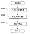
ステップS16において、ECU13は、閾値THを算出する。具体的には、ECU13は、把持位置に応じて、早出し時間αの値を算出する。そして、ECU13は、操舵限界時間TSに早出し時間αの値を加算して閾値THの値を算出する。なお、早出し時間αとは、タッチセンサの入力情報にもとづいて決定される数値である。以下、図5を参照してステップS16において実行されるサブルーチン処理の詳細について説明する。なお、図5は、図3に示すステップS16のサブルーチン処理の一例を示すフローチャートである。
In step S16, the
ステップS161において、ECU13は、各タッチセンサ121および122から出力されるタッチ入力情報を取得する。具体的には、ECU13は、各タッチセンサ121および122がオン状態であるかオフ状態であるかを示す信号をタッチセンサ121およびタッチセンサ122から取得し、各タッチセンサ121および122への入力状態を記憶装置に記憶する。ECU13はステップS161の処理を完了すると処理をステップS162へ進める。
In step S161, the
ステップS162において、ECU13は、早出し時間αを算出する。具体的には、ECU13は、ステップS161において取得したタッチ入力情報、および予め記憶装置に記憶された図6に示す早出し時間算出テーブルに基づいて早出し時間αを算出する。早出し時間算出テーブルとは、タッチ入力情報と早出し時間αの値との関係を示すデータテーブルである。なお、図6は早出し時間算出テーブルの一例を示す図である。以下、図6を参照して、ECU13が早出し時間αの値を算出する方法について説明する。
In step S162, the
図6に示す早出し時間算出テーブルでは、1列目にタッチセンサ121への入力状態(オン状態またはオフ状態)が示される。同様に、2列目にタッチセンサ122への入力状態が示される。そして、各行の1列目および2列目に示された各タッチセンサ121および122の入力状態の組み合わせに応じた早出し時間αの値が同行の3列目に示される。ECU13は、ステップS161で記憶したタッチ入力情報に合致する各タッチセンサ121および122の入力状態の組み合わせを示す行を早出し時間算出テーブル上で検索して、当該行に示された早出し時間αの値を取得する。
In the quick-start time calculation table shown in FIG. 6, the input state (on state or off state) to the
早出し時間算出テーブル上において設定される早出し時間αの値は、操舵の難易度に応じて設定されることが望ましい。具体的には、各タッチセンサ121および122のタッチ入力情報の組み合わせ、すなわち把持位置にもとづいて操舵の難易度を推定し、推定した難易度に応じて早出し時間αの値を設定すると良い。例えば、図6において、タッチセンサ121がオン状態である場合、すなわち運転者がステアリングホイールの上部を把持している場合(図2参照)、運転者は、操舵により衝突を十分回避可能であると考えられる。このような場合、自動ブレーキタイミングを必要以上に早くしないよう早出し時間αの値は相対的に小さい値に設定されることが望ましい。したがって、図6に示す早出し時間算出テーブルにおいて、タッチセンサ121がオン状態である場合、早出し時間αの値を0とする。
It is desirable that the value of the quick pick-up time α set on the quick pick-up time calculation table is set according to the steering difficulty level. Specifically, the steering difficulty level is estimated based on the combination of touch input information of the
一方、タッチセンサ121がオフ状態で、且つタッチセンサ122がオン状態である場合、すなわち運転者がステアリングホイールの下部のみを把持している場合、操舵による衝突回避が困難であると考えられる。このような場合、運転者がステアリングホイールの上部を把持している場合に比べ、早出し時間αの値が大きな値で設定されることが望ましい。したがって、図6に示す早出し時間算出テーブルでは、タッチセンサ121がオフ状態で、且つタッチセンサ122がオン状態である場合、早出し時間αの値は0より大きいα1とする。また、タッチセンサ121およびタッチセンサ122の何れもオフ状態である場合、運転者はステアリングホイールを把持していないため、ステアリングホイールの下部を把持している場合よりも、操舵による衝突回避がさらに困難で危険な状態であると考えられる。したがって、図6に示す早出し時間算出テーブルでは、タッチセンサ121およびタッチセンサ122の何れもオフ状態である場合、早出し時間αの値はα1よりも大きな値α2とする。
On the other hand, when the
このように、タッチ入力情報の組み合わせから把持位置を検出することができる。また、上記の説明のようにして早出し時間αの値が設定されると、運転者による操舵操作が困難な状況では早い時点で自動ブレーキが開始され、運転者は衝突を回避し易くなる。なお、図6に示す早出し時間算出テーブルは一例であり、該テーブルにおいて設定される早出し時間αの値は上記に限らない。 In this way, the grip position can be detected from the combination of touch input information. In addition, when the value of the quick start time α is set as described above, automatic braking is started at an early point in a situation where a steering operation by the driver is difficult, and the driver can easily avoid a collision. Note that the early search time calculation table shown in FIG. 6 is an example, and the value of the quick search time α set in the table is not limited to the above.
図5の説明に戻り、ECU13は、ステップS162の処理を完了すると、処理をステップS163へ進める。
Returning to the description of FIG. 5, when the
ステップS163において、ECU13は閾値THの値を算出する。具体的には、ECU13は、記憶装置から操舵限界時間TSの値および早出し時間αの値を読み出す。そして、ECU13は、下式のように操舵限界時間TSに早出し時間αの値を加算して閾値THを算出する。
TH=TS+α
ECU13は、算出した閾値THの値を記憶装置に記憶する。ECU13はステップS163の処理を完了すると、図3に示すフローチャートの処理に戻り、処理をステップS17へ進める。
In step S163, the
TH = TS + α
The
上記に説明したステップS16のサブルーチン処理により、把持位置を示すタッチ入力情報の組み合わせに応じて早出し時間αの値の変化する。そして、早出し時間αの値に応じて閾値THの値が変化する。自動ブレーキタイミングは閾値THの値に応じて変化するため、上記ステップS16の処理により把持位置に応じて自動ブレーキタイミングを決定することができる。 As a result of the subroutine processing in step S16 described above, the value of the quick advance time α changes according to the combination of touch input information indicating the grip position. Then, the value of the threshold value TH changes according to the value of the quick take-out time α. Since the automatic brake timing changes according to the value of the threshold value TH, the automatic brake timing can be determined according to the gripping position by the process of step S16.
ステップS17において、ECU13は、衝突予想時間TTCの値が閾値THより小さいか否かを判定する。具体的には、ECU13は、衝突予想時間TTCの値、および閾値THの値を記憶装置から読み出し、各々の大きさを比較する。ECU13は、衝突予想時間TTCの値が閾値THの値より小さいと判断した場合、処理をステップS19へ進める。一方、衝突予想時間TTCの値が閾値THの値以上であると判断した場合、ECU13は、処理をステップS20へ進める。
In step S17, the
ステップS18において、ECU13は、衝突予想時間TTCの値が制動限界時間TBより小さいか否かを判定する。具体的には、ECU13は、衝突予想時間TTCの値、および制動限界時間TBの値を記憶装置から読み出し、各々の大きさを比較する。ECU13は、衝突予想時間TTCの値が制動限界時間TBの値より小さいと判断した場合、処理をステップS19へ進める。一方、衝突予想時間TTCの値が制動限界時間TBの値以上であると判断した場合、ECU13は、処理をステップS20へ進める。
In step S18, the
ステップS19において、ECU13は、自動ブレーキを開始させる。具体的には、ECU13はブレーキ制御装置14に対して、自動ブレーキを実行する指示信号を出力する。ECU13はステップS19の処理を完了すると、処理をステップS11へ戻す。
In step S19, the
ステップS20において、ECU13は、自動ブレーキを停止させる。具体的には、ECU13はブレーキ制御装置14に対して、自動ブレーキを停止する指示信号を出力する。ECU13はステップS20の処理を完了すると、処理をステップS11へ戻す。
In step S20, the
上記のステップS15からステップS20の処理によると、操舵限界時間TSおよび制動限界時間TBの値の大小に応じて、自動ブレーキタイミングの決定方法が変更される。以下、その効果について説明する。 According to the processing from step S15 to step S20 described above, the automatic brake timing determination method is changed according to the magnitudes of the steering limit time TS and the braking limit time TB. Hereinafter, the effect will be described.
操舵限界時間TSの値が制動限界時間TBの値より大きい場合、衝突予想時間TTCが制動限界時間TBに達した時点でブレーキを開始すれば衝突を回避できる。このような状況下で運転者がブレーキ操作で衝突の回避を企てていた場合、ステップS17の処理で衝突予想時間TTCが閾値THに達した時点を自動ブレーキタイミングとすると、運転者が意図するより早いタイミングで自動ブレーキが開始されて煩わしく感じる場合がある。そこで、操舵限界時間TSの値が制動限界時間TBの値より大きい場合は、ステップS18の処理で、衝突予想時間TTCが制動限界時間TBに達した時点を自動ブレーキタイミングとする。これにより、上記のような意図しない自動ブレーキの作動を抑制することができる。 When the value of the steering limit time TS is larger than the value of the braking limit time TB, the collision can be avoided if the braking is started when the estimated collision time TTC reaches the braking limit time TB. In such a situation, when the driver is trying to avoid a collision by a brake operation, the driver intends that the time when the estimated collision time TTC reaches the threshold value TH in the process of step S17 is the automatic brake timing. It may feel annoying because the automatic brake is started at an earlier timing. Therefore, when the value of the steering limit time TS is larger than the value of the braking limit time TB, the time when the estimated collision time TTC reaches the braking limit time TB is set as the automatic brake timing in the process of step S18. Thereby, the operation | movement of the above-mentioned unintended automatic brake can be suppressed.
なお、操舵限界時間TSが制動限界時間TBより大きい場合であっても、操舵操作による衝突の回避を促すために、早い時点で自動ブレーキを開始させたい場合は、衝突予想時間TTCが制動限界時間TBに達した時点を自動ブレーキタイミングとしても良い。すなわち、ステップS14、ステップS15、ステップS18の処理を省略しても構わない。 Even when the steering limit time TS is larger than the braking limit time TB, in order to start the automatic braking at an early point in order to urge the avoidance of the collision by the steering operation, the expected collision time TTC is the braking limit time. The time point at which TB is reached may be used as the automatic brake timing. That is, the processing of step S14, step S15, and step S18 may be omitted.
以上より、第1の実施形態に係る衝突防止支援装置によれば、該装置を搭載した車両が障害物等へ接近した場合、把持位置に応じて、自動ブレーキタイミングを変更することができる。操舵操作による衝突回避の難易度は、運転者が把持するステアリングホイールのリム部の把持位置に応じて異なる。そのため、把持位置に応じて自動ブレーキタイミングを変更することで、操舵操作による衝突回避の難易度に応じたタイミングで自動ブレーキが開始されて、運転者は、より安全に操舵操作により車両と障害物との衝突を回避することができる。 As described above, according to the collision prevention assistance device according to the first embodiment, when a vehicle equipped with the device approaches an obstacle or the like, the automatic brake timing can be changed according to the gripping position. The difficulty level of collision avoidance by the steering operation varies depending on the gripping position of the rim portion of the steering wheel gripped by the driver. Therefore, by changing the automatic brake timing according to the gripping position, the automatic brake is started at the timing according to the difficulty level of collision avoidance by the steering operation, and the driver can more safely operate the vehicle and the obstacle by the steering operation. Collisions can be avoided.
(第2の実施形態)
上記の第1の実施形態では、ステアリングホイールのリム部に2個のタッチセンサが備えられる例を示したが、ステアリングホイールに備えられるタッチセンサの数は上記に限らない。例えば、図7に示すように12個のタッチセンサ221〜232がステアリングホイールのリム部表面に環状に配置されても構わない。なお、図7はタッチセンサが配置されたステアリングホイールの一例を示す外観図である。このように、ステアリングホイールに備えるタッチセンサの数を増加させることで、把持位置をより詳細に検出し、自動ブレーキタイミングをより詳細に決定することができる。
(Second Embodiment)
In the first embodiment described above, an example in which two touch sensors are provided in the rim portion of the steering wheel has been described, but the number of touch sensors provided in the steering wheel is not limited to the above. For example, as shown in FIG. 7, twelve
また、第2の実施形態では、タッチセンサ221〜232のリム部の円周方向の幅を運転者の両手を並べた幅よりも小さい程度の長さとする。タッチセンサ221〜232の大きさを上記の通りの大きさにすることで、ECU13は、運転者がステアリングホイールのリム部を片手で把持しているか否かを判別することができる。タッチセンサ221〜232の大きさが上記の通りの大きさならば、ステアリングホイールのリム部を両手で把持した場合、必ず2つ以上のタッチセンサがオン状態となる、すなわち、タッチセンサ221〜232のうちオン状態のタッチセンサが1つだけである場合、運転者がステアリングホイールを片手で把持しているものと考えられる。そして、運転者がステアリングホイールを片手で把持している場合は、操舵操作が困難であると考えられるため、自動ブレーキタイミングを早くすることが望ましい。したがって、早出し時間算出テーブルにおいて、タッチセンサのうち何れか1つがオン状態であるタッチ入力情報の組み合わせに対応する早出し時間αの値は、2つ以上のタッチセンサがオン状態であるタッチ入力情報の組み合わせに比べて相対的に大きな値を設定する。このように早出し時間αの値を設定することにより、運転者がステアリングホイールを片手で把持している場合、自動ブレーキが早く開始されて、運転者はより安全に衝突回避の操作を行うことができる。
Moreover, in 2nd Embodiment, let the width | variety of the circumferential direction of the rim | limb part of the touch sensors 221-232 be a length of a grade smaller than the width | variety which arrange | positioned the driver | operator's both hands. By making the sizes of the
なお、早出し時間算出テーブルにおいて、タッチセンサ221〜232のうちオン状態のタッチセンサが2つのみで、それら2つのタッチセンサの配置が隣り合っているタッチ入力情報の組み合わせに対応する早出し時間αの値も、上記と同様に、相対的に大きな値として設定して良い。このように早出し時間αの値を設定することにより、運転者が片手でタッチセンサ間を跨いでステアリングホイールのリム部を把持した場合であっても、自動ブレーキが早く開始されて、運転者はより安全に衝突回避の操作を行うことができる。
It should be noted that, in the quick-start time calculation table, only two
ところで、車両がカーブなどを走行していてステアリングホイールを回転させた状態である場合、車両が直進している場合と把持位置が同じであっても、操舵による衝突回避の難易度が同等であるとは限らない。つまり、運転者にとって操舵操作し易いステアリングホイールの把持位置は舵角に応じて異なると考えられる。そのため、自動ブレーキタイミングは、把持位置だけでなく舵角を考慮して決定されることが望ましい。そこで、第2の実施形態では、ECU13は、舵角センサに接続される。舵角センサは、ステアリングの舵角Rの値を検出し、出力するセンサ装置である。舵角Rの値は直進時を0とし、ステアリングホイールが時計回りに30度回転する毎に1増加するものとする。さらに、ECU13は、舵角Rの値に対応する複数の早出し時間算出テーブルを記憶装置に予め記憶する。詳細は後述するが、これら複数の早出し時間算出テーブルにおける早出し時間αの値は、舵角Rの値および把持位置を考慮して予め設定される。そして、ECU13は、検出した舵角Rの値に対応する早出し時間算出テーブルを選択する。上記の構成により、ECU13は、自動ブレーキタイミングを、より適切に決定することができる。
By the way, when the vehicle is traveling on a curve or the like and the steering wheel is rotated, even if the grip position is the same as when the vehicle is traveling straight, the difficulty of avoiding collision by steering is the same. Not necessarily. That is, it is considered that the gripping position of the steering wheel that is easy for the driver to perform a steering operation varies depending on the steering angle. Therefore, it is desirable that the automatic brake timing is determined in consideration of the steering angle as well as the grip position. Therefore, in the second embodiment, the
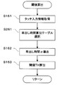
以下、第2の実施形態におけるECU13の処理について説明する。第2の実施形態におけるECU13の処理は図3に示すフローチャートと同様であるが、ステップS16のサブルーチンの処理が異なる。以下、第2の実施形態におけるステップS16のサブルーチンの処理について図8を用いて説明する。図8は図3に示すステップS16のサブルーチン処理の一例を示すフローチャートである。なお、図8に示す各ステップの処理のうち、図5と同じ処理を実行するステップについては同じステップ番号を付し、詳細な説明を省略する。
Hereinafter, the process of the
図8に示すフローチャートにおいて、ECU13は、ステップS161の処理を完了するとステップS261へ処理を進める。
In the flowchart shown in FIG. 8, when the
ステップS261において、ECU13は、早出し時間算出テーブルを選択する。具体的には、まず、ECU13は舵角センサから舵角Rの値を取得する。次に、舵角Rに対応した早出し時間テーブルを記憶装置から読み出す。なお、舵角Rの値に対応した各早出し時間テーブルでは、舵角Rおよびタッチ入力情報の組み合わせに応じて早出し時間αの値が予め設定される。舵角Rの値に対応した各早出し時間テーブルで示されるタッチ入力情報の組み合わせは各々共通であるが、同じタッチ入力情報の組み合わせであっても、当該組み合わせに対応する早出し時間αの値は各早出し時間テーブル毎で舵角Rの値に応じて異なる値が設定される。以下舵角Rの値が0の場合を例として説明する。
In step S <b> 261, the
図9は舵角R=0に対応した早出し時間算出テーブルの一例を示した図である。なお、第2の実施形態ではタッチセンサの数の増加に伴い、タッチ入力情報の組み合わせの数が増加している。そのため、図9に示すように、第2の実施形態における早出し時間算出テーブルは、行および列の数が第1の実施形態における早出し時間算出テーブル(図6参照)より増加する。 FIG. 9 is a diagram showing an example of an early departure time calculation table corresponding to the steering angle R = 0. In the second embodiment, the number of combinations of touch input information increases as the number of touch sensors increases. Therefore, as shown in FIG. 9, the number of rows and columns in the early search time calculation table in the second embodiment is larger than that in the quick search time calculation table (see FIG. 6) in the first embodiment.
一般的に、舵角R=0の状態、すなわち車両が直進している状態で、運転者が最も操舵操作し易いステアリングホイールの把持位置は、時計の短針で9時から10時の範囲内、および2時から3時の範囲内である。したがって、車両が直進中で、且つ時計の短針で9時から10時の範囲に配置されたタッチセンサ221(図7参照)、および時計の短針で2時から3時の範囲に配置されたタッチセンサ226(図7参照)がオン状態である場合は、自動ブレーキのタイミングを可能な限り遅くすることが望ましい。そこで、図9に示す舵角R=0に対応した早出し時間算出テーブルにおいて、タッチセンサ221およびタッチセンサ226がオン状態であるタッチ入力情報の組み合わせに対応する早出し時間αの値は、予め0に設定すると良い。なお、早出し時間算出テーブルにおいてタッチセンサ221およびタッチセンサ226がオン状態でない組み合わせに対応する早出し時間αの値は、0より大きな値に設定する。例えば、タッチセンサ228およびタッチセンサ231のみがオン状態である組み合わせに対応する早出し時間αの値は、0より大きなα3に設定する。
In general, when the steering angle is R = 0, that is, when the vehicle is traveling straight, the gripping position of the steering wheel that is most easily steered by the driver is within the range from 9 o'clock to 10 o'clock with the short hand of the watch. And within 2 to 3 o'clock. Therefore, the touch sensor 221 (see FIG. 7) is placed in the range from 9 o'clock to 10 o'clock with the short hand of the watch while the vehicle is traveling straight, and the touch is placed in the range from 2 o'clock to 3 o'clock with the short hand of the watch When the sensor 226 (see FIG. 7) is in the on state, it is desirable to delay the automatic brake timing as much as possible. Therefore, in the quick-start time calculation table corresponding to the steering angle R = 0 shown in FIG. 9, the value of the quick-start time α corresponding to the combination of touch input information in which the
なお、上記図9に示す早出し時間算出テーブルは一例であり、タッチセンサ221およびタッチセンサ226がオン状態である場合の早出し時間αの値が、タッチセンサ221およびタッチセンサ226がオン状態でない場合の早出し時間αの値より相対的に小さな値であれば、早出し時間算出テーブルで設定される早出し時間αの値は上記に限らない。
9 is merely an example, and the value of the quick advance time α when the
図8の説明に戻り、ECU13は、ステップS261の処理を完了すると、処理をステップS162へ進める。
Returning to the description of FIG. 8, when the
以上より、第2の実施形態に係る衝突防止支援装置によると、把持位置をより詳細に検出し、自動ブレーキタイミングをより詳細に決定することができる。また、運転者がステアリングホイールを片手で把持しているか否かに応じて自動ブレーキタイミングを変更することができる。また、舵角Rおよび把持位置に応じて自動ブレーキタイミングを変更することができる。その結果、運転者は、より安全に衝突回避のための操舵操作を行うことができる。 As described above, according to the collision prevention support apparatus according to the second embodiment, the gripping position can be detected in more detail, and the automatic brake timing can be determined in more detail. Further, the automatic brake timing can be changed depending on whether or not the driver holds the steering wheel with one hand. Further, the automatic brake timing can be changed according to the steering angle R and the grip position. As a result, the driver can perform a steering operation for collision avoidance more safely.
(第3の実施形態)
上記の第1の実施形態および第2の実施形態では、ECU13が、自動ブレーキタイミングを把持位置に応じて決定する例について示したが、ECU13は、把持位置に代えて、定められた時点の前後で把持位置が変化したか否かに応じて自動ブレーキタイミングを決定しても構わない。以下、第3の実施形態について詳細に説明する。
(Third embodiment)
In the first embodiment and the second embodiment described above, the
第3の実施形態において、ECU13は、車両に搭載される警報装置と接続される。警報装置は、一般的には警報音を発するブザーである。ECU13は、車両と障害物が接近した場合、自動ブレーキを開始する以前の時点で、警報装置を動作する指示信号を出力する。警報装置が動作した時点の前後で、把持位置が変化した場合、運転者は警報により衝突の危険を認識して、衝突を回避する操舵操作のためステアリングホイール持ち替えたと考えられる。したがって、ECU13は、警報装置が動作した時点の前後で把持位置が変化した場合、運転者の操舵操作を邪魔しないよう自動ブレーキタイミングを必要以上に早くしないように早出し時間αの値を小さい値に変更する。
In the third embodiment, the
以下、図10を参照して第3の変形例におけるECU13の処理について説明する。なお、図10はECU13によって実行される処理の一例を示すフローチャートである。図10に示す各ステップのうち、図3と同じ処理を実行するステップについては同じステップ番号を付し、詳細な説明を省略する。
Hereinafter, the processing of the
図10に示すフローチャートにおいて、ECU13は、ステップS11の処理を完了するとステップS31へ処理を進める。
In the flowchart shown in FIG. 10, when the
ステップS31において、ECU13は、タッチ入力情報を取得する。具体的には、ECU13は、各タッチセンサが各々オン状態であるかオフ状態であるかを示す信号を取得し、各タッチセンサの状態を記憶装置に記憶する。ECU13はステップS161の処理を完了すると処理をステップS12へ進める。
In step S31, the
ECU13は、ステップS12の処理を完了するとステップS32へ処理を進める。
When the
ステップS32において、ECU13は、衝突予想時間TTCの値が警報時間TAの値より小さいか否かを判定する。具体的には、ECU13は、記憶装置に記憶された衝突予想時間TTCの値、および予め記憶装置に記憶された定数である警報時間TAの値を読み出し、各々の大きさを比較する。ECU13は、衝突予想時間TTCの値が警報時間TAの値より小さいと判断した場合、処理をステップS33へ進める。一方、ECU13は、衝突予想時間TTCの値が警報時間TAの値以上であると判断した場合、処理をステップS34へ進める。
In step S32, the
ステップS33において、ECU13は、警報を開始する。具体的には、ECU13は、警報装置に対して警報動作を開始する指示信号を出力する。ECU13は、ステップS33の処理を完了すると、処理をステップS13へ進める。
In step S33, the
ステップS34において、ECU13は、警報を停止する。具体的には、ECU13は、警報装置に対して警報動作を停止する指示信号を出力する。ECU13は、ステップS34の処理を完了すると、処理をステップS11へ戻す。
In step S34, the
上記に説明したステップS32からステップS34の処理により、衝突予想時間TTCが警報時間TAに達した時点で警報装置が動作して警報が発せられる。 By the processing from step S32 to step S34 described above, the alarm device operates to issue an alarm when the estimated collision time TTC reaches the alarm time TA.
ステップS15において、操舵限界時間TSの値が制動限界時間TBの値より小さい場合、ECU13は、処理をステップS35へ進める。
In step S15, when the value of the steering limit time TS is smaller than the value of the braking limit time TB, the
ステップS35において、ECU13は、閾値THを算出する。具体的には、ECU13は、警報が発報された後のタッチ入力情報を取得する。そして、警報が発報される前後のタッチ入力情報を比較し、タッチ入力情報が変化している場合、早出し時間αの値を0として閾値THを算出する。以下、図11を参照してステップS35のサブルーチン処理の詳細について説明する。なお、図11はステップS35のサブルーチン処理の一例を示すフローチャートである。図11に示す各ステップのうち、図5と同じ処理を実行するステップについては同じステップ番号を付し、詳細な説明を省略する。
In step S35, the
ステップS161において、ECU13は、タッチ入力情報を取得する。具体的な処理は上記に説明した通りであるが、ここで、ECU13は、本ステップS161で取得したタッチ入力情報をステップS31(図10参照)で取得したタッチ入力情報とは別の領域で記憶装置に記憶する。ECU13は、ステップS161の処理を完了すると処理をステップS361へ処理を進める。
In step S161, the
ステップS361において、ECU13は、警報発報前後で把持位置が変化しているか否かを判定する。具体的には、ECU13は、直前のステップS161で取得したタッチ入力情報と、ステップS31で取得したタッチ入力情報とが異なっているか比較する。ECU13は、直前のステップS161で取得したタッチ入力情報と、ステップS31で取得したタッチ入力情報とが異なっている場合、警報発報前後で把持位置が変化していると判定し、処理をステップS362へ進める。一方、ECU13は、直前のステップS161で取得したタッチ入力情報と、ステップS31で取得したタッチ入力情報とが一致する場合、警報発報前後で把持位置が変化していないと判定し、処理をステップS162へ進める。
In step S361, the
ステップS362において、ECU13は、早出し時間αの値を0にする。なお、運転者の操舵操作を邪魔しないタイミングで自動ブレーキを開始可能であれば、本ステップS362で設定する早出し時間αの値は0に限らない。ECU13はステップS362の処理を完了すると、処理はステップS163へ進める。
In step S362, the
上記に説明したステップS31、ステップS32、ステップS35の処理により、警報発報前後の把持位置の変化を検出し、該変化に応じて閾値THの値を算出することができる。 By the processes in steps S31, S32, and S35 described above, a change in the grip position before and after the alarm is generated can be detected, and the value of the threshold TH can be calculated in accordance with the change.
以上より、第3の実施形態に係る衝突防止支援装置によると、警報装置が動作した時点の前後で把持位置が変化したか否かに応じて、自動ブレーキタイミングを変更することができる。したがって、運転者が警報により衝突の回避を意識している場合に、不要な自動ブレーキの作動を抑制することができる。 As described above, according to the collision prevention support device according to the third embodiment, the automatic brake timing can be changed according to whether or not the gripping position has changed before and after the time when the alarm device is operated. Therefore, when the driver is conscious of avoiding a collision by an alarm, unnecessary automatic brake operation can be suppressed.
なお、上記の第1〜第3の実施形態では、ステアリングホイールに、タッチ入力の有無だけを検知するタッチセンサを複数個備える例を示したが、入力面のどの位置にタッチ入力されているかを検出可能なタッチセンサを用いても良い。このようなタッチセンサで、ステアリングホイールのリム部表面全体を一つの入力面とすれば、少ない部品点数で詳細な把持位置を検出することができる。 In the first to third embodiments described above, the steering wheel is provided with a plurality of touch sensors that detect only the presence or absence of touch input. A detectable touch sensor may be used. With such a touch sensor, if the entire rim surface of the steering wheel is used as one input surface, a detailed gripping position can be detected with a small number of parts.
また、上記の第1〜第3の実施形態では、ステアリングホイールに配置されたタッチセンサへの入力に基づいて、把持位置を検出する例について説明したが、把持位置を検出する方法は上記タッチセンサを用いる方法に限らない。例えば、車内に搭載されたカメラで運転者がステアリングホイールを把持する様子を撮影し、該カメラで撮影された画像(以下、カメラ画像と呼称する)に基づいて把持位置が検出されても良い。このように、カメラ画像に基づいて把持位置を検出する場合、ECU13はカメラ画像を取得する。そして、ECU13は、取得したカメラ画像を、カメラ画像中のステアリングホイールの位置および運転者の手の位置を認識することにより把持位置を検出する。
In the first to third embodiments, the example in which the grip position is detected based on the input to the touch sensor disposed on the steering wheel has been described. However, the method for detecting the grip position is the touch sensor. It is not restricted to the method of using. For example, a situation where the driver holds the steering wheel with a camera mounted in the vehicle may be photographed, and the gripping position may be detected based on an image photographed by the camera (hereinafter referred to as a camera image). Thus, when detecting a holding position based on a camera image, ECU13 acquires a camera image. Then, the
本発明に係る衝突防止支援装置は、運転者が把持するステアリングホイールのリム部の把持状態に応じて自動的な制動動作を開始するタイミングを決定できる衝突防止支援装置などとして用いることができる。 The anti-collision assistance device according to the present invention can be used as an anti-collision assistance device that can determine the timing for starting an automatic braking operation in accordance with the gripping state of the rim portion of the steering wheel gripped by the driver.
11 ミリ波レーダー
13 ECU
14 ブレーキ制御装置
121、122、221〜232 タッチセンサ
11
14
Claims (8)
運転者が把持するステアリングホイールのリム部の把持状態を検出する把持状態検出手段と、
前記障害物と前記車両とが衝突すると予測された場合、自動ブレーキを開始する自動ブレーキタイミングを前記把持状態に応じて決定する自動ブレーキタイミング決定手段と、
前記自動ブレーキタイミングで前記自動ブレーキを実行するブレーキ手段とを備える衝突防止支援装置。 A collision prediction means for predicting a collision between an obstacle existing around the vehicle and the vehicle;
Gripping state detecting means for detecting the gripping state of the rim portion of the steering wheel gripped by the driver;
When it is predicted that the obstacle and the vehicle will collide, automatic brake timing determining means for determining automatic brake timing for starting automatic braking according to the gripping state;
A collision prevention support device comprising: brake means for executing the automatic brake at the automatic brake timing.
前記自動ブレーキタイミング決定手段は、前記把持位置に応じて前記自動ブレーキタイミングを決定する、請求項1に記載の衝突防止支援装置。 The grip state detection means includes a grip position detection means for detecting a grip position where a driver grips the rim portion of the steering wheel,
The collision prevention assisting apparatus according to claim 1, wherein the automatic brake timing determining means determines the automatic brake timing according to the gripping position.
前記画像をもとに前記把持位置を検出する、請求項2に記載の衝突防止支援装置。 The grip position detection means includes an imaging device that captures an image including a rim portion of the steering wheel and a driver's hand gripping the rim portion,
The collision prevention support apparatus according to claim 2, wherein the grip position is detected based on the image.
前記自動ブレーキタイミング決定手段は、前記舵角および前記把持位置に応じて前記自動ブレーキタイミングを決定する、請求項2に記載の衝突防止支援装置。 A steering angle detecting means for detecting a steering angle of the steering wheel;
The collision prevention support apparatus according to claim 2, wherein the automatic brake timing determination unit determines the automatic brake timing according to the steering angle and the grip position.
前記把持状態検出手段は、前記把持位置の変化を検出する把持位置変化検出手段を含み、
前記自動ブレーキタイミング決定手段は、前記警報装置が動作する前後で前記把持位置の変化が検出された場合、前記把持位置の変化が検出されない場合に比べて前記自動ブレーキタイミングを相対的に遅くする、請求項1に記載の衝突防止支援装置。 When it is predicted that the obstacle and the vehicle will collide, further comprising an alarm control means for operating an alarm device at a timing earlier than the automatic brake timing,
The gripping state detection means includes gripping position change detection means for detecting a change in the gripping position,
The automatic brake timing determining means relatively delays the automatic brake timing when a change in the gripping position is detected before and after the alarm device is operated, compared to a case in which a change in the gripping position is not detected; The collision prevention support device according to claim 1.
前記自動ブレーキタイミング決定手段は、運転者が前記リム部を片手で把持している場合、前記リム部を両手で把持している場合に比べて前記自動ブレーキタイミングを相対的に早くする、請求項1に記載の衝突防止支援装置。 The gripping state detection means includes gripping hand determination means for determining whether the driver is gripping the rim part with one hand or with both hands,
The automatic brake timing determination means makes the automatic brake timing relatively earlier when a driver is holding the rim part with one hand than when the driver is holding the rim part with both hands. The collision prevention support apparatus according to 1.
Priority Applications (1)
| Application Number | Priority Date | Filing Date | Title |
|---|---|---|---|
| JP2008052302A JP2009208559A (en) | 2008-03-03 | 2008-03-03 | Collision prevention assistant device |
Applications Claiming Priority (1)
| Application Number | Priority Date | Filing Date | Title |
|---|---|---|---|
| JP2008052302A JP2009208559A (en) | 2008-03-03 | 2008-03-03 | Collision prevention assistant device |
Publications (1)
| Publication Number | Publication Date |
|---|---|
| JP2009208559A true JP2009208559A (en) | 2009-09-17 |
Family
ID=41182142
Family Applications (1)
| Application Number | Title | Priority Date | Filing Date |
|---|---|---|---|
| JP2008052302A Pending JP2009208559A (en) | 2008-03-03 | 2008-03-03 | Collision prevention assistant device |
Country Status (1)
| Country | Link |
|---|---|
| JP (1) | JP2009208559A (en) |
Cited By (12)
| Publication number | Priority date | Publication date | Assignee | Title |
|---|---|---|---|---|
| JP2011121554A (en) * | 2009-12-14 | 2011-06-23 | Denso Corp | Wheel gripping detecting device for steering device and program |
| JP2014061761A (en) * | 2012-09-20 | 2014-04-10 | Yuhshin Co Ltd | On-vehicle equipment operating device |
| JP2014516873A (en) * | 2011-06-22 | 2014-07-17 | ティーケー ホールディングス インク. | Sensor system for a vehicle steering wheel |
| WO2014123222A1 (en) * | 2013-02-08 | 2014-08-14 | 株式会社フジクラ | Capacitance sensor and steering |
| JP2015145156A (en) * | 2014-01-31 | 2015-08-13 | 日野自動車株式会社 | Automatic brake control device |
| JP2015186957A (en) * | 2014-03-26 | 2015-10-29 | 本田技研工業株式会社 | Interacting state determination device |
| WO2017033767A1 (en) * | 2015-08-21 | 2017-03-02 | 株式会社東海理化電機製作所 | Operating device for vehicles |
| JP2018047895A (en) * | 2010-04-02 | 2018-03-29 | ティーケー ホールディングス,インコーポレーテッド | Steering wheel sensing pressure of hand |
| JP2020040581A (en) * | 2018-09-12 | 2020-03-19 | 本田技研工業株式会社 | Determination system, vehicle control system, vehicle, determination method, and program |
| US11142213B2 (en) * | 2016-04-22 | 2021-10-12 | Bayerische Motoren Werke Aktiengesellschaft | Longitudinal control system for a motor vehicle |
| JP2021175631A (en) * | 2020-05-01 | 2021-11-04 | 株式会社東海理化電機製作所 | Vehicular steering device |
| US11993252B2 (en) | 2020-12-16 | 2024-05-28 | Subaru Corporation | Vehicle control apparatus |
-
2008
- 2008-03-03 JP JP2008052302A patent/JP2009208559A/en active Pending
Cited By (14)
| Publication number | Priority date | Publication date | Assignee | Title |
|---|---|---|---|---|
| JP2011121554A (en) * | 2009-12-14 | 2011-06-23 | Denso Corp | Wheel gripping detecting device for steering device and program |
| JP2018047895A (en) * | 2010-04-02 | 2018-03-29 | ティーケー ホールディングス,インコーポレーテッド | Steering wheel sensing pressure of hand |
| JP2014516873A (en) * | 2011-06-22 | 2014-07-17 | ティーケー ホールディングス インク. | Sensor system for a vehicle steering wheel |
| JP2014061761A (en) * | 2012-09-20 | 2014-04-10 | Yuhshin Co Ltd | On-vehicle equipment operating device |
| JP5947919B2 (en) * | 2013-02-08 | 2016-07-06 | 株式会社フジクラ | Capacitance sensor and steering |
| WO2014123222A1 (en) * | 2013-02-08 | 2014-08-14 | 株式会社フジクラ | Capacitance sensor and steering |
| JP2015145156A (en) * | 2014-01-31 | 2015-08-13 | 日野自動車株式会社 | Automatic brake control device |
| JP2015186957A (en) * | 2014-03-26 | 2015-10-29 | 本田技研工業株式会社 | Interacting state determination device |
| WO2017033767A1 (en) * | 2015-08-21 | 2017-03-02 | 株式会社東海理化電機製作所 | Operating device for vehicles |
| US11142213B2 (en) * | 2016-04-22 | 2021-10-12 | Bayerische Motoren Werke Aktiengesellschaft | Longitudinal control system for a motor vehicle |
| JP2020040581A (en) * | 2018-09-12 | 2020-03-19 | 本田技研工業株式会社 | Determination system, vehicle control system, vehicle, determination method, and program |
| JP7066582B2 (en) | 2018-09-12 | 2022-05-13 | 本田技研工業株式会社 | Judgment system, vehicle control system, vehicle, judgment method, and program |
| JP2021175631A (en) * | 2020-05-01 | 2021-11-04 | 株式会社東海理化電機製作所 | Vehicular steering device |
| US11993252B2 (en) | 2020-12-16 | 2024-05-28 | Subaru Corporation | Vehicle control apparatus |
Similar Documents
| Publication | Publication Date | Title |
|---|---|---|
| JP2009208559A (en) | Collision prevention assistant device | |
| US6768962B2 (en) | Method for sensing the readiness of a driver to steer | |
| US9517719B2 (en) | Method and device for automatic direction indication | |
| JP4811025B2 (en) | Vehicle control device | |
| JP6661225B2 (en) | Control support vehicle | |
| EP3323688B1 (en) | Start control device and start control method | |
| JP2015205558A (en) | Travel support apparatus | |
| JP6300181B2 (en) | Vehicle control device | |
| WO2012098667A1 (en) | Drive assisting apparatus | |
| JP2017146817A (en) | Cruise control unit | |
| JP6631802B2 (en) | Grasping state judgment device | |
| JP2016122393A (en) | Collision avoidance support device | |
| JPWO2018011872A1 (en) | Driving assistance device | |
| JP2008282279A (en) | Object detection device | |
| CN107031397B (en) | Driver fatigue state warning system and method thereof | |
| CN104802797B (en) | Range information system and automobile for automobile | |
| JP2011126337A (en) | Drive support device | |
| JP6819173B2 (en) | Driving support method and driving support device | |
| US9187037B2 (en) | Stop lamp switch abnormality detecting device | |
| KR20160033524A (en) | Parking assist apparatus and method with parking mode selecting function | |
| WO2015156209A1 (en) | Recognition support system and recognition support method | |
| JP2008049959A (en) | Device for supporting contact avoidance of vehicle | |
| JP2017033080A (en) | Direction indicator controller | |
| JP2016217845A (en) | Abnormality detection device | |
| JP4385852B2 (en) | Vehicle handling support device |