JP2009200869A - Narrow directional capacitor microphone - Google Patents
Narrow directional capacitor microphone Download PDFInfo
- Publication number
- JP2009200869A JP2009200869A JP2008040923A JP2008040923A JP2009200869A JP 2009200869 A JP2009200869 A JP 2009200869A JP 2008040923 A JP2008040923 A JP 2008040923A JP 2008040923 A JP2008040923 A JP 2008040923A JP 2009200869 A JP2009200869 A JP 2009200869A
- Authority
- JP
- Japan
- Prior art keywords
- acoustic
- unit
- conductive
- built
- acoustic tube
- Prior art date
- Legal status (The legal status is an assumption and is not a legal conclusion. Google has not performed a legal analysis and makes no representation as to the accuracy of the status listed.)
- Granted
Links
Images


Landscapes
- Details Of Audible-Bandwidth Transducers (AREA)
- Obtaining Desirable Characteristics In Audible-Bandwidth Transducers (AREA)
- Electrostatic, Electromagnetic, Magneto- Strictive, And Variable-Resistance Transducers (AREA)
- Circuit For Audible Band Transducer (AREA)
Abstract
Description
本発明は、径方向での短寸化を実現しつつ、ハムノイズや高周波電流の入り込みを困難にして雑音の発生を抑制することができるようにした狭指向性コンデンサマイクロホンに関する技術である。 The present invention relates to a narrow-directional condenser microphone that can suppress the generation of noise by making it difficult to enter hum noise and high-frequency current while realizing shortening in the radial direction.
直径の小さな狭指向性コンデンサマイクロホンにおいては、その外筐が音響管で構成されている。また、該音響管がその周側面に備える音響抵抗孔を塞ぐ音響抵抗材は、外観を損ねることのないように、例えば下記特許文献1に開示されているように音響管の内側面側に取り付けられることになる。
この場合、前部音響端子と後部音響端子とを有するマイクロホンユニットは、音響管内の内径よりもその外径が小さいため、音響管内に収納した際に該音響管との間に空隙を確保することができるが、両者を接着剤を用いて固定する際に該空隙が塞がれてしまうことになる。 In this case, since the outer diameter of the microphone unit having the front acoustic terminal and the rear acoustic terminal is smaller than the inner diameter in the acoustic tube, a gap is secured between the acoustic unit and the acoustic tube when the acoustic unit is housed in the acoustic tube. However, when the both are fixed using an adhesive, the gap is closed.
また、マイクロホンユニットを接着剤で音響管に固定する場合には、マイクロホンユニットと音響管との間の電気的な接続状態が不安定になって十分なシールドがとれなくなくなってハムノイズや高周波電流が入り込んで雑音を発生させやすくなる。 Also, when the microphone unit is fixed to the acoustic tube with an adhesive, the electrical connection between the microphone unit and the acoustic tube becomes unstable, and sufficient shielding cannot be obtained, causing hum noise and high frequency current. It becomes easy to enter and generate noise.
このため、本願出願人は、このような場合にハムノイズや高周波電流の入り込みを困難にして雑音の発生を抑制することができるように、下記特許文献2に開示されている狭指向性コンデンサマイクロホンを提案している。
図5は、上記特許文献2に開示されている狭指向性コンデンサマイクロホンの外観例についての側面図を、図6は、音響管とマイクロホンユニットとを分離させた状態での縦端面図を、図7は、図5の縦端面図を、図8は、図7における円形囲繞部位の拡大図をそれぞれ示す。 FIG. 5 is a side view of an appearance example of a narrow directivity condenser microphone disclosed in Patent Document 2, and FIG. 6 is a vertical end view of the acoustic tube and the microphone unit separated from each other. 7 is a vertical end view of FIG. 5, and FIG. 8 is an enlarged view of the circular surrounding portion in FIG.
これらの図によれば、狭指向性コンデンサマイクロホンは、その内側面が音響抵抗材3で塞がれた音響抵抗孔2を周側面に備える音響管1と、内蔵ユニット部品8をユニットケース7内に収容して形成されるマイクロホンユニット6とで構成されている。
According to these figures, the narrow directivity condenser microphone has an
また、音響管1は、その基端部4側に位置する部位の内周面5の内径をその他の部位の内径よりも拡径できるように薄肉化することでその境界部位に段差部5aが形成されている。
Further, the
そして、マイクロホンユニット6は、図6に示すようにその前部音響端子6a側を覆うようにして介在配置される断面略コ字形を呈する導電性介装材9とともに音響管1の段差部5aに当接する位置にまで送り込まれ、図7に示すように音響管1側と一体化されることになる。
Then, as shown in FIG. 6, the
このようにして形成されるラインマイクロホンと称される狭指向性コンデンサマイクロホンは、音響管1とマイクロホンユニット6との間に導電性介装材9を介在させて相互間の電気的な導通状態を確実なものとすることができるので、ハムノイズや高周波電流の入り込みを困難にして雑音の発生を抑制することができることになる。
A narrow directivity condenser microphone called a line microphone formed in this manner has an electrical conduction state between the
ところで、ラインマイクロホンと称される狭指向性コンデンサマイクロホンには、直径の小さな狭指向性を実現するために、径方向での寸法をより短寸化したいとする要請もある。 By the way, there is a demand for a narrow directivity condenser microphone called a line microphone in order to further reduce the radial dimension in order to realize a narrow directivity with a small diameter.
しかし、上記特許文献2に開示されている狭指向性コンデンサマイクロホン(図5〜図8参照)による場合には、音響管1とマイクロホンユニット6との間に導電性介装材9を介在させることから、該導電性介装材9を介在させた分だけ径方向での寸法が大きくなり、上記要請に対応できなくなる不都合があった。
However, in the case of using the narrow directivity condenser microphone disclosed in Patent Document 2 (see FIGS. 5 to 8), the conductive
本発明は、従来技術の上記課題に鑑み、径方向での寸法をより短寸化するなかで、ハムノイズや高周波電流の入り込みをなくすことによる雑音発生の抑制や、空洞共振の発生の抑制のほか、風雑音を小さくしたり内蔵ユニットの偏心をなくすこともできる狭指向性コンデンサマイクロホンを提供することに目的がある。 In view of the above-mentioned problems of the prior art, the present invention is capable of suppressing noise generation by eliminating hum noise and high-frequency current entry while reducing the radial dimension, and suppressing occurrence of cavity resonance. An object is to provide a narrow directional condenser microphone that can reduce wind noise and eliminate the eccentricity of the built-in unit.
本発明は、上記目的を達成すべくなされたものであり、音響抵抗材で内側が覆われた音響抵抗孔をその周側面に備えた適宜長さの導電性金属材からなる音響管と、前部音響端子と後部音響端子とを備えてコンデンサマイクロホン機能を発揮させる内蔵ユニットと、該内蔵ユニットを前記前部音響端子側から覆う断面略コ字形を呈するメッシュ状弾性金属材からなる導電性介装材とで構成され、前記音響管は、前記導電性介装材で覆われた前記内蔵ユニットの外径よりもその内径を小さくして形成される段差部をその基端部側の内周面に備え、前記前記内蔵ユニットは、前記導電性介装材ともども前記音響管の基端開口から前記段差部と当接する位置にまで送り込んで前記音響管と一体化させたことを最も主要な特徴とする。 The present invention has been made in order to achieve the above object, and includes an acoustic tube made of a conductive metal material having an appropriate length and provided with an acoustic resistance hole whose inner side is covered with an acoustic resistance material, A built-in unit that includes a front acoustic terminal and a rear acoustic terminal to exert a condenser microphone function, and a conductive interposer made of a mesh-like elastic metal material having a substantially U-shaped cross section that covers the built-in unit from the front acoustic terminal side And the acoustic tube has a stepped portion formed by making its inner diameter smaller than the outer diameter of the built-in unit covered with the conductive intercalation material on the inner peripheral surface on the base end side. The built-in unit is fed back to the position where it comes into contact with the step portion from the proximal end opening of the acoustic tube together with the conductive intervening material, and is integrated with the acoustic tube. To do.
本発明における前記導電性介装材は、前記前部音響端子との対面側に向かってその周壁部がやや縮径されるテーパーが付された有底筒状を呈するようにして形成するのが好ましい。 The conductive interposing material in the present invention is formed so as to exhibit a bottomed cylindrical shape with a taper whose diameter is slightly reduced toward the side facing the front acoustic terminal. preferable.
本発明のうち、請求項1に係る発明によれば、音響管の基端部内に前部音響端子側から導電性介装材で覆った内蔵ユニットを送り込んで音響管側と一体化させることで、内蔵ユニットをユニットケース内に収容することなく配置することができるので、該ユニットケースを不要にした分だけ径方向での寸法を短寸化することができる。 According to the first aspect of the present invention, the built-in unit covered with the conductive interposing material is fed into the base end portion of the acoustic tube from the front acoustic terminal side and integrated with the acoustic tube side. Since the built-in unit can be arranged without being accommodated in the unit case, the dimension in the radial direction can be shortened as much as the unit case is unnecessary.
しかも、音響管と内蔵ユニットとの間には、導電性介装材を介在させてあるので、音響管と内蔵ユニットとの間の電気的な導通状態を確実なものとすることができ、ハムノイズや高周波電流の入り込みを困難にして雑音の発生を抑制することができる。 In addition, since a conductive intervening material is interposed between the acoustic tube and the built-in unit, the electrical continuity between the acoustic tube and the built-in unit can be ensured, and hum noise can be ensured. In addition, the generation of noise can be suppressed by making it difficult for high-frequency current to enter.
また、導電性介装材は、通気性を有するメッシュ状弾性金属材を用いて形成されているので、空洞共振の発生を抑制しつつ、音響管と内蔵ユニットとの間に実質的な通気部を確保することができることになり、前部音響端子と後部音響端子との間の圧力差を均衡させて風雑音の発生を低減させることができる。 In addition, since the conductive interstitial material is formed using a mesh-like elastic metal material having air permeability, a substantial ventilation portion is formed between the acoustic tube and the built-in unit while suppressing the occurrence of cavity resonance. Can be ensured, and the generation of wind noise can be reduced by balancing the pressure difference between the front acoustic terminal and the rear acoustic terminal.
さらに、内蔵ユニットは、導電性介装材を介して音響管側との間に空隙を介在させることなく密に弾性接触させながら、偏心させることなく配置することができる。 Furthermore, the built-in unit can be arranged without being eccentric while being in close elastic contact with the acoustic tube side through the conductive interposing material without interposing a gap.
また、請求項2に係る発明によれば、導電性介装材が前部音響端子との対面側に向かってその周壁部がやや縮径されるテーパーが付された有底筒状を呈して形成されているので、音響管の基端部内に位置する段差部に向けて圧入するようにして配置することで、内蔵ユニットと音響管とをより確実に電気的に接続させた状態のもとで位置固定することができる。 Moreover, according to the invention which concerns on Claim 2, the electroconductive intervention material exhibits the bottomed cylindrical shape to which the taper by which the surrounding wall part is diameter-reduced a little toward the facing side with a front part acoustic terminal was attached. Since it is formed, the built-in unit and the acoustic tube are more securely electrically connected by placing them so as to be pressed into the stepped portion located in the base end portion of the acoustic tube. The position can be fixed with.
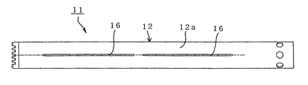
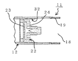
図1は、本発明の外観例についての側面図を、図2は、音響管と内蔵ユニットと導電性介装材とを相互に分離した状態での説明図を、図3は、図1の縦断面図を、図4は、図3における円形囲繞部位の拡大図をそれぞれ示す。 FIG. 1 is a side view of an external appearance example of the present invention, FIG. 2 is an explanatory diagram in a state where an acoustic tube, a built-in unit, and a conductive intercalation material are separated from each other, and FIG. FIG. 4 is a longitudinal sectional view, and FIG. 4 is an enlarged view of the circular encircling region in FIG.
これらの図によれば、狭指向性コンデンサマイクロホン11は、図1および図3からも明らかなように音響抵抗材17で内側が覆われた音響抵抗孔16をその周側面12aに備えた適宜長さの導電性金属材からなる音響管12と、前部音響端子23と後部音響端子24とを備えてコンデンサマイクロホン機能を発揮させための所要部品で構成された内蔵ユニット22と、該内蔵ユニット22を前部音響端子23側から覆う断面略コ字形を呈するメッシュ状弾性金属材からなる導電性介装材32とで構成されている。
According to these figures, the narrow
このうち、略円筒形状を呈する音響管11は、収容される内蔵ユニット22側の外径との関係で定まる適宜の内径を有するアルミニウム管材等の導電性の金属管材を用いて形成されている。
Among these, the
しかも、音響管12は、導電性介装材32で覆われた内蔵ユニット22の外径よりもその内径を小さくして、すなわち内側の肉厚を他の部位よりも薄くすることで形成される段差部15をその基端部13側の内周面14に備えている。なお、図中の符号19は、図示しないグリップ側と螺合連結させるための雌ねじ部を示す。
Moreover, the
また、ユニットケース内に収容されることなく剥き出し状に形成される内蔵ユニット22は、コンデンサマイクロホン機能を発揮させために必要な所要の部品を所定の手順で組み合わせて形成されるものであり、その前端側には前部音響端子23が、後端側には後部音響端子24がそれぞれ配置されている。
The built-in
一方、導電性介装材32は、メッシュ状弾性金属材、例えばφ0.1mmで#100のステンレスメッシュを絞り加工することで、内蔵ユニット22における前部音響端子23が位置する面とその周面部位(後部音響端子24側を除く)を密に覆うことができる形状が付与されて形成されている。
On the other hand, the
これを具体的に説明すれば、導電性介装材32は、図示例のように前部音響端子23側と対面する底部33方向に向けてその周壁部34がやや縮径されるテーパーが付された有底筒状を呈するように例えば絞り加工を施すなどして形成されている。なお、導電性介装材32は、図示例のようにテーパーを付すことなく周壁部34の全体を同径に形成するものであってもよい。
Specifically, the conductive
この場合、導電性介装材32は、その底部33側の内径が内蔵ユニット22の前部音響端子23が位置する面の外径と略一致する程度の寸法を備えている。また、音響管12がその基端部13側の内周面14に備える段差部15は、導電性介装材32をその底部33を介して当接・掛止させることができる程度の内径が付与されて形成されている。
In this case, the
上記構成からなる音響管12と内蔵ユニット22と導電性介装材32とは、例えば次のようにして組み立てられる。すなわち、図2に示されているように導電性介装材32の開口35側には、内蔵ユニット12における前部音響端子23側を対面させ、該前部音響端子23を導電性介装材32の底部33との当接位置にまで送り込む。
The
このようにして内蔵ユニット22と導電性介装材32とを組み合わせた後は、導電性介装材32の底部33を音響管12の基端開口18に向けた状態のもとで基端部14内に内蔵ユニット22ともども送り込む。
After combining the built-in
この際、内蔵ユニット22を覆う導電性介装材32は、その底部33を介して音響管12の基端部13側の内周面14に設けられている段差部15に前方音響端子23側とともに安定的に当接支持されることになる。
At this time, the conductive interposing
しかも、音響管12の基端部13側の内周面14と内蔵ユニット22の前部音響端子23を含む外周側との間には、メッシュ状弾性金属材からなる導電性介装材32が通気性を伴って密に介在配置されることになる。また、テーパーが付された導電性介装材32を用いる場合には、より密着させた状態のもとで音響管12の基端部13側の内周面14と内蔵ユニット22との間に介在させることができる。
Moreover, between the inner
したがって、内蔵ユニット22は、偏心させることなく音響管12の基端部13内に配置することができるほか、音響管12との電気的な導通状態を確実なものとすることができるので、ハムノイズや高周波電流の入り込みを困難にして雑音の発生を抑制することができる。
Therefore, the built-in
さらに、導電性介装材32は、通気性を有するメッシュ状弾性金属材を用いて形成されているので、空洞共振の発生を抑制しつつ、音響管12と内蔵ユニット22との間に実質的な通気部を確保することができることになり、前部音響端子23と後部音響端子24との間の圧力差を均衡させて風雑音の発生を低減させることができる。
Furthermore, since the
しかも、本発明によれば、音響管12の基端部13内に前部音響端子23側から導電性介装材32で覆った内蔵ユニット22を前部音響端子23側を頭にして送り込んで音響管12側と一体化させることで、内蔵ユニット22をユニットケース内に収容することなく配置することができるので、該ユニットケースを不要にした分だけ径方向での寸法を短寸化することができる。つまり、音響管12は、より細径化させて使用することができることになる。
Moreover, according to the present invention, the built-in
11 狭指向性コンデンサマイクロホン
12 音響管
12a 周側面
13 基端部
14 内周面
15 段差部
16 音響抵抗孔
17 音響抵抗材
18 基端開口
19 雌ねじ部
22 内蔵ユニット
23 前部音響端子
24 後部音響端子
32 導電性介装材
33 底部
34 周壁部
35 開口
DESCRIPTION OF
Claims (2)
前記音響管は、前記導電性介装材で覆われた前記内蔵ユニットの外径よりもその内径を小さくして形成される段差部をその基端部側の内周面に備え、
前記前記内蔵ユニットは、前記導電性介装材ともども前記音響管の基端開口から前記段差部と当接する位置にまで送り込んで前記音響管と一体化させたことを特徴とする狭指向性コンデンサマイクロホン。 Capacitor microphone function with an acoustic tube made of conductive metal material of appropriate length with an acoustic resistance hole covered on the inner side with an acoustic resistance material, and a front acoustic terminal and a rear acoustic terminal A built-in unit, and a conductive interstitial material made of a mesh-like elastic metal material having a substantially U-shaped cross section covering the built-in unit from the front acoustic terminal side,
The acoustic tube is provided with a stepped portion formed on the inner peripheral surface thereof on the base end side, which is formed by making the inner diameter smaller than the outer diameter of the built-in unit covered with the conductive intervention material,
Narrow directional condenser microphone, wherein the built-in unit is fed together with the conductive intercalation material from the proximal end opening of the acoustic tube to a position where it comes into contact with the stepped portion and integrated with the acoustic tube. .
Priority Applications (1)
| Application Number | Priority Date | Filing Date | Title |
|---|---|---|---|
| JP2008040923A JP5129605B2 (en) | 2008-02-22 | 2008-02-22 | Narrow directivity condenser microphone |
Applications Claiming Priority (1)
| Application Number | Priority Date | Filing Date | Title |
|---|---|---|---|
| JP2008040923A JP5129605B2 (en) | 2008-02-22 | 2008-02-22 | Narrow directivity condenser microphone |
Publications (2)
| Publication Number | Publication Date |
|---|---|
| JP2009200869A true JP2009200869A (en) | 2009-09-03 |
| JP5129605B2 JP5129605B2 (en) | 2013-01-30 |
Family
ID=41143884
Family Applications (1)
| Application Number | Title | Priority Date | Filing Date |
|---|---|---|---|
| JP2008040923A Expired - Fee Related JP5129605B2 (en) | 2008-02-22 | 2008-02-22 | Narrow directivity condenser microphone |
Country Status (1)
| Country | Link |
|---|---|
| JP (1) | JP5129605B2 (en) |
Cited By (4)
| Publication number | Priority date | Publication date | Assignee | Title |
|---|---|---|---|---|
| US20110142265A1 (en) * | 2009-12-16 | 2011-06-16 | Hiroshi Akino | Capacitor microphone unit and capacitor microphone |
| JP2012023544A (en) * | 2010-07-14 | 2012-02-02 | Audio Technica Corp | Narrow directional capacitor microphone |
| US8837756B2 (en) | 2011-12-08 | 2014-09-16 | Kabushiki Kaisha Audio-Technica | Dynamic microphone unit and dynamic microphone |
| US10014582B2 (en) | 2013-03-15 | 2018-07-03 | Lg Electronics Inc. | Antenna module and mobile terminal including same |
Citations (5)
| Publication number | Priority date | Publication date | Assignee | Title |
|---|---|---|---|---|
| JPH056999U (en) * | 1991-06-28 | 1993-01-29 | 株式会社オーデイオテクニカ | Condenser microphone unit |
| JPH0534794U (en) * | 1991-10-08 | 1993-05-07 | 株式会社オーデイオテクニカ | Line microphone acoustic tube |
| JPH0725692U (en) * | 1993-09-30 | 1995-05-12 | 株式会社オーディオテクニカ | Anti-vibration structure of line microphone |
| JP2006081075A (en) * | 2004-09-13 | 2006-03-23 | Audio Technica Corp | Narrow directional capacitor microphone |
| JP2006217003A (en) * | 2005-02-01 | 2006-08-17 | Audio Technica Corp | Condenser microphone |
-
2008
- 2008-02-22 JP JP2008040923A patent/JP5129605B2/en not_active Expired - Fee Related
Patent Citations (5)
| Publication number | Priority date | Publication date | Assignee | Title |
|---|---|---|---|---|
| JPH056999U (en) * | 1991-06-28 | 1993-01-29 | 株式会社オーデイオテクニカ | Condenser microphone unit |
| JPH0534794U (en) * | 1991-10-08 | 1993-05-07 | 株式会社オーデイオテクニカ | Line microphone acoustic tube |
| JPH0725692U (en) * | 1993-09-30 | 1995-05-12 | 株式会社オーディオテクニカ | Anti-vibration structure of line microphone |
| JP2006081075A (en) * | 2004-09-13 | 2006-03-23 | Audio Technica Corp | Narrow directional capacitor microphone |
| JP2006217003A (en) * | 2005-02-01 | 2006-08-17 | Audio Technica Corp | Condenser microphone |
Cited By (5)
| Publication number | Priority date | Publication date | Assignee | Title |
|---|---|---|---|---|
| US20110142265A1 (en) * | 2009-12-16 | 2011-06-16 | Hiroshi Akino | Capacitor microphone unit and capacitor microphone |
| US8526664B2 (en) * | 2009-12-16 | 2013-09-03 | Kabushiki Kaisha Audio-Technica | Capacitor microphone unit and capacitor microphone |
| JP2012023544A (en) * | 2010-07-14 | 2012-02-02 | Audio Technica Corp | Narrow directional capacitor microphone |
| US8837756B2 (en) | 2011-12-08 | 2014-09-16 | Kabushiki Kaisha Audio-Technica | Dynamic microphone unit and dynamic microphone |
| US10014582B2 (en) | 2013-03-15 | 2018-07-03 | Lg Electronics Inc. | Antenna module and mobile terminal including same |
Also Published As
| Publication number | Publication date |
|---|---|
| JP5129605B2 (en) | 2013-01-30 |
Similar Documents
| Publication | Publication Date | Title |
|---|---|---|
| US9654865B2 (en) | Earphone | |
| JP2011228833A (en) | Earphone | |
| US20110135136A1 (en) | Customized earphone | |
| WO2015165310A1 (en) | Noise reduction bone conduction vibrator | |
| US10075781B2 (en) | Microphone | |
| JP6053161B2 (en) | Condenser microphone | |
| JP5534851B2 (en) | Narrow directional microphone | |
| JP5129605B2 (en) | Narrow directivity condenser microphone | |
| US8744110B2 (en) | Unidirectional dynamic microphone | |
| JP4095927B2 (en) | Condenser microphone unit | |
| JP5586518B2 (en) | Gooseneck condenser microphone | |
| JP4393297B2 (en) | Condenser microphone | |
| CN102196328B (en) | Microphone-unit supporting structure and electronic device | |
| WO2015165307A1 (en) | Bone conduction vibrator with adjustable high and low frequency sound effects | |
| JP4383956B2 (en) | Condenser microphone | |
| JP4248467B2 (en) | Narrow directivity condenser microphone | |
| JP2008053807A (en) | Non-directional dynamic microphone | |
| JP5058587B2 (en) | Electret condenser microphone unit and electret condenser microphone | |
| WO2015165309A1 (en) | Piezoelectric quartz bone conduction vibrator | |
| US10506352B2 (en) | Microphone unit with a housing and hearing aid having the microphone unit | |
| JP4972473B2 (en) | Condenser microphone | |
| JP6239379B2 (en) | Volume reduction filling member for microphone and unidirectional condenser microphone incorporating the same | |
| WO2017071109A1 (en) | Cylindrical contact-type microphone | |
| CN210579148U (en) | Tunable TWS earphone | |
| JP5737846B2 (en) | Dynamic microphone |
Legal Events
| Date | Code | Title | Description |
|---|---|---|---|
| A621 | Written request for application examination |
Free format text: JAPANESE INTERMEDIATE CODE: A621 Effective date: 20110126 |
|
| A977 | Report on retrieval |
Free format text: JAPANESE INTERMEDIATE CODE: A971007 Effective date: 20120604 |
|
| A131 | Notification of reasons for refusal |
Free format text: JAPANESE INTERMEDIATE CODE: A131 Effective date: 20120620 |
|
| A521 | Written amendment |
Free format text: JAPANESE INTERMEDIATE CODE: A523 Effective date: 20120803 |
|
| TRDD | Decision of grant or rejection written | ||
| A01 | Written decision to grant a patent or to grant a registration (utility model) |
Free format text: JAPANESE INTERMEDIATE CODE: A01 Effective date: 20121003 |
|
| A01 | Written decision to grant a patent or to grant a registration (utility model) |
Free format text: JAPANESE INTERMEDIATE CODE: A01 |
|
| A61 | First payment of annual fees (during grant procedure) |
Free format text: JAPANESE INTERMEDIATE CODE: A61 Effective date: 20121102 |
|
| R150 | Certificate of patent or registration of utility model |
Free format text: JAPANESE INTERMEDIATE CODE: R150 |
|
| FPAY | Renewal fee payment (event date is renewal date of database) |
Free format text: PAYMENT UNTIL: 20151109 Year of fee payment: 3 |
|
| LAPS | Cancellation because of no payment of annual fees |