JP2009159478A - Moving image processing circuit - Google Patents
Moving image processing circuit Download PDFInfo
- Publication number
- JP2009159478A JP2009159478A JP2007337494A JP2007337494A JP2009159478A JP 2009159478 A JP2009159478 A JP 2009159478A JP 2007337494 A JP2007337494 A JP 2007337494A JP 2007337494 A JP2007337494 A JP 2007337494A JP 2009159478 A JP2009159478 A JP 2009159478A
- Authority
- JP
- Japan
- Prior art keywords
- processing unit
- moving image
- color space
- unit
- processing circuit
- Prior art date
- Legal status (The legal status is an assumption and is not a legal conclusion. Google has not performed a legal analysis and makes no representation as to the accuracy of the status listed.)
- Pending
Links
- 238000012545 processing Methods 0.000 title claims abstract description 265
- 238000006243 chemical reaction Methods 0.000 claims abstract description 52
- 238000000034 method Methods 0.000 claims description 52
- 230000006835 compression Effects 0.000 claims description 12
- 238000007906 compression Methods 0.000 claims description 12
- 239000000872 buffer Substances 0.000 description 16
- 230000015654 memory Effects 0.000 description 9
- 238000010586 diagram Methods 0.000 description 7
- 230000000694 effects Effects 0.000 description 3
- 239000003086 colorant Substances 0.000 description 2
- 230000006870 function Effects 0.000 description 2
- 239000004973 liquid crystal related substance Substances 0.000 description 2
- 238000007726 management method Methods 0.000 description 2
- 230000005540 biological transmission Effects 0.000 description 1
- 230000001413 cellular effect Effects 0.000 description 1
- 238000012937 correction Methods 0.000 description 1
- 238000013461 design Methods 0.000 description 1
- 238000012986 modification Methods 0.000 description 1
- 230000004048 modification Effects 0.000 description 1
- 230000005236 sound signal Effects 0.000 description 1
- 238000004148 unit process Methods 0.000 description 1
Images


Classifications
-
- H—ELECTRICITY
- H04—ELECTRIC COMMUNICATION TECHNIQUE
- H04N—PICTORIAL COMMUNICATION, e.g. TELEVISION
- H04N9/00—Details of colour television systems
- H04N9/64—Circuits for processing colour signals
- H04N9/67—Circuits for processing colour signals for matrixing
-
- G—PHYSICS
- G09—EDUCATION; CRYPTOGRAPHY; DISPLAY; ADVERTISING; SEALS
- G09G—ARRANGEMENTS OR CIRCUITS FOR CONTROL OF INDICATING DEVICES USING STATIC MEANS TO PRESENT VARIABLE INFORMATION
- G09G5/00—Control arrangements or circuits for visual indicators common to cathode-ray tube indicators and other visual indicators
- G09G5/36—Control arrangements or circuits for visual indicators common to cathode-ray tube indicators and other visual indicators characterised by the display of a graphic pattern, e.g. using an all-points-addressable [APA] memory
- G09G5/363—Graphics controllers
-
- G—PHYSICS
- G09—EDUCATION; CRYPTOGRAPHY; DISPLAY; ADVERTISING; SEALS
- G09G—ARRANGEMENTS OR CIRCUITS FOR CONTROL OF INDICATING DEVICES USING STATIC MEANS TO PRESENT VARIABLE INFORMATION
- G09G2300/00—Aspects of the constitution of display devices
- G09G2300/04—Structural and physical details of display devices
- G09G2300/0421—Structural details of the set of electrodes
- G09G2300/0426—Layout of electrodes and connections
-
- G—PHYSICS
- G09—EDUCATION; CRYPTOGRAPHY; DISPLAY; ADVERTISING; SEALS
- G09G—ARRANGEMENTS OR CIRCUITS FOR CONTROL OF INDICATING DEVICES USING STATIC MEANS TO PRESENT VARIABLE INFORMATION
- G09G2340/00—Aspects of display data processing
- G09G2340/02—Handling of images in compressed format, e.g. JPEG, MPEG
-
- G—PHYSICS
- G09—EDUCATION; CRYPTOGRAPHY; DISPLAY; ADVERTISING; SEALS
- G09G—ARRANGEMENTS OR CIRCUITS FOR CONTROL OF INDICATING DEVICES USING STATIC MEANS TO PRESENT VARIABLE INFORMATION
- G09G2340/00—Aspects of display data processing
- G09G2340/06—Colour space transformation
-
- G—PHYSICS
- G09—EDUCATION; CRYPTOGRAPHY; DISPLAY; ADVERTISING; SEALS
- G09G—ARRANGEMENTS OR CIRCUITS FOR CONTROL OF INDICATING DEVICES USING STATIC MEANS TO PRESENT VARIABLE INFORMATION
- G09G2360/00—Aspects of the architecture of display systems
- G09G2360/18—Use of a frame buffer in a display terminal, inclusive of the display panel
Abstract
Description
本発明は、動画像処理回路に関し、特に所定の圧縮方式でエンコードされた動画像データをデコードするデコード処理部と、デコードされた動画像データの色空間を、異なる色空間に変換する色空間変換処理部と、色空間変換された動画像データをグラフィック処理するグラフィック処理部とを有する動画像処理回路に関する。 The present invention relates to a moving image processing circuit, and in particular, a decoding processing unit that decodes moving image data encoded by a predetermined compression method, and a color space conversion that converts a color space of the decoded moving image data into a different color space. The present invention relates to a moving image processing circuit including a processing unit and a graphic processing unit that performs graphic processing on moving image data that has undergone color space conversion.
近年、ビデオカメラ等で撮影されたデジタルの動画像や、受信した放送のデジタルの動画像を、そのまま液晶表示装置(以下、[LCD]という。)等の表示装置に表示するのではなく、所定のグラフィック処理を行った後に、表示することが行われている。 In recent years, digital moving images taken by a video camera or the like and received broadcast digital moving images are not directly displayed on a display device such as a liquid crystal display device (hereinafter referred to as “LCD”), but are displayed in a predetermined manner. After the graphic processing is performed, display is performed.
ここで、デジタルの動画像は、その容量を小さくするため、および、誤り訂正を行うために所定の圧縮方式で圧縮(エンコード)され、記録媒体に記録されたり、または、インターネット回線や放送を通じて配信されている。このため、デジタルの動画像を再生するには、所定の圧縮方式でエンコードされた動画像データをデコード処理し、フレーム単位の画像の集合である動画像データにするデコード処理部が用いられている。 Here, digital moving images are compressed (encoded) by a predetermined compression method in order to reduce the capacity and perform error correction, and are recorded on a recording medium or distributed through an Internet line or broadcast. Has been. For this reason, in order to reproduce a digital moving image, a decoding processing unit is used that decodes moving image data encoded by a predetermined compression method, and converts it into moving image data that is a set of frames. .
ここで、カラーの画像を表示するための色空間、すなわちカラースペース、には種々の方式があり、それぞれ一長一短があるため、目的に応じて最適の方式が使用されている。例えば、放送分野においては、色空間としてYUVが用いられているが、グラフィック処理では色空間としてRGBが用いられている。 Here, there are various types of color space for displaying a color image, that is, a color space, and each has advantages and disadvantages, and an optimal method is used according to the purpose. For example, in the broadcasting field, YUV is used as a color space, but RGB is used as a color space in graphic processing.
このため、デコードされた動画像を、所定のグラフィック処理を行うためには、グラフィック処理の前に、色空間YUVの動画像データ(以下、「YUVデータ」という。)を、色空間RGBの動画像データ以下、「RGBデータ」という。)に変換する色空間変換処理部と、変換されたRGB信号をグラフィック処理するグラフィック処理部とを有する動画像処理回路とが必要となる。ここで、フレーム速度が30fpsであるビデオ信号を、デコード処理と、色空間変換処理と、グラフィック処理とを行うには、1つの静止画像について1/30秒間で前記3つの処理を完了する必要がある。 Therefore, in order to perform predetermined graphic processing on the decoded moving image, moving image data in the color space YUV (hereinafter referred to as “YUV data”) is converted into a moving image in the color space RGB before the graphic processing. Hereinafter, the image data is referred to as “RGB data”. ) And a moving image processing circuit having a graphic processing unit for graphic processing of the converted RGB signal is required. Here, in order to perform a decoding process, a color space conversion process, and a graphic process on a video signal with a frame rate of 30 fps, it is necessary to complete the above three processes in 1/30 second for one still image. is there.
しかし、動画像処理回路の速度は所定の速度であるため、映像の情報量が多くグラフィック処理に時間を要する場合等には、動画像処理回路が、1/30秒間で、前記3つの処理を完了することができないことがある。処理を完了することができない場合には、いわゆる、「フレーム落ち」が発生する。しかし、公知の動画像処理回路においては、デコード処理、色空間変換処理およびグラフィック処理は、いずれも、先入れ先出し(FIFO:First In、 First Out)方式であるため、どのフレームが欠落するかは解らず、結果として不安定な動画像を表示装置に出力してしまうことがあった。特に、携帯電話等の携帯可能な動画像表示機器においては、搭載できるメモリ容量に制限があることから、不安定な動画像が発生しやすい傾向にあった。 However, since the speed of the moving image processing circuit is a predetermined speed, when the amount of video information is large and time is required for graphic processing, the moving image processing circuit performs the above three processes in 1/30 seconds. Sometimes it cannot be completed. When the process cannot be completed, so-called “frame dropping” occurs. However, in the known moving image processing circuit, the decoding process, the color space conversion process, and the graphic process are all first-in first-out (FIFO) systems, so it is not clear which frames are missing. As a result, an unstable moving image may be output to the display device. In particular, portable video display devices such as mobile phones tend to generate unstable video because of the limited memory capacity that can be installed.
なお、特開2003−150141号公報には、所定の圧縮方式でエンコードされた動画像データを入力バッファに、デコードされたYUV信号データを中間バッファに、そして色空間変換されたRGBデータを出力バッファに、それぞれ記憶し、デコード処理、色空間変換処理および出力処理を、並列処理する方法が開示されている。 Japanese Patent Laid-Open No. 2003-150141 discloses moving image data encoded by a predetermined compression method as an input buffer, decoded YUV signal data as an intermediate buffer, and RGB data subjected to color space conversion as an output buffer. In addition, a method is disclosed in which each of the data is stored and the decoding process, the color space conversion process, and the output process are processed in parallel.
しかし、特開2003−150141号公報の方法は、デコード処理と色空間変換処理に関するものであり、より負荷の大きなグラフィック処理については開示されていない。
本発明は、安定した動画像処理を行うことのできる動画像処理回路を実現することを目的とする。 An object of the present invention is to realize a moving image processing circuit capable of performing stable moving image processing.
本願発明の一態様によれば、所定の圧縮方式でエンコードされた動画像データをデコードするデコード処理部と、デコード処理部でデコードされた動画像データの色空間を、異なる色空間に変換する色空間変換処理部と、色空間変換処理部で色空間変換された動画像データをグラフィック処理するグラフィック処理部と、デコード処理部と色空間変換処理部とグラフィック処理部とを制御する制御部とを有することを特徴とする動画像処理回路が提供される。 According to one aspect of the present invention, a decoding processing unit that decodes moving image data encoded by a predetermined compression method, and a color that converts a color space of moving image data decoded by the decoding processing unit to a different color space A space conversion processing unit; a graphic processing unit that performs graphic processing on moving image data that has been color space converted by the color space conversion processing unit; and a control unit that controls the decoding processing unit, the color space conversion processing unit, and the graphic processing unit. A moving image processing circuit is provided.
本発明によれば、安定した動画像処理を行うことのできる動画像処理回路を実現することができる。 According to the present invention, a moving image processing circuit capable of performing stable moving image processing can be realized.
以下、図面を参照して本発明の実施の形態を説明する。
<動画像処理回路の構成>
最初に、図1および図2を用いて、本発明の実施の形態にかかる動画像処理回路1を有する携帯電話100、および携帯電話100の映像処理部200の構成について説明する。図1は、本実施の形態にかかる動画像処理回路1を有する携帯電話100の外観図であり、図2は、動画像処理回路1を有する映像処理部200の構成を示す構成図である。
Embodiments of the present invention will be described below with reference to the drawings.
<Configuration of moving image processing circuit>
First, the configuration of the
図1に示すように、携帯電話100は、表示部であるLCD18と、ユーザーが様々な指示を行う指示入力部17と、スピーカーである音声出力部205と、マイクである音声入力部208と、図示しないチューナ用のアンテナ202等を有する。
As shown in FIG. 1, the
携帯電話100は、通常の携帯電話としての電話機能に加えて、映像情報端末としての機能を有しており、携帯電話100は、例えばデジタルテレビ放送を受信し、ユーザーの所望のグラフィック処理を施した後に、表示部であるLCD18に表示する。
The
次に、図2を用いて、動画像処理回路1を有する映像処理部200の構成を説明する。
映像制御部201は、映像処理部200の各部を統括して制御し、チューナ選択、オーディオやビデオ等のコンテンツのファイルシステム管理、エンコードおよびデコード時の制御、再生モード設定、またはユーザーインターフェース制御等の処理動作を行う。
Next, the configuration of the
The
指示入力部17は、ユーザーの各スイッチ操作に応じた操作信号を映像制御部201に出力する。
チューナ203は、アンテナ202で受信したワンセグ放送のデジタル信号を受信する。
記憶部207は、映像制御部201を動作させるためのファームウエア、再生および制御に必要なアプリケーションプログラム、プログラムの設定データ、ビデオ等のコンテンツの管理に必要な管理データ、そしてビデオ等のコンテンツデータを記憶する。
The
The
The
LCD制御部14は、バックライトとLCDコントローラとを有し、ユーザー操作に基づく表示画面に応じたデータを映像制御部201からバス204を介して入力することによりLCD18を制御する。
The
音声出力部205は、オーディオ信号を内蔵されたアンプで増幅して出力する。
メディアプレイヤ204は、NAND型フラッシュメモリ等の外部記憶メディアと情報を入出力する。
インターフェース(I/F)部206は、USB端子や拡張コネクタ等を有し、外部機器が接続されたとき、データの入出力を制御する。
The
The
An interface (I / F)
そして、動画像処理回路1は、後述のようにチューナ203等からのビデオデータの処理を行う。
Then, the moving
次に、図3を用いて、本実施の形態にかかる動画像処理回路1の構成について説明する。図3は、本実施の形態にかかる動画像処理回路1の構成を示した構成図である。
図3に示すように、動画像処理回路1は、所定の圧縮方式でエンコードされたデジタルビデオデータ、すなわち動画像データをデコードし、YUVデータを出力するデコード処理部11と、YUVデータを、異なる色空間であるRGBに変換し、RGBデータを出力する色空間変換処理部であるRGB変換処理部12と、RGBデータをグラフィック処理し、LCD駆動部14を介して表示部であるLCD18に出力するグラフィック処理部13と、デコード処理部11とRGB変換処理部12とグラフィック処理部13とを制御する制御部15と、バッファメモリ19、20とを、有する。
Next, the configuration of the moving
As shown in FIG. 3, the moving
デコード処理部11は、デジタル放送等を経由して入力されたデジタルビデオ信号に対して、例えば、周波数デインタリーブ処理及び時間デインタリーブ処理等の後、ビタビ復号処理及びリードソロモン復号処理を行い、フレーム単位のYUVデータを出力する。
The
ここで、画像信号の色空間について説明する。光の三原色である赤(Red)、緑(Green)、青(Blue)の輝度情報を用いるRGBは、色空間の基本であり、コンピューターグラフィクス分野で広く用いられている。これに対して、多数の視聴者に効率よく映像を伝送する必要がある放送等の分野では、映像の画質もさることながら、映像の記録およびハンドリングに要するデータ量の低減化が求められるため、YUVが広く用いられている。YUVは、輝度情報(Y)と2つの色差情報(青−輝度(U)、赤−輝度(V))を使って色を表現する色空間である。そして、YUVは、人間の視覚が色の変化よりも明るさの変化に対して敏感であるという特性を利用して、色度を抑え、輝度により広い帯域やビット数を割くことにより、少ない損失で効率の良い伝送や圧縮を行うことができる。 Here, the color space of the image signal will be described. RGB using luminance information of the three primary colors red (Red), green (Green), and blue (Blue) is the basic color space, and is widely used in the field of computer graphics. On the other hand, in the field of broadcasting and the like where it is necessary to efficiently transmit video to a large number of viewers, it is required to reduce the amount of data required for video recording and handling, in addition to the image quality of the video. YUV is widely used. YUV is a color space that expresses colors using luminance information (Y) and two color difference information (blue-luminance (U), red-luminance (V)). YUV takes advantage of the characteristic that human vision is more sensitive to changes in brightness than changes in color, thereby reducing chromaticity and reducing the bandwidth and number of bits for luminance, thereby reducing loss. Efficient transmission and compression.
なお、本明細書において、[YUV]という時には、狭義のYUVに限られるものではなく、輝度情報と2つの色差情報からなる種々の色空間、すなわち色差コンポーネントである色空間を意味し、例えば、YUV、YIQ、YCC(YCbCr)またはYPbPr等を意味する。YIQは、NTSCテレビ放送で、YUVまたはYCCは、PALテレビやJFIF形式のJPEG画像で用いられている。なお、現在のデジタルビデオの分野では、慣習的に、YUVと呼称していても、実際にはYCbCrのことを指している。 In the present specification, [YUV] is not limited to YUV in a narrow sense, but means various color spaces composed of luminance information and two color difference information, that is, a color space that is a color difference component. YUV, YIQ, YCC (YCbCr) or YPbPr or the like is meant. YIQ is used for NTSC television broadcasting, and YUV or YCC is used for PAL television and JFIF format JPEG images. In the current digital video field, even though it is customarily called YUV, it actually refers to YCbCr.
本実施の形態にかかるRGB変換処理部12に、入力されるデジタルビデオの画像信号の色空間は、YUVである。このため、RGB変換処理部12は、YUVデータをRGBデータに変換することで、グラフィック処理部13のグラフィック処理が可能となる。
The color space of the digital video image signal input to the RGB
グラフィック処理部13は、上位アプリケーション等からの指示により、入力された動画像を加工処理する。上位アプリケーションからの指示は、例えば、ユーザーが指示入力部17を介して入力する。グラフィック処理部13が行う動画像の加工処理としては、例えば、3D化処理、すなわち3次元化処理である。
The
グラフィック処理部13により加工処理されたRGBデータは、LCDコントローラを有するLCD制御部14を介して、表示部であるLCD18(液晶表示装置)に出力される。
The RGB data processed by the
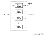
そして、本実施の形態にかかる動画像処理回路1においては、デコード処理部11とRGB変換処理部12とグラフィック処理部13とを制御する制御部15を有する。制御部15は、共通情報部16の情報を基に、予め定められた優先順位に基づいて、デコード処理部11、RGB変換処理部12またはグラフィック処理部13のいずれか1つの処理の開始を制御する。言い換えれば、動画像処理回路1においては、デコード処理部11、RGB変換処理部12およびグラフィック処理部13は、従来のFIFO方式ではなく、制御部15からの処理の開始の制御信号が入力されない限り、次のフレームの処理を開始できない。すなわち、図3に示すように、動画像処理回路1が用いるバッファメモリ19、20のフレームバッファ数は、0〜Nの(N+1)個と有限である。
The moving
このため、動画像処理回路1においては、このフレームバッファ中に蓄積されているフレームの中から、次の処理を開始するフレームが、制御部15に、より予め定められた優先順位と、共通情報部16の各フレーム情報とを基に選択される。ここで、動画像処理回路1における優先順位が、動画像データ、すなわちフレームの時間情報の場合には、選択されたフレームよりも前にフレームバッファに蓄積されていたフレームは、次の処理が行われることなく、いわゆる、フレーム落ちとなる。
For this reason, in the moving
すなわち、動画像処理回路1における、予め定められた優先順位は、動画像データの時間情報、または、デコード処理部11、RGB変換処理部12、もしくはグラフィック処理部13の処理時間の情報に基づいており、例えば、指示入力部17を介して上位アプリケーションまたはユーザーが予め指示する。動画像データの時間情報とは、動画像データを構成している各フレームのPTS(Presentation Time Stamp)情報であり、時間情報を優先順位として用いた場合には、最新のフレームに対して優先して処理が行われる。
That is, the predetermined priority order in the moving
デコード処理部11、RGB変換処理部12またはグラフィック処理部13の処理時間の情報は、上位アプリケーション等が予め設定したフレームバッファ数、制限処理時間等、または、それぞれの処理部が前フレームの処理に実際に要した処理時間の情報であり、共通情報部16に記憶されている。処理時間の情報を優先順位として用いた場合には、最も時間を要する処理に最も適した処理が行われるが、多くの場合には、グラフィック処理部13の処理に最も適した処理が行われる。
The processing time information of the
なお、共通情報部16には、デコード処理部11、RGB変換処理部12およびグラフィック処理部13のそれぞれの処理部が、処理を行っているフレームの情報がリアルタイムで入力され、制御部15は、共通情報部16の情報から、いずれか1つの処理を開始する処理部を選択する。なお、図3においては、共通情報部16は制御部15の一部として図示しているが、共通情報部16は制御部15から分離し独立した部でもよい。また、図3においては、バッファメモリ19は、デコード処理部11およびRGB変換処理部12の共用のバッファメモリとして図示しているが、それぞれが独立したバッファメモリを有していてもよいし、逆にデコード処理部11、RGB変換処理部12およびグラフィック処理部13が1の共用のバッファメモリを有していてもよい。
In addition, the
<動画像処理回路の処理>
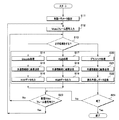
次に、図5を用いて、本実施の形態にかかる動画像処理回路1による画像信号処理の流れを説明する。図5は、本実施の形態にかかる動画像処理回路1による処理の流れを説明するためのフローチャートである。
<Processing of moving image processing circuit>
Next, the flow of image signal processing by the moving
<ステップS11>
最初に、初期パラメータが動画像処理回路1の制御部15に、指示入力部17または上位アプリケーションから入力され、初期設定が行われる。初期パラメータは、制御部15が制御に用いる優先順位のパラメータ情報等である。また、同時にグラフィック処理部13が行うグラフィック処理の内容が、指示入力部17または上位アプリケーションから制御部15に入力される。
<Step S11>
First, initial parameters are input to the
<ステップS12>
動画像処理回路1に、ビデオデータが入力される。
<Step S12>
Video data is input to the moving
<ステップS13>
動画像処理回路1の制御部15は、デコード処理部11、RGB変換処理部12またはグラフィック処理部13のいずれの処理を開始するかを、予め定められた優先順位に基づいて判断し制御する。もちろん、処理の開始時には、デコード処理のみが処理開始可能な状態であるが、時間の経過につれて、3つの処理のいずれを開始するかを制御部15が判断するため、ランダムにフレーム落ちが発生することがなく、動画像処理回路1の動作が安定である。
<Step S13>
The
<ステップS13〜S16>
制御部15が、デコード処理部11の処理の開始を選択し制御した場合には、デコード処理部11は、入力されたデジタルビデオ信号に対して、デコード処理を行い、フレーム単位のYUVデータを出力する。そして、処理したフレームの情報を共通情報部に出力する。
<Steps S13 to S16>
When the
<ステップS17〜S19>
制御部15が、RGB変換処理部12の処理の開始を選択し制御した場合には、RGB変換処理部12は、デコード処理部11が出力したYUVデータをRGBデータに変換し出力する。そして、処理したフレームの情報を共通情報部に出力する。
<Steps S17 to S19>
When the
<ステップS20〜S22>
制御部15が、グラフィック処理部13の処理の開始を選択し制御した場合には、グラフィック処理部13は、RGB変換処理部12が出力したRGBデータを、上位アプリケーションからの指示に従い所定のグラフィック処理を行い、LCD制御部14を介してLCD18に出力する。そして、処理したフレームの情報を共通情報部に出力する。
<Steps S20 to S22>
When the
なお、制御部15は、上記それぞれの処理の開始を制御するのみであり、ステップS14〜ステップS22の各処理の完了を待つことなく、制御部15は、ステップS23以降の処理を行うことができる。
Note that the
<ステップS23>
制御部15は、次のビデオデータの入力がある(Yes)場合には、ステップS12において次のビデオデータを入力する。制御部15は、次のビデオデータの入力がない(No)場合には、ステップS13において、次に処理を開始する処理を選択する。
<Step S23>
When the next video data is input (Yes), the
上記の説明のように、本実施の形態にかかる動画像処理回路1は、デコード処理部11とRGB変換処理部12とグラフィック処理部13とを制御する制御部15を有するため、これら3つの処理がFIFO方式ではなく、制御部15の制御により処理される方式である。このため、不安定な動画像処理が発生しがたく、安定した動画像処理を行うことが、できる。
As described above, since the moving
次に、図6を用いて、本実施の形態にかかる動画像処理回路1における、いわゆるフレーム落ちについて説明する。図6は、フレーム落ち現象を説明するための説明図である。図6において横軸は時間経過を示しており、F1〜FNは、フレーム単位のフレームデータを示している。なお、図6においては、説明を簡単にするために、フレームバッファ数が2と極端に少ない場合を例に説明する。
Next, a so-called frame drop in the moving
例えば、デコード処理部で、F1、F2、F3、F4の4つのフレームが処理された場合、フレームバッファ数が2しかないため、時間t1において、F3は、RGB変換処理されないで、いわゆる、フレーム落ちする。また、時間t2において、F2は、グラフィック処理時に、F2よりも最新のF4があるため、F2はグラフィック処理されないでいわゆる、フレーム落ちする。上記は、制御部15が、動画像データの時間情報に基づいて、最新のフレームを優先して処理の開始を制御している例である。
For example, when four frames F1, F2, F3, and F4 are processed by the decoding processing unit, since there are only two frame buffers, F3 is not subjected to RGB conversion processing at time t1, so-called frame dropping. To do. Further, at time t2, since F2 has the latest F4 than F2 at the time of graphic processing, F2 is not subjected to graphic processing, and a so-called frame is dropped. The above is an example in which the
このように、動画像処理回路1は、制御部15が、予め定められた優先順位に基づいて、デコード処理部11、RGB変換処理部12またはグラフィック処理部13のいずれか1つの処理の開始を制御するため、上位アプリケーションまたはユーザーが所望する安定した動画像処理をすることができる。
As described above, in the moving
さらに、動画像処理回路1は、優先順位が、動画像データの時間情報に基づく場合には最新のフレームを優先してLCD18に表示することができる。一方、動画像処理回路1は、優先順位が、デコード処理部11、RGB変換処理部12またはグラフィック処理部13の処理時間の情報に基づく場合には、それぞれの処理に最も適した処理が行われ、特にグラフィック処理部13において最も適したグラフィック処理が行われるため、ユーザーは所望のグラフィック処理された動画像を見ることができる。
Furthermore, when the priority order is based on the time information of the moving image data, the moving
本実施の形態の動画像処理回路1は、メモリ搭載量に制限のある携帯機器、特に、携帯電話に用いることで、顕著な効果を奏することができる。すなわち、所定の圧縮方式でエンコードされた動画像データをデコードするデコード処理部11と、前記デコード処理部11でデコードされた動画像データの色空間を、異なる色空間に変換する色空間変換処理部と、前記色空間変換処理部で色空間変換された動画像データをグラフィック処理するグラフィック処理部13と、前記デコード処理部11と前記色空間変換処理部と前記グラフィック処理部13とを制御する制御部15とを有する動画像処理回路1を具備した携帯電話100である。また携帯電話100の動画像処理回路1は、前記デコードされた画像データの色空間がYUVであり、前記色空間変換処理部が、色空間がYUVの信号を、色空間がRGBの信号に変換する。さらに、携帯電話100の動画像処理回路1は、前記制御部15が、予め定められた優先順位に基づいて、前記デコード処理部11、前記色空間変換処理部または前記グラフィック処理部13のいずれか1つの処理の開始を制御する。そして、携帯電話100の動画像処理回路1は、前記優先順位が、動画像データの時間情報、または、前記デコード処理部11、前記色空間変換処理部、もしくは前記グラフィック処理部13の処理時間の情報に基づいている。また、携帯電話100の動画像処理回路1は、前記所定の圧縮方式でエンコードされた動画像データが、デジタルビデオデータである。
The moving
また、動画像処理回路1は、動画を3D化処理する際に特に、顕著な効果を奏することができる。
In addition, the moving
次に、図7は、本実施の形態の動画像処理回路1の変形例の動画像処理回路2の構成を、表示した構成図である。動画像処理回路2の構成および動作は、動画像処理回路1の構成および動作と類似しているため、同じ構成要素には同じ符号を付し説明は省略する。
Next, FIG. 7 is a configuration diagram showing a configuration of a moving
図7に示す動画像処理回路2のデコード処理部11は、入力された動画像データを全て、FIFO方式でデコードする。そして、制御部15は予め定められた優先順位に基づいて、色空間変換処理部であるRGB変換処理部12またはグラフィック処理部13のいずれかの処理の開始を制御する。すなわち、動画像処理回路2は、所定の圧縮方式でエンコードされた動画像データをFIFO方式でデコードするデコード処理部と、前記デコード処理部でデコードされた動画像データの色空間を、異なる色空間に変換する色空間変換処理部と、前記色空間変換処理部で色空間変換された動画像データをグラフィック処理するグラフィック処理部と、前記色空間変換処理部と前記グラフィック処理部とを制御する制御部とを有する動画像処理回路であり、動画像処理回路2の、デコード処理部は、入力された動画像データを、FIFO方式でデコード処理する。
The
動画像処理回路2は、動画像処理回路1が有する効果に加えて、制御部15の動作が比較的簡単となるため、動画像処理回路の設計が容易である。
In the moving
本発明は、上述した実施の形態に限定されるものではなく、本発明の要旨を変えない範囲において、種々の変更、改変等が可能である。 The present invention is not limited to the above-described embodiments, and various changes and modifications can be made without departing from the scope of the present invention.
1…動画像処理回路 11…デコード処理部 12…RGB変換処理部 13…グラフィック処理部 18…LCD 15…制御部 16…共通情報部 17…指示入力部 100…携帯電話
DESCRIPTION OF
Claims (5)
前記デコード処理部でデコードされた動画像データの色空間を、異なる色空間に変換する色空間変換処理部と、
前記色空間変換処理部で色空間変換された動画像データをグラフィック処理するグラフィック処理部と、
前記デコード処理部と前記色空間変換処理部と前記グラフィック処理部とを制御する制御部とを
有することを特徴とする動画像処理回路。 A decoding processing unit for decoding moving image data encoded by a predetermined compression method;
A color space conversion processing unit for converting the color space of the moving image data decoded by the decoding processing unit into a different color space;
A graphic processing unit that performs graphic processing on the moving image data that has been color space converted by the color space conversion processing unit;
A moving image processing circuit comprising: a control unit that controls the decoding processing unit, the color space conversion processing unit, and the graphic processing unit.
前記デコードされた画像データの色空間がYUVであり、
前記色空間変換処理部が、色空間がYUVの信号を、色空間がRGBの信号に変換することを特徴とする請求項1から請求項4のいずれか1項に記載の動画像処理回路。 The moving image data encoded by the predetermined compression method is digital video data,
The color space of the decoded image data is YUV,
5. The moving image processing circuit according to claim 1, wherein the color space conversion processing unit converts a signal having a color space of YUV into a signal having a color space of RGB. 6.
Priority Applications (2)
| Application Number | Priority Date | Filing Date | Title |
|---|---|---|---|
| JP2007337494A JP2009159478A (en) | 2007-12-27 | 2007-12-27 | Moving image processing circuit |
| US12/341,898 US20090167954A1 (en) | 2007-12-27 | 2008-12-22 | Moving image processing circuit and cellular phone with the same |
Applications Claiming Priority (1)
| Application Number | Priority Date | Filing Date | Title |
|---|---|---|---|
| JP2007337494A JP2009159478A (en) | 2007-12-27 | 2007-12-27 | Moving image processing circuit |
Publications (1)
| Publication Number | Publication Date |
|---|---|
| JP2009159478A true JP2009159478A (en) | 2009-07-16 |
Family
ID=40797790
Family Applications (1)
| Application Number | Title | Priority Date | Filing Date |
|---|---|---|---|
| JP2007337494A Pending JP2009159478A (en) | 2007-12-27 | 2007-12-27 | Moving image processing circuit |
Country Status (2)
| Country | Link |
|---|---|
| US (1) | US20090167954A1 (en) |
| JP (1) | JP2009159478A (en) |
Citations (9)
| Publication number | Priority date | Publication date | Assignee | Title |
|---|---|---|---|---|
| JPH07250103A (en) * | 1994-03-11 | 1995-09-26 | N T T Data Tsushin Kk | Communication system for time-series information |
| JPH08511384A (en) * | 1993-04-16 | 1996-11-26 | データ トランスレイション,インコーポレイテッド | Video peripherals for computers |
| JP2002135126A (en) * | 2000-10-26 | 2002-05-10 | Seiko Epson Corp | Semiconductor device and electronic equipment using the same |
| JP2002169523A (en) * | 2000-11-30 | 2002-06-14 | Toshiba Corp | Display controller |
| JP2002182628A (en) * | 2000-12-18 | 2002-06-26 | Seiko Epson Corp | Video display system |
| JP2004302645A (en) * | 2003-03-28 | 2004-10-28 | Sony Corp | Face registration device, face registration method, recording medium and robot device |
| JP2004356850A (en) * | 2003-05-28 | 2004-12-16 | Seiko Epson Corp | Expanding apparatus for compressed moving picture and image display apparatus employing the same |
| WO2005096634A1 (en) * | 2004-03-30 | 2005-10-13 | Kanazawa University Technolgy Licensing Organization Ltd. | Multi-task processing system and multi-task processing method |
| JP2005323173A (en) * | 2004-05-10 | 2005-11-17 | Sony Corp | Information processor and method for processing information |
Family Cites Families (9)
| Publication number | Priority date | Publication date | Assignee | Title |
|---|---|---|---|---|
| US5838380A (en) * | 1994-09-30 | 1998-11-17 | Cirrus Logic, Inc. | Memory controller for decoding a compressed/encoded video data frame |
| US6853385B1 (en) * | 1999-11-09 | 2005-02-08 | Broadcom Corporation | Video, audio and graphics decode, composite and display system |
| US20020019843A1 (en) * | 2000-04-26 | 2002-02-14 | Killian Robert T. | Multiprocessor object control |
| US7176878B2 (en) * | 2002-12-11 | 2007-02-13 | Nvidia Corporation | Backlight dimming and LCD amplitude boost |
| KR20060120643A (en) * | 2003-09-11 | 2006-11-27 | 마쯔시다덴기산교 가부시키가이샤 | Image processing apparatus, image processing method, and image processing program |
| JP2005142699A (en) * | 2003-11-05 | 2005-06-02 | Mega Chips Corp | Image companding apparatus |
| EP1766987A1 (en) * | 2004-05-27 | 2007-03-28 | Vividas Technologies Pty Ltd | Adaptive decoding of video data |
| JP4463215B2 (en) * | 2006-01-30 | 2010-05-19 | 日本電気株式会社 | Three-dimensional processing apparatus and three-dimensional information terminal |
| KR100972275B1 (en) * | 2006-03-29 | 2010-07-23 | 샤프 가부시키가이샤 | Mobile telephone |
-
2007
- 2007-12-27 JP JP2007337494A patent/JP2009159478A/en active Pending
-
2008
- 2008-12-22 US US12/341,898 patent/US20090167954A1/en not_active Abandoned
Patent Citations (9)
| Publication number | Priority date | Publication date | Assignee | Title |
|---|---|---|---|---|
| JPH08511384A (en) * | 1993-04-16 | 1996-11-26 | データ トランスレイション,インコーポレイテッド | Video peripherals for computers |
| JPH07250103A (en) * | 1994-03-11 | 1995-09-26 | N T T Data Tsushin Kk | Communication system for time-series information |
| JP2002135126A (en) * | 2000-10-26 | 2002-05-10 | Seiko Epson Corp | Semiconductor device and electronic equipment using the same |
| JP2002169523A (en) * | 2000-11-30 | 2002-06-14 | Toshiba Corp | Display controller |
| JP2002182628A (en) * | 2000-12-18 | 2002-06-26 | Seiko Epson Corp | Video display system |
| JP2004302645A (en) * | 2003-03-28 | 2004-10-28 | Sony Corp | Face registration device, face registration method, recording medium and robot device |
| JP2004356850A (en) * | 2003-05-28 | 2004-12-16 | Seiko Epson Corp | Expanding apparatus for compressed moving picture and image display apparatus employing the same |
| WO2005096634A1 (en) * | 2004-03-30 | 2005-10-13 | Kanazawa University Technolgy Licensing Organization Ltd. | Multi-task processing system and multi-task processing method |
| JP2005323173A (en) * | 2004-05-10 | 2005-11-17 | Sony Corp | Information processor and method for processing information |
Also Published As
| Publication number | Publication date |
|---|---|
| US20090167954A1 (en) | 2009-07-02 |
Similar Documents
| Publication | Publication Date | Title |
|---|---|---|
| CN110213459B (en) | Display method and display device | |
| CN110460745B (en) | Display device | |
| KR100793752B1 (en) | The display device for having the function of editing the recorded data partially and method for controlling the same | |
| WO2021175049A1 (en) | Video frame interpolation method and related apparatus | |
| EP2088775A1 (en) | Video output apparatus, display system, and video output method for outputting video signal to display apparatus | |
| US20090219441A1 (en) | Information processing apparatus | |
| US9628824B2 (en) | Video decoding apparatus and method for enhancing video quality | |
| JP2011147137A (en) | Management of time value for time-based navigation function of video recorder system | |
| JP6803463B2 (en) | Display device and its control method | |
| JP2012074853A (en) | Video recording device, video recording method, program, and recording medium | |
| JP2009159478A (en) | Moving image processing circuit | |
| US20100054713A1 (en) | Video reproducing apparatus | |
| JP2009010603A (en) | Recording device and recording method | |
| WO2011013670A1 (en) | Video displaying device, program, and storage medium | |
| JP5014238B2 (en) | Image display device and control method thereof | |
| JP2006253925A (en) | Display control device and program picture-recording device | |
| KR100669607B1 (en) | Display control apparatus for each mode of mobile terminal | |
| CN115442554A (en) | Video recorder, video data processing method and device | |
| JP5153192B2 (en) | Image processing apparatus, image processing method, and program | |
| EP2192691A1 (en) | Image recording apparatus and method of recording image | |
| JP2014216664A (en) | Image display method | |
| JP2011250348A (en) | Still picture reproduction apparatus and still picture reproduction method | |
| JP2005167629A (en) | Image processing apparatus and method, and computer program | |
| JP2005333287A (en) | Portable tv telephone system | |
| JP2014072662A (en) | Communication control method |
Legal Events
| Date | Code | Title | Description |
|---|---|---|---|
| A621 | Written request for application examination |
Free format text: JAPANESE INTERMEDIATE CODE: A621 Effective date: 20100215 |
|
| A977 | Report on retrieval |
Free format text: JAPANESE INTERMEDIATE CODE: A971007 Effective date: 20110719 |
|
| A131 | Notification of reasons for refusal |
Free format text: JAPANESE INTERMEDIATE CODE: A131 Effective date: 20110816 |
|
| A521 | Request for written amendment filed |
Free format text: JAPANESE INTERMEDIATE CODE: A523 Effective date: 20111017 |
|
| A131 | Notification of reasons for refusal |
Free format text: JAPANESE INTERMEDIATE CODE: A131 Effective date: 20120619 |
|
| A02 | Decision of refusal |
Free format text: JAPANESE INTERMEDIATE CODE: A02 Effective date: 20121016 |