JP2009153712A - Light source device and endoscope apparatus comprising the same - Google Patents
Light source device and endoscope apparatus comprising the same Download PDFInfo
- Publication number
- JP2009153712A JP2009153712A JP2007335321A JP2007335321A JP2009153712A JP 2009153712 A JP2009153712 A JP 2009153712A JP 2007335321 A JP2007335321 A JP 2007335321A JP 2007335321 A JP2007335321 A JP 2007335321A JP 2009153712 A JP2009153712 A JP 2009153712A
- Authority
- JP
- Japan
- Prior art keywords
- light
- light source
- wavelength
- source device
- phosphor
- Prior art date
- Legal status (The legal status is an assumption and is not a legal conclusion. Google has not performed a legal analysis and makes no representation as to the accuracy of the status listed.)
- Pending
Links
- OAICVXFJPJFONN-UHFFFAOYSA-N Phosphorus Chemical group [P] OAICVXFJPJFONN-UHFFFAOYSA-N 0.000 claims abstract description 104
- 239000004065 semiconductor Substances 0.000 claims abstract description 76
- 239000013307 optical fiber Substances 0.000 claims description 87
- 230000003287 optical effect Effects 0.000 claims description 20
- 238000010521 absorption reaction Methods 0.000 claims description 19
- 238000006243 chemical reaction Methods 0.000 claims description 18
- 238000005286 illumination Methods 0.000 claims description 10
- 238000000862 absorption spectrum Methods 0.000 claims description 8
- 229910052684 Cerium Inorganic materials 0.000 claims description 2
- 230000008033 biological extinction Effects 0.000 claims description 2
- 239000000203 mixture Substances 0.000 claims description 2
- -1 cerium activated yttrium aluminum garnet Chemical class 0.000 claims 1
- 239000000463 material Substances 0.000 claims 1
- 235000005811 Viola adunca Nutrition 0.000 description 21
- 240000009038 Viola odorata Species 0.000 description 21
- 235000013487 Viola odorata Nutrition 0.000 description 21
- 235000002254 Viola papilionacea Nutrition 0.000 description 21
- 230000008878 coupling Effects 0.000 description 9
- 238000010168 coupling process Methods 0.000 description 9
- 238000005859 coupling reaction Methods 0.000 description 9
- 238000000295 emission spectrum Methods 0.000 description 8
- 230000003595 spectral effect Effects 0.000 description 7
- 229910052751 metal Inorganic materials 0.000 description 6
- 239000002184 metal Substances 0.000 description 6
- 210000004204 blood vessel Anatomy 0.000 description 3
- 230000005284 excitation Effects 0.000 description 3
- 238000003780 insertion Methods 0.000 description 3
- 230000037431 insertion Effects 0.000 description 3
- 102000001554 Hemoglobins Human genes 0.000 description 2
- 108010054147 Hemoglobins Proteins 0.000 description 2
- 238000010438 heat treatment Methods 0.000 description 2
- 238000003384 imaging method Methods 0.000 description 2
- 239000011810 insulating material Substances 0.000 description 2
- 238000009877 rendering Methods 0.000 description 2
- 238000000926 separation method Methods 0.000 description 2
- XLYOFNOQVPJJNP-UHFFFAOYSA-N water Substances O XLYOFNOQVPJJNP-UHFFFAOYSA-N 0.000 description 2
- 229910052693 Europium Inorganic materials 0.000 description 1
- 229910003668 SrAl Inorganic materials 0.000 description 1
- 244000172533 Viola sororia Species 0.000 description 1
- 229910052782 aluminium Inorganic materials 0.000 description 1
- XAGFODPZIPBFFR-UHFFFAOYSA-N aluminium Chemical compound [Al] XAGFODPZIPBFFR-UHFFFAOYSA-N 0.000 description 1
- 239000008280 blood Substances 0.000 description 1
- 210000004369 blood Anatomy 0.000 description 1
- GWXLDORMOJMVQZ-UHFFFAOYSA-N cerium Chemical compound [Ce] GWXLDORMOJMVQZ-UHFFFAOYSA-N 0.000 description 1
- 239000011248 coating agent Substances 0.000 description 1
- 238000000576 coating method Methods 0.000 description 1
- 239000003086 colorant Substances 0.000 description 1
- 230000000694 effects Effects 0.000 description 1
- 239000002223 garnet Substances 0.000 description 1
- 230000020169 heat generation Effects 0.000 description 1
- 239000012774 insulation material Substances 0.000 description 1
- 238000000034 method Methods 0.000 description 1
- 238000012986 modification Methods 0.000 description 1
- 230000004048 modification Effects 0.000 description 1
- 238000001228 spectrum Methods 0.000 description 1
- 239000000126 substance Substances 0.000 description 1
- 229910052727 yttrium Inorganic materials 0.000 description 1
- VWQVUPCCIRVNHF-UHFFFAOYSA-N yttrium atom Chemical compound [Y] VWQVUPCCIRVNHF-UHFFFAOYSA-N 0.000 description 1
Images


Classifications
-
- F—MECHANICAL ENGINEERING; LIGHTING; HEATING; WEAPONS; BLASTING
- F21—LIGHTING
- F21K—NON-ELECTRIC LIGHT SOURCES USING LUMINESCENCE; LIGHT SOURCES USING ELECTROCHEMILUMINESCENCE; LIGHT SOURCES USING CHARGES OF COMBUSTIBLE MATERIAL; LIGHT SOURCES USING SEMICONDUCTOR DEVICES AS LIGHT-GENERATING ELEMENTS; LIGHT SOURCES NOT OTHERWISE PROVIDED FOR
- F21K9/00—Light sources using semiconductor devices as light-generating elements, e.g. using light-emitting diodes [LED] or lasers
- F21K9/60—Optical arrangements integrated in the light source, e.g. for improving the colour rendering index or the light extraction
- F21K9/64—Optical arrangements integrated in the light source, e.g. for improving the colour rendering index or the light extraction using wavelength conversion means distinct or spaced from the light-generating element, e.g. a remote phosphor layer
-
- H—ELECTRICITY
- H01—ELECTRIC ELEMENTS
- H01S—DEVICES USING THE PROCESS OF LIGHT AMPLIFICATION BY STIMULATED EMISSION OF RADIATION [LASER] TO AMPLIFY OR GENERATE LIGHT; DEVICES USING STIMULATED EMISSION OF ELECTROMAGNETIC RADIATION IN WAVE RANGES OTHER THAN OPTICAL
- H01S5/00—Semiconductor lasers
- H01S5/40—Arrangement of two or more semiconductor lasers, not provided for in groups H01S5/02 - H01S5/30
- H01S5/4012—Beam combining, e.g. by the use of fibres, gratings, polarisers, prisms
-
- A—HUMAN NECESSITIES
- A61—MEDICAL OR VETERINARY SCIENCE; HYGIENE
- A61B—DIAGNOSIS; SURGERY; IDENTIFICATION
- A61B1/00—Instruments for performing medical examinations of the interior of cavities or tubes of the body by visual or photographical inspection, e.g. endoscopes; Illuminating arrangements therefor
- A61B1/06—Instruments for performing medical examinations of the interior of cavities or tubes of the body by visual or photographical inspection, e.g. endoscopes; Illuminating arrangements therefor with illuminating arrangements
- A61B1/063—Instruments for performing medical examinations of the interior of cavities or tubes of the body by visual or photographical inspection, e.g. endoscopes; Illuminating arrangements therefor with illuminating arrangements for monochromatic or narrow-band illumination
-
- A—HUMAN NECESSITIES
- A61—MEDICAL OR VETERINARY SCIENCE; HYGIENE
- A61B—DIAGNOSIS; SURGERY; IDENTIFICATION
- A61B1/00—Instruments for performing medical examinations of the interior of cavities or tubes of the body by visual or photographical inspection, e.g. endoscopes; Illuminating arrangements therefor
- A61B1/06—Instruments for performing medical examinations of the interior of cavities or tubes of the body by visual or photographical inspection, e.g. endoscopes; Illuminating arrangements therefor with illuminating arrangements
- A61B1/0638—Instruments for performing medical examinations of the interior of cavities or tubes of the body by visual or photographical inspection, e.g. endoscopes; Illuminating arrangements therefor with illuminating arrangements providing two or more wavelengths
-
- A—HUMAN NECESSITIES
- A61—MEDICAL OR VETERINARY SCIENCE; HYGIENE
- A61B—DIAGNOSIS; SURGERY; IDENTIFICATION
- A61B1/00—Instruments for performing medical examinations of the interior of cavities or tubes of the body by visual or photographical inspection, e.g. endoscopes; Illuminating arrangements therefor
- A61B1/06—Instruments for performing medical examinations of the interior of cavities or tubes of the body by visual or photographical inspection, e.g. endoscopes; Illuminating arrangements therefor with illuminating arrangements
- A61B1/0653—Instruments for performing medical examinations of the interior of cavities or tubes of the body by visual or photographical inspection, e.g. endoscopes; Illuminating arrangements therefor with illuminating arrangements with wavelength conversion
-
- A—HUMAN NECESSITIES
- A61—MEDICAL OR VETERINARY SCIENCE; HYGIENE
- A61B—DIAGNOSIS; SURGERY; IDENTIFICATION
- A61B1/00—Instruments for performing medical examinations of the interior of cavities or tubes of the body by visual or photographical inspection, e.g. endoscopes; Illuminating arrangements therefor
- A61B1/06—Instruments for performing medical examinations of the interior of cavities or tubes of the body by visual or photographical inspection, e.g. endoscopes; Illuminating arrangements therefor with illuminating arrangements
- A61B1/0661—Endoscope light sources
- A61B1/0676—Endoscope light sources at distal tip of an endoscope
-
- A—HUMAN NECESSITIES
- A61—MEDICAL OR VETERINARY SCIENCE; HYGIENE
- A61B—DIAGNOSIS; SURGERY; IDENTIFICATION
- A61B1/00—Instruments for performing medical examinations of the interior of cavities or tubes of the body by visual or photographical inspection, e.g. endoscopes; Illuminating arrangements therefor
- A61B1/06—Instruments for performing medical examinations of the interior of cavities or tubes of the body by visual or photographical inspection, e.g. endoscopes; Illuminating arrangements therefor with illuminating arrangements
- A61B1/07—Instruments for performing medical examinations of the interior of cavities or tubes of the body by visual or photographical inspection, e.g. endoscopes; Illuminating arrangements therefor with illuminating arrangements using light-conductive means, e.g. optical fibres
-
- F—MECHANICAL ENGINEERING; LIGHTING; HEATING; WEAPONS; BLASTING
- F21—LIGHTING
- F21V—FUNCTIONAL FEATURES OR DETAILS OF LIGHTING DEVICES OR SYSTEMS THEREOF; STRUCTURAL COMBINATIONS OF LIGHTING DEVICES WITH OTHER ARTICLES, NOT OTHERWISE PROVIDED FOR
- F21V9/00—Elements for modifying spectral properties, polarisation or intensity of the light emitted, e.g. filters
- F21V9/06—Elements for modifying spectral properties, polarisation or intensity of the light emitted, e.g. filters for filtering out ultraviolet radiation
-
- F—MECHANICAL ENGINEERING; LIGHTING; HEATING; WEAPONS; BLASTING
- F21—LIGHTING
- F21V—FUNCTIONAL FEATURES OR DETAILS OF LIGHTING DEVICES OR SYSTEMS THEREOF; STRUCTURAL COMBINATIONS OF LIGHTING DEVICES WITH OTHER ARTICLES, NOT OTHERWISE PROVIDED FOR
- F21V9/00—Elements for modifying spectral properties, polarisation or intensity of the light emitted, e.g. filters
- F21V9/08—Elements for modifying spectral properties, polarisation or intensity of the light emitted, e.g. filters for producing coloured light, e.g. monochromatic; for reducing intensity of light
-
- F—MECHANICAL ENGINEERING; LIGHTING; HEATING; WEAPONS; BLASTING
- F21—LIGHTING
- F21V—FUNCTIONAL FEATURES OR DETAILS OF LIGHTING DEVICES OR SYSTEMS THEREOF; STRUCTURAL COMBINATIONS OF LIGHTING DEVICES WITH OTHER ARTICLES, NOT OTHERWISE PROVIDED FOR
- F21V9/00—Elements for modifying spectral properties, polarisation or intensity of the light emitted, e.g. filters
- F21V9/30—Elements containing photoluminescent material distinct from or spaced from the light source
-
- G—PHYSICS
- G02—OPTICS
- G02B—OPTICAL ELEMENTS, SYSTEMS OR APPARATUS
- G02B23/00—Telescopes, e.g. binoculars; Periscopes; Instruments for viewing the inside of hollow bodies; Viewfinders; Optical aiming or sighting devices
- G02B23/24—Instruments or systems for viewing the inside of hollow bodies, e.g. fibrescopes
- G02B23/2407—Optical details
- G02B23/2461—Illumination
- G02B23/2469—Illumination using optical fibres
-
- G—PHYSICS
- G02—OPTICS
- G02B—OPTICAL ELEMENTS, SYSTEMS OR APPARATUS
- G02B6/00—Light guides; Structural details of arrangements comprising light guides and other optical elements, e.g. couplings
- G02B6/0001—Light guides; Structural details of arrangements comprising light guides and other optical elements, e.g. couplings specially adapted for lighting devices or systems
- G02B6/0003—Light guides; Structural details of arrangements comprising light guides and other optical elements, e.g. couplings specially adapted for lighting devices or systems the light guides being doped with fluorescent agents
-
- G—PHYSICS
- G02—OPTICS
- G02B—OPTICAL ELEMENTS, SYSTEMS OR APPARATUS
- G02B6/00—Light guides; Structural details of arrangements comprising light guides and other optical elements, e.g. couplings
- G02B6/0001—Light guides; Structural details of arrangements comprising light guides and other optical elements, e.g. couplings specially adapted for lighting devices or systems
- G02B6/0005—Light guides; Structural details of arrangements comprising light guides and other optical elements, e.g. couplings specially adapted for lighting devices or systems the light guides being of the fibre type
- G02B6/0006—Coupling light into the fibre
-
- G—PHYSICS
- G02—OPTICS
- G02B—OPTICAL ELEMENTS, SYSTEMS OR APPARATUS
- G02B6/00—Light guides; Structural details of arrangements comprising light guides and other optical elements, e.g. couplings
- G02B6/0001—Light guides; Structural details of arrangements comprising light guides and other optical elements, e.g. couplings specially adapted for lighting devices or systems
- G02B6/0005—Light guides; Structural details of arrangements comprising light guides and other optical elements, e.g. couplings specially adapted for lighting devices or systems the light guides being of the fibre type
- G02B6/0008—Light guides; Structural details of arrangements comprising light guides and other optical elements, e.g. couplings specially adapted for lighting devices or systems the light guides being of the fibre type the light being emitted at the end of the fibre
-
- G—PHYSICS
- G02—OPTICS
- G02B—OPTICAL ELEMENTS, SYSTEMS OR APPARATUS
- G02B6/00—Light guides; Structural details of arrangements comprising light guides and other optical elements, e.g. couplings
- G02B6/0001—Light guides; Structural details of arrangements comprising light guides and other optical elements, e.g. couplings specially adapted for lighting devices or systems
- G02B6/0005—Light guides; Structural details of arrangements comprising light guides and other optical elements, e.g. couplings specially adapted for lighting devices or systems the light guides being of the fibre type
- G02B6/001—Light guides; Structural details of arrangements comprising light guides and other optical elements, e.g. couplings specially adapted for lighting devices or systems the light guides being of the fibre type the light being emitted along at least a portion of the lateral surface of the fibre
-
- H—ELECTRICITY
- H01—ELECTRIC ELEMENTS
- H01S—DEVICES USING THE PROCESS OF LIGHT AMPLIFICATION BY STIMULATED EMISSION OF RADIATION [LASER] TO AMPLIFY OR GENERATE LIGHT; DEVICES USING STIMULATED EMISSION OF ELECTROMAGNETIC RADIATION IN WAVE RANGES OTHER THAN OPTICAL
- H01S5/00—Semiconductor lasers
- H01S5/005—Optical components external to the laser cavity, specially adapted therefor, e.g. for homogenisation or merging of the beams or for manipulating laser pulses, e.g. pulse shaping
- H01S5/0087—Optical components external to the laser cavity, specially adapted therefor, e.g. for homogenisation or merging of the beams or for manipulating laser pulses, e.g. pulse shaping for illuminating phosphorescent or fluorescent materials, e.g. using optical arrangements specifically adapted for guiding or shaping laser beams illuminating these materials
-
- H—ELECTRICITY
- H01—ELECTRIC ELEMENTS
- H01S—DEVICES USING THE PROCESS OF LIGHT AMPLIFICATION BY STIMULATED EMISSION OF RADIATION [LASER] TO AMPLIFY OR GENERATE LIGHT; DEVICES USING STIMULATED EMISSION OF ELECTROMAGNETIC RADIATION IN WAVE RANGES OTHER THAN OPTICAL
- H01S5/00—Semiconductor lasers
- H01S5/40—Arrangement of two or more semiconductor lasers, not provided for in groups H01S5/02 - H01S5/30
- H01S5/4025—Array arrangements, e.g. constituted by discrete laser diodes or laser bar
- H01S5/4087—Array arrangements, e.g. constituted by discrete laser diodes or laser bar emitting more than one wavelength
-
- F—MECHANICAL ENGINEERING; LIGHTING; HEATING; WEAPONS; BLASTING
- F21—LIGHTING
- F21Y—INDEXING SCHEME ASSOCIATED WITH SUBCLASSES F21K, F21L, F21S and F21V, RELATING TO THE FORM OR THE KIND OF THE LIGHT SOURCES OR OF THE COLOUR OF THE LIGHT EMITTED
- F21Y2115/00—Light-generating elements of semiconductor light sources
- F21Y2115/30—Semiconductor lasers
-
- H—ELECTRICITY
- H01—ELECTRIC ELEMENTS
- H01S—DEVICES USING THE PROCESS OF LIGHT AMPLIFICATION BY STIMULATED EMISSION OF RADIATION [LASER] TO AMPLIFY OR GENERATE LIGHT; DEVICES USING STIMULATED EMISSION OF ELECTROMAGNETIC RADIATION IN WAVE RANGES OTHER THAN OPTICAL
- H01S5/00—Semiconductor lasers
- H01S5/02—Structural details or components not essential to laser action
- H01S5/022—Mountings; Housings
- H01S5/0225—Out-coupling of light
- H01S5/02251—Out-coupling of light using optical fibres
-
- H—ELECTRICITY
- H01—ELECTRIC ELEMENTS
- H01S—DEVICES USING THE PROCESS OF LIGHT AMPLIFICATION BY STIMULATED EMISSION OF RADIATION [LASER] TO AMPLIFY OR GENERATE LIGHT; DEVICES USING STIMULATED EMISSION OF ELECTROMAGNETIC RADIATION IN WAVE RANGES OTHER THAN OPTICAL
- H01S5/00—Semiconductor lasers
- H01S5/30—Structure or shape of the active region; Materials used for the active region
- H01S5/32—Structure or shape of the active region; Materials used for the active region comprising PN junctions, e.g. hetero- or double- heterostructures
- H01S5/323—Structure or shape of the active region; Materials used for the active region comprising PN junctions, e.g. hetero- or double- heterostructures in AIIIBV compounds, e.g. AlGaAs-laser, InP-based laser
- H01S5/32308—Structure or shape of the active region; Materials used for the active region comprising PN junctions, e.g. hetero- or double- heterostructures in AIIIBV compounds, e.g. AlGaAs-laser, InP-based laser emitting light at a wavelength less than 900 nm
- H01S5/32341—Structure or shape of the active region; Materials used for the active region comprising PN junctions, e.g. hetero- or double- heterostructures in AIIIBV compounds, e.g. AlGaAs-laser, InP-based laser emitting light at a wavelength less than 900 nm blue laser based on GaN or GaP
-
- H—ELECTRICITY
- H01—ELECTRIC ELEMENTS
- H01S—DEVICES USING THE PROCESS OF LIGHT AMPLIFICATION BY STIMULATED EMISSION OF RADIATION [LASER] TO AMPLIFY OR GENERATE LIGHT; DEVICES USING STIMULATED EMISSION OF ELECTROMAGNETIC RADIATION IN WAVE RANGES OTHER THAN OPTICAL
- H01S5/00—Semiconductor lasers
- H01S5/40—Arrangement of two or more semiconductor lasers, not provided for in groups H01S5/02 - H01S5/30
- H01S5/4025—Array arrangements, e.g. constituted by discrete laser diodes or laser bar
Landscapes
- Physics & Mathematics (AREA)
- Health & Medical Sciences (AREA)
- Life Sciences & Earth Sciences (AREA)
- Optics & Photonics (AREA)
- Surgery (AREA)
- Engineering & Computer Science (AREA)
- General Physics & Mathematics (AREA)
- Heart & Thoracic Surgery (AREA)
- General Health & Medical Sciences (AREA)
- Pathology (AREA)
- Nuclear Medicine, Radiotherapy & Molecular Imaging (AREA)
- Biomedical Technology (AREA)
- Biophysics (AREA)
- Medical Informatics (AREA)
- Molecular Biology (AREA)
- Animal Behavior & Ethology (AREA)
- Radiology & Medical Imaging (AREA)
- Public Health (AREA)
- Veterinary Medicine (AREA)
- General Engineering & Computer Science (AREA)
- Spectroscopy & Molecular Physics (AREA)
- Condensed Matter Physics & Semiconductors (AREA)
- Electromagnetism (AREA)
- Astronomy & Astrophysics (AREA)
- Microelectronics & Electronic Packaging (AREA)
- Endoscopes (AREA)
- Instruments For Viewing The Inside Of Hollow Bodies (AREA)
Abstract
Description
本発明は、光源装置に関する。 The present invention relates to a light source device.
現在、内視鏡装置では、白色光による通常観察に加えて、特定の波長の光を用いて病変部などの視認性を向上させた観察手法いわゆる特殊光観察が行われている。このような機能を有する内視鏡装置は、具体的には通常観察のための白色光と特殊光観察のための特殊光とを切り替えて内視鏡先端部から射出するように構成されている。 At present, in addition to normal observation with white light, an endoscopic apparatus performs observation method so-called special light observation in which visibility of a lesioned part or the like is improved using light of a specific wavelength. Specifically, the endoscope apparatus having such a function is configured to switch between white light for normal observation and special light for special light observation and emit from the distal end portion of the endoscope. .
特開2006−026128号公報は、このような内視鏡装置用の光源装置のひとつを開示している。この光源装置では、光偏向素子を含むユニットをスライドさせて、光偏向素子を光路上に適宜配置することによって、観察光と特殊光との切り替え、言い換えれば射出光の色の切り替えを実施している。
前述の光源装置では、観察光と特殊光との切り替えをユニットのスライドによって実施するため、ユニットをスライドさせる機械的な機構が必要であり、これが装置の大型化・複雑化を招いている。 In the above-described light source device, switching between observation light and special light is performed by sliding the unit, so a mechanical mechanism for sliding the unit is necessary, which leads to an increase in size and complexity of the device.
本発明は、このような実状を考慮してなされたものであり、その目的は、射出光の色を切り替え可能な小型の光源装置を提供することである。 The present invention has been made in consideration of such a situation, and an object thereof is to provide a small light source device capable of switching the color of emitted light.
本発明による光源装置は、第1の波長領域の光を発する第1の半導体光源と、前記第1の波長領域と異なる前記第2の波長領域の光を発する第2の半導体光源と、前記第1の波長領域の光を吸収して前記第1および第2の波長領域のいずれとも異なる第3の波長領域の光を発し、かつ、前記第2の波長領域の光をほとんど透過する波長変換部とを有している。 The light source device according to the present invention includes a first semiconductor light source that emits light in a first wavelength region, a second semiconductor light source that emits light in the second wavelength region different from the first wavelength region, A wavelength converter that absorbs light in one wavelength region, emits light in a third wavelength region different from both of the first and second wavelength regions, and transmits almost all light in the second wavelength region And have.
本発明によれば、射出光の色を切り替え可能な小型の光源装置が提供される。 According to the present invention, a small light source device capable of switching the color of emitted light is provided.
以下、図面を参照しながら本発明の実施形態について説明する。 Hereinafter, embodiments of the present invention will be described with reference to the drawings.
<第1実施形態>
図1は本発明の第1実施形態による光源装置を示している。図1に示すように、光源装置10は、第1の光源部20Aと、第2の光源部20Bと、第1の光源部20Aから射出される光を導波する光ファイバー30Aと、第2の光源部20Bから射出される光を導波する光ファイバー30Bと、光ファイバー30Aおよび光ファイバー30Bと接続された光カプラー40と、光カプラー40から出力される光を導波する光ファイバー50と、光ファイバー50により導波された光に応じた照明光を発する波長変換部60とを有している。
<First Embodiment>
FIG. 1 shows a light source device according to a first embodiment of the present invention. As shown in FIG. 1, the
第1の光源部20Aは、第1の半導体レーザー22Aと、第1の半導体レーザー22Aから発せられる発散性の光を収束させるレンズ24と、レンズ24により収束された光を光ファイバー30Aに光学的に結合する結合素子26とを有している。同様に、第2の光源部20Bは、第2の半導体レーザー22Bと、第2の半導体レーザー22Bから発せられる発散性の光を収束させるレンズ24と、レンズ24により収束された光を光ファイバー30Aに光学的に結合する結合素子26とを有している。
The first
光源装置10は、第1の半導体レーザー22Aの発光・消灯すなわちオン・オフを独立に切り替える駆動回路82Aと、第2の半導体レーザー22Bの発光・消灯すなわちオン・オフを独立に切り替える駆動回路82Bとをさらに有している。
The
光カプラー40は、2つの入射端と1つの射出端とを有する2入力1出力タイプの光ファイバーカプラー42で構成されている。光ファイバーカプラー42の一方の入射端は光ファイバー30Aを介して第1の光源部20Aと光学的に結合されている。光ファイバーカプラー42のもう一方の入射端は光ファイバー30Bを介して第2の光源部20Bと光学的に結合されている。光ファイバーカプラー42の射出端は光ファイバー50を介して波長変換部60と光学的に結合されている。
The
なお、ここで言う光カプラーとは、複数の入射端からの光を、少なくとも一つの出射端へ光学的に接続するものであり、機械的な接続形態について何ら限定するものではない。例えば、2本以上の光ファイバーの被覆の一部を各々除去し、これらを接触させた状態で加熱、押圧することにより、光ファイバーのコア部を結合したものでもよいし、平行に配置した複数の光ファイバーの端部に、対向して配置した別の光ファイバーの端部を接触させ、加熱により結合したものでもよい。これら二つの例では、結合部を光カプラーの一部と言うこともできるし、結合部そのものを光カプラーと言うこともできる。いずれの場合も、入射光を結合部に導光する入射側の光ファイバーを、光カプラーの入射端に接続された入射側光ファイバーと呼び、また、結合部から出射する光を出射端に導光する出射側の光ファイバーを、光カプラーの出射端に接続する射出側光ファイバーと呼ぶことができる。 The optical coupler here is for optically connecting light from a plurality of incident ends to at least one outgoing end, and is not intended to limit the mechanical connection form. For example, a part of the coating of two or more optical fibers may be removed, and the core portions of the optical fibers may be combined by heating and pressing in a state where they are in contact with each other, or a plurality of optical fibers arranged in parallel The end portion of the other optical fiber disposed opposite to the end portion may be brought into contact with the other end portion and coupled by heating. In these two examples, the coupling part can be called a part of the optical coupler, or the coupling part itself can be called the optical coupler. In any case, the incident-side optical fiber that guides incident light to the coupling portion is called an incident-side optical fiber connected to the incident end of the optical coupler, and the light emitted from the coupling portion is guided to the emitting end. The outgoing optical fiber can be called an outgoing optical fiber connected to the outgoing end of the optical coupler.
第1の半導体レーザー22Aは、波長460nmの青色のレーザー光を発し、第2半導体レーザー22Bは、波長415nmの青紫色のレーザー光を発する。波長変換部60は、Ce(セリウム)賦活のYAG(イットリウム・アルミニウム・ガーネット)(以下、YAG:Ceと記す)の蛍光体を含む蛍光体ユニット62で構成されている。YAG:Ceのスペクトル特性を図2に示す。図2において、破線はYAG:Ceの吸収スペクトルを示し、実線は発光スペクトルを示している。図2に示す通り、YAG:Ceの吸収スペクトルは、460nm付近にピークを有している。ここで、吸収スペクトルの吸収領域は、蛍光体の吸収スペクトルの吸収強度が、ピーク値の半分以上である波長領域であると定義する。YAG:Ceの吸収スペクトルの吸収領域は、おおよそ430nm〜480nmである。蛍光体ユニット62は、第1の半導体レーザー22Aの発する波長460nmの青色光を吸収して波長530nm程度の光を発するが、第2半導体レーザー22Bの発する波長415nmの青紫色光はほとんど透過する。
The
次に、本実施形態による光源装置の動作について説明する。 Next, the operation of the light source device according to the present embodiment will be described.
始めに第1の半導体レーザー22Aをオンにしたときの動作について説明する。第1の半導体レーザー22Aをオンにすると、第1の半導体レーザー22Aは波長460nmの青色のレーザー光を発する。第1の半導体レーザー22Aから発せられたレーザー光はレンズ24によって収束されて光ファイバー30Aに入射する。光ファイバー30Aに入射したレーザー光は、光ファイバー30Aを導波し、光ファイバーカプラー42を経由し、光ファイバー50を導波して蛍光体ユニット62に入射する。図2から分かるように、波長460nmの青色レーザー光はYAG:Ceの吸収領域の光であるので、蛍光体ユニット62に入射した青色レーザー光の一部は、蛍光体ユニット62内のYAG:Ceによって、波長530nm付近にピークを有するブロードなスペクトルの黄色光に波長変換され、波長変換された黄色光が蛍光体ユニット62の射出端から射出される。また蛍光体ユニット62に入射した青色レーザー光の残りの一部は、波長変換されることなく蛍光体ユニット62を通過し、蛍光体ユニット62の射出端から射出される。この結果、蛍光体ユニット62の射出端からは、蛍光体ユニット62によって波長変換された黄色光と、半導体レーザー22Aから発せられた青色光とが射出される。本実施形態では、これら黄色光と青色光とが混合されたときに白色光となるように調整されている。その結果、蛍光体ユニット62の射出端からは白色光が射出される。すなわち、第1の半導体レーザー22Aをオンにしたとき、蛍光体ユニット62の射出端からは、通常観察用の観察光である白色光が射出される。
First, an operation when the
次に、第2の半導体レーザー22Bをオンにしたときの動作について説明する。第2の半導体レーザー22Bをオンにすると、第2の半導体レーザー22Bは波長415nmの青紫色のレーザー光を発する。第2の半導体レーザー22Bから発せられたレーザー光はレンズ24によって収束されて光ファイバー30Bに入射する。光ファイバー30Bに入射したレーザー光は、光ファイバー30Bを導波し、光ファイバーカプラー42を経由し、光ファイバー50を導波して蛍光体ユニット62に入射する。図2から分かるように、波長415nmの青紫色レーザー光はYAG:Ceの吸収領域に含まれないため、蛍光体ユニット62のYAG:Ceにはほとんど吸収されないので、蛍光体ユニット62に入射した青紫色レーザー光は、ほとんどが蛍光体ユニット62を通過し、蛍光体ユニット62の射出端から射出される。すなわち、第2の半導体レーザー22Bをオンにしたとき、蛍光体ユニット62の射出端からは、特殊光観察用の特殊光である波長415nmの青紫光が射出される。
Next, an operation when the
このように、第1の半導体レーザー22Aだけがオンにされているときに蛍光体ユニット62から射出される光と、第2の半導体レーザー22Bだけがオンにされているときに蛍光体ユニット62から射出される光は、色が互いに異なる。
Thus, the light emitted from the
本実施形態の光源装置10では、第1の半導体レーザー22Aと第2の半導体レーザー22Bとの一方を選択的にオンにすることによって、観察光である白色光と特殊光である波長415nmの青紫光とがスライドユニットなどの機械的な可動機構を使用することなく切り替えられて蛍光体ユニット62の同一の射出端から射出される。
In the
このような2つの半導体レーザー22A,22Bと光カプラー40と波長変換部60との組み合わせにより、白色光と青紫光を容易に切替可能な光源装置が得られる。また、この光源装置は、機械的な可動機構を持たないシンプルな構造のため、小型化にも適している。
By combining the two
なお、波長415nmの青紫光は、血液中のヘモグロビンによる吸収が大きく、血管を観察しやすくする効果があるため、本実施形態ではこの波長の光を選択したが、この波長の光に限らず、観察目的に応じた波長の光を選択してよい。すなわち、YAG:Ceに対しては、430nm以下の波長の光や480nm以上の波長の光を使用してよい。 Note that blue-violet light having a wavelength of 415 nm is highly absorbed by hemoglobin in blood and has an effect of facilitating observation of blood vessels. Therefore, in this embodiment, light having this wavelength is selected, but not limited to light having this wavelength. You may select the light of the wavelength according to the observation objective. That is, for YAG: Ce, light having a wavelength of 430 nm or less or light having a wavelength of 480 nm or more may be used.
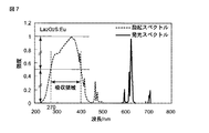
また、蛍光体はYAG:Ceに限定されるものではなく、ほかの適当な蛍光体、例えばCe賦活のCa3Sc2Si3O12などの蛍光体を使用してもよい。図3にCe賦活のCa3Sc2Si3O12のスペクトル特性を示す。図中、破線が吸収スペクトルで示し、実線が発光スペクトルを示している。図3に示す通り、このCe賦活のCa3Sc2Si3O12の吸収領域はおおよそ460nm〜530nmとなっている。従って、この蛍光体を用いるときは、これに応じて、第1の半導体レーザー22Aの励起光の波長を例えば500nm程度にすることによって、より効率的に励起光が波長変換されて明るい照明光が得られる。
The phosphor is not limited to YAG: Ce, and other suitable phosphors, for example, phosphors such as Ce-activated Ca 3 Sc 2 Si 3 O 12 may be used. FIG. 3 shows the spectral characteristics of Ce-activated Ca 3 Sc 2 Si 3 O 12 . In the figure, a broken line indicates an absorption spectrum, and a solid line indicates an emission spectrum. As shown in FIG. 3, the absorption region of the Ce activated Ca 3 Sc 2 Si 3 O 12 is approximately 460 nm to 530 nm. Therefore, when this phosphor is used, the wavelength of the excitation light of the
<第2実施形態>
次に、第2実施形態による光源装置について図4ないし図9を参照して説明する。第2実施形態では、第1実施形態と共通の部分については説明を省略し、主に異なる部分について説明する。
Second Embodiment
Next, a light source device according to a second embodiment will be described with reference to FIGS. In the second embodiment, description of parts common to the first embodiment is omitted, and different parts are mainly described.
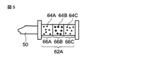
図4は、第2実施形態による光源装置を示している。図4に示すように、本実施形態による光源装置10Aは、第1実施形態による光源装置10との比較において、第1の光源部20Aの代わりに第3の光源部20Cを有し、光ファイバー30Aの代わりに光ファイバー30Cを有し、蛍光体ユニット62の代わりに蛍光体ユニット62Aを有している。第3の光源部20Cは、第3の半導体レーザー22Cと、第3の半導体レーザー22Cから発せられる発散性の光を収束させるレンズ24と、レンズ24により収束された光を光ファイバー30Cに光学的に結合する結合素子26とを有している。光源装置10Aはまた、駆動回路82Aの代わりに、第3の半導体レーザー22Cの発光・消灯すなわちオン・オフを独立に切り替える駆動回路82Cを有している。それ以外の構成は、第1実施形態と同様である。
FIG. 4 shows a light source device according to the second embodiment. As shown in FIG. 4, the
第3の半導体レーザー22Cは、波長375nmの近紫外光を発する。蛍光体ユニット62Aは、組成の異なる複数種類の蛍光体を含むマルチ蛍光体ユニットで構成されている。図5は、図4に示した蛍光体ユニット62Aを示している。図5に示すように、蛍光体ユニット62Aは、赤色光を発するR蛍光体64Aを含む領域66Aと、緑色光を発するG蛍光体64Bを含む領域66Bと、青色光を発するB蛍光体64Cを含む領域66Cとを入射端側から射出端側に順に積層して構成されたマルチ蛍光体ユニットで構成されている。これらの蛍光体64A,64B,64Cは、いずれも近紫外光である375nmの光により励起されて、それぞれ赤色光と緑色光と青色光を発するものが選択されている。このような蛍光体64A,64B,64Cは、たとえば、それぞれ、Eu賦活のLa2O2S(赤色)、Eu,Mn共賦活のBaMgAl10O17(緑色)、Eu賦活のBaMgAl10O17(青色)であってよい。Eu賦活のLa2O2S(赤色)の発光スペクトルを図7に、Eu,Mn共賦活のBaMgAl10O17(緑色)の発光スペクトルを図8に、Eu賦活のBaMgAl10O17(青色)の発光スペクトルを図9に示す。図7ないし図9に示す通り、これらの蛍光体の吸収領域は、それぞれ、270nm〜400nm、230nm〜400nm、270nm〜410nmである。これらの蛍光体を含むマルチ蛍光体ユニットの吸収領域は、すべての蛍光体の吸収領域の重なり領域とみなせ、270nm〜400nmである。
The
次に、第2実施形態による光源装置の動作について説明する。 Next, the operation of the light source device according to the second embodiment will be described.
第3の半導体レーザー22Cをオンにすると、第3の半導体レーザー22Cは波長375nmの近紫外のレーザー光を発する。第3の半導体レーザー22Cから発せられた近紫外レーザー光はレンズ24によって収束されて光ファイバー30Cに入射する。光ファイバー30Cに入射したレーザー光は光ファイバー30Cを導波し、光ファイバーカプラー42を経由し、光ファイバー50を導波して蛍光体ユニット62Aに入射する。蛍光体ユニット62Aは、図5に示すように、光ファイバー50と接続されている入射端側から順に、赤色光を発するR蛍光体64Aを含む領域66Aと、緑色光を発するG蛍光体64Bを含む領域66Bと、青色光を発するB蛍光体64Cを含む領域66Cとが配列されている。また、第3の半導体レーザー22Cの発する波長375nmの光は、蛍光体ユニット62Aを構成するマルチ蛍光体ユニットの吸収領域の光である。このため、領域66Aに入射した近紫外光の一部はR蛍光体64Aによって赤色光に波長変換されて領域66Bに入射し、領域66Aに入射した近紫外光の残りの一部はそのまま領域66Aを通過して領域66Bに入射する。領域66Bに入射した近紫外光の一部はG蛍光体64Bによって緑色光に波長変換されて領域66Cに入射する。また、G蛍光体64Bは赤色光を吸収しないので、領域66Bに入射した赤色光はそのまま領域66Bを通過する。従って、赤色光と緑色光と近紫外光とがB蛍光体64Cを含む領域66Cに入射する。領域66Cに入射した近紫外光のほとんどはB蛍光体64Cによって青色光に波長変換される。また、B蛍光体64Cは赤色光と緑色光を吸収しないので、領域66Cに入射した赤色光と緑色光はそのまま領域66Cを通過する。その結果、蛍光体ユニット62Aの射出端からは赤色光と緑色光と青色光とが混合された白色光が射出される。
When the
また、第2の半導体レーザー22Bをオンにすると、半導体レーザー22Bは波長415nmの青紫色のレーザー光を発する。第2の半導体レーザー22Bから発せられたレーザー光は、第1実施形態で説明したように、レンズ24によって収束されて光ファイバー30Bに入射し、光ファイバー30Bを導波し、光ファイバーカプラー42を経由し、光ファイバー50を導波して蛍光体ユニット62に入射する。波長415nmの青紫色光はマルチ蛍光体ユニットの吸収領域の光ではないので、蛍光体ユニット62Aに入射した青紫色光は、R蛍光体64AとG蛍光体64BとB蛍光体64Cのいずれにもほとんど吸収されず、蛍光体ユニット62Aをそのまま通過して射出端から射出される。
When the
この結果、光源装置10Aは、第3の半導体レーザー22Cが選択的にオンにされたときは白色光を射出し、第2の半導体レーザー22Bがオンにされたときは波長415nmの青紫光を射出する。光源装置10Aから射出される白色光は、赤色光と緑色光と青色光の成分を有するため、第1実施形態と比較して演色性の高い照明光となる。すなわち、本実施形態によれば、第1実施形態と同じ利点を有し、さらに演色性が向上した光源装置が得られる。
As a result, the
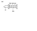
なお、本実施形態では、蛍光体ユニット62Aは、図5に示すように、R蛍光体64Aを含む領域66AとG蛍光体64Bを含む領域66BとB蛍光体64Cを含む領域66Cとが積層されたマルチ蛍光体ユニットで構成されているが、図6に示すように、それらの蛍光体64A,64B,64Cのすべてが混合された別のタイプのマルチ蛍光体ユニットで構成されてもよい。これにより、蛍光体ユニット62Aがシンプルに構成される。
In the present embodiment, as shown in FIG. 5, the
<第3実施形態>
次に、第3実施形態による光源装置について図10を参照して説明する。第3実施形態では、第1実施形態と共通の部分については説明を省略し、主に異なる部分について説明する。
<Third Embodiment>
Next, a light source device according to a third embodiment will be described with reference to FIG. In the third embodiment, description of parts common to the first embodiment is omitted, and different parts are mainly described.
図10は、第3実施形態による光源装置を示している。図10に示すように、本実施形態による光源装置10Bは、光カプラー40が2つの入射端と2つの射出端を有する2入力2出力タイプの光ファイバーカプラー42Aで構成されており、光ファイバーカプラー42Aの2つの射出端にそれぞれ2本の光ファイバー50と2つの蛍光体ユニット62とが接続されている点が第1実施形態と異なっている。
FIG. 10 shows a light source device according to the third embodiment. As shown in FIG. 10, in the light source device 10B according to the present embodiment, the
光ファイバーカプラー42Aは、2つの入射端と、2つの射出端とを有し、一方の入射端に入射した光を2つの射出端にほぼ等しい光強度割合で分配し、もう一方の入射端に入射した光を2つの射出端にほぼ等しい光強度割合で分配する。波長変換部60は、2つの蛍光体ユニット62を有している。2つの蛍光体ユニット62は、それぞれ、2本の光ファイバー50を介して光ファイバーカプラー42Aの2つの射出端と光学的に接続されている。2つの蛍光体ユニット62はほぼ等しい波長変換特性を有している。
The
第1の半導体レーザー22Aが発する波長460nmの青色光は光ファイバー30Aを導波して光ファイバーカプラー42Aに入射する。光ファイバーカプラー42Aに入射した青色光は、光ファイバーカプラー42Aによってほぼ等しい強度で2本の光ファイバー50に分配される。2本の光ファイバー50に分配された青色光は、それぞれ、2本の光ファイバー50を導波して2つの蛍光体ユニットに入射する。各蛍光体ユニットに入射した青色光は、第1実施形態で説明したように、青色光と波長変換された黄色光とが混合された白色光となり、各蛍光体ユニットから射出される。
The blue light having a wavelength of 460 nm emitted from the
また、第2の半導体レーザー22Bが発する波長415nmの青紫色光は光ファイバー30Bを導波して光ファイバーカプラー42Aに入射する。光ファイバーカプラー42Aに入射した青紫色光は、光ファイバーカプラー42Aによってほぼ等しい強度で2本の光ファイバー50に分配される。2本の光ファイバー50に分配された青紫色光は、それぞれ、2本の光ファイバー50を導波して2つの蛍光体ユニットに入射する。各蛍光体ユニットに入射した青紫色光は、第1実施形態で説明したように、そのまま各蛍光体ユニットから射出される。
Further, blue-violet light having a wavelength of 415 nm emitted from the
本実施形態によれば、第1実施形態の利点を有し、さらに観察対象を2方向から照明可能な光源装置が得られる。たとえば、内視鏡装置のように、観察対象から光源までが非常に近接しているとき、一方向だけからの照明は、影を生じさせるなど、観察対象物を見づらくすることがあるが、観察対象を2方向から照明するように2つの蛍光体ユニットの射出端を配置することによって、影を生じさせ難くすることが可能となる。この結果、大型化を伴うことなく、観察により適した光源装置が得られる。 According to this embodiment, the light source device that has the advantages of the first embodiment and can illuminate the observation target from two directions is obtained. For example, when the observation target and the light source are very close to each other as in an endoscopic device, illumination from only one direction may cause shadows, making it difficult to see the observation target. By arranging the emission ends of the two phosphor units so as to illuminate the object from two directions, it is possible to make it difficult to cause a shadow. As a result, a light source device more suitable for observation can be obtained without increasing the size.
本実施形態では、波長変換部60の各蛍光体ユニットが、第1実施形態で説明した蛍光体ユニット62で構成されているが、第2実施形態で説明したマルチ蛍光体ユニット62Aで構成されてもよい。さらに、光カプラー40を、3以上の出力端を有する光ファイバーカプラーに変更するとともに、光ファイバーカプラーの3以上の出力端に、それぞれ、光ファイバーカプラーの出力端と同数の光ファイバーと複数の蛍光体ユニットとを接続した構成としてもよい。
In this embodiment, each phosphor unit of the
<第4実施形態>
次に、第4実施形態による光源装置について説明する。本実施形態による光源装置は、基本的に第1実施形態と同様の構成を有しているが、波長変換部60が、励起波長特性の異なる2種類の蛍光体を含む蛍光体ユニットで構成されている点が第1実施形態と異なっている。
<Fourth embodiment>
Next, a light source device according to a fourth embodiment will be described. The light source device according to the present embodiment basically has the same configuration as that of the first embodiment, but the
本実施形態における蛍光体ユニット62は、第1の半導体レーザー22Aから発せられる青色レーザー光は波長変換するが、第2の半導体レーザー22Bから発せられる青紫色レーザー光はほとんど波長変換しない第1の蛍光体と、第1の半導体レーザーから発せられる青色レーザー光は波長変換しないが、第2の半導体レーザー22Bから発せられる青紫色レーザー光は波長変換する第2の蛍光体とを含む蛍光体ユニットで構成されている。
The
本実施形態においては、たとえば、第1の蛍光体はYAG:Ceで構成され、第2の蛍光体は、Eu賦活のSrAl2O4(以下、SrAlO:Euと記す)で構成されている。図2はYAG:Ceのスペクトル特性を示し、図11はSrAlO:Euのスペクトル特性を示している。第1の蛍光体であるYAG:Ceの吸収領域は430nm〜480nmであり、第2の蛍光体であるSrAlO:Euの吸収領域は270nm〜430nmである。 In the present embodiment, for example, the first phosphor is composed of YAG: Ce, and the second phosphor is composed of Eu-activated SrAl 2 O 4 (hereinafter referred to as SrAlO: Eu). FIG. 2 shows the spectral characteristics of YAG: Ce, and FIG. 11 shows the spectral characteristics of SrAlO: Eu. The absorption region of YAG: Ce that is the first phosphor is 430 nm to 480 nm, and the absorption region of SrAlO: Eu that is the second phosphor is 270 nm to 430 nm.
この第4実施形態の動作について説明する。 The operation of the fourth embodiment will be described.
始めに第1の半導体レーザー22Aをオンにしたときの動作について説明する。第1の半導体レーザー22Aは、第1実施形態で説明したように、460nmの波長の青色レーザー光を発する。第1の半導体レーザー22Aから発せられたレーザー光は、光ファイバー30Aを導波し、光ファイバーカプラー42を経由し、光ファイバー50を導波して蛍光体ユニット62に入射する。蛍光体ユニット62は、図2に示した特性を有するYAG:Ceと、図11に示した特性を有するSrAlO:Euとを含んでおり、また、波長460nmの青色光は、YAG:Ceの吸収領域内にあり、かつ、SrAlO:Euの吸収領域外にある光であるため、蛍光体ユニット62に入射した青色光は、YAG:Ceによって効率的に波長530nm程度の黄色光に波長変換されるが、SrAlO:Euによってはほとんど波長変換されない。その結果、蛍光体ユニット62の射出端からは、青色光とYAG:Ceにより波長変換された黄色光とが混合された白色光が射出される。
First, an operation when the
次に、第2の半導体レーザー22Bをオンにしたときの動作について説明する。第2の半導体レーザー22Bは、第1実施形態で説明したように、波長415nmの青紫色レーザー光を発する。第2の半導体レーザー22Bから発せられたレーザー光は、光ファイバー30Bを導波し、光ファイバーカプラー42を経由し、光ファイバー50を導波して蛍光体ユニット62に入射する。波長415nmの青紫色光は、SrAlO:Euの吸収領域内にあり、かつ、YAG:Ceの吸収領域外にある光であるため、蛍光体ユニット62に入射した青紫色光は、YAG:Ceによってはほとんど波長変換されないが、SrAlO:Euによって波長540nm程度の緑色光に効率的に波長変換される。その結果、蛍光体ユニット62の射出端からは、図12に示すように、波長415nmの青紫色光と波長540nmの緑色光とが混合された光が射出される。この2つの波長の光は、ヘモグロビンの吸収波長とほぼ一致しており、血管をよりコントラスト良く観察することに好適である。
Next, an operation when the
本実施形態によれば、第1実施形態の利点を有し、さらに血管などをよりコントラスト良く観察することに適した光源装置が得られる。この光源装置は、蛍光体ユニット62に含まれる蛍光体の種類が増えるだけであり、他に大きな変更を必要としないため、装置の大型化を伴わない。
According to the present embodiment, a light source device that has the advantages of the first embodiment and is suitable for observing blood vessels and the like with higher contrast can be obtained. In this light source device, only the types of phosphors included in the
<付記>
上述したすべての実施形態では、光源が半導体レーザーで構成されているが、光源は、これに限定されるものではなく、発光ダイオードなどの他の半導体光源で構成されてもよい。発光ダイオードを使用すると、半導体レーザーを使用したときと比較して、より安価な光源装置が得られる。
<Appendix>
In all the embodiments described above, the light source is configured by a semiconductor laser, but the light source is not limited to this, and may be configured by another semiconductor light source such as a light emitting diode. When a light emitting diode is used, a cheaper light source device can be obtained as compared with the case where a semiconductor laser is used.
また、上述した実施形態の光源装置は特に内視鏡装置への搭載に適している。 In addition, the light source device of the above-described embodiment is particularly suitable for mounting on an endoscope apparatus.
一般的な内視鏡装置を図13に概略的に示す。図13に示すように、内視鏡装置100は、操作部110と、操作部110から延びている挿入部120と、挿入部120の先端に位置する内視鏡先端部130とを有している。このような内視鏡装置100を用いた観察では、観察対象が内視鏡先端部130に近接するため、通常観察光と特殊光の射出位置がずれていると、色分離を起こすなどの不具合が生じる。これに対して上述した実施形態の光源装置では、通常観察光と特殊光の射出位置が一致しているので、色分離を起こすことがなく、特に内視鏡装置への搭載に適している。
A general endoscope apparatus is schematically shown in FIG. As shown in FIG. 13, the
また、一般的な内視鏡先端部130の構成を図14に示す。図14に示すように、内視鏡先端部130は、3つの先端金属部材132A,132B,132Cと、それらを覆うカバー144とを有している。2つの先端金属部材132A,132Cは断熱材134Aを介して結合され、2つの先端金属部材132B,132Cは断熱材134Bを介して結合されている。先端金属部材132Cには個体撮像装置136と送気送水ノズル138と吸引チャンネル140とが設けられている。また先端金属部材132A,132Bには照明用のライトガイドユニット142が1つずつ設けられている。
Further, FIG. 14 shows a configuration of a general endoscope
このように内視鏡装置は一般に2つのライトガイドユニット142を有している。このため、上述した実施形態の光源装置を内視鏡装置に搭載する際は、図1や図4に示したように1つの光射出部を有する光源装置を2つ内視鏡装置に組み込んでもよく、また図10に示したように2つの光射出部を有する光源装置を1つだけ内視鏡装置に組み込んでもよい。
Thus, the endoscope apparatus generally has two
さらに、上述した実施形態の光源装置を内視鏡装置に搭載する際、内視鏡先端部130の近傍に波長変換部60を配置してもよく、また、波長変換部60から射出される光を再び別の光ファイバーを介して内視鏡先端部130まで導いてもよい。前者の構成は、高い輝度の照明光を得るのに都合が良い。また後者の構成は、発熱する蛍光体ユニットが内視鏡先端部から離して配置されるため、内視鏡先端部の近傍の発熱を抑制するのに都合が良い。
Furthermore, when the light source device of the above-described embodiment is mounted on an endoscope apparatus, the
これまで、図面を参照しながら本発明の実施形態を述べたが、本発明は、これらの実施形態に限定されるものではなく、その要旨を逸脱しない範囲において様々な変形や変更が施されてもよい。 The embodiments of the present invention have been described above with reference to the drawings. However, the present invention is not limited to these embodiments, and various modifications and changes can be made without departing from the scope of the present invention. Also good.
10,10A,10B…光源装置、20A,20B,20C…光源部、22A,22B,22C…半導体レーザー、24…レンズ、26…結合素子、30A,30B,30C…光ファイバー、40…光ファイバーカプラー、42,42A…光ファイバーカプラー、50…光ファイバー、60…波長変換部、62,62A…蛍光体ユニット、64A…R蛍光体、64B…G蛍光体、64C…B蛍光体、66A,66B,66C…領域、82A,82B,82C…駆動回路、100…内視鏡装置、110…操作部、120…挿入部、130…内視鏡先端部、132A,132B,132C…先端金属部材、134A,134B…断熱材、136…個体撮像装置、138…送気送水ノズル、140…吸引チャンネル、142…ライトガイドユニット、144…カバー。
DESCRIPTION OF
Claims (13)
前記第1の波長領域と異なる前記第2の波長領域の光を発する第2の半導体光源と、
前記第1の波長領域の光を吸収して前記第1および第2の波長領域のいずれとも異なる第3の波長領域の光を発し、かつ、前記第2の波長領域の光をほとんど透過する波長変換部とを有している光源装置。 A first semiconductor light source that emits light in a first wavelength region;
A second semiconductor light source that emits light in the second wavelength region different from the first wavelength region;
A wavelength that absorbs light in the first wavelength region, emits light in a third wavelength region that is different from both the first and second wavelength regions, and transmits almost the light in the second wavelength region. A light source device having a conversion unit.
Priority Applications (9)
| Application Number | Priority Date | Filing Date | Title |
|---|---|---|---|
| JP2007335321A JP2009153712A (en) | 2007-12-26 | 2007-12-26 | Light source device and endoscope apparatus comprising the same |
| US12/335,833 US8698387B2 (en) | 2007-12-26 | 2008-12-16 | Light source device and endoscope apparatus comprising the same |
| EP08171890A EP2074934A3 (en) | 2007-12-26 | 2008-12-17 | Light source device and endoscope apparatus comprising the same |
| US13/909,554 US8810126B2 (en) | 2007-12-26 | 2013-06-04 | Light source device and endoscope apparatus comprising the same |
| US14/293,551 US9303830B2 (en) | 2007-12-26 | 2014-06-02 | Light source device and endoscope apparatus comprising the same |
| US14/293,587 US9217545B2 (en) | 2007-12-26 | 2014-06-02 | Light source device and endoscope apparatus comprising the same |
| US15/051,104 US9587791B2 (en) | 2007-12-26 | 2016-02-23 | Light source device and endoscope apparatus comprising the same |
| US15/393,024 US10156324B2 (en) | 2007-12-26 | 2016-12-28 | Light source device and endoscope apparatus comprising the same |
| US16/184,204 US10801677B2 (en) | 2007-12-26 | 2018-11-08 | Light source device and endoscope apparatus comprising the same |
Applications Claiming Priority (1)
| Application Number | Priority Date | Filing Date | Title |
|---|---|---|---|
| JP2007335321A JP2009153712A (en) | 2007-12-26 | 2007-12-26 | Light source device and endoscope apparatus comprising the same |
Related Child Applications (5)
| Application Number | Title | Priority Date | Filing Date |
|---|---|---|---|
| JP2013055464A Division JP5718398B2 (en) | 2013-03-18 | 2013-03-18 | Endoscope device |
| JP2013055467A Division JP5698782B2 (en) | 2013-03-18 | 2013-03-18 | LIGHT SOURCE DEVICE AND ENDOSCOPE DEVICE EQUIPPED WITH THE SAME |
| JP2013055463A Division JP5698779B2 (en) | 2013-03-18 | 2013-03-18 | Endoscope apparatus having light source device |
| JP2013055465A Division JP5698780B2 (en) | 2013-03-18 | 2013-03-18 | LIGHT SOURCE DEVICE AND ENDOSCOPE DEVICE EQUIPPED WITH THE SAME |
| JP2013055466A Division JP5698781B2 (en) | 2013-03-18 | 2013-03-18 | LIGHT SOURCE DEVICE AND ENDOSCOPE DEVICE EQUIPPED WITH THE SAME |
Publications (2)
| Publication Number | Publication Date |
|---|---|
| JP2009153712A true JP2009153712A (en) | 2009-07-16 |
| JP2009153712A5 JP2009153712A5 (en) | 2011-02-10 |
Family
ID=40403984
Family Applications (1)
| Application Number | Title | Priority Date | Filing Date |
|---|---|---|---|
| JP2007335321A Pending JP2009153712A (en) | 2007-12-26 | 2007-12-26 | Light source device and endoscope apparatus comprising the same |
Country Status (3)
| Country | Link |
|---|---|
| US (7) | US8698387B2 (en) |
| EP (1) | EP2074934A3 (en) |
| JP (1) | JP2009153712A (en) |
Cited By (33)
| Publication number | Priority date | Publication date | Assignee | Title |
|---|---|---|---|---|
| JP2011010998A (en) * | 2009-07-06 | 2011-01-20 | Fujifilm Corp | Lighting device for endoscope and endoscope apparatus |
| JP2011036361A (en) * | 2009-08-10 | 2011-02-24 | Fujifilm Corp | Endoscopic device |
| JP2011050470A (en) * | 2009-08-31 | 2011-03-17 | Fujifilm Corp | Endoscope system |
| JP2011067266A (en) * | 2009-09-24 | 2011-04-07 | Fujifilm Corp | Endoscope apparatus |
| JP2011072424A (en) * | 2009-09-29 | 2011-04-14 | Fujifilm Corp | Projector unit, medical apparatus mounting the same, and endoscope apparatus |
| WO2011048867A1 (en) * | 2009-10-21 | 2011-04-28 | オリンパス株式会社 | Light source device, electronic image acquisition apparatus, electronic image observation apparatus, endoscope apparatus, and capsule endoscope apparatus |
| JP2011087910A (en) * | 2009-09-24 | 2011-05-06 | Fujifilm Corp | Endoscope system |
| JP2011092683A (en) * | 2009-09-29 | 2011-05-12 | Fujifilm Corp | Electronic endoscope |
| JP2011098089A (en) * | 2009-11-06 | 2011-05-19 | Fujifilm Corp | Electronic endoscope system, processor device for electronic endoscope, and signal separating method |
| JP2011206226A (en) * | 2010-03-29 | 2011-10-20 | Fujifilm Corp | Endoscopic system |
| JP2012005807A (en) * | 2009-09-24 | 2012-01-12 | Fujifilm Corp | Method of controlling endoscope apparatus and endoscope apparatus |
| JP2012016545A (en) * | 2010-07-09 | 2012-01-26 | Fujifilm Corp | Endoscope apparatus |
| JP2012029703A (en) * | 2009-09-24 | 2012-02-16 | Fujifilm Corp | Method for controlling endoscope apparatus, and endoscope apparatus |
| JP2013128785A (en) * | 2013-03-18 | 2013-07-04 | Olympus Corp | Endoscope device |
| JP2013128786A (en) * | 2013-03-18 | 2013-07-04 | Olympus Corp | Light source device and endoscope device including the same |
| JP2013135933A (en) * | 2013-03-18 | 2013-07-11 | Olympus Corp | Light source device and endoscope having the same |
| JP2014121630A (en) * | 2014-02-10 | 2014-07-03 | Fujifilm Corp | Endoscope device |
| WO2014119546A1 (en) * | 2013-01-29 | 2014-08-07 | オリンパス株式会社 | Light source device, subject observation device and light source control method |
| WO2014136706A1 (en) * | 2013-03-06 | 2014-09-12 | オリンパス株式会社 | Subject observation system and method |
| JP2015037609A (en) * | 2014-11-10 | 2015-02-26 | 富士フイルム株式会社 | Endoscopic apparatus |
| JP2015091351A (en) * | 2014-12-24 | 2015-05-14 | 富士フイルム株式会社 | Endoscope device |
| US9217545B2 (en) | 2007-12-26 | 2015-12-22 | Olympus Corporation | Light source device and endoscope apparatus comprising the same |
| JP2016137308A (en) * | 2016-04-13 | 2016-08-04 | 富士フイルム株式会社 | Endoscopic apparatus |
| JP2016202582A (en) * | 2015-04-22 | 2016-12-08 | パナソニック株式会社 | Endoscope |
| JP2017087078A (en) * | 2017-02-28 | 2017-05-25 | 富士フイルム株式会社 | Endoscope apparatus |
| US9675238B2 (en) | 2011-08-10 | 2017-06-13 | Fujifilm Corporation | Endoscopic device |
| JP2017522074A (en) * | 2014-06-04 | 2017-08-10 | ジャイラス・エーシーエムアイ・インコーポレーテッド | Illumination balancing and solid-state narrowband imaging using fiber bundle design and assembly techniques within an endoscope |
| JP2017209530A (en) * | 2017-08-29 | 2017-11-30 | 富士フイルム株式会社 | Light source device for endoscopes and endoscope system |
| WO2018008283A1 (en) | 2016-07-04 | 2018-01-11 | パナソニックIpマネジメント株式会社 | Fiber light source, endoscope, and endoscope system |
| JP6450492B1 (en) * | 2018-07-19 | 2019-01-09 | パナソニック株式会社 | Endoscopic illumination device and endoscope system |
| US10714661B2 (en) | 2016-07-04 | 2020-07-14 | Panasonic Intellectual Property Management Co., Ltd. | Light-emitting apparatus including phosphor |
| WO2020162243A1 (en) * | 2019-02-04 | 2020-08-13 | パナソニックIpマネジメント株式会社 | Light emitting device and medical device using same |
| US11036120B2 (en) | 2016-07-04 | 2021-06-15 | Panasonic Intellectual Property Management Co., Ltd. | Projector including phosphor |
Families Citing this family (40)
| Publication number | Priority date | Publication date | Assignee | Title |
|---|---|---|---|---|
| US8435276B2 (en) * | 2006-02-27 | 2013-05-07 | Thomas Perez | Method and apparatus for the combined application of light therapy, optic diagnosis, and fluid to tissue |
| JP5117878B2 (en) * | 2008-02-13 | 2013-01-16 | 富士フイルム株式会社 | Endoscope light source device |
| DE602009001103D1 (en) * | 2008-06-04 | 2011-06-01 | Fujifilm Corp | Lighting device for use in endoscopes |
| JP5216429B2 (en) * | 2008-06-13 | 2013-06-19 | 富士フイルム株式会社 | Light source device and endoscope device |
| WO2010006275A1 (en) * | 2008-07-10 | 2010-01-14 | Corporation For Laser Optics Research | Blue laser pumped green light source for displays |
| WO2010050426A1 (en) * | 2008-10-27 | 2010-05-06 | オリンパスメディカルシステムズ株式会社 | In vivo insertion device and medical system |
| US8734333B2 (en) * | 2009-03-18 | 2014-05-27 | Fujifilm Corporation | Endoscope system, endoscope video processor and method of driving endoscope system |
| CN102469913A (en) * | 2009-07-23 | 2012-05-23 | 奥林巴斯医疗株式会社 | Transmissivity-adjusting device, observation device and observation system |
| JP2011147757A (en) * | 2009-09-29 | 2011-08-04 | Fujifilm Corp | Medical apparatus and endoscope apparatus |
| JP5258869B2 (en) * | 2010-12-13 | 2013-08-07 | 富士フイルム株式会社 | Endoscope device |
| JP5554253B2 (en) * | 2011-01-27 | 2014-07-23 | 富士フイルム株式会社 | Electronic endoscope system |
| WO2012133632A1 (en) * | 2011-03-30 | 2012-10-04 | オリンパス株式会社 | Light source unit, optical conversion unit, light source device, and light source system |
| JP5485215B2 (en) * | 2011-04-01 | 2014-05-07 | 富士フイルム株式会社 | Endoscope device |
| JP5331904B2 (en) * | 2011-04-15 | 2013-10-30 | 富士フイルム株式会社 | Endoscope system and method for operating endoscope system |
| JP5851140B2 (en) * | 2011-07-28 | 2016-02-03 | オリンパス株式会社 | Light source device |
| JP5303015B2 (en) * | 2011-08-29 | 2013-10-02 | 富士フイルム株式会社 | Endoscopic diagnosis device |
| JP5830340B2 (en) * | 2011-10-11 | 2015-12-09 | オリンパス株式会社 | Light source device |
| US20140052004A1 (en) * | 2012-08-15 | 2014-02-20 | Arthrex, Inc. | Endoscopic camera illumination system and method |
| JP6412709B2 (en) * | 2014-04-02 | 2018-10-24 | オリンパス株式会社 | Observation image acquisition system |
| FR3019625B1 (en) * | 2014-04-04 | 2018-10-26 | Maquet Sas | OPERATIVE LIGHTING APPARATUS WITH LASER SOURCE DEPORTEE |
| DE102014210492A1 (en) | 2014-06-03 | 2015-12-03 | Osram Gmbh | Conversion device for converting radiation of an excitation radiation source into conversion radiation and method for producing such a conversion device |
| JP6201904B2 (en) * | 2014-06-10 | 2017-09-27 | 豊田合成株式会社 | Light emitting device |
| WO2016037773A2 (en) | 2014-09-11 | 2016-03-17 | Philips Lighting Holding B.V. | Pc-led module with enhanced white rendering and conversion efficiency. |
| US10488018B2 (en) | 2015-08-17 | 2019-11-26 | Infinite Arthroscopy, Inc. Limited | Light source |
| WO2017087448A1 (en) | 2015-11-16 | 2017-05-26 | Infinite Arthroscopy Inc, Limited | Wireless medical imaging system |
| GB2546329A (en) * | 2016-01-15 | 2017-07-19 | Barco Nv | System and method for endoscope calibration |
| JP2016105824A (en) * | 2016-02-08 | 2016-06-16 | 富士フイルム株式会社 | Endoscope apparatus |
| WO2017141417A1 (en) | 2016-02-19 | 2017-08-24 | Hoya株式会社 | Endoscope light source device |
| JPWO2017175391A1 (en) * | 2016-04-08 | 2019-03-28 | オリンパス株式会社 | Illuminating device and endoscope provided with the same |
| JP6155367B2 (en) * | 2016-06-17 | 2017-06-28 | 富士フイルム株式会社 | Endoscope device |
| EP3480281A4 (en) | 2016-07-04 | 2019-07-31 | Panasonic Intellectual Property Management Co., Ltd. | Fluorescent substance and light-emitting device |
| CN109068968B (en) * | 2016-09-16 | 2021-02-05 | 奥林巴斯株式会社 | Light source device for endoscope |
| JP6944104B2 (en) * | 2016-11-30 | 2021-10-06 | 日亜化学工業株式会社 | Light emitting device |
| EP3582676B1 (en) | 2017-02-15 | 2023-08-16 | Lazurite Holdings LLC | Wireless medical imaging system comprising a head unit and a light cable that comprises an integrated light source |
| JP6550420B2 (en) * | 2017-06-02 | 2019-07-24 | 富士フイルム株式会社 | Endoscope device |
| JP2017200601A (en) * | 2017-07-04 | 2017-11-09 | 富士フイルム株式会社 | Endoscope apparatus |
| JP6379260B2 (en) * | 2017-07-04 | 2018-08-22 | 富士フイルム株式会社 | Endoscope device |
| US11228157B2 (en) * | 2019-05-24 | 2022-01-18 | Fraen Corporation | CRI-booster white laser fiber source |
| USD938584S1 (en) | 2020-03-30 | 2021-12-14 | Lazurite Holdings Llc | Hand piece |
| USD972176S1 (en) | 2020-08-06 | 2022-12-06 | Lazurite Holdings Llc | Light source |
Citations (3)
| Publication number | Priority date | Publication date | Assignee | Title |
|---|---|---|---|---|
| JP2006061685A (en) * | 2004-07-28 | 2006-03-09 | Kyocera Corp | Light source apparatus and endoscope equipped with light source apparatus |
| JP2006296656A (en) * | 2005-04-19 | 2006-11-02 | Fuji Photo Film Co Ltd | Endoscope apparatus |
| JP2006314686A (en) * | 2005-05-16 | 2006-11-24 | Olympus Medical Systems Corp | Endoscope |
Family Cites Families (49)
| Publication number | Priority date | Publication date | Assignee | Title |
|---|---|---|---|---|
| JPH07155291A (en) | 1993-12-03 | 1995-06-20 | Olympus Optical Co Ltd | Fluorescence observation apparatus |
| TW383508B (en) | 1996-07-29 | 2000-03-01 | Nichia Kagaku Kogyo Kk | Light emitting device and display |
| JP3868050B2 (en) | 1997-02-06 | 2007-01-17 | オリンパス株式会社 | Endoscope |
| EP1029167A1 (en) | 1997-10-28 | 2000-08-23 | Rudi Beichel | An advanced technology pollution free, highly efficient industrial power generation system |
| JP3586157B2 (en) | 1999-12-20 | 2004-11-10 | オリンパス株式会社 | Subject observation device |
| CA2297476A1 (en) | 2000-01-21 | 2001-07-21 | Neks Recherche & Developpement Inc. | System for detection of dental tartar, e.g. subgingival tartar |
| US6577073B2 (en) * | 2000-05-31 | 2003-06-10 | Matsushita Electric Industrial Co., Ltd. | Led lamp |
| JP3607857B2 (en) | 2000-07-27 | 2005-01-05 | オリンパス株式会社 | Endoscope device |
| US7892169B2 (en) | 2000-07-21 | 2011-02-22 | Olympus Corporation | Endoscope apparatus |
| DE10109850A1 (en) * | 2001-03-01 | 2002-09-05 | Wavelight Laser Technologie Ag | Device for generating white light |
| JP4390096B2 (en) | 2001-07-06 | 2009-12-24 | 富士フイルム株式会社 | Endoscope device |
| US6921920B2 (en) | 2001-08-31 | 2005-07-26 | Smith & Nephew, Inc. | Solid-state light source |
| JP3699040B2 (en) | 2001-11-22 | 2005-09-28 | オリンパス株式会社 | Electronic endoscope |
| ES2406697T3 (en) | 2002-03-12 | 2013-06-07 | Beth Israel Deaconess Medical Center | Medical imaging system |
| CN1493250A (en) | 2002-10-31 | 2004-05-05 | ƽ | Device using endoscope to diagnose precancer affection |
| JP4274843B2 (en) * | 2003-04-21 | 2009-06-10 | シャープ株式会社 | LED device and mobile phone device, digital camera and LCD display device using the same |
| KR100691143B1 (en) * | 2003-04-30 | 2007-03-09 | 삼성전기주식회사 | Light emitting diode device with multi-layered phosphor |
| US20050006659A1 (en) | 2003-07-09 | 2005-01-13 | Ng Kee Yean | Light emitting diode utilizing a discrete wavelength-converting layer for color conversion |
| JP2005039126A (en) | 2003-07-17 | 2005-02-10 | Sumitomo Electric Ind Ltd | Wide-band light source |
| JP4485471B2 (en) | 2003-11-19 | 2010-06-23 | リチャード ウルフ ゲーエムベーハー | Image providing device for tissue diagnosis |
| JP4554944B2 (en) | 2004-01-15 | 2010-09-29 | Hoya株式会社 | Endoscope device |
| TWI303751B (en) | 2004-03-16 | 2008-12-01 | Imec Inter Uni Micro Electr | Method of manufacturing a semiconductor device |
| JP4317478B2 (en) | 2004-03-31 | 2009-08-19 | 三菱化学株式会社 | Phosphor-type light emitting device and endoscope device using the same as an illumination source |
| JP4481751B2 (en) | 2004-07-09 | 2010-06-16 | Hoya株式会社 | The tip of the autofluorescence endoscope |
| JP4589670B2 (en) | 2004-07-16 | 2010-12-01 | Hoya株式会社 | Endoscope light source device |
| US20080262316A1 (en) * | 2004-07-28 | 2008-10-23 | Kyocera Corporation | Light Source Apparatus and Endoscope Provided with Light Source Apparatus |
| US7311858B2 (en) * | 2004-08-04 | 2007-12-25 | Intematix Corporation | Silicate-based yellow-green phosphors |
| JP5081370B2 (en) * | 2004-08-31 | 2012-11-28 | 日亜化学工業株式会社 | Light emitting device |
| WO2006038502A1 (en) | 2004-10-01 | 2006-04-13 | Nichia Corporation | Light-emitting device |
| US7433115B2 (en) | 2004-12-15 | 2008-10-07 | Nichia Corporation | Light emitting device |
| JP2006173324A (en) | 2004-12-15 | 2006-06-29 | Nichia Chem Ind Ltd | Light emitting device |
| JP4729918B2 (en) | 2004-12-17 | 2011-07-20 | 日亜化学工業株式会社 | Light emitting device |
| JP4794916B2 (en) | 2005-06-16 | 2011-10-19 | オリンパスメディカルシステムズ株式会社 | Endoscope and endoscope system |
| US7621653B2 (en) * | 2005-11-22 | 2009-11-24 | Xenopus Electronix, Llc | Multi-function illumination device |
| KR100771811B1 (en) * | 2005-12-27 | 2007-10-30 | 삼성전기주식회사 | White light emitting device |
| JP4793684B2 (en) | 2006-03-23 | 2011-10-12 | 日亜化学工業株式会社 | Light emitting device |
| JP4740036B2 (en) | 2006-05-26 | 2011-08-03 | 積水化学工業株式会社 | Method for measuring hemoglobins |
| US7618176B2 (en) * | 2006-06-22 | 2009-11-17 | Avago Technologies General Ip (Singapore) Pte. Ltd. | Solid state light source adapted for remote illumination |
| US20080192458A1 (en) * | 2007-02-12 | 2008-08-14 | Intematix Corporation | Light emitting diode lighting system |
| JP4017015B2 (en) | 2007-02-13 | 2007-12-05 | 日亜化学工業株式会社 | Light emitting device |
| JP5214193B2 (en) | 2007-08-10 | 2013-06-19 | オリンパス株式会社 | Fiber light source |
| JP2009039438A (en) * | 2007-08-10 | 2009-02-26 | Olympus Corp | Optical fiber lighting system |
| JP2009153712A (en) | 2007-12-26 | 2009-07-16 | Olympus Corp | Light source device and endoscope apparatus comprising the same |
| JP5401205B2 (en) | 2009-08-10 | 2014-01-29 | 富士フイルム株式会社 | Endoscope device |
| JP5698780B2 (en) | 2013-03-18 | 2015-04-08 | オリンパス株式会社 | LIGHT SOURCE DEVICE AND ENDOSCOPE DEVICE EQUIPPED WITH THE SAME |
| JP5698781B2 (en) | 2013-03-18 | 2015-04-08 | オリンパス株式会社 | LIGHT SOURCE DEVICE AND ENDOSCOPE DEVICE EQUIPPED WITH THE SAME |
| JP5698779B2 (en) | 2013-03-18 | 2015-04-08 | オリンパス株式会社 | Endoscope apparatus having light source device |
| JP5698782B2 (en) | 2013-03-18 | 2015-04-08 | オリンパス株式会社 | LIGHT SOURCE DEVICE AND ENDOSCOPE DEVICE EQUIPPED WITH THE SAME |
| JP5718398B2 (en) | 2013-03-18 | 2015-05-13 | オリンパス株式会社 | Endoscope device |
-
2007
- 2007-12-26 JP JP2007335321A patent/JP2009153712A/en active Pending
-
2008
- 2008-12-16 US US12/335,833 patent/US8698387B2/en active Active
- 2008-12-17 EP EP08171890A patent/EP2074934A3/en not_active Withdrawn
-
2013
- 2013-06-04 US US13/909,554 patent/US8810126B2/en active Active
-
2014
- 2014-06-02 US US14/293,551 patent/US9303830B2/en active Active
- 2014-06-02 US US14/293,587 patent/US9217545B2/en active Active
-
2016
- 2016-02-23 US US15/051,104 patent/US9587791B2/en active Active
- 2016-12-28 US US15/393,024 patent/US10156324B2/en active Active
-
2018
- 2018-11-08 US US16/184,204 patent/US10801677B2/en active Active
Patent Citations (3)
| Publication number | Priority date | Publication date | Assignee | Title |
|---|---|---|---|---|
| JP2006061685A (en) * | 2004-07-28 | 2006-03-09 | Kyocera Corp | Light source apparatus and endoscope equipped with light source apparatus |
| JP2006296656A (en) * | 2005-04-19 | 2006-11-02 | Fuji Photo Film Co Ltd | Endoscope apparatus |
| JP2006314686A (en) * | 2005-05-16 | 2006-11-24 | Olympus Medical Systems Corp | Endoscope |
Cited By (49)
| Publication number | Priority date | Publication date | Assignee | Title |
|---|---|---|---|---|
| US10156324B2 (en) | 2007-12-26 | 2018-12-18 | Olympus Corporation | Light source device and endoscope apparatus comprising the same |
| US9217545B2 (en) | 2007-12-26 | 2015-12-22 | Olympus Corporation | Light source device and endoscope apparatus comprising the same |
| US9303830B2 (en) | 2007-12-26 | 2016-04-05 | Olympus Corporation | Light source device and endoscope apparatus comprising the same |
| US9587791B2 (en) | 2007-12-26 | 2017-03-07 | Olympus Corporation | Light source device and endoscope apparatus comprising the same |
| US10801677B2 (en) | 2007-12-26 | 2020-10-13 | Olympus Corporation | Light source device and endoscope apparatus comprising the same |
| US8858429B2 (en) | 2009-07-06 | 2014-10-14 | Fujifilm Corporation | Lighting device for endoscope and endoscope device |
| JP2011010998A (en) * | 2009-07-06 | 2011-01-20 | Fujifilm Corp | Lighting device for endoscope and endoscope apparatus |
| JP2011036361A (en) * | 2009-08-10 | 2011-02-24 | Fujifilm Corp | Endoscopic device |
| JP2011050470A (en) * | 2009-08-31 | 2011-03-17 | Fujifilm Corp | Endoscope system |
| JP2011087910A (en) * | 2009-09-24 | 2011-05-06 | Fujifilm Corp | Endoscope system |
| JP2011067266A (en) * | 2009-09-24 | 2011-04-07 | Fujifilm Corp | Endoscope apparatus |
| US8624966B2 (en) | 2009-09-24 | 2014-01-07 | Fujifilm Corporation | Endoscope apparatus calibration with color correction table |
| JP2012005807A (en) * | 2009-09-24 | 2012-01-12 | Fujifilm Corp | Method of controlling endoscope apparatus and endoscope apparatus |
| JP2012029703A (en) * | 2009-09-24 | 2012-02-16 | Fujifilm Corp | Method for controlling endoscope apparatus, and endoscope apparatus |
| JP2011072424A (en) * | 2009-09-29 | 2011-04-14 | Fujifilm Corp | Projector unit, medical apparatus mounting the same, and endoscope apparatus |
| JP2011092683A (en) * | 2009-09-29 | 2011-05-12 | Fujifilm Corp | Electronic endoscope |
| WO2011048867A1 (en) * | 2009-10-21 | 2011-04-28 | オリンパス株式会社 | Light source device, electronic image acquisition apparatus, electronic image observation apparatus, endoscope apparatus, and capsule endoscope apparatus |
| JP2011091158A (en) * | 2009-10-21 | 2011-05-06 | Olympus Corp | Light source device, electronic image acquisition device, electronic image observation device, endoscope device, and capsule endoscope device |
| US9332895B2 (en) | 2009-10-21 | 2016-05-10 | Olympus Corporation | Light irradiating apparatus |
| JP2011098089A (en) * | 2009-11-06 | 2011-05-19 | Fujifilm Corp | Electronic endoscope system, processor device for electronic endoscope, and signal separating method |
| US9232883B2 (en) | 2010-03-29 | 2016-01-12 | Fujifilm Corporation | Endoscope apparatus |
| JP2011206226A (en) * | 2010-03-29 | 2011-10-20 | Fujifilm Corp | Endoscopic system |
| JP2012016545A (en) * | 2010-07-09 | 2012-01-26 | Fujifilm Corp | Endoscope apparatus |
| US9675238B2 (en) | 2011-08-10 | 2017-06-13 | Fujifilm Corporation | Endoscopic device |
| US9814375B2 (en) | 2013-01-29 | 2017-11-14 | Olympus Corporation | Light source device and subject observation apparatus as well as light source control method |
| JP2014144144A (en) * | 2013-01-29 | 2014-08-14 | Olympus Corp | Light source device, specimen observation apparatus and light source control method |
| WO2014119546A1 (en) * | 2013-01-29 | 2014-08-07 | オリンパス株式会社 | Light source device, subject observation device and light source control method |
| JP2014171511A (en) * | 2013-03-06 | 2014-09-22 | Olympus Corp | Subject observation system and method thereof |
| WO2014136706A1 (en) * | 2013-03-06 | 2014-09-12 | オリンパス株式会社 | Subject observation system and method |
| JP2013128786A (en) * | 2013-03-18 | 2013-07-04 | Olympus Corp | Light source device and endoscope device including the same |
| JP2013128785A (en) * | 2013-03-18 | 2013-07-04 | Olympus Corp | Endoscope device |
| JP2013135933A (en) * | 2013-03-18 | 2013-07-11 | Olympus Corp | Light source device and endoscope having the same |
| JP2014121630A (en) * | 2014-02-10 | 2014-07-03 | Fujifilm Corp | Endoscope device |
| JP2017522074A (en) * | 2014-06-04 | 2017-08-10 | ジャイラス・エーシーエムアイ・インコーポレーテッド | Illumination balancing and solid-state narrowband imaging using fiber bundle design and assembly techniques within an endoscope |
| JP2015037609A (en) * | 2014-11-10 | 2015-02-26 | 富士フイルム株式会社 | Endoscopic apparatus |
| JP2015091351A (en) * | 2014-12-24 | 2015-05-14 | 富士フイルム株式会社 | Endoscope device |
| JP2016202582A (en) * | 2015-04-22 | 2016-12-08 | パナソニック株式会社 | Endoscope |
| JP2016137308A (en) * | 2016-04-13 | 2016-08-04 | 富士フイルム株式会社 | Endoscopic apparatus |
| WO2018008283A1 (en) | 2016-07-04 | 2018-01-11 | パナソニックIpマネジメント株式会社 | Fiber light source, endoscope, and endoscope system |
| US11149198B2 (en) | 2016-07-04 | 2021-10-19 | Panasonic Intellectual Property Management Co., Ltd. | Fiber light source including phosphor |
| US11036120B2 (en) | 2016-07-04 | 2021-06-15 | Panasonic Intellectual Property Management Co., Ltd. | Projector including phosphor |
| US10714661B2 (en) | 2016-07-04 | 2020-07-14 | Panasonic Intellectual Property Management Co., Ltd. | Light-emitting apparatus including phosphor |
| JP2017087078A (en) * | 2017-02-28 | 2017-05-25 | 富士フイルム株式会社 | Endoscope apparatus |
| JP2017209530A (en) * | 2017-08-29 | 2017-11-30 | 富士フイルム株式会社 | Light source device for endoscopes and endoscope system |
| JP2020010891A (en) * | 2018-07-19 | 2020-01-23 | パナソニック株式会社 | Illumination device for endoscope and endoscope system |
| JP6450492B1 (en) * | 2018-07-19 | 2019-01-09 | パナソニック株式会社 | Endoscopic illumination device and endoscope system |
| WO2020162243A1 (en) * | 2019-02-04 | 2020-08-13 | パナソニックIpマネジメント株式会社 | Light emitting device and medical device using same |
| JPWO2020162243A1 (en) * | 2019-02-04 | 2021-12-09 | パナソニックIpマネジメント株式会社 | Light emitting device and medical device using it |
| JP7390599B2 (en) | 2019-02-04 | 2023-12-04 | パナソニックIpマネジメント株式会社 | Light emitting device and medical device using it |
Also Published As
| Publication number | Publication date |
|---|---|
| US9587791B2 (en) | 2017-03-07 |
| US8698387B2 (en) | 2014-04-15 |
| US9303830B2 (en) | 2016-04-05 |
| US20090167149A1 (en) | 2009-07-02 |
| EP2074934A2 (en) | 2009-07-01 |
| US20170108183A1 (en) | 2017-04-20 |
| US20160169461A1 (en) | 2016-06-16 |
| EP2074934A3 (en) | 2009-08-05 |
| US20130267781A1 (en) | 2013-10-10 |
| US10801677B2 (en) | 2020-10-13 |
| US8810126B2 (en) | 2014-08-19 |
| US20140268643A1 (en) | 2014-09-18 |
| US20190072241A1 (en) | 2019-03-07 |
| US9217545B2 (en) | 2015-12-22 |
| US10156324B2 (en) | 2018-12-18 |
| US20140268642A1 (en) | 2014-09-18 |
Similar Documents
| Publication | Publication Date | Title |
|---|---|---|
| JP2009153712A (en) | Light source device and endoscope apparatus comprising the same | |
| JP4817632B2 (en) | LED fiber light source device and endoscope using the same | |
| US8790253B2 (en) | Light source device, imaging apparatus and endoscope apparatus | |
| JP5858752B2 (en) | Endoscope light source device | |
| JP2009039438A (en) | Optical fiber lighting system | |
| JP2009189463A (en) | Endoscope light source device | |
| JP6438062B2 (en) | Endoscope system | |
| JP2013111177A (en) | Light source device for endoscope | |
| JP6215981B2 (en) | LIGHT SOURCE DEVICE AND ENDOSCOPE DEVICE EQUIPPED WITH THE SAME | |
| JP2009277734A (en) | Semiconductor light source device | |
| JP5698780B2 (en) | LIGHT SOURCE DEVICE AND ENDOSCOPE DEVICE EQUIPPED WITH THE SAME | |
| JP5698781B2 (en) | LIGHT SOURCE DEVICE AND ENDOSCOPE DEVICE EQUIPPED WITH THE SAME | |
| JP5698779B2 (en) | Endoscope apparatus having light source device | |
| JP5890493B2 (en) | LIGHT SOURCE DEVICE AND ENDOSCOPE DEVICE EQUIPPED WITH THE SAME | |
| JP5698782B2 (en) | LIGHT SOURCE DEVICE AND ENDOSCOPE DEVICE EQUIPPED WITH THE SAME | |
| JP5718398B2 (en) | Endoscope device | |
| JP2012075561A (en) | Endoscope light source device and endoscope apparatus using the same | |
| JP6515161B2 (en) | Light source device and endoscope apparatus provided with the same | |
| JP6115967B2 (en) | Endoscope system | |
| JP5675911B2 (en) | Fiber optic lighting equipment | |
| JP2006034723A (en) | Led light source equipment, and observation device and endoscope using the equipment |
Legal Events
| Date | Code | Title | Description |
|---|---|---|---|
| A521 | Request for written amendment filed |
Free format text: JAPANESE INTERMEDIATE CODE: A523 Effective date: 20101216 |
|
| A621 | Written request for application examination |
Free format text: JAPANESE INTERMEDIATE CODE: A621 Effective date: 20101216 |
|
| RD04 | Notification of resignation of power of attorney |
Free format text: JAPANESE INTERMEDIATE CODE: A7424 Effective date: 20120529 |
|
| A131 | Notification of reasons for refusal |
Free format text: JAPANESE INTERMEDIATE CODE: A131 Effective date: 20120717 |
|
| A977 | Report on retrieval |
Free format text: JAPANESE INTERMEDIATE CODE: A971007 Effective date: 20120719 |
|
| A521 | Request for written amendment filed |
Free format text: JAPANESE INTERMEDIATE CODE: A523 Effective date: 20120912 |
|
| A02 | Decision of refusal |
Free format text: JAPANESE INTERMEDIATE CODE: A02 Effective date: 20121218 |