JP2009128367A - Analytical system and method for analyzing analyte contained in body fluid - Google Patents
Analytical system and method for analyzing analyte contained in body fluid Download PDFInfo
- Publication number
- JP2009128367A JP2009128367A JP2008298682A JP2008298682A JP2009128367A JP 2009128367 A JP2009128367 A JP 2009128367A JP 2008298682 A JP2008298682 A JP 2008298682A JP 2008298682 A JP2008298682 A JP 2008298682A JP 2009128367 A JP2009128367 A JP 2009128367A
- Authority
- JP
- Japan
- Prior art keywords
- sample
- channel
- flushing liquid
- supply port
- test element
- Prior art date
- Legal status (The legal status is an assumption and is not a legal conclusion. Google has not performed a legal analysis and makes no representation as to the accuracy of the status listed.)
- Withdrawn
Links
Images


Classifications
-
- G—PHYSICS
- G01—MEASURING; TESTING
- G01N—INVESTIGATING OR ANALYSING MATERIALS BY DETERMINING THEIR CHEMICAL OR PHYSICAL PROPERTIES
- G01N35/00—Automatic analysis not limited to methods or materials provided for in any single one of groups G01N1/00 - G01N33/00; Handling materials therefor
- G01N35/00029—Automatic analysis not limited to methods or materials provided for in any single one of groups G01N1/00 - G01N33/00; Handling materials therefor provided with flat sample substrates, e.g. slides
- G01N35/00069—Automatic analysis not limited to methods or materials provided for in any single one of groups G01N1/00 - G01N33/00; Handling materials therefor provided with flat sample substrates, e.g. slides whereby the sample substrate is of the bio-disk type, i.e. having the format of an optical disk
-
- B—PERFORMING OPERATIONS; TRANSPORTING
- B01—PHYSICAL OR CHEMICAL PROCESSES OR APPARATUS IN GENERAL
- B01L—CHEMICAL OR PHYSICAL LABORATORY APPARATUS FOR GENERAL USE
- B01L3/00—Containers or dishes for laboratory use, e.g. laboratory glassware; Droppers
- B01L3/50—Containers for the purpose of retaining a material to be analysed, e.g. test tubes
- B01L3/502—Containers for the purpose of retaining a material to be analysed, e.g. test tubes with fluid transport, e.g. in multi-compartment structures
- B01L3/5027—Containers for the purpose of retaining a material to be analysed, e.g. test tubes with fluid transport, e.g. in multi-compartment structures by integrated microfluidic structures, i.e. dimensions of channels and chambers are such that surface tension forces are important, e.g. lab-on-a-chip
- B01L3/502715—Containers for the purpose of retaining a material to be analysed, e.g. test tubes with fluid transport, e.g. in multi-compartment structures by integrated microfluidic structures, i.e. dimensions of channels and chambers are such that surface tension forces are important, e.g. lab-on-a-chip characterised by interfacing components, e.g. fluidic, electrical, optical or mechanical interfaces
-
- B—PERFORMING OPERATIONS; TRANSPORTING
- B01—PHYSICAL OR CHEMICAL PROCESSES OR APPARATUS IN GENERAL
- B01L—CHEMICAL OR PHYSICAL LABORATORY APPARATUS FOR GENERAL USE
- B01L2200/00—Solutions for specific problems relating to chemical or physical laboratory apparatus
- B01L2200/02—Adapting objects or devices to another
- B01L2200/021—Adjust spacings in an array of wells, pipettes or holders, format transfer between arrays of different size or geometry
-
- B—PERFORMING OPERATIONS; TRANSPORTING
- B01—PHYSICAL OR CHEMICAL PROCESSES OR APPARATUS IN GENERAL
- B01L—CHEMICAL OR PHYSICAL LABORATORY APPARATUS FOR GENERAL USE
- B01L2200/00—Solutions for specific problems relating to chemical or physical laboratory apparatus
- B01L2200/02—Adapting objects or devices to another
- B01L2200/025—Align devices or objects to ensure defined positions relative to each other
-
- B—PERFORMING OPERATIONS; TRANSPORTING
- B01—PHYSICAL OR CHEMICAL PROCESSES OR APPARATUS IN GENERAL
- B01L—CHEMICAL OR PHYSICAL LABORATORY APPARATUS FOR GENERAL USE
- B01L2200/00—Solutions for specific problems relating to chemical or physical laboratory apparatus
- B01L2200/06—Fluid handling related problems
- B01L2200/0684—Venting, avoiding backpressure, avoid gas bubbles
-
- B—PERFORMING OPERATIONS; TRANSPORTING
- B01—PHYSICAL OR CHEMICAL PROCESSES OR APPARATUS IN GENERAL
- B01L—CHEMICAL OR PHYSICAL LABORATORY APPARATUS FOR GENERAL USE
- B01L2200/00—Solutions for specific problems relating to chemical or physical laboratory apparatus
- B01L2200/16—Reagents, handling or storing thereof
-
- B—PERFORMING OPERATIONS; TRANSPORTING
- B01—PHYSICAL OR CHEMICAL PROCESSES OR APPARATUS IN GENERAL
- B01L—CHEMICAL OR PHYSICAL LABORATORY APPARATUS FOR GENERAL USE
- B01L2300/00—Additional constructional details
- B01L2300/08—Geometry, shape and general structure
- B01L2300/0803—Disc shape
-
- B—PERFORMING OPERATIONS; TRANSPORTING
- B01—PHYSICAL OR CHEMICAL PROCESSES OR APPARATUS IN GENERAL
- B01L—CHEMICAL OR PHYSICAL LABORATORY APPARATUS FOR GENERAL USE
- B01L2400/00—Moving or stopping fluids
- B01L2400/04—Moving fluids with specific forces or mechanical means
- B01L2400/0403—Moving fluids with specific forces or mechanical means specific forces
- B01L2400/0409—Moving fluids with specific forces or mechanical means specific forces centrifugal forces
-
- Y—GENERAL TAGGING OF NEW TECHNOLOGICAL DEVELOPMENTS; GENERAL TAGGING OF CROSS-SECTIONAL TECHNOLOGIES SPANNING OVER SEVERAL SECTIONS OF THE IPC; TECHNICAL SUBJECTS COVERED BY FORMER USPC CROSS-REFERENCE ART COLLECTIONS [XRACs] AND DIGESTS
- Y10—TECHNICAL SUBJECTS COVERED BY FORMER USPC
- Y10T—TECHNICAL SUBJECTS COVERED BY FORMER US CLASSIFICATION
- Y10T436/00—Chemistry: analytical and immunological testing
- Y10T436/25—Chemistry: analytical and immunological testing including sample preparation
- Y10T436/2575—Volumetric liquid transfer
Abstract
Description
本発明は、分析システム及びこのシステムを用いて実施可能な方法に関する。前記システム及び方法は、医療目的のために体液サンプル中に含まれる分析物を分析するのに使用される。 The present invention relates to an analysis system and a method that can be implemented using this system. The systems and methods are used to analyze analytes contained in body fluid samples for medical purposes.
医学的分析の分野において2つのクラスの分析システムが知られている。 Two classes of analysis systems are known in the field of medical analysis.
一つは、本質的に「湿式試薬」を用いて作動する分析システムであり、分析を実行する上で必要とされるステップ(例えば、サンプル及び試薬を試薬容器中に投入すること、混合すること、そして所望の分析結果に関して特徴的な測定変量を測定し、分析すること)が、関与する要素の必要とされる多様な動きを可能にする技術的に複雑な大型のライン操作型分析機器を用いて実行される。このクラスの分析システムは、とりわけ大きな医学分析研究所内で使用される。 One is an analytical system that operates essentially using “wet reagents”, the steps required to perform the analysis (eg, loading and mixing samples and reagents into reagent containers) , And measuring and analyzing characteristic measurement variables with respect to the desired analytical results), but with a technically complex large line-operated analytical instrument that allows the required diverse movement of the elements involved To be executed. This class of analysis systems is used in particular in large medical analysis laboratories.
もう一つは、「乾式試薬」を用いて作動する分析システムであり、これらの試薬は通常検査エレメントと一体化されており、例えば、「テストストリップ」として実施することができる。これらのシステムを使用する場合、液体サンプルは、検査エレメント内の試薬を溶解し、サンプルと試薬の反応によって検査エレメント上で測定できる測定変量の変化がもたらされる。中でも、光学的に分析可能な(特に比色分析の)分析システムが一般的であり、このシステムでは測定変量が色の変化又は他の光学的に測定可能な変量となっている。電気化学システムも一般的で、このシステムでは分析用の電気的測定変量特性、特に規定電圧を印加したときの電流が、測定ゾーン内に備えられた電極を用いて、検査エレメントの測定ゾーンにおいて測定され得る。 The other is an analytical system that operates using “dry reagents”, which are usually integrated with the test element and can be implemented, for example, as “test strips”. When using these systems, the liquid sample dissolves the reagent in the test element, resulting in a change in measurement variable that can be measured on the test element by the reaction of the sample and the reagent. Among these, an optically analyzable (particularly colorimetric) analytical system is common, in which the measurement variable is a color change or other optically measurable variable. Electrochemical systems are also common, in which the electrical measurement variable characteristics for analysis, in particular the current when a specified voltage is applied, are measured in the measurement zone of the test element using the electrodes provided in the measurement zone. Can be done.
「乾式化学」分析システムの分析機器は、通常コンパクトで携帯可能であり、かつ電池稼動式である。本システムは、分散的な分析用(例えば、病棟における臨床研修医の使用時におけるような)、及び患者自身による医学分析パラメータのモニタリング(特に、糖尿病患者による血液グルコース分析)中のいわゆる「家庭モニタリング」において使用される。 The analytical equipment of the “dry chemistry” analysis system is usually compact, portable and battery operated. The system is a so-called “home monitoring” for decentralized analysis (such as during clinical resident use in a ward) and monitoring of medical analysis parameters by the patient himself (especially blood glucose analysis by diabetic patients). Is used.
湿式分析システムにおいて、高性能分析機器は、より複雑な多段階反応シーケンス(「試験プロトコル」)の実行を可能にする。例えば、免疫化学的分析は、しばしば「結合/遊離の分離」(以降、「b/f分離」とする)、すなわち結合相と遊離相の分離が必要な多段階反応シーケンスを要する。一の試験プロトコルによれば、例えば、まずプローブを分析物に特異的な結合試薬を含む多孔性固体マトリクスに通して輸送することができる。続いて、標識試薬を、多孔性マトリクスに通して流し、結合した分析物を標識して、その検出を可能にすることができる。正確な分析を行うためには、未結合の標識試薬が完全に除去される洗浄ステップを事前に行う必要がある。非常に多くの試験プロトコルが多種多様な分析物の測定用に知られており、それらは種々の方法において異なるが、複数の反応ステップを有する複雑な操作を必要とすること、特にb/f分離が恐らくは必要であるという点において共通している。 In wet analysis systems, high performance analytical instruments allow the execution of more complex multi-step reaction sequences (“test protocols”). For example, immunochemical analysis often requires a multi-step reaction sequence that requires “bound / free separation” (hereinafter “b / f separation”), ie, separation of the bound and free phases. According to one test protocol, for example, the probe can first be transported through a porous solid matrix containing a binding reagent specific for the analyte. Subsequently, a labeling reagent can be flowed through the porous matrix to label the bound analyte and allow its detection. In order to perform an accurate analysis, it is necessary to perform a washing step in which unbound labeled reagent is completely removed in advance. A large number of test protocols are known for the measurement of a wide variety of analytes, which differ in different ways, but require complex operations with multiple reaction steps, especially b / f separation Is common in that it is probably necessary.
テストストリップ及び類似の分析エレメントは、一般的に多段階反応シーケンスを制御できない。乾燥形態で試薬を供給することに加えて全血から赤血球を分離するといったような別の機能が可能な、テストストリップに類似の検査エレメントが知られている。しかしながら、それらは、通常、個々の反応段階の時系列を正確に制御することができない。湿式化学研究システムは、これらの機能を有するが、あまりにも大型で、非常にコストがかかり、また多くの適用上の操作が大変複雑である。 Test strips and similar analytical elements generally cannot control multi-step reaction sequences. Test elements similar to test strips are known that allow other functions such as separating red blood cells from whole blood in addition to supplying reagents in dry form. However, they usually cannot accurately control the time series of individual reaction steps. Wet chemical research systems have these functions, but are too large, very expensive, and many application operations are very complex.
これらのギャップを埋めるために、外部から制御される(すなわち、検査エレメントの外の要素を用いた)少なくとも一つの液体輸送ステップが進行するように実行される検査エレメント(「制御可能な検査エレメント」)を用いて作動する分析システムが示唆されている。外部制御は、圧力差(過圧又は低圧)の適用、又は作用力の変化(例えば、検査エレメントの位置関係の変化による又は加速力による重力の作用方向の変化)に基づくことができる。特に外部制御は、しばしば回転する検査エレメントに回転速度の関数として作用する遠心力によって実行される。 In order to fill these gaps, an inspection element ("controllable inspection element") that is carried out in such a way that at least one liquid transport step that is controlled externally (ie using elements outside the inspection element) proceeds. ) Has been suggested. The external control can be based on the application of a pressure difference (overpressure or low pressure), or a change in applied force (eg, a change in the direction of action of gravity due to a change in the positional relationship of the test elements or due to an acceleration force). In particular, external control is performed by centrifugal forces that act on rotating test elements as a function of rotational speed.
制御可能な検査エレメントは、通常、寸法安定性のプラスチック材からなるハウジング、及びハウジングにより包囲されたサンプル分析チャンネル(流路)(しばしば連続する複数のチャンネルセクション、及びチャンネルセクションと比較して拡張されたチャンバーを含む)を有している。チャンネルセクション及びチャンバーを有するサンプル分析チャンネルの構造は、プラスチック部品の成型によって画定される。これは、射出成型技術又はホットスタンピングによって作製することができる。しかし、リソグラフィー法によって作製される微細構造が使用される場合が近年増大している。 Controllable test elements are typically expanded compared to a housing made of dimensionally stable plastic material and a sample analysis channel (flow channel) surrounded by the housing (often a series of channel sections and channel sections). Including the chamber). The structure of the sample analysis channel with the channel section and chamber is defined by molding a plastic part. This can be made by injection molding techniques or hot stamping. However, in recent years, the case where a fine structure produced by a lithography method is used is increasing.
制御可能な検査エレメントを有する分析システムは公知であり、例えば特許文献1〜5に記載されている。 Analytical systems having controllable test elements are known and are described, for example, in patent documents 1-5.
制御可能な検査エレメントを有する分析システムは、今まで大きな実験室系を用いてのみ実行できていた検査の小型化を可能にする。さらに、このようなシステムは、一のサンプルの類似分析及び/又は異なるサンプルの同一分析の並列処理のために同一の構造体を反復して適用することによって手順を並列化することができる。さらに、通常検査エレメントは確立された製造方法を用いて製造できるという利点や、公知の分析方法を用いて測定及び分析することもできるという利点がある。また、公知の方法及び製品を、このような検査エレメントの化学的及び生化学的構成要素に使用することもできる。
これらの利点にもかかわらず、さらなる改善の必要性がある。特に、制御可能な検査エレメントを用いて作動する分析システムは、未だに非常に大きい。考えられ得る最もコンパクトな寸法は、目的とする多くの適用に関して実施上大きな意義をもつ。 Despite these advantages, there is a need for further improvement. In particular, analysis systems that operate using controllable test elements are still very large. The most compact dimensions that can be considered are of great practical significance for many intended applications.
これを踏まえて、本発明は、制御可能な検査エレメントを有し、コンパクトかつ簡便な構造によって及び利便性の高さによって区別される分析システムを提供することを目的とする。 In view of this, it is an object of the present invention to provide an analysis system having a controllable test element and distinguished by a compact and simple structure and high convenience.
上記の目的は、特許請求の範囲に記載の特徴を有する体液サンプル中に含まれる分析物について体液サンプルを分析するための分析システム、並びに特許請求の範囲に記載の特徴を有する検査エレメント及び特許請求の範囲に記載の特徴を有する方法によって達成される。 An object of the invention is to provide an analysis system for analyzing a body fluid sample for an analyte contained in a body fluid sample having the characteristics described in the claims, and a test element having the characteristics described in the claims, and the claims. It is achieved by a method having the characteristics described in the range.
特許請求の範囲において、本発明の主題の構成要素をいずれの場合も複数で提供することができる。例えば、検査エレメントは、一以上のサンプル分析チャンネルを有することが可能であり、また分析機器は、一以上の投入ステーションを有することができる。 In the claims, the subject matter of the present invention can be provided in plural in any case. For example, a test element can have one or more sample analysis channels, and an analytical instrument can have one or more input stations.
本発明の分析システムは、検査エレメント、並びに投入ステーション及び測定ステーションを有する分析機器を含む。検査エレメントは、ハウジング、及びハウジングにより包囲された(少なくとも)一つのサンプル分析チャンネルを有する。サンプル分析チャンネルは、その開始部にサンプル供給口を、その終端部に一以上の測定ゾーンを含む。 The analysis system of the present invention includes a test element and an analytical instrument having an input station and a measurement station. The test element has a housing and (at least) one sample analysis channel surrounded by the housing. The sample analysis channel includes a sample supply port at its start and one or more measurement zones at its end.
液体は、分析機器の投入ステーションを用いて検査エレメント内に投入される。投入ステーションは、通常、ピストンポンプのような投入ポンプ、及び投入針と呼ばれる液体を注入するためのチューブを有する。前記液体は、具体的には反応を実行する上で必要な液体、例えば、試薬溶液、洗浄溶液、希釈緩衝液(バッファ)、又はバッファ溶液等であることができる。測定すべき体液サンプルも、投入ステーションを用いて投入することができるが、手動で、例えば、手動のピペット又はシリンジを用いて供給することが好ましい。 The liquid is introduced into the test element using the input station of the analytical instrument. The input station usually has an input pump such as a piston pump and a tube for injecting a liquid called an input needle. Specifically, the liquid may be a liquid necessary for carrying out the reaction, such as a reagent solution, a washing solution, a dilution buffer (buffer), or a buffer solution. The body fluid sample to be measured can also be loaded using the loading station, but is preferably supplied manually, for example using a manual pipette or syringe.
液体は、検査エレメントのサンプル供給口の中に、又は検査エレメントの一以上の他の(追加の)供給口の中に分注することができる。分析結果の測定変量特性は、測定ステーションを用いて検査エレメントの測定ゾーンで測定される。ここでは、検査エレメントが測定位置に位置づけられている。測定位置は、検査エレメントのサンプル分注位置と一致することが好ましいが、特定の適用においては、サンプル分注位置と測定位置が異なる場合、検査エレメントは両位置間を移動することもできる。 The liquid can be dispensed into the sample supply port of the test element or into one or more other (additional) supply ports of the test element. The measured variable characteristic of the analysis result is measured in the measuring zone of the test element using a measuring station. Here, the inspection element is positioned at the measurement position. The measurement position preferably coincides with the sample dispensing position of the test element, but in certain applications, if the sample dispensing position and measurement position are different, the test element can also move between both positions.
検査エレメントは、サンプル供給口を通して供給された体液サンプルがサンプル分析チャンネルに供給されている試薬系と反応するように実行される。体液サンプルとは、血液のような身体の液体成分、又は(ヒトの)身体の構成要素(例えば、組織片、大便、又は痰)を溶解した液体サンプルである。体液サンプルと試薬系の反応は、分析結果に関する測定変量特性の変化をもたらす。 The test element is implemented such that the bodily fluid sample supplied through the sample supply port reacts with the reagent system being supplied to the sample analysis channel. A bodily fluid sample is a liquid sample in which a body fluid component, such as blood, or a (human) body component (eg, a piece of tissue, stool, or sputum) is dissolved. The reaction between the bodily fluid sample and the reagent system results in a change in the measured variable characteristic related to the analysis result.
検査エレメントは、サンプル供給口から分離されたフラッシング液供給口及びフラッシング液回収チャンバーを含んでおり、これらはフラッシング液チャンネルを介して互いに流体連通している。フラッシング液チャンネル及びサンプル分析チャンネルは、フラッシング液チャンネルを通って流れる液体がサンプル分析チャンネルの測定ゾーンに到達しないようにお互いに分離されている。 The test element includes a flushing fluid supply port and a flushing fluid recovery chamber separated from the sample supply port, which are in fluid communication with each other via a flushing fluid channel. The flushing liquid channel and the sample analysis channel are separated from each other so that liquid flowing through the flushing liquid channel does not reach the measurement zone of the sample analysis channel.
液体を投入ステーションから検査エレメントの分注口内に投入する前に、フラッシング液を投入ステーション、特にその投入針に導通させることが一般的である。これにより、存在する可能性があるいかなる空気も逃がし、その後の投入で不十分な投入が生じないことを確実にする。特に、長い期間使用していない場合、気泡が形成され得るし、乾燥によって塩のような固体粒子も蓄積され得る。フラッシングは、清浄化作用も有している。このタイプの予備フラッシングは、「プライミング」という専門用語で呼ばれ、医療診断において、あらゆる形態の液体供給(分注、ピペッティング、又は希釈)で適用される。 In general, before the liquid is supplied from the input station into the dispensing port of the inspection element, the flushing liquid is conducted to the input station, particularly the input needle. This escapes any air that may be present and ensures that subsequent inputs do not result in insufficient inputs. In particular, when not used for a long period of time, bubbles can form, and solid particles such as salt can accumulate by drying. Flushing also has a cleaning action. This type of pre-flushing is referred to by the term “priming” and is applied in any form of liquid supply (dispensing, pipetting, or dilution) in medical diagnosis.
フラッシング液は、分析機器の貯留容器から取り出され、投入ユニットに供給され、分析機器のフラッシング液容器に回収された後、廃棄される。機器付属の回収容器にフラッシング液を廃棄することができるデザインは、例えば米国特許第4,713,974号から公知である。 The flushing liquid is taken out from the storage container of the analytical instrument, supplied to the input unit, collected in the flushing liquid container of the analytical instrument, and then discarded. A design that allows the flushing liquid to be discarded in a collection container attached to the device is known, for example, from US Pat.
フラッシング液が分析機器の回収容器の中に廃棄されずに、検査エレメントの特別なチャンネル構造(これ以降「プライミング構造」とも呼ぶ)中に直接分注される場合には、分析システムをより著しくコンパクトにかつ簡便に構成できることが、本発明によって明らかにされた。 The analysis system is much more compact when the flushing liquid is dispensed directly into the special channel structure of the test element (hereinafter also referred to as the “priming structure”) rather than being discarded into the collection container of the analytical instrument. It has been clarified by the present invention that it can be configured easily and easily.
フラッシング液(プライミング液とも呼ぶこともできる)がこれまでいつも機器付属(装置付属)の回収容器の中に回収されていたという事実は、プライミングが、検査エレメントを用いて実行される分析ステップとは完全に独立した機器機能であると解釈される。それ故、検査エレメントは、(本来のの目的とは対応しない)遊離した(alienated)方法で使用される。本発明において、分析システムのこの遊離された使用が可能かつ有利であることが確立された。 The fact that flushing liquid (which can also be called priming liquid) has always been collected in a collection container attached to the instrument (equipment) is an analytical step in which priming is performed using a test element. It is interpreted as a completely independent device function. Therefore, the test element is used in an alienated manner (not corresponding to its original purpose). In the present invention, it has been established that this liberated use of the analytical system is possible and advantageous.
機器内における回収容器用の空間が必要なくなり、またフラッシング液を廃棄容器内へ輸送するための流体構造又は流体ラインを提供する必要がなくなる結果、分析機器の全体のサイズが減少する。よって、空間が省かれるだけでなく、分析機器の製造時及び使用中のコストが節約される。 There is no need for space for the collection container in the instrument and no need to provide a fluid structure or fluid line for transporting the flushing liquid into the waste container, resulting in a reduction in the overall size of the analytical instrument. Thus, not only is the space saved, but the cost of manufacturing and using the analytical instrument is saved.
さらに、オーバーフローを防止するために回収容器の満杯レベルをモニターする手間が省かれる。従って、回収容器の限界量を超えた場合にそれ以後の分析システムを用いる工程を中止させるモニター用の電子機器を省くことができる。一方で、機器付属の回収容器がなくなる結果、ユーザーが回収容器を空にするという手間が省かれるので、ユーザーの使用快適性が増大する。それどころか、検査エレメントに配置された回収容器は、使用済み検査エレメントの処分とともに自動的に廃棄される。 Furthermore, the trouble of monitoring the full level of the collection container in order to prevent overflow is saved. Accordingly, it is possible to omit the electronic device for monitoring that stops the subsequent process using the analysis system when the limit amount of the collection container is exceeded. On the other hand, as a result of the absence of the collection container attached to the device, the user's trouble of emptying the collection container is saved, so that the user's comfort of use increases. On the contrary, the collection container placed on the test element is automatically discarded along with the disposal of the used test element.
検査エレメント中にプライミング構造を有する本発明の分析システムの別の利点は、分析機器の回収容器中の古くなる廃棄物量に起因する問題が回避されることである。 Another advantage of the analysis system of the present invention having a priming structure in the test element is that problems due to aging waste in the collection container of the analytical instrument are avoided.
用語「フラッシング液」は、投入ステーション、特にその針部を洗い流すことのできるあらゆる液体と解される。フラッシング液は、さらに、他の目的を果すこともできる。フラッシング液は同時に洗浄液又はバッファ液となることができ、それを使用して、例えば、試薬を溶解し、過剰な反応関与物を洗い流し、又はサンプルを希釈することができる。測定すべき体液、又は他の液体分析サンプル(少なくともその一部)も、フラッシング液として使用することができる。 The term “flushing liquid” is understood as any liquid capable of flushing the dosing station, in particular its needle. The flushing liquid can also serve other purposes. The flushing solution can simultaneously become a wash or buffer solution, which can be used, for example, to dissolve reagents, wash away excess reaction participants, or dilute a sample. The body fluid to be measured, or other liquid analysis sample (at least a part thereof) can also be used as a flushing liquid.
フラッシング液供給口、フラッシング液回収チャンバー、及びそれらを連結するフラッシング液チャンネルは、プライミング構造という用語に包含される。プライミング構造は、さらなる要素、特にフラッシング液回収チャンバーに通気するためのバルブを付加的に含むことができる。本発明の検査エレメントのプライミング構造は、これまでに分析機器で提供された回収チャンバーの容量よりも著しく少ない容量のフラッシング液回収チャンバーを含んでいる。これは検査エレメントのフラッシング液回収チャンバーが、より少ないフラッシング液量、特に一回の検査分の量を提供するだけでよいからである。フラッシング液回収チャンバーは、プライミング手順一回分の容量だけを有するように実行されることが好ましい。本容量は、通常、数マイクロリットル(例えば、20〜30μl)である。フラッシング液の量は、投入針及び投入ポンプから気泡を除去するのに十分な程度の量である。 The flushing liquid supply port, the flushing liquid recovery chamber, and the flushing liquid channel connecting them are included in the term priming structure. The priming structure can additionally comprise a further element, in particular a valve for venting the flushing liquid recovery chamber. The priming structure of the test element of the present invention includes a flushing liquid collection chamber with a volume that is significantly less than the volume of collection chambers previously provided with analytical instruments. This is because the flushing fluid collection chamber of the test element only needs to provide a smaller flushing fluid volume, particularly a single test volume. The flushing liquid collection chamber is preferably performed to have only a capacity for a single priming procedure. This volume is usually a few microliters (for example, 20-30 μl). The amount of flushing liquid is an amount sufficient to remove bubbles from the dosing needle and the dosing pump.
あるいは、フラッシング液回収チャンバーの容量を、1回分のフラッシングに必要とされるフラッシング液の容量よりも大きくすることもできる。複数回のプライミング手順が行われる場合、検査エレメントが複数の分析に使用され得る場合、例えば、フラッシング手順が2つの異なるサンプル間で行われる場合、又は、複数の同一サンプルを1つの検査エレメントを用いて分析し、かつサンプル液の混合を回避しなければならない場合には、チャンバー容量は、通常、拡張される。 Or the capacity | capacitance of the flushing liquid collection | recovery chamber can also be made larger than the capacity | capacitance of the flushing liquid required for one flush. When multiple priming procedures are performed, when a test element can be used for multiple analyses, for example, when a flushing procedure is performed between two different samples, or when multiple identical samples are used with one test element Analysis and the mixing of the sample liquid must be avoided, the chamber volume is usually expanded.
フラッシング液チャンネル及びサンプル分析チャンネルは、フラッシング液による分析障害を避けるように、お互いに分離されている。実際、サンプル供給口からサンプル分析チャンネルを通って所定の流れ方向で測定ゾーンへ流れる液体は、その液体が測定ゾーンの中に流れ込む前にフラッシング液チャンネルに達することはない。しかしながら、好ましい実施形態では、サンプル分析チャンネルを通って流れる液体は、測定ゾーンを通過した後、フラッシング液チャンネル又はフラッシング液回収チャンバーに達することができる。 The flushing liquid channel and the sample analysis channel are separated from each other so as to avoid analysis failure due to the flushing liquid. In fact, liquid flowing from the sample supply through the sample analysis channel to the measurement zone in a predetermined flow direction will not reach the flushing liquid channel before the liquid flows into the measurement zone. However, in a preferred embodiment, the liquid flowing through the sample analysis channel can reach the flushing liquid channel or the flushing liquid collection chamber after passing through the measurement zone.
本発明のの分析システムの好ましい実施形態において、検査エレメントのフラッシング液回収チャンバーは、多孔質吸収マトリックスを含む。フラッシング液は、生じる毛管作用によってフラッシング液チャンネルから吸い取られる。このようにして、フラッシング液回収チャンバーにおけるフラッシング液の吸収が確実になる。 In a preferred embodiment of the analysis system of the present invention, the flushing liquid collection chamber of the test element includes a porous absorbent matrix. The flushing fluid is sucked out of the flushing fluid channel by the resulting capillary action. In this way, the absorption of the flushing liquid in the flushing liquid recovery chamber is ensured.
光学的測定は、好ましくは検査エレメントの測定ゾーンで実行される。測定ゾーンでの分析物の測定には公知の測定方法が用いられる。光学的測定は、蛍光測定が特に好ましい。 The optical measurement is preferably performed in the measurement zone of the inspection element. A known measurement method is used for measuring the analyte in the measurement zone. The optical measurement is particularly preferably fluorescence measurement.
好ましい典型的な実施形態を添付の図を用いて説明する。図示された技術的特徴は、個別に、又は組み合わせて用いて、本発明の好ましいデザインを提供することが可能である。図示された典型的な実施形態は、特許請求の範囲で定義された主題の一般性を何ら制限するものではない。本発明は、免疫サンドウィッチアッセイに、及び他の分析、特に免疫アッセイの他のタイプ又は特異的結合分析の他のタイプにも適用することができる。 Preferred exemplary embodiments will be described with reference to the accompanying drawings. The illustrated technical features can be used individually or in combination to provide a preferred design of the present invention. The illustrated exemplary embodiments do not limit the generality of the subject matter defined in the claims. The present invention can be applied to immunosandwich assays and to other analyses, particularly other types of immunoassays or other types of specific binding assays.
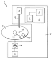
図1は、本発明の分析システム1を示す。本システムは、分析機器2及び制御可能な(使い捨ての)検査エレメント3を含む。
FIG. 1 shows an analysis system 1 of the present invention. The system includes an
分析機器2は、検査エレメント3を回転軸の周囲に動かすための駆動部4を有する。検査エレメント3の中のサンプル液及び他の液体の輸送は、検査エレメント3の回転運動によって外部から制御される。駆動部の回転方向及び回転速度は、駆動部4を駆動制御部5によって制御することで調節される。このようにして、検査エレメント3の特定のセクションにおける液体の流速、流れ方向、及び滞留時間も決定することができる。
The
分析機器2は、検査エレメント3の測定ゾーンにおけるサンプル液の分析結果について特有の測定変量を測定するための光学測定装置7及び分析ユニット8を含む、測定ステーション6を有する。
The
光学測定装置7は、局所的分解検出を用いる蛍光測定用測定装置を含むことが好ましい。二次元分析光学の場合、LED又はレーザーを使用して、検査エレメント3の測定ゾーンを照射し、及び/又は検査ゾーン中の光学的に検出可能な標識を励起する。検出は、CCD光学器又はCMOS光学器を介して行われる。もちろん、先行技術で公知の他の光学測定方法を適用して、特有の測定変量を測定することもできる。
The
投入ステーション9は、検査エレメント3に液体を注ぐための投入針10を有する。投入ステーション9は、本目的のために、注入されるべき液体を保管する一以上の液体貯留槽(図示せず)を含むことができる。サンプル液、又は洗浄溶液若しくは洗浄バッファのような他の液体は、検査エレメント3の供給口11の中に、投入ステーション9を用いて投入される。図1の検査エレメント3では、供給口11は、検査エレメント3におけるサンプル分析チャンネル(図示せず)のサンプル供給口12となる。
The charging station 9 has a charging
単純かつ小型の分析システム1の場合、測定されるべき液体サンプルは、ユーザーによって手動でピペットを用いて、好ましくは回転軸に近接したサンプル供給口12の中に導入される。体液サンプルをサンプル供給口に投入するため、検査エレメント3は、分析機器2のサンプル分注位置に位置付けられる。この場合、投入ステーション9は、供給口11において洗浄溶液を供給するためのみに使用される。
In the case of a simple and small analysis system 1, the liquid sample to be measured is introduced into the
投入ステーション9を用いて、できるかぎり最も正確な容量を投入するため、フラッシング液を用いて準備段階で投入ステーション9及び投入針10を洗い流しておく必要がある。投入針10を通って流れたフラッシング液は、検査エレメント3のフラッシング液供給口13中に入れられる。検査エレメント3は、フラッシング液供給口13が投入針10の下に位置する投入位置に位置付けられる。この事前プライミングは、投入ステーション9又は投入針10に存在する可能性がある気泡によって、投入されるべき液体が十分に投入されないことを防止する。
In order to input the most accurate volume possible using the charging station 9, it is necessary to wash the charging station 9 and the charging
フラッシング又はプライミング液は、フラッシング液供給口13を介して、図3及び4で示すような、隣接するフラッシング液チャンネル32、及びフラッシング液が廃棄されるフラッシング液回収チャンバー31中に流れる。
The flushing or priming liquid flows through the flushing
この事前のフラッシング手順後、検査エレメント3は、投入針10を介して流れ込むサンプル液がサンプル供給口12内に分注されるように、サンプル分注位置に回転される。サンプル液は、サンプル分析チャンネル16のサンプル供給口12を通って、分析結果の測定変量特性の測定が行われる測定ゾーンへと流れる。
After this pre-flushing procedure, the
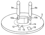
図2は、検査エレメント3、及び2つの投入ステーション9a、9bを有する分析機器2を有する分析システム1の他の実施形態の詳細を示す。投入ステーション9a、9bは、それぞれ投入針10a、10bを有している。
FIG. 2 shows details of another embodiment of an analysis system 1 having a
検査エレメント3は、サンプル供給口12、フラッシング液を受け取るためのフラッシング液供給口13、及び分離した洗浄溶液供給口14を有する。全ての口が(回転軸に近位で)検査エレメント3のある1つの軌道上に位置付けられるように、少なくともフラッシング液供給口13及び洗浄溶液供給口14の検査エレメント3の回転軸からの距離は等しく、好ましくは3つの口(図示するような)の検査エレメント3の回転軸からの距離が等しい。
The
本実施形態において、サンプル液は、投入針10aを用いてサンプル供給口12の中に分注され、洗浄溶液は、投入針10bを用いて洗浄溶液供給口14の中に分注される。気泡が投入針10a、10bから抜けて、針が同時に清浄化されるように、投入針10a、10bの双方を、フラッシング液を用いて最初の投入前に洗い流す。フラッシング液は、いずれの場合もフラッシング後にフラッシング液供給口13へ流れる。好都合にも投入針10a、10bは動く必要がない。全ての供給口が同一軌道上にあるからである。(好ましくは検査エレメント3の中心点又は中心を通って伸びる)回転軸の周囲での検査エレメント3の回転は、それぞれの場合に洗い流される投入針10a、10bの下にフラッシング液供給口13を位置付ける。フラッシング液として洗浄溶液を用いることができ、フラッシングに使用された量の洗浄溶液は、その後(フラッシング液がその他のものであるときと同じ方法で)プライミング構造中に廃棄される。
In the present embodiment, the sample liquid is dispensed into the
図3及び4は、いずれも検査エレメント3の2つの実施形態に関する概略図を示している。2つの検査エレメント3はいずれも、分析機器2中に保持するための基材及び中心孔(駆動孔として用いられる)を有するハウジング15を含む。基材に加えて、円盤型の検査エレメントは、通常、カバー層(明瞭にするため図示されていない)も含む。カバー層も、基本的に流体構造を有していることができるが、通常は液体を供給するための開口又はバルブ口のみを有する。もちろん、中心孔に代えてシャフトを提供することもでき、その回りを検査エレメントが回転する。回転軸は、検査エレメント内部又は外部に位置づけることができる。
FIGS. 3 and 4 both show schematic diagrams for two embodiments of the
検査エレメント3のハウジング15は、流体若しくは微小流体構造、又はクロマトグラフ構造を有する。サンプル液、特に全血は、サンプル供給口12を介して検査エレメント3に供給される。サンプル分析チャンネル16は、流れ方向において、その始端部にサンプル供給口12を、またその終端部に測定ゾーン19を含む。液体サンプルが所定の流れ方向で測定ゾーン19に流れるチャンネルセクション17は、サンプル供給口12と測定ゾーン19との間に伸びている。検査エレメント3における液体輸送は、毛管力及び/又は遠心力によって起こる。
The
図4においてサンプル分析チャンネル16のサンプル供給口12は、流れ方向で開口12の背後に位置する貯留槽36に開口している。液体サンプルは、チャンネルセクション17に流れる前に貯留槽36の中に流れる。液体サンプルの流れ及び/又は流速は、サンプル分析チャンネル16の流体構造を適当に選択することよって操作できる。例えば、チャンネルセクション17,18、21の大きさを、毛管力の発生を促進するように選択することができる。さらに、チャンネルセクションの表面を親水性化することができる。サンプル分析チャンネル16における個々のチャンネルセクションのさらなる流れ又は充填を、外力、好ましくは遠心力の作用の後にのみ可能にすることもできる。
In FIG. 4, the
サンプル分析チャンネル16の異なるセクションは、異なった寸法にする、及び/又は異なる機能を提供することができる。例えば、第1チャンネルセクション18は、体液サンプルと反応する試薬系を含むことができる。この試薬系の少なくとも1つの試薬は、好ましくは乾燥又は凍結乾燥形態で提供される。検査エレメント3に投入する又はピペッティングすることによって供給される少なくとも1つの試薬を液体形態で提供することも可能である。検査エレメントは、この目的のために試薬供給口を有することができる。例えば、液体試薬は、プライミングを(前もって)行った同一の投入システムを用いて適用することができる。
Different sections of the
チャンネルセクション17は、第1チャンネルセクション18、毛管停止部20、及び第2チャンネルセクション21を含む。毛管停止部20は、幾何学的バルブ又は疎水性のバリアとして実施することができる。毛管停止部20に隣接する第2チャンネルセクション21は、毛管停止部20によって計り取られたサンプル量を誘導する。毛管停止部20を通って流れる量は、検査エレメント3の回転速度を利用した遠心力によって制御される。
The
適当な回転速度で、赤血球細胞又は他の細胞サンプル成分の分離が第2チャンネルセクション21で開始される。チャンネルセクション17に含まれ、好ましくは乾燥形態で提供される試薬は、サンプル液が第2チャンネルセクション21へ流入する時には、既に溶解されている。サンプル−試薬の混合物の成分は、チャンバーとして寄与する回収ゾーン22(血漿回収ゾーン)及び23(赤血球回収ゾーン)で捕捉される。
Separation of red blood cells or other cell sample components is initiated in the
回収ゾーン22に隣接する測定ゾーン19は、好ましくは多孔質吸収マトリックスを含む測定チャンバー24を含む。排水チャンバー25は、流れ方向において測定チャンバー24の後に位置する。反応関与物、サンプル成分、及び/又は試薬成分は、測定チャンバー24を通り抜けた後に排水チャンバー25の中に廃棄される。
The
検査エレメント3は、フラッシング液供給口13、フラッシング液回収チャンバー31、及びそれらの間に位置するフラッシング液チャンネル32を含むプライミング構造30を有する。前記チャンバーを通気するためのバルブ33(通気チャンネル34及び通気口35を含む)が、フラッシング液回収チャンバー31の終端部に備えられている。
The
図3の例示的実施形態は、プライミング構造30が検査エレメント3の他の全てのチャンネル構造から分離されていることを明確に示している。また、フラッシング液回収チャンバー31と排水チャンバー25は、互いに分離されており、流体連通していない(流体連結がない)。排水チャンバー25は、測定ゾーン19を通って流れて来た液体を受取るように測定ゾーン19と流体連通していることが好ましい。
The exemplary embodiment of FIG. 3 clearly shows that the priming
さらに、洗浄溶液供給口14が、図3及び図4の検査エレメントの両実施形態で示されている。洗浄溶液チャンネル26は、洗浄溶液供給口14と結合している。洗浄溶液チャンネル26は、好ましくは洗浄溶液供給口14をその開始部に含み、洗浄溶液が洗浄溶液チャンネル26を通して測定チャンバー24に吸引されるように、その終端部で測定ゾーン19と流体連通していることが好ましい。測定チャンバー24のマトリックスが洗浄され、あらゆる過剰な干渉反応関与物が除かれる。その後、洗浄溶液も、排水チャンバー25に到達する。
Furthermore, a cleaning
図4の実施形態において、検査エレメント3は二重機能チャンバー27を有している。二重機能チャンバー27は、好ましくはフラッシング液チャンネル32及び測定ゾーン19と流体連通しており、フラッシング液回収チャンバー31にも、また排水チャンバー25にもなるようになっている。フラッシング液供給口13へ流入するフラッシング液は、フラッシング液チャンネル32を通って、その後、フラッシング液回収チャンバー31として使用される二重機能チャンバー27に導かれる。サンプル液及び/若しくはサンプル液−試薬混合物又は洗浄液もまた、それぞれ測定ゾーン19を通って流れ、その後、排水チャンバー25の機能を担う二重機能チャンバー27中に廃棄される。
In the embodiment of FIG. 4, the
二重機能チャンバー27は、第1流入口28及び第2流入口29を有している。液体は、フラッシング液チャンネル32から第1流入口28を通って二重機能チャンバー27へと流れ出す。測定ゾーン19から流れ出る液体は、第2流入口29を通って二重機能チャンバー27に流れる。
The
もちろん、二重機能チャンバー27は、液体が流入する一の流入口のみを有することもできる。液体は、その流入口を通って、フラッシング液チャンネル32及び測定ゾーン19の両方から流れ込む。この場合、フラッシング液チャンネル32と共有する少なくとも1つのセクションを有する廃棄チャンネルは、測定ゾーン19に連結し、二重機能チャンバー27に開口している。
Of course, the
2 分析機器
3 検査エレメント
6 測定ステーション
9 投入ステーション
12 サンプル供給口
13 フラッシング液供給口
14 洗浄溶液供給口
15 ハウジング
16 サンプル分析チャンネル
19 測定ゾーン
25 排水チャンバー
26 洗浄溶液チャンネル
27 二重機能チャンバー
28 第1流入口
29 第2流入口
31 フラッシング液回収チャンバー
32 フラッシング液チャンネル
2
Claims (17)
前記検査エレメント(3)は、ハウジング(15)、及び該ハウジング(15)により包囲されたサンプル分析チャンネル(16)を有しており、該サンプル分析チャンネル(16)はサンプル供給口(12)及び測定ゾーン(19)を含んでおり、
前記分析機器(2)は、該分析機器(2)上に位置する、検査エレメント(3)内に液体を投入するための投入ステーション(9)を有しており、かつ測定位置に位置付けられた検査エレメント(3)の測定ゾーン(19)における分析結果に関して特徴的な測定変量を測定するための測定ステーション(6)を有しており、
前記検査エレメント(3)は、サンプル供給口(12)を介して供給された体液サンプルをサンプル分析チャンネル(16)内に存在する試薬系と反応させることにより、体液サンプルと試薬系との反応が測定ゾーン(19)における分析結果に関して特徴的な測定変量の変化をもたらすように構成されており、
前記検査エレメント(3)は、サンプル供給口(12)から分離されているフラッシング液供給口(13)、及びフラッシング液回収チャンバー(31)を含んでおり、
前記フラッシング液供給口(13)と前記フラッシング液回収チャンバー(31)はフラッシング液チャンネル(32)を介して互いに流体連通しており、前記フラッシング液チャンネル(32)と前記サンプル分析チャンネル(16)は該フラッシング液チャンネル(32)を通って流れる液体が前記測定ゾーン(19)に到達しないように分離されていることを特徴とする、前記分析システム。 An analysis system for analyzing an analyte contained in a body fluid sample, comprising a test element (3) and an analytical instrument (2),
The test element (3) has a housing (15) and a sample analysis channel (16) surrounded by the housing (15), the sample analysis channel (16) comprising a sample supply port (12) and Including a measurement zone (19),
The analytical instrument (2) has an input station (9) for injecting liquid into the test element (3) located on the analytical instrument (2) and is positioned at the measurement position A measuring station (6) for measuring characteristic measuring variables with respect to the analysis results in the measuring zone (19) of the test element (3);
The test element (3) reacts the bodily fluid sample supplied via the sample supply port (12) with the reagent system existing in the sample analysis channel (16), thereby allowing the reaction between the bodily fluid sample and the reagent system. Configured to bring about a change in the characteristic measurement variable with respect to the analysis results in the measurement zone (19),
The inspection element (3) includes a flushing liquid supply port (13) separated from a sample supply port (12), and a flushing liquid recovery chamber (31),
The flushing liquid supply port (13) and the flushing liquid recovery chamber (31) are in fluid communication with each other via a flushing liquid channel (32), and the flushing liquid channel (32) and the sample analysis channel (16) are connected to each other. The analysis system characterized in that the liquid flowing through the flushing liquid channel (32) is separated so as not to reach the measurement zone (19).
ハウジング(15)及び該ハウジング(15)により包囲されたサンプル分析チャンネル(16)を有し、該サンプル分析チャンネル(16)はサンプル供給口(12)及び測定ゾーン(19)を含んでおり、
該検査エレメント(3)は、サンプル供給口(12)に供給された体液サンプルをサンプル分析チャンネル(16)内に存在する試薬系と反応させることにより、体液サンプルと試薬系との反応が測定ゾーン(19)における分析結果に関して特徴的な測定変量の変化をもたらし、
サンプル供給口(12)から分離されているフラッシング液供給口(13)、及びフラッシング液回収チャンバー(31)が検査エレメント(3)のハウジング(15)内に配置されており、
フラッシング液供給口(13)及びフラッシング液回収チャンバー(31)がフラッシング液チャンネル(32)を介して互いに流体連通しており、
フラッシング液チャンネル(32)及びサンプル分析チャンネル(16)が、フラッシング液チャンネル(32)を通って流れる液体が測定ゾーン(19)に到達しないように分離されている
ことを特徴とする前記検査エレメント。 A test element, in particular a test element for an analysis system for analyzing an analyte contained in a body fluid sample according to any one of claims 1-13,
A housing (15) and a sample analysis channel (16) surrounded by the housing (15), the sample analysis channel (16) including a sample supply port (12) and a measurement zone (19);
The test element (3) reacts the bodily fluid sample supplied to the sample supply port (12) with the reagent system existing in the sample analysis channel (16), so that the reaction between the bodily fluid sample and the reagent system is measured in the measurement zone. Introducing a characteristic measurement variable change with respect to the analysis result in (19),
A flushing liquid supply port (13) separated from the sample supply port (12) and a flushing liquid recovery chamber (31) are arranged in the housing (15) of the test element (3),
The flushing liquid supply port (13) and the flushing liquid recovery chamber (31) are in fluid communication with each other via the flushing liquid channel (32);
Said test element characterized in that the flushing liquid channel (32) and the sample analysis channel (16) are separated so that the liquid flowing through the flushing liquid channel (32) does not reach the measurement zone (19).
前記分析機器(2)が、該分析機器(2)上に位置する、検査エレメント(3)内に液体を投入するための投入ステーション(9)を有し、
前記検査エレメント(3)の各々が、サンプル供給口(12)及び測定ゾーン(19)を含むサンプル分析チャンネル(16)を有し、
前記検査エレメント(3)が、サンプル供給口(12)から分離されたフラッシング液供給口(13)、及びフラッシング液回収チャンバー(31)を含み、
前記フラッシング液供給口(13)が、フラッシング液チャンネル(32)を介してフラッシング液回収チャンバー(31)と流体連通している
分析システム(1)、特に、請求項1に記載の分析システムを用いて、検査エレメント内に液体を供給するための方法であって、
フラッシング液を用いて投入ステーション(9)をフラッシングするステップを含んでおり、
該フラッシング液が、検査エレメントのフラッシング液供給口(13)中に流入し、フラッシング液回収チャンバー(31)に回収される、前記方法。 Including analytical instrument (2) and test element (3),
The analytical instrument (2) has an input station (9) for injecting liquid into the test element (3) located on the analytical instrument (2);
Each of the test elements (3) has a sample analysis channel (16) including a sample supply port (12) and a measurement zone (19);
The test element (3) includes a flushing liquid supply port (13) separated from the sample supply port (12), and a flushing liquid recovery chamber (31),
An analysis system (1) in which the flushing liquid supply port (13) is in fluid communication with a flushing liquid recovery chamber (31) via a flushing liquid channel (32), in particular using an analysis system according to claim 1. A method for supplying liquid into the test element,
Flushing the dosing station (9) with a flushing liquid,
The method, wherein the flushing liquid flows into the flushing liquid supply port (13) of the test element and is collected in the flushing liquid collection chamber (31).
Applications Claiming Priority (1)
| Application Number | Priority Date | Filing Date | Title |
|---|---|---|---|
| EP07022814A EP2062643B1 (en) | 2007-11-24 | 2007-11-24 | Analysis system and method for analysing a bodily fluid sample on an analyte contained therein |
Publications (2)
| Publication Number | Publication Date |
|---|---|
| JP2009128367A true JP2009128367A (en) | 2009-06-11 |
| JP2009128367A5 JP2009128367A5 (en) | 2011-11-17 |
Family
ID=39284231
Family Applications (1)
| Application Number | Title | Priority Date | Filing Date |
|---|---|---|---|
| JP2008298682A Withdrawn JP2009128367A (en) | 2007-11-24 | 2008-11-21 | Analytical system and method for analyzing analyte contained in body fluid |
Country Status (6)
| Country | Link |
|---|---|
| US (1) | US8114351B2 (en) |
| EP (1) | EP2062643B1 (en) |
| JP (1) | JP2009128367A (en) |
| CN (1) | CN101446593A (en) |
| AT (1) | ATE541639T1 (en) |
| CA (1) | CA2643663C (en) |
Cited By (8)
| Publication number | Priority date | Publication date | Assignee | Title |
|---|---|---|---|---|
| JP2013518276A (en) * | 2010-01-29 | 2013-05-20 | サムスン エレクトロニクス カンパニー リミテッド | Centrifugal force-based microfluidic device and method for detecting an analyte in a fluid sample using the same |
| JP2014070991A (en) * | 2012-09-28 | 2014-04-21 | Toppan Printing Co Ltd | Biochemical reaction chip for analyzing plural samples, and analysis device thereof |
| JP5932077B1 (en) * | 2015-02-24 | 2016-06-08 | シャープ株式会社 | Component analysis container |
| WO2016121266A1 (en) * | 2015-01-30 | 2016-08-04 | シャープ株式会社 | Sample analysis device and sample analysis method |
| JP2017096972A (en) * | 2013-04-15 | 2017-06-01 | ベクトン・ディキンソン・アンド・カンパニーBecton, Dickinson And Company | Biological fluid separation device |
| JP2017516086A (en) * | 2014-05-13 | 2017-06-15 | エフ.ホフマン−ラ ロシュ アーゲーF. Hoffmann−La Roche Aktiengesellschaft | A rotatable cartridge for measuring properties of biological samples |
| JP2017116544A (en) * | 2015-12-21 | 2017-06-29 | エフ ホフマン−ラ ロッシュ アクチェン ゲゼルシャフト | Blood collector with capillary structure |
| US10028690B2 (en) | 2013-04-15 | 2018-07-24 | Becton, Dickinson And Company | Biological fluid collection device and biological fluid separation and testing system |
Families Citing this family (15)
| Publication number | Priority date | Publication date | Assignee | Title |
|---|---|---|---|---|
| US20050249641A1 (en) * | 2004-04-08 | 2005-11-10 | Boehringer Ingelheim Microparts Gmbh | Microstructured platform and method for manipulating a liquid |
| EP2163901A1 (en) * | 2008-09-10 | 2010-03-17 | Roche Diagnostics GmbH | Method and metering device for metering a fluid into a receptacle channel of a testing element for bodily fluid analysis |
| GB2472236A (en) * | 2009-07-29 | 2011-02-02 | Iti Scotland Ltd | Apparatus for analysing microfluidic devices |
| CN102430549B (en) * | 2011-12-15 | 2013-10-23 | 深圳市尚荣医疗股份有限公司 | Cleaning device for full-automatic biochemical analyzer and cleaning method thereof |
| CN105745546B (en) | 2013-03-15 | 2017-10-13 | 雅培制药有限公司 | With below can injection system automated diagnostic analyzer and correlation technique |
| US10001497B2 (en) | 2013-03-15 | 2018-06-19 | Abbott Laboratories | Diagnostic analyzers with pretreatment carousels and related methods |
| CN116794337A (en) | 2013-03-15 | 2023-09-22 | 雅培制药有限公司 | Automated diagnostic analyzer with vertically disposed carousel and related methods |
| KR101859860B1 (en) | 2014-06-06 | 2018-05-18 | 에프. 호프만-라 로슈 아게 | Rotatable cartridge with a metering chamber for analyzing a biological sample |
| EP2952258A1 (en) | 2014-06-06 | 2015-12-09 | Roche Diagnostics GmbH | Rotatable cartridge for analyzing a biological sample |
| EP2952257A1 (en) | 2014-06-06 | 2015-12-09 | Roche Diagnostics GmbH | Rotatable cartridge for processing and analyzing a biological sample |
| EP2957890A1 (en) | 2014-06-16 | 2015-12-23 | Roche Diagnostics GmbH | Cartridge with a rotatable lid |
| EP3173149A1 (en) | 2015-11-26 | 2017-05-31 | Roche Diagnostics GmbH | Determining a quantity of an analyte in a blood sample |
| EP3231513B1 (en) | 2016-04-14 | 2022-03-02 | Roche Diagnostics GmbH | Cartridge and optical measurement of an analyte with said cartridge |
| US10639635B2 (en) * | 2016-10-07 | 2020-05-05 | Biosurfit, SA | Device and method for handling liquid |
| EP3324189B1 (en) | 2016-11-16 | 2021-01-06 | Roche Diagnostics GmbH | Rotatable cartridge with multiple metering chambers |
Family Cites Families (11)
| Publication number | Priority date | Publication date | Assignee | Title |
|---|---|---|---|---|
| DE3044372A1 (en) | 1980-11-25 | 1982-07-08 | Boehringer Mannheim Gmbh, 6800 Mannheim | ROTOR UNIT WITH INSERT ELEMENTS FOR A CENTRIFUGAL ANALYZER |
| US4580896A (en) | 1983-11-07 | 1986-04-08 | Allied Corporation | Multicuvette centrifugal analyzer rotor with annular recessed optical window channel |
| US4713974A (en) | 1986-04-18 | 1987-12-22 | Varian Associates, Inc./Scientific Systems, Inc. | Autosampler |
| US5746982A (en) * | 1996-02-29 | 1998-05-05 | Advanced Chemtech, Inc. | Apparatus for automated synthesis of chemical compounds |
| SI20346A (en) | 1997-02-28 | 2001-02-28 | Burstein Laboratories, Inc. | Laboratory in a disk |
| US7261859B2 (en) * | 1998-12-30 | 2007-08-28 | Gyros Ab | Microanalysis device |
| US6720187B2 (en) * | 2000-06-28 | 2004-04-13 | 3M Innovative Properties Company | Multi-format sample processing devices |
| US20040265171A1 (en) | 2003-06-27 | 2004-12-30 | Pugia Michael J. | Method for uniform application of fluid into a reactive reagent area |
| US20040265172A1 (en) * | 2003-06-27 | 2004-12-30 | Pugia Michael J. | Method and apparatus for entry and storage of specimens into a microfluidic device |
| US7527763B2 (en) * | 2005-07-05 | 2009-05-05 | 3M Innovative Properties Company | Valve control system for a rotating multiplex fluorescence detection device |
| WO2007106013A1 (en) * | 2006-03-13 | 2007-09-20 | Gyros Patent Ab | Enhanced magnetic particle steering |
-
2007
- 2007-11-24 EP EP07022814A patent/EP2062643B1/en active Active
- 2007-11-24 AT AT07022814T patent/ATE541639T1/en active
-
2008
- 2008-11-12 CA CA2643663A patent/CA2643663C/en not_active Expired - Fee Related
- 2008-11-21 JP JP2008298682A patent/JP2009128367A/en not_active Withdrawn
- 2008-11-21 US US12/275,707 patent/US8114351B2/en active Active
- 2008-11-24 CN CN200810181598.3A patent/CN101446593A/en active Pending
Cited By (15)
| Publication number | Priority date | Publication date | Assignee | Title |
|---|---|---|---|---|
| US9164091B2 (en) | 2010-01-29 | 2015-10-20 | Samsung Electronics Co., Ltd. | Centrifugal micro-fluidic device and method for detecting analytes from liquid specimen |
| JP2013518276A (en) * | 2010-01-29 | 2013-05-20 | サムスン エレクトロニクス カンパニー リミテッド | Centrifugal force-based microfluidic device and method for detecting an analyte in a fluid sample using the same |
| JP2014070991A (en) * | 2012-09-28 | 2014-04-21 | Toppan Printing Co Ltd | Biochemical reaction chip for analyzing plural samples, and analysis device thereof |
| US10136849B2 (en) | 2013-04-15 | 2018-11-27 | Becton, Dickinson And Company | Biological fluid collection device and biological fluid separation and testing system |
| US11974846B2 (en) | 2013-04-15 | 2024-05-07 | Becton, Dickinson And Company | Biological fluid transfer device and biological fluid sampling system |
| JP2017096972A (en) * | 2013-04-15 | 2017-06-01 | ベクトン・ディキンソン・アンド・カンパニーBecton, Dickinson And Company | Biological fluid separation device |
| US10827965B2 (en) | 2013-04-15 | 2020-11-10 | Becton, Dickinson And Company | Biological fluid collection device and biological fluid separation and testing system |
| US10028690B2 (en) | 2013-04-15 | 2018-07-24 | Becton, Dickinson And Company | Biological fluid collection device and biological fluid separation and testing system |
| JP2017516086A (en) * | 2014-05-13 | 2017-06-15 | エフ.ホフマン−ラ ロシュ アーゲーF. Hoffmann−La Roche Aktiengesellschaft | A rotatable cartridge for measuring properties of biological samples |
| WO2016121266A1 (en) * | 2015-01-30 | 2016-08-04 | シャープ株式会社 | Sample analysis device and sample analysis method |
| JP2016142558A (en) * | 2015-01-30 | 2016-08-08 | シャープ株式会社 | Sample analysis device and sample analysis method |
| JP2016156701A (en) * | 2015-02-24 | 2016-09-01 | シャープ株式会社 | Container for component analysis |
| JP5932077B1 (en) * | 2015-02-24 | 2016-06-08 | シャープ株式会社 | Component analysis container |
| JP2017116544A (en) * | 2015-12-21 | 2017-06-29 | エフ ホフマン−ラ ロッシュ アクチェン ゲゼルシャフト | Blood collector with capillary structure |
| JP7007799B2 (en) | 2015-12-21 | 2022-02-10 | エフ ホフマン-ラ ロッシュ アクチェン ゲゼルシャフト | Blood sampling device with capillary structure |
Also Published As
| Publication number | Publication date |
|---|---|
| CA2643663A1 (en) | 2009-05-24 |
| CN101446593A (en) | 2009-06-03 |
| US20090137062A1 (en) | 2009-05-28 |
| EP2062643B1 (en) | 2012-01-18 |
| CA2643663C (en) | 2011-09-20 |
| ATE541639T1 (en) | 2012-02-15 |
| US8114351B2 (en) | 2012-02-14 |
| EP2062643A1 (en) | 2009-05-27 |
Similar Documents
| Publication | Publication Date | Title |
|---|---|---|
| JP2009128367A (en) | Analytical system and method for analyzing analyte contained in body fluid | |
| JP6838127B2 (en) | Test cartridge with integrated transfer module | |
| KR101930610B1 (en) | Rotatable cartridge for analyzing a biological sample | |
| JP4361879B2 (en) | Chemical analysis apparatus and chemical analysis cartridge | |
| US8642293B2 (en) | Disposable device for analyzing a liquid sample containing a nucleic acid with a nucleic acid amplification apparatus | |
| KR101869184B1 (en) | Rotatable cartridge for measuring a property of a biological sample | |
| KR101923278B1 (en) | Blood collector with capillary structure | |
| KR101859860B1 (en) | Rotatable cartridge with a metering chamber for analyzing a biological sample | |
| KR101930611B1 (en) | Rotatable cartridge for processing and analyzing a biological sample | |
| JP6790081B2 (en) | Determining the amount of sample in a blood sample | |
| US11701664B2 (en) | Analysis device and method | |
| US9039995B2 (en) | Self-metering system and testing device with casing and sliding member to cut-off and set sample volume |
Legal Events
| Date | Code | Title | Description |
|---|---|---|---|
| A521 | Written amendment |
Free format text: JAPANESE INTERMEDIATE CODE: A523 Effective date: 20110928 |
|
| A621 | Written request for application examination |
Free format text: JAPANESE INTERMEDIATE CODE: A621 Effective date: 20110928 |
|
| A761 | Written withdrawal of application |
Free format text: JAPANESE INTERMEDIATE CODE: A761 Effective date: 20111027 |