JP2009106574A - Apparatus and program for respiratory sound analysis - Google Patents
Apparatus and program for respiratory sound analysis Download PDFInfo
- Publication number
- JP2009106574A JP2009106574A JP2007282734A JP2007282734A JP2009106574A JP 2009106574 A JP2009106574 A JP 2009106574A JP 2007282734 A JP2007282734 A JP 2007282734A JP 2007282734 A JP2007282734 A JP 2007282734A JP 2009106574 A JP2009106574 A JP 2009106574A
- Authority
- JP
- Japan
- Prior art keywords
- sound
- respiratory sound
- instantaneous
- respiratory
- peak
- Prior art date
- Legal status (The legal status is an assumption and is not a legal conclusion. Google has not performed a legal analysis and makes no representation as to the accuracy of the status listed.)
- Pending
Links
Images


Landscapes
- Measurement Of The Respiration, Hearing Ability, Form, And Blood Characteristics Of Living Organisms (AREA)
Abstract
Description
本発明は、呼吸音解析装置及びプログラムに関する。 The present invention relates to a respiratory sound analysis device and a program.
呼吸音を聴取し、診断することは聴診として古くから用いられてきた診断方法である。呼吸音の中の異常音は副雑音と呼ばれ、様々な種類の音が知られている。副雑音の中でもラ音は重要で、その自動的な検出はこれまでにも試みられている(例えば、特許文献1参照)。
呼吸信号にはさまざまな、ノイズ信号が含まれる。例えば、音声や咳、心音、マイクを擦る摩擦音など非常に多岐に渡る。このノイズをいかに誤検出せず、かつ目的とするラ音を精度よく検出するかが、大きな課題であった。 The respiration signal includes various noise signals. For example, there are a wide variety of voices, coughs, heart sounds, and friction sounds that rub the microphone. How to detect this noise erroneously and accurately detect the target sound is a big problem.
ラ音の中でも断続性ラ音(クラックル)の検出は難しく、特にコースクラックル(水泡音)の検出精度が低い問題があった。 Among the rales, it is difficult to detect intermittent rales (cracks), and in particular, there is a problem that the detection accuracy of coarse crackles (water bubbles) is low.
本発明は、以上のような問題に鑑みてなされたものであり、ラ音の検出を精度良く行うことができる呼吸音解析装置を提供することを目的としている。 The present invention has been made in view of the above-described problems, and an object of the present invention is to provide a respiratory sound analysis apparatus that can accurately detect rales.
本発明の呼吸音解析装置は、被検者の呼吸音を測定し呼吸音データを出力する呼吸音測定部と、前記呼吸音測定部により測定された呼吸音データに基づいて呼吸音の解析を行う呼吸音解析部と、を有し、前記呼吸音解析部は、前記呼吸音データをヒルベルト変換して解析信号を算出し、解析信号から包絡線、瞬時周波数及び瞬時帯域幅を算出し、包絡線からラ音の候補となるピークを抽出し、抽出したピークに対応して瞬時周波数又は瞬時帯域幅のうち少なくとも1つを算出し、算出した瞬時周波数又は瞬時帯域幅のうち少なくとも1つに基づいてラ音を検出することを特徴としている。 The respiratory sound analyzer of the present invention measures a respiratory sound of a subject and outputs respiratory sound data, and analyzes the respiratory sound based on the respiratory sound data measured by the respiratory sound measuring unit. A breathing sound analyzing unit that performs Hilbert transform on the breathing sound data to calculate an analysis signal, calculates an envelope, an instantaneous frequency, and an instantaneous bandwidth from the analysis signal, A peak that is a candidate for a ra sound is extracted from a line, at least one of an instantaneous frequency or an instantaneous bandwidth is calculated corresponding to the extracted peak, and based on at least one of the calculated instantaneous frequency or instantaneous bandwidth It is characterized by detecting the noise.
本発明のプログラムは、入力された呼吸音データをヒルベルト変換して解析信号を算出するステップと、解析信号から包絡線、瞬時周波数及び瞬時帯域幅を算出するステップと、包絡線からラ音の候補となるピークを抽出するステップと、抽出したピークに対応して瞬時周波数又は瞬時帯域幅のうち少なくとも1つを算出するステップと、算出した瞬時周波数又は瞬時帯域幅のうち少なくとも1つに基づいてラ音を検出するステップと、をコンピュータに実行させることを特徴としている。 The program of the present invention includes a step of calculating an analysis signal by performing Hilbert transform on input respiratory sound data, a step of calculating an envelope, an instantaneous frequency and an instantaneous bandwidth from the analysis signal, and a candidate for a ra sound from the envelope Extracting at least one of an instantaneous frequency or an instantaneous bandwidth corresponding to the extracted peak, and a step based on at least one of the calculated instantaneous frequency or instantaneous bandwidth. And a step of detecting a sound by a computer.
本発明によれば、瞬時周波数、瞬時帯域幅を用いることにより、ラ音の検出を精度良く行うことができる。 According to the present invention, by using the instantaneous frequency and the instantaneous bandwidth, it is possible to accurately detect the rale.
以下、図面に基づいて本発明の実施形態について説明するが、一例であり、本実施形態に限定するものではない。 Hereinafter, although an embodiment of the present invention is described based on a drawing, it is an example and is not limited to this embodiment.
(第1の実施形態)
[装置構成]
図1は、本実施形態に係る呼吸音解析装置の構成図である。呼吸音解析装置1は、呼吸音測定部10及び呼吸音解析部30から構成され、通信媒体Lを介して互いに接続されている。この通信媒体Lは、有線であっても無線であってもよい。無線により接続すれば、呼吸音測定部10に用いられているセンサに不要な振動を与える機会を減らすことができるとともに、被検者の行動の制約を少なくすることができる。
(First embodiment)
[Device configuration]
FIG. 1 is a configuration diagram of a respiratory sound analysis apparatus according to the present embodiment. The respiratory
呼吸音測定部10は、入力される呼吸音を呼吸音信号に変換するコンデンサマイク等の密着型のマイクロフォン11、マイクロフォン11により変換された呼吸音信号を増幅する増幅器12、増幅器12により増幅された呼吸音信号を平滑化処理する平滑回路13、平滑回路13により処理された呼吸音信号を呼吸音データに変換するA/D変換器14、及びA/D変換器14により変換された呼吸音データを呼吸音解析部30に送信するI/F15から構成されている。ここで、A/D変換器14は、例えばサンプリング周波数Fs=11.025kHzで呼吸音信号から呼吸音データを生成する。
The respiratory
呼吸音解析部30は、呼吸音測定部10からの呼吸音データを受信するI/F31、I/F31で受信された呼吸音データをプログラムに従って処理するCPU32、CPU32での処理に必要なプログラムやデータ等を記憶するROM33、CPU32での処理に必要なプログラムやデータ等を一時的に記憶するRAM34、CPU32での処理結果等をハードディスク、DVD−R、CD−R等に保存する外部記憶装置35、各種データを入力する入力部36、及びCPU32での処理結果等を表示する表示部37から構成されている。
The breathing
呼吸音解析部30は、専用の情報処理装置で構成されていてもよいし、汎用のパーソナルコンピュータで構成されていてもよい。パーソナルコンピュータであれば、持ち運びが容易にできる携帯情報端末(PDA)であることが好ましい。
The respiratory
本実施形態においては、呼吸音測定部10にA/D変換器14を設けたが、呼吸音解析部30にA/D変換器を設けてもよい。
In the present embodiment, the A /
[呼吸音測定処理]
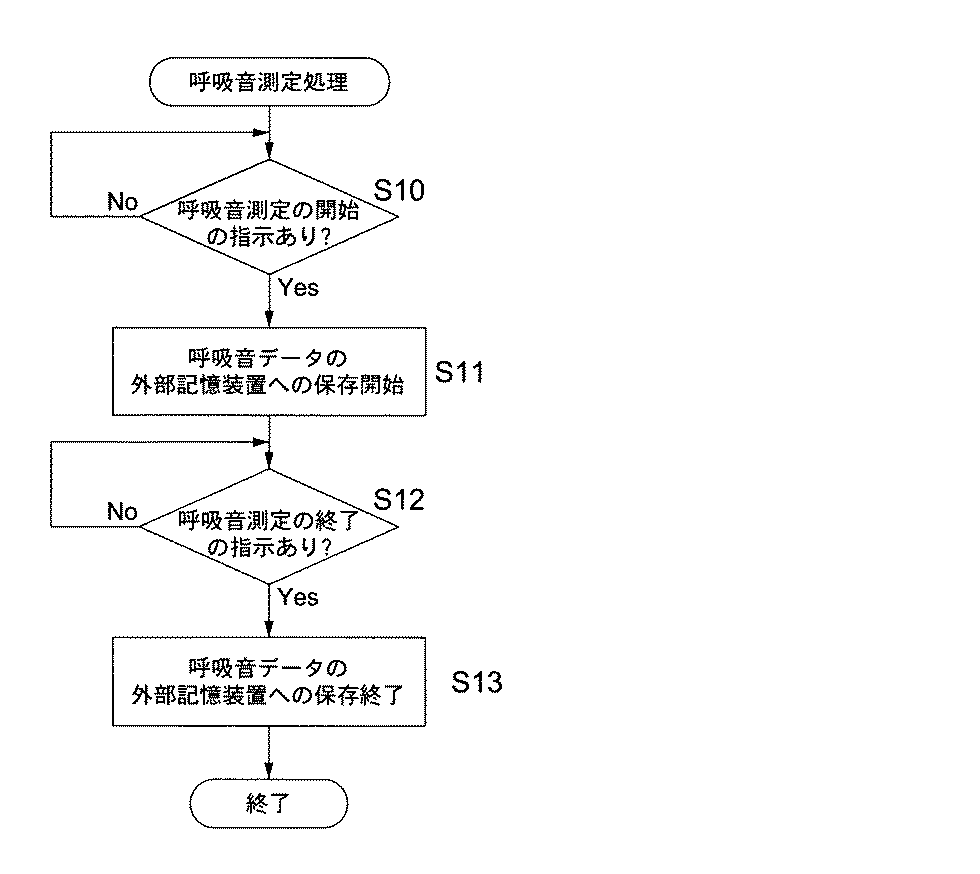
図2は、本実施形態に係る呼吸音測定処理のフロー図である。この呼吸音測定処理フローは、ROM33内の呼吸音測定プログラムに基づいて、CPU32により実行されるフローである。予め入力部36により被検者を特定するID等は入力されているものとする。
[Respiratory sound measurement processing]
FIG. 2 is a flowchart of the respiratory sound measurement process according to the present embodiment. This respiration sound measurement processing flow is a flow executed by the
まず、CPU32は、入力部36から呼吸音測定の開始が指示されたか否かを判断する(ステップS10)。呼吸音測定の開始が指示されたと判断すると(ステップS10;Yes)、CPU32は、呼吸音測定部10からの呼吸音データを外部記憶装置35に保存する動作を開始させる(ステップS41)。このとき、被検者のID及び時刻に対応付けて呼吸音データは保存される。呼吸音測定の開始が指示されていないと判断すると(ステップS10;No)、ステップS10に戻り呼吸音測定の開始が指示されるまで待機する。
First, the
次に、CPU32は、呼吸音測定の終了が指示されたか否かを判断する(ステップS12)。呼吸音測定の終了が指示されたと判断すると(ステップS12;Yes)、CPU32は、呼吸音測定部10からの呼吸音デーを外部記憶装置35に保存する動作を終了させる(ステップS13)。呼吸音測定の終了が指示されていないと判断すると(ステップS12;No)、ステップS12に戻り呼吸音測定の終了が指示されるまで待機する。
Next, the
[解析パラメータ]
まず、本発明の解析に用いるパラメータについて説明する。
[Analysis parameters]
First, parameters used for the analysis of the present invention will be described.
解析信号z(t)は複素数の信号であり、その実部は原信号と等しく、虚部は原信号のヒルベルト変換である。原信号をx(t)とし、x(t)の解析信号をz(t)とすると、 The analytic signal z (t) is a complex signal, whose real part is equal to the original signal, and whose imaginary part is the Hilbert transform of the original signal. If the original signal is x (t) and the analytic signal of x (t) is z (t),
と表される。但し、 It is expressed. However,
であり、A(t)、ψ(t)は、それぞれx(t)の包絡線及び瞬時位相を示す。 A (t) and ψ (t) denote the envelope and instantaneous phase of x (t), respectively.
瞬時周波数f(t)は、 The instantaneous frequency f (t) is
で表される。 It is represented by
瞬時帯域幅b(t)は、 The instantaneous bandwidth b (t) is
で表される。 It is represented by
[ラ音検出の考え方]
ラ音の注目すべき特徴は時間的局在性である。本実施形態では、エネルギー集中指数ECI(Energy Concentration Index)という指標を用いてラ音を検出する。
[La Sound Detection Concept]
A notable feature of ra sound is temporal localization. In the present embodiment, the sound is detected using an index called an energy concentration index ECI (Energy Concentration Index).
エネルギー集中指数ECIは、包絡線の最大値(極大値)の近傍における原波形のエネルギーE1と、包絡線の最大値を中心としてラ音1つ分程度の時間幅における原波形のエネルギーE2との比(E1/E2)で表される。エネルギー集中指数ECIは、波形のエネルギーがどのくらい最大値付近に集中しているかの指標となり、ラ音の指標とできる。 The energy concentration index ECI is the energy E1 of the original waveform in the vicinity of the maximum value (maximum value) of the envelope, and the energy E2 of the original waveform in the time width of about one ra sound centered on the maximum value of the envelope. It is expressed as a ratio (E1 / E2). The energy concentration index ECI is an index of how much the energy of the waveform is concentrated near the maximum value, and can be used as an index of rales.
本アルゴリズムでは、包絡線の最大値付近における瞬時周波数の平均値の逆数をTとして(Tは、そのパルス波形の振動の周期の推定値となる)、E1の値はTの2倍の時間幅に含まれるエネルギー(データの2乗和)、E2の値はTの6倍の時間幅に含まれるエネルギーとした。 In this algorithm, the reciprocal of the average value of the instantaneous frequency in the vicinity of the maximum value of the envelope is T (T is an estimated value of the oscillation period of the pulse waveform), and the value of E1 is twice as long as T. Energy (sum of squares of data), and the value of E2 is energy included in a time width of 6 times T.
瞬時周波数は、ラ音部分ではラ音の(主要)周波数を安定的に示す。信号のない部分では小刻みにばらつく。瞬時帯域幅は、ラ音のピークにおいてほぼゼロになる。ラ音部分で下に凸のお椀型の変化を示す。信号のない部分では大きくばらつく。 The instantaneous frequency stably indicates the (main) frequency of the ra sound in the ra sound portion. It varies in small increments where there is no signal. The instantaneous bandwidth becomes almost zero at the peak of the rale. This shows a bowl-shaped change that protrudes downward in the ra sound. It varies greatly in areas where there is no signal.
本実施形態では、ラ音の候補点において、エネルギー集中指数ECIがある閾値以上(波形の時間的局在性が大きい)、瞬時周波数の変動が少ない、瞬時帯域幅が小さい、及び候補点の近傍における瞬時帯域幅の積分値(データの総和)(以下、BSと称する)がある閾値以上(瞬時帯域幅の変化がお椀型であるか否かの判断)の場合、ラ音であると判定する。 In the present embodiment, the energy concentration index ECI is equal to or greater than a certain threshold (the waveform has a large temporal localization), the fluctuation of the instantaneous frequency is small, the instantaneous bandwidth is small, and the vicinity of the candidate point. If the integrated value of the instantaneous bandwidth (sum of data) (hereinafter referred to as BS) is greater than or equal to a certain threshold value (determining whether the change in instantaneous bandwidth is bowl-shaped) or not, it is determined to be a ra sound. .
[ラ音検出における呼吸音解析処理]
図3は、第1の実施形態に係る呼吸音解析処理のフロー図である。
[Respiratory sound analysis processing in rale detection]
FIG. 3 is a flowchart of the respiratory sound analysis process according to the first embodiment.
本呼吸音解析処理は、取得した呼吸音データを解析し、ラ音の検出を行う処理である。ROM33内の呼吸音解析プログラム(本発明のプログラム)に基づいて、CPU32により実行される。尚、予め入力部36により被検者を特定するID等は入力されているものとする。
This breathing sound analysis process is a process of analyzing the acquired breathing sound data and detecting a rale. It is executed by the
まず、CPU32は、入力部36から呼吸音解析の指示が入力されたか否かを判断する(ステップS20)。呼吸音解析の指示が入力されたと判断すると(ステップS20;Yes)、CPU32は、被検者IDに対応する呼吸音データを外部記憶装置35から読み出し、RAM34にロードする(ステップS21)。呼吸音解析の指示が入力されていないと判断すると(ステップS20;No)、ステップS20に戻り呼吸音解析の指示が入力されるまで待機する。
First, the
次に、CPU32は、RAM34にロードされた呼吸音データ(サンプリング周波数Fs=11.025kHz)を131072点毎に区分する(ステップS22)。
Next, the
次に、CPU32は、各区間で心音等の雑音を除去するために、カットオフ周波数50Hzのハイパスフィルタをかける(ステップS23)。
Next, the
次に、CPU32は、データをフーリエ変換し、直流成分を1倍、正の周波数成分を2倍、負の周波数成分をゼロとして、逆フーリエ変換を行うことにより解析信号z(t)を得る(ステップS24)。フーリエ変換を用いる方法のほかにヒルベルト変換器(ディジタルフィルタ)を用いる方法もある。
Next, the
次に、CPU32は、包絡線A(t)、瞬時周波数f(t)、瞬時帯域幅b(t)を前掲の式により算出する。微分は差分に置き換えた。それぞれの結果を図4に示す。図4(a)は原信号x(t)、図4(b)は包絡線a(t)、図4(c)はエネルギー集中指数ECI、図4(d)は瞬時周波数f(t)、図4(e)は瞬時帯域幅b(t)である。さらにf(t)の時間微分(差分)をとって2乗した量v(t)を算出する(ステップS25)。
Next, the
次に、CPU32は、重みを3角形型、幅を55点としてA(t)の移動平均As(t)を算出する。同様にb(t)及びv(t)についても、幅を35点としてそれぞれの移動平均bs(t)及びvs(t)を算出する(ステップS26)。
Next, the
次に、CPU32は、移動平均As(t)が極大となる位置を探してラ音の位置の候補とする(ステップS27)。
Next, the
次に、CPU32は、それぞれの候補位置において、エネルギー集中指数ECIを算出する。候補位置を中心として、32点のデータ幅におけるf(t)の平均値FAを求める。ECI=E1/E2とし、E1を求める際のデータ数N1=2×Fs/FA、E2を求める際のデータ数N2=6Fs/FAとする。原信号x(t)において、候補位置を中心としてN1点の幅におけるx(t)の2乗和をE1とし、候補位置を中心としてN2点の幅におけるx(t)の2乗和をE2としてエネルギー集中指数ECIを算出する(ステップS28)。
Next, the
次に、CPU32は、候補位置において、瞬時帯域幅の積分値BSを計算する。瞬時帯域幅b(t)において、候補位置を中心として、442点の幅におけるb(t)の総和を求め、BSとする(ステップS29)。
Next, the
ラ音の候補位置において、エネルギー集中指数ECIが0.65以上、vs(t)が3.04×10¹⁰以下、瞬時帯域幅の移動平均bs(t)が154以下、候補点の近傍における瞬時帯域幅の積分値BSが12以上、である場合、その位置の波形をラ音と決定する(ステップS30)。図4においては、図4(a)の原信号x(t)上に3角形の印で示した。 At the candidate position of the sound, the energy concentration index ECI is 0.65 or more, vs (t) is 3.04 × 10 10 or less, the moving average bs (t) of the instantaneous bandwidth is 154 or less, and the instantaneous near the candidate point If the integrated value BS of the bandwidth is 12 or more, the waveform at that position is determined as a ra sound (step S30). In FIG. 4, a triangular mark is shown on the original signal x (t) in FIG.
以上のように、本実施形態によれば、瞬時周波数、瞬時帯域幅を用いることにより、ラ音の検出を精度良く行うことができる。このため、ラ音のない部分(ノイズ部分)を判別することができ、入力信号の振幅変化にロバストなアルゴリズムが実現できる。また、瞬時周波数を用いて、ラ音の(主要)周波数などを容易に求めることが可能である。 As described above, according to the present embodiment, by using the instantaneous frequency and the instantaneous bandwidth, the rale can be detected with high accuracy. For this reason, a portion without noise (noise portion) can be discriminated, and an algorithm robust to changes in the amplitude of the input signal can be realized. In addition, it is possible to easily obtain the (main) frequency of the ra sound using the instantaneous frequency.
本実施形態では、瞬時帯域幅の変化がお椀型であるか否かの判断も組み込まれており、精度を高める上で好ましい。 In the present embodiment, a determination as to whether or not the instantaneous bandwidth change is bowl-shaped is also incorporated, which is preferable for improving accuracy.
(第2の実施形態)
装置構成及び呼吸音測定処理については、第1の実施形態と同様であり、説明を省略する。
(Second Embodiment)
The apparatus configuration and the respiratory sound measurement process are the same as those in the first embodiment, and a description thereof will be omitted.
[ラ音検出の考え方]
第1の実施形態ではエネルギー集中指数ECIを用いてラ音の検出を行ったが、第2の実施形態においては、後述するクレストインデックス又は包絡線のピーク値まわりの2次モーメントを用いてラ音の検出を行う。
[La Sound Detection Concept]
In the first embodiment, the rale is detected using the energy concentration index ECI. However, in the second embodiment, the rae sound is detected using a second moment around the peak value of the crest index or envelope described later. Detection is performed.
クレストインデックスCI(波高指数)は、波高率と同じであり、包絡線の最大値を現波形の実効値で除した値と定義する。波形がパルスに近いほど大きな値を示す。 The crest index CI (wave height index) is the same as the wave height factor, and is defined as a value obtained by dividing the maximum value of the envelope by the effective value of the current waveform. The closer the waveform is to the pulse, the larger the value.
2次モーメントは、確率における分散と同じであり、分布の広がりの程度を示す。ラ音の包絡線では、相対的に低い値を示す。 The second moment is the same as the variance in probability and indicates the extent of the distribution spread. The ra sound envelope shows a relatively low value.
本実施形態では、ラ音の候補点において、クレストインデックスCIがある閾値以上又は2次モーメントの値がある閾値以下(波形の時間的局在性が大きい)、瞬時周波数の変動が少ない、及び瞬時帯域幅が小さい場合、ラ音であると判定する。 In the present embodiment, at the candidate point of the ra sound, the crest index CI is greater than or equal to a certain threshold value or less than a certain threshold value (the temporal localization of the waveform is large), the fluctuation of the instantaneous frequency is small, and the instantaneous When the bandwidth is small, it is determined that the sound is a rale.
[ラ音検出における呼吸音解析処理]
図5は、第2の実施形態に係る呼吸音解析処理のフロー図である。一例としてクレストインデックスCIを用いてラ音の検出する場合について説明するが、2次モーメントを用いる場合も基本的に同様である。
[Respiratory sound analysis processing in rale detection]
FIG. 5 is a flowchart of the breathing sound analysis process according to the second embodiment. As an example, a case where a rale is detected using the crest index CI will be described.
本呼吸音解析処理は、取得した呼吸音データを解析し、ラ音の検出を行う処理である。ROM33内の呼吸音解析プログラムに基づいて、CPU32により実行される。尚、予め入力部36により被検者を特定するID等は入力されているものとする。
The respiratory sound analysis process is a process of analyzing the acquired respiratory sound data and detecting a rale sound. It is executed by the
まず、CPU32は、入力部36から呼吸音解析の指示が入力されたか否かを判断する(ステップS40)。呼吸音解析の指示が入力されたと判断すると(ステップS40;Yes)、CPU32は、被検者IDに対応する呼吸音データを外部記憶装置35から読み出し、RAM34にロードする(ステップS41)。呼吸音解析の指示が入力されていないと判断すると(ステップS40;No)、ステップS40に戻り呼吸音解析の指示が入力されるまで待機する。
First, the
次に、CPU32は、RAM34にロードされた呼吸音データ(サンプリング周波数Fs=11.025kHz)を131072点毎に区分する(ステップS42)。
Next, the
次に、CPU32は、各区間で心音等の雑音を除去するために、カットオフ周波数50Hzのハイパスフィルタをかける(ステップS43)。
Next, the
次に、CPU32は、データをフーリエ変換し、直流成分を1倍、正の周波数成分を2倍、負の周波数成分をゼロとして、逆フーリエ変換を行うことにより解析信号z(t)を得る(ステップS44)。フーリエ変換を用いる方法のほかにヒルベルト変換器(ディジタルフィルタ)を用いる方法もある。
Next, the
次に、CPU32は、包絡線A(t)、瞬時周波数f(t)、瞬時帯域幅b(t)を前掲の式により算出する。微分は差分に置き換えた。さらにf(t)の時間微分(差分)をとって2乗した量v(t)を算出する(ステップS45)。
Next, the
次に、CPU32は、重みを3角形型、幅を55点としてA(t)の移動平均As(t)を算出する。同様にb(t)及びv(t)についても、幅を35点としてそれぞれの移動平均bs(t)及びvs(t)を算出する(ステップS46)。
Next, the
次に、CPU32は、移動平均As(t)が極大となる位置を探してラ音の位置の候補とする。但し、移動平均As(t)の平均値を求めて、その3.2倍以下のピークは候補から除く(ステップS47)。
Next, the
次に、CPU32は、それぞれのピークのクレストインデックスCIを算出する。クレストインデックスCIを算出するデータ長は、波形のピーク位置(ラ音の候補)を中心とする1024点の幅とする(ステップS48)。
Next, the
ラ音の候補位置において、クレストインデックスCIが2.6以上、瞬時帯域幅の移動平均bs(t)が154以下、及びvs(t)が3.04×10¹⁰以下である場合、その位置の波形をラ音と決定する(ステップS49)。 If the crest index CI is 2.6 or more, the instantaneous bandwidth moving average bs (t) is 154 or less, and vs (t) is 3.04 × 10 10 or less The waveform is determined to be a ra sound (step S49).
以上のように、本実施形態によれば、瞬時周波数、瞬時帯域幅を用いることにより、ラ音の検出を精度良く行うことができる。このため、ラ音のない部分(ノイズ部分)を判別することができ、入力信号の振幅変化にロバストなアルゴリズムが実現できる。また、瞬時周波数を用いて、ラ音の(主要)周波数などを容易に求めることが可能である。 As described above, according to the present embodiment, by using the instantaneous frequency and the instantaneous bandwidth, the rale can be detected with high accuracy. For this reason, a portion without noise (noise portion) can be discriminated, and an algorithm robust to changes in the amplitude of the input signal can be realized. In addition, it is possible to easily obtain the (main) frequency of the ra sound using the instantaneous frequency.
クレストインデックスもしくは包絡線の2次モーメントを計算する範囲(データ長)は、固定長でも良いが、波形のピークおよびその近傍における瞬時周波数をもとに、データ長をそれぞれのピークごとに決定することによって(そのピークの瞬時周波数の逆数の定数倍など)、検出能力を改善することができる。また瞬時周波数を用いてラ音を選択的に検出する、ノイズによる誤検出を減らすなどの処理を行うことができる。 The range (data length) for calculating the second moment of the crest index or envelope may be a fixed length, but the data length should be determined for each peak based on the peak of the waveform and the instantaneous frequency in the vicinity. (For example, a constant multiple of the reciprocal of the instantaneous frequency of the peak) can improve the detection capability. In addition, it is possible to perform processing such as selectively detecting a ra sound using an instantaneous frequency, or reducing false detection due to noise.
本発明における瞬時周波数の波形の粗さに関わる指標とは、例えば、信号のある区間の偏差等のものをいう。偏差が少ないほど瞬時周波数の変動が少なくラ音と判定されやすくなる。 The index related to the roughness of the waveform of the instantaneous frequency in the present invention refers to, for example, a deviation in a certain section of the signal. The smaller the deviation, the less the fluctuation of the instantaneous frequency, and the easier it is to determine that the sound is a rale.
本発明における瞬時帯域幅の波形概形とは、ローフィルターを用いた信号の低周波成分でもよいし、区間の移動平均でもよいし、包絡線的なものでもよい。 The waveform shape of the instantaneous bandwidth in the present invention may be a low frequency component of a signal using a low filter, a moving average of a section, or an envelope.
瞬時周波数が振幅の多い波形の場合には、包絡線にするラ音でない部分にも下に凸の領域が現れる場合もあるが、この場合には、瞬時周波数の波形は粗くなるので、ラ音としては検出されない。本発明の検出方法は単独で用いても良いし、他の手法と組み合わせて用いることも好ましい。 In the case of a waveform with a large instantaneous frequency, a convex area may appear even in the portion that is not the envelope that makes the envelope, but in this case, the waveform of the instantaneous frequency becomes rough, so Is not detected. The detection method of the present invention may be used alone or in combination with other methods.
ファインクラックル(高音性断続性ラ音)の検出については、適当なカットオフ周波数のハイパスフィルタを通して波形整形を行った後、本呼吸音解析処理を行うことによって検出精度を向上させることができる。 Regarding the detection of fine crackle (high-tone intermittent sound), the detection accuracy can be improved by performing waveform analysis through a high-pass filter with an appropriate cut-off frequency, and then performing this breathing sound analysis processing.
本発明に用いる呼吸音信号は、例えば電子聴診器により採取することができる。採取装置は電子聴診器のように、耳で聞く機能が必ずしも必要ではなく、体表面から体内の音信号を採取できるものであればよい。 The respiratory sound signal used in the present invention can be collected by, for example, an electronic stethoscope. The collecting device does not necessarily require a function of hearing with an ear like an electronic stethoscope, and may be any device that can collect a sound signal in the body from the body surface.
10 呼吸音測定部
30 呼吸音解析部
32 CPU
33 ROM
10 Respiratory
33 ROM
Claims (8)
前記呼吸音測定部により測定された呼吸音データに基づいて呼吸音の解析を行う呼吸音解析部と、
を有し、
前記呼吸音解析部は、
前記呼吸音データをヒルベルト変換して解析信号を算出し、
解析信号から包絡線、瞬時周波数及び瞬時帯域幅を算出し、
包絡線からラ音の候補となるピークを抽出し、
抽出したピークに対応して瞬時周波数又は瞬時帯域幅のうち少なくとも1つを算出し、
算出した瞬時周波数又は瞬時帯域幅のうち少なくとも1つに基づいてラ音を検出することを特徴とする呼吸音解析装置。 A respiratory sound measurement unit that measures the respiratory sound of the subject and outputs respiratory sound data;
A respiratory sound analyzer for analyzing respiratory sounds based on the respiratory sound data measured by the respiratory sound measuring unit;
Have
The respiratory sound analysis unit
Analyzing the respiratory sound data by Hilbert transform to calculate the analysis signal,
Calculate the envelope, instantaneous frequency and instantaneous bandwidth from the analysis signal,
Extract the candidate peak of ra sound from the envelope,
Calculate at least one of instantaneous frequency or instantaneous bandwidth corresponding to the extracted peak,
A respiratory sound analyzing apparatus that detects rales based on at least one of the calculated instantaneous frequency or instantaneous bandwidth.
抽出したピークに対応してエネルギー集中指数、クレストインデックス又は2次モーメントのうち少なくとも1つを算出し、
算出したエネルギー集中指数、クレストインデックス又は2次モーメントのうち少なくとも1つを含めてラ音を検出することを特徴とする請求項1に記載の呼吸音解析装置。 The respiratory sound analysis unit
Calculate at least one of energy concentration index, crest index or second moment corresponding to the extracted peak,
The respiratory sound analysis apparatus according to claim 1, wherein a rarity is detected including at least one of the calculated energy concentration index, crest index, or second moment.
解析信号から包絡線、瞬時周波数及び瞬時帯域幅を算出するステップと、
包絡線からラ音の候補となるピークを抽出するステップと、
抽出したピークに対応して瞬時周波数又は瞬時帯域幅のうち少なくとも1つを算出するステップと、
算出した瞬時周波数又は瞬時帯域幅のうち少なくとも1つに基づいてラ音を検出するステップと、
をコンピュータに実行させることを特徴とするプログラム。 Calculating the analysis signal by Hilbert transforming the input respiratory sound data;
Calculating an envelope, an instantaneous frequency and an instantaneous bandwidth from the analysis signal;
Extracting a peak that is a candidate for a ra sound from an envelope; and
Calculating at least one of an instantaneous frequency or an instantaneous bandwidth corresponding to the extracted peak;
Detecting rales based on at least one of the calculated instantaneous frequency or instantaneous bandwidth;
A program that causes a computer to execute.
Priority Applications (1)
| Application Number | Priority Date | Filing Date | Title |
|---|---|---|---|
| JP2007282734A JP2009106574A (en) | 2007-10-31 | 2007-10-31 | Apparatus and program for respiratory sound analysis |
Applications Claiming Priority (1)
| Application Number | Priority Date | Filing Date | Title |
|---|---|---|---|
| JP2007282734A JP2009106574A (en) | 2007-10-31 | 2007-10-31 | Apparatus and program for respiratory sound analysis |
Publications (1)
| Publication Number | Publication Date |
|---|---|
| JP2009106574A true JP2009106574A (en) | 2009-05-21 |
Family
ID=40775779
Family Applications (1)
| Application Number | Title | Priority Date | Filing Date |
|---|---|---|---|
| JP2007282734A Pending JP2009106574A (en) | 2007-10-31 | 2007-10-31 | Apparatus and program for respiratory sound analysis |
Country Status (1)
| Country | Link |
|---|---|
| JP (1) | JP2009106574A (en) |
Cited By (9)
| Publication number | Priority date | Publication date | Assignee | Title |
|---|---|---|---|---|
| JP2012125367A (en) * | 2010-12-15 | 2012-07-05 | Sony Corp | Respiratory signal processing apparatus, respiratory signal processing method, and program |
| JP2013034654A (en) * | 2011-08-08 | 2013-02-21 | National Chiao Tung Univ | Method for extracting the feature of an abdominal breathing and system using the same |
| JP2013123494A (en) * | 2011-12-13 | 2013-06-24 | Sharp Corp | Information analyzer, information analysis method, control program, and recording medium |
| JP2014028111A (en) * | 2011-10-31 | 2014-02-13 | Jvc Kenwood Corp | Respiratory sound analyzer, intermittent rhonchus detector, continuous rhonchus detector, respiratory sound analyzing method, intermittent rhonchus detection method, continuous rhonchus detection method and respiratory sound analyzing program |
| JP2014181984A (en) * | 2013-03-19 | 2014-09-29 | Ono Sokki Co Ltd | Waveform conversion device and waveform conversion method |
| JPWO2013089073A1 (en) * | 2011-12-13 | 2015-04-27 | シャープ株式会社 | Information analysis apparatus, electronic stethoscope, information analysis method, measurement system, control program, and recording medium |
| WO2017130415A1 (en) * | 2016-01-29 | 2017-08-03 | パイオニア株式会社 | Biological sound analysis device, biological sound analysis method, computer program, and recording medium |
| US11320473B2 (en) | 2016-08-22 | 2022-05-03 | Pioneer Corporation | Capacitance detection device and optical wavelength-selective filter device |
| CN116866589A (en) * | 2023-09-05 | 2023-10-10 | 成都大熊猫繁育研究基地 | Video image compression method of outdoor infrared camera wireless network |
-
2007
- 2007-10-31 JP JP2007282734A patent/JP2009106574A/en active Pending
Cited By (11)
| Publication number | Priority date | Publication date | Assignee | Title |
|---|---|---|---|---|
| JP2012125367A (en) * | 2010-12-15 | 2012-07-05 | Sony Corp | Respiratory signal processing apparatus, respiratory signal processing method, and program |
| JP2013034654A (en) * | 2011-08-08 | 2013-02-21 | National Chiao Tung Univ | Method for extracting the feature of an abdominal breathing and system using the same |
| JP2014028111A (en) * | 2011-10-31 | 2014-02-13 | Jvc Kenwood Corp | Respiratory sound analyzer, intermittent rhonchus detector, continuous rhonchus detector, respiratory sound analyzing method, intermittent rhonchus detection method, continuous rhonchus detection method and respiratory sound analyzing program |
| JP2013123494A (en) * | 2011-12-13 | 2013-06-24 | Sharp Corp | Information analyzer, information analysis method, control program, and recording medium |
| JPWO2013089073A1 (en) * | 2011-12-13 | 2015-04-27 | シャープ株式会社 | Information analysis apparatus, electronic stethoscope, information analysis method, measurement system, control program, and recording medium |
| JP2014181984A (en) * | 2013-03-19 | 2014-09-29 | Ono Sokki Co Ltd | Waveform conversion device and waveform conversion method |
| WO2017130415A1 (en) * | 2016-01-29 | 2017-08-03 | パイオニア株式会社 | Biological sound analysis device, biological sound analysis method, computer program, and recording medium |
| US11185251B2 (en) | 2016-01-29 | 2021-11-30 | Pioneer Corporation | Biological sound analyzing apparatus, biological sound analyzing method, computer program, and recording medium |
| US11320473B2 (en) | 2016-08-22 | 2022-05-03 | Pioneer Corporation | Capacitance detection device and optical wavelength-selective filter device |
| CN116866589A (en) * | 2023-09-05 | 2023-10-10 | 成都大熊猫繁育研究基地 | Video image compression method of outdoor infrared camera wireless network |
| CN116866589B (en) * | 2023-09-05 | 2023-12-26 | 成都大熊猫繁育研究基地 | Video image compression method of outdoor infrared camera wireless network |
Similar Documents
| Publication | Publication Date | Title |
|---|---|---|
| JP2009106574A (en) | Apparatus and program for respiratory sound analysis | |
| JP6552013B2 (en) | RR interval measurement using multirate ECG processing | |
| US8655436B2 (en) | Heart rate meter and heart beat detecting method | |
| JP5177293B2 (en) | Inspection device and program for sleep apnea syndrome | |
| US20080312547A1 (en) | Cough Detecting Apparatus and Cough Detecting Method | |
| JP2006113002A (en) | Anomaly diagnosis system for mechanical equipment | |
| JP2013172899A (en) | Awaking degree estimation device | |
| CN109684908A (en) | A kind of signal filtering method for thrombelastogram instrument | |
| KR101276973B1 (en) | Pulse frequency measurement method and apparatus | |
| JP2016182231A (en) | Cardiac sound noise removal device, and method and program thereof | |
| JP2006220629A (en) | Internal impedance measuring device for storage battery, and internal impedance measuring method of the storage battery | |
| JP2014087543A (en) | Cardiac sound information processing device, cardiac sound information processing method, and cardiac sound information processing program | |
| JP2017006540A (en) | Heartbeat interval specification program, heartbeat interval specification apparatus, and heartbeat interval specification method | |
| JPS62233142A (en) | Blood pressure measuring device | |
| JP6467044B2 (en) | Shunt sound analysis device, shunt sound analysis method, computer program, and recording medium | |
| JP6536038B2 (en) | Period estimation apparatus, period estimation method and program | |
| JP2010253019A (en) | Snore detector | |
| JP2009011540A (en) | Biological test device and program for biological test device | |
| JP6299172B2 (en) | Information processing apparatus, information processing method, and program | |
| CN114052709B (en) | Robust millimeter wave radar vital sign measurement method | |
| WO2016165220A1 (en) | Traffic safety detection method and apparatus | |
| JP6815489B2 (en) | Vibration detection device and abnormality judgment system | |
| JP6793299B2 (en) | Signal detection device and signal detection method | |
| JP2016182165A (en) | Biological signal processing device, biological signal processing program, computer readable recording medium recording biological signal processing program and biological signal processing method | |
| JP6298339B2 (en) | Respiratory sound analysis device, respiratory sound analysis method, computer program, and recording medium |