JP2009100191A - Coordination system among devices - Google Patents
Coordination system among devices Download PDFInfo
- Publication number
- JP2009100191A JP2009100191A JP2007269075A JP2007269075A JP2009100191A JP 2009100191 A JP2009100191 A JP 2009100191A JP 2007269075 A JP2007269075 A JP 2007269075A JP 2007269075 A JP2007269075 A JP 2007269075A JP 2009100191 A JP2009100191 A JP 2009100191A
- Authority
- JP
- Japan
- Prior art keywords
- information
- devices
- inter
- portable
- cooperation system
- Prior art date
- Legal status (The legal status is an assumption and is not a legal conclusion. Google has not performed a legal analysis and makes no representation as to the accuracy of the status listed.)
- Withdrawn
Links
Images


Abstract
Description
本発明は機器間連携システムに関し、特に情報機器間を接続して連携させる機器間連携システムに関する。 The present invention relates to an inter-device cooperation system, and more particularly to an inter-device cooperation system that connects and links information devices.
最近における情報化社会の発達に伴い、日常業務において携帯電話機を用いて遠隔地のユーザと通話する際に、通話と同時にユーザの近傍に存在する各種オフィス機器をアドホックに遠隔接続して利用したい場面が存在する。 Along with the recent development of the information society, when using a mobile phone in a daily work to talk to a remote user, it is desirable to use various office devices that are connected to the user at the same time as a remote call to ad hoc. Exists.
例えば、(1)携帯電話機を用いた会話中に、それぞれのユーザの近傍に存在する複合機同士を接続し、一方のユーザが複合機でスキャンした文書を、他方のユーザの近傍にある複合機にて印刷したい場合や、(2)携帯電話機を用いた会話中に、一方のユーザが、その近傍に存在する電子ホワイトボードに書きこみを行い、その内容を、他方のユーザのプロジェクタに投影したり、両ユーザの近傍に存在する電子ホワイトボードを接続して相互に書込みを行いたい場合、あるいは(3)携帯電話機を用いた会話中に一方のユーザが作業を行っているコンピュータの画面を他方のユーザの利用するコンピュータの画面上に表示することにより、文書編集等の作業を共同で行う場合、などが考えられる。 For example, (1) during a conversation using a mobile phone, a multifunction device existing in the vicinity of each user is connected to each other, and a document scanned by one user with the multifunction device is located near the other user. (2) During a conversation using a mobile phone, one user writes on an electronic whiteboard in the vicinity and projects the contents onto the projector of the other user. Or if you want to connect electronic whiteboards that exist in the vicinity of both users and write to each other, or (3) the screen of the computer on which one user is working during a conversation using a mobile phone For example, when a document editing operation or the like is performed jointly by displaying on a computer screen used by the user.
これに対し、最近では、送信者側で、受信者の位置を認識し、受信者の最も近くに存在する印刷装置に文書を送信することを受信者に通知するとともに、受信者側で、当該印刷装置にて印刷を実行することで、送信者によって送信された文書を印刷する、という技術(特許文献1参照)や、送信先のユーザの携帯電話の位置に応じて、当該ユーザの近くに存在する最も印刷に適した性能を有する印刷装置を検索してユーザに通知し、当該ユーザによって指定された印刷装置から安全な形で印刷物を出力するようにする技術(特許文献2参照)が提案されている。 On the other hand, recently, the sender side recognizes the position of the recipient, notifies the recipient that the document is to be sent to the printing device that is closest to the recipient, and the recipient side Depending on the technique of printing a document transmitted by the sender (see Patent Document 1) by executing printing on the printing apparatus or the location of the mobile phone of the user at the transmission destination, A technique for searching for a printing device having the most suitable performance for printing and notifying the user and outputting the printed material in a safe form from the printing device designated by the user is proposed (see Patent Document 2). Has been.
更に、携帯電話で通話している際に、映像通信機器間の接続要求を発行すると、当該通話先携帯電話の番号に対応付けられている相手側の映像通信機器のアドレスに対して接続要求が発行され、双方の映像通信機器がネットワーク経由で接続される技術(特許文献3参照)や、携帯電話で通話している際に、携帯電話から受信したデータ(知りたい情報に関するデータ)に基づいて、サーバがマルチメディアデータを検索し、その検索結果を携帯電話に配信することにより、マルチメディアデータを共有する技術(特許文献4参照)なども提案されている。 Further, when a connection request between video communication devices is issued during a call with a mobile phone, a connection request is issued to the address of the other video communication device associated with the number of the call destination mobile phone. Based on technology issued (see Patent Document 3) where both video communication devices are connected via a network, and data received from a mobile phone (data related to information desired to be known) when making a call on the mobile phone A technique for sharing multimedia data by a server searching multimedia data and distributing the search result to a mobile phone has also been proposed (see Patent Document 4).
しかしながら、上記特許文献1及び2に記載の技術では、送信者が、送信相手(受信者)の位置情報を認識して最寄りの出力装置を検索して機器を特定しなければならないため、操作が煩雑であるとともに、受信者にとって出力可能な機器が限定される。
However, in the techniques described in
また、特許文献3に記載の技術では、通話先と映像通信装置との対応関係を予め設定する必要があるため、利用できる機器が限定されてしまい、移動先に設置されている映像通信機器を、利用登録等を経ることなしにアドホックに利用することができない。 Further, in the technique described in Patent Document 3, since it is necessary to set the correspondence relationship between the call destination and the video communication device in advance, the devices that can be used are limited, and the video communication device installed at the destination is limited. It cannot be used for ad hoc without going through usage registration.
更に、特許文献4に記載の技術では、通話相手との間で情報を交換することができるが、共有される情報は携帯電話を利用してネットワーク上で検索することが可能な情報(マルチメディアデータ)のみであることから、本技術によって、携帯電話以外の情報機器を用いた共同作業が可能となるわけではない。 Further, in the technology described in Patent Document 4, information can be exchanged with a call partner, but shared information can be searched on a network using a mobile phone (multimedia). Therefore, this technology does not enable collaboration using information devices other than mobile phones.
そこで本発明は上記の課題に鑑みてなされたものであり、携帯情報端末を有するユーザ間において、情報機器上で資料等を共有した状態でコミュニケーションを行うことが可能な機器間連携システムを提供することを目的とする。 Therefore, the present invention has been made in view of the above-described problems, and provides an inter-device cooperation system that enables communication between users having portable information terminals while sharing materials on information devices. For the purpose.
上記課題を解決するために、本発明の第1の機器間連携システムは、ユーザ間におけるコミュニケーションに用いられる、一の携帯情報端末及び他の携帯情報端末と、前記他の携帯情報端末に対してコミュニケーション可能に接続された状態の前記一の携帯情報端末から、前記両携帯情報端末に関する情報を含むコミュニケーション情報を取得する、ネットワークに接続された一の情報機器と、前記一の携帯情報端末に対してコミュニケーション可能に接続された状態の前記他の携帯情報端末から、前記コミュニケーション情報を取得する、前記ネットワークに接続された他の情報機器と、前記コミュニケーション情報と、前記一の情報機器に関する情報及び前記他の情報機器に関する情報とを登録し、これらの情報に基づいて、前記一の情報機器に対して、前記他の情報機器に関する情報を前記ネットワーク経由で送信するとともに、前記他の情報機器に対して、前記一の情報機器に関する情報を前記ネットワーク経由で送信するサーバと、を備え、前記一の情報機器と前記他の情報機器は、前記サーバから受信した情報に基づいて、前記ネットワーク上での接続関係を確立することを特徴とする。 In order to solve the above-described problem, a first inter-device cooperation system according to the present invention is used for one portable information terminal and another portable information terminal used for communication between users, and the other portable information terminal. One information device connected to a network for acquiring communication information including information related to the two portable information terminals from the one portable information terminal connected in a communicable manner, and the one portable information terminal The communication information is acquired from the other portable information terminal connected in a communicable manner, the other information device connected to the network, the communication information, the information related to the one information device, and the Information on other information devices is registered, and the one information is registered based on the information. A server that transmits information related to the other information device to the device via the network, and a server that transmits information related to the one information device to the other information device via the network; The one information device and the other information device establish a connection relationship on the network based on information received from the server.
これによれば、サーバが、情報機器及び携帯情報端末を介して収集したコミュニケーション情報と、各情報機器に関する情報とに基づいて、各情報機器に対して接続相手となるべき情報機器の情報を送信し、各情報機器が、サーバから受信した情報に基づいて、ネットワーク上での接続関係を確立するので、ユーザが携帯情報端末によりコミュニケーションを行う間に、情報機器及び携帯情報端末を介して収集した情報を用いて情報機器間の接続を行うことができる。これにより、情報機器を用いた資料等に対する共同作業環境がアドホックに提供されるので、各ユーザは、情報機器上で資料等を共有した状態で、携帯情報端末を用いたコミュニケーションを行うことが可能となる。 According to this, the server transmits information on the information device to be connected to each information device based on the communication information collected via the information device and the portable information terminal and information on each information device. Since each information device establishes a connection relationship on the network based on information received from the server, it is collected via the information device and the portable information terminal while the user communicates with the portable information terminal. Information can be used to connect information devices. As a result, a collaborative work environment for materials using information devices is provided in an ad hoc manner, so that each user can communicate using a portable information terminal while sharing the materials on the information devices. It becomes.
この場合において、前記サーバには、前記両情報機器において利用可能なコンテンツデータが格納されており、前記両情報機器の間に接続関係が確立している状態で、当該両情報機器において、前記コンテンツデータが共有されることとすることができる。かかる場合には、両情報機器において、サーバに格納されたコンテンツデータを共有するので、ユーザは、コンテンツデータに対する情報機器を用いた共同作業を行いながら、携帯情報端末を用いたコミュニケーションを図ることが可能となる。 In this case, the server stores content data that can be used in the two information devices, and the content information is stored in the two information devices in a state where a connection relationship is established between the two information devices. Data can be shared. In such a case, the content data stored in the server is shared by both information devices, so that the user can communicate using the portable information terminal while performing collaborative work using the information device for the content data. It becomes possible.
この場合において、前記コンテンツデータに対する前記各情報機器からの操作情報が蓄積され、前記両情報機器では、前記操作情報に基づいて、前記コンテンツデータに対する同一の操作を行うことができる。かかる場合には、一方の情報機器において行われるコンテンツデータに対する操作を、両情報機器において共有することが可能となる。 In this case, operation information from each information device for the content data is accumulated, and both the information devices can perform the same operation on the content data based on the operation information. In such a case, the operation on the content data performed in one information device can be shared by both information devices.
本発明の第1の機器間連携システムでは、前記携帯情報端末は、携帯電話機であり、前記携帯電話機それぞれから前記各情報機器に対して送信されるコミュニケーション情報には、前記両携帯電話機の電話番号を含むことができる。 In the first inter-device cooperation system of the present invention, the mobile information terminal is a mobile phone, and communication information transmitted from each of the mobile phones to each of the information devices includes telephone numbers of the two mobile phones. Can be included.
また、前記情報機器に関する情報の登録に関する前記サーバによる処理は、所定時間間隔で実行させることができる。かかる場合には、所定時間間隔でサーバに登録されている情報機器に関する情報が更新されるので、情報機器の接続関係を適切なタイミングで見直すことが可能となる。 Further, the processing by the server relating to the registration of information relating to the information device can be executed at predetermined time intervals. In such a case, the information on the information device registered in the server is updated at predetermined time intervals, so that the connection relationship between the information devices can be reviewed at an appropriate timing.
また、本発明の第1の機器間連携システムでは、前記両情報機器間の接続の終了は、前記両情報機器のうちのいずれかから送信された終了情報を受信したサーバによる指示の下、実行させることができる。 In the first inter-device cooperation system of the present invention, the end of the connection between the two information devices is executed under the instruction of the server that has received the end information transmitted from one of the two information devices. Can be made.
本発明の第2の機器間連携システムは、ネットワークを介して接続された一の情報機器及び他の情報機器と、ユーザ間におけるコミュニケーションに用いられ、前記ネットワークとは異なる無線ネットワーク経由で互いにデータ通信する機能を有し、前記情報機器のそれぞれから、当該各情報機器に関する情報をそれぞれ受信する一の携帯情報端末及び他の携帯情報端末と、を備え、前記一の携帯情報端末とこれに情報を送信した情報機器との間、及び前記他の携帯情報端末とこれに情報を送信した情報機器との間が、データ通信可能な状態で接続され、前記両携帯情報端末間は、それぞれが受信した情報機器に関する情報を互いに送受信して、共有し、前記両情報機器は、前記両携帯情報端末が共有する前記情報機器に関する情報に基づいて、前記ネットワーク内での接続関係を確立することを特徴とする。 The second inter-device cooperation system of the present invention is used for communication between one information device and other information devices connected via a network, and between users, and performs data communication with each other via a wireless network different from the network. One portable information terminal and another portable information terminal that respectively receive information related to each information device from each of the information devices, and the one portable information terminal and information to this Between the transmitting information device and between the other portable information terminal and the information device transmitting the information to the information device are connected in a state where data communication is possible, and the two portable information terminals receive each of them. Information related to the information device is transmitted / received to / from each other, and the both information devices are based on the information related to the information device shared by the portable information terminals. , And establishes the connection relationships within the network.
これによれば、無線ネットワーク経由でデータ通信を行う機能を有する携帯情報端末が、情報機器から当該情報機器に関する情報を受信するとともに、データ通信が可能な状態で携帯情報端末と情報機器との間が接続され、両情報機器は、両携帯情報端末間で共有している両携帯情報端末が受信した情報機器に関する情報に基づいてネットワーク内での接続関係を確立するので、ユーザが携帯情報端末によりコミュニケーションを行う間に、情報機器及び携帯情報端末を介して収集した情報を用いて情報機器間の接続を行うことができる。これにより、情報機器を用いた資料等に対する共同作業環境がアドホックに提供されるので、各ユーザは、情報機器上で資料等を共有した状態で、携帯情報端末を用いたコミュニケーションを行うことが可能となる。 According to this, a portable information terminal having a function of performing data communication via a wireless network receives information related to the information device from the information device, and allows data communication between the portable information terminal and the information device. Are connected, and both information devices establish a connection relationship in the network based on information about the information devices received by both portable information terminals shared between both portable information terminals. During communication, information collected through the information device and the portable information terminal can be used to connect the information devices. As a result, a collaborative work environment for materials using information devices is provided in an ad hoc manner, so that each user can communicate using a portable information terminal while sharing the materials on the information devices. It becomes.
この場合において、前記各携帯情報端末は、前記各情報機器に関する情報を受信する際に、前記両携帯情報端末に関する情報を含むコミュニケーション情報を、前記各情報機器に対して送信し、前記両情報機器は、前記コミュニケーション情報に基づいて、前記ネットワーク内での接続関係を確立することができる。 In this case, when each of the portable information terminals receives information on the information devices, the portable information terminals transmit communication information including information on the portable information terminals to the information devices. Can establish a connection relationship in the network based on the communication information.
また、本発明の第2の機器間連携システムでは、前記両情報機器の間に接続関係が確立している状態で、前記両情報機器は、前記一方の情報機器に格納されるコンテンツデータを共有することができる。 In the second inter-device cooperation system of the present invention, the information devices share the content data stored in the one information device in a state where the connection relationship is established between the information devices. can do.
また、本発明の第2の機器間連携システムでは、前記両携帯情報端末による、前記情報機器に関する情報の送受信は、所定時間間隔で行うことができる。かかる場合には、情報機器の接続関係を適切なタイミングで見直すことが可能となる。 Moreover, in the 2nd inter-apparatus cooperation system of this invention, the transmission / reception of the information regarding the said information apparatus by the said both portable information terminals can be performed at predetermined time intervals. In such a case, it becomes possible to review the connection relationship of the information devices at an appropriate timing.
また、前記携帯情報端末と前記情報機器との間の接続は、ピア・ツー・ピア接続とすることができる。 The connection between the portable information terminal and the information device may be a peer-to-peer connection.
本発明の第1、第2の機器間連携システムでは、前記両情報機器間の接続は、ピア・ツー・ピア接続により行うことができる。 In the first and second device cooperation systems of the present invention, the connection between the two information devices can be performed by peer-to-peer connection.
また、本発明の第1、第2の機器間連携システムでは、前記携帯情報端末は、識別標識を有し、前記携帯情報端末と前記情報機器との間の情報の送受信は、前記識別標識を介して行うことができる。かかる場合には、識別標識を用いることにより、簡易に携帯情報端末と情報機器との間における情報の送受信が可能となる。 In the first and second inter-device cooperation systems of the present invention, the portable information terminal has an identification mark, and transmission / reception of information between the portable information terminal and the information device is performed using the identification mark. Can be done through. In such a case, information can be easily transmitted and received between the portable information terminal and the information device by using the identification mark.
また、前記情報機器に関する情報は、前記情報機器のIPアドレスに基づく情報機器IDとすることができる。 The information on the information device can be an information device ID based on the IP address of the information device.
本発明によれば、携帯情報端末を有するユーザ間において、情報機器上で資料等を共有した状態で、携帯情報端末を用いたコミュニケーションを行うことが可能な機器間連携システムを提供することができる。 ADVANTAGE OF THE INVENTION According to this invention, the inter-device cooperation system which can perform communication using a portable information terminal in the state which shared the document etc. on the information device between the users who have a portable information terminal can be provided. .
《第1の実施形態》
以下、本発明の機器間連携システムの第1の実施形態について、図1〜図10に基づいて詳細に説明する。
<< First Embodiment >>
Hereinafter, a first embodiment of an inter-device cooperation system according to the present invention will be described in detail with reference to FIGS.
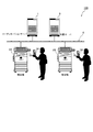
図1は、第1の実施形態に係る機器間連携システム100の構成を概略的に示す。この図1に示すように、機器間連携システム100は、外部機器(本実施形態では、複合機2A,2B)と、コーディネーションサーバ1と、文書サーバ9と、ユーザが保有する携帯電話3A,3Bとを備える。複合機2A,2B、コーディネーションサーバ1、及び文書サーバ9は、LAN6に接続される。なお、外部機器としては、複合機2A、2Bに限らず、パーソナルコンピュータ(PC)、電子ホワイトボード、スキャナ、プリンタ、など様々な機器を採用することができる。
FIG. 1 schematically illustrates the configuration of an
複合機2A、2Bは、紙文書をスキャンする機能や、コピー機能、印刷機能などを有する。これら複合機2A,2Bは、図2に示されるように、メモリ12AとCPU12Bとをそれぞれ有しており、メモリ12Aには、制御プログラムがインストールされる。また、これら複合機2A、2Bには、ユーザが所持する携帯電話3A,3Bとの間で情報通信を行うための識別標識読取書込み機7A、7Bが、USB接続等により接続される。これら識別標識読取書込み機7A,7Bは、図2に示すように、外部から受信したデータを制御プログラムに書き込んだり、制御プログラムからデータを読み込んで外部に送信したりする機能を有する。なお、外部機器として複合機2A,2B以外の機器(PC、電子ホワイトボードなどの機器)を用いる場合にも、上記と同様、これらの機器に対して識別標識読取書込み機を接続する(又は予め識別標識読取書込み機を具備している機器を用いる)必要がある。
The
コーディネーションサーバ1は、複合機2A,2Bそれぞれとの間でデータのやり取りを行うことにより、複合機2A,2B間の接続を確立させるための仲介サーバである。また、このコーディネーションサーバ1は、複合機2A,2Bのスキャン機能により読み込まれた文書イメージを格納することも可能となっている。
The
文書サーバ9は、複合機2A、2Bで共有することが可能なデータ(例えば文書コンテンツなど)を格納するためのサーバである。
The
携帯電話3A,3Bは、図2に示されるように、メモリ13AとCPU13Bとを含んでおり、メモリ13Aには、制御プログラムがインストールされている。また、これら携帯電話3A、3Bには、複合機2A,2Bに接続された識別標識読取書込み機7A、7Bとの間で情報通信を行うための識別標識(ICタグ、RFID(Radio Frequency Identification)など)8A,8Bが設けられている。これら識別標識8A,8Bは、図2に示されるように、外部(識別標識読取書込み機)から受信したデータを制御プログラムに書き込む機能、制御プログラムからデータを読み込んで外部に送信する機能を有する。
As shown in FIG. 2, the
次に、本実施形態の機器間連携システム100が処理するデータ構造について説明する。
Next, a data structure processed by the
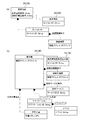
図3(a)は、携帯電話3A,3Bのデータ構造を示す。この図3(a)に示すように、携帯電話3A,3Bは、自局電話番号と連絡先電話番号とを有し、また、携帯電話3A,3Bに設けられた識別標識8A,8Bには、セッションIDが保存される。ここで、セッションIDとは、「発信側の電話番号、受信側の電話番号、日時」から構成されるIDである。
FIG. 3A shows a data structure of the
図3(b)は、複合機2A,2Bのデータ構造を示す。この図3(b)に示すように、複合機2A,2Bは、機器アドレスとセッションIDとコーディネーションサーバのURLとを有することができる。また、複合機2A,2Bは、接続先機器のデータの集合である接続先機器集合と、提供サービスのデータの集合である提供サービス集合と、を有する。これらのうち、接続先機器のデータは、機器アドレスを含み、提供サービスのデータはサービス記述を含む。更に、複合機2A,2BにUSB接続された識別標識読取書込み機7A,7Bは、上述した識別標識から受信したセッションIDのデータを有する。
FIG. 3B shows the data structure of the
図4(a)は、コーディネーションサーバ1のデータ構造を示す。この図4(a)に示すように、コーディネーションサーバ1には、サーバアドレスが設定され、また、コーディネーションサーバ1は、セッションIDと、接続機器データ(機器アドレスを含む)、共有文書データ(文書URLを含む)の集合である共有文書集合、及びアプリケーションデータ(アプリケーション名を含む)を含むイベントプール集合を有する。
FIG. 4A shows the data structure of the
図4(b)は、文書サーバ9のデータ構造を示す。この図4(b)に示すように、文書サーバ9には、サーバアドレスが設定され、また、文書サーバ9は、文書データの集合である文書集合を所持する。文書データには、文書URLと文書(コンテンツ)が含まれる。
FIG. 4B shows the data structure of the
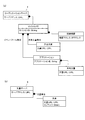
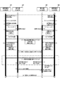
次に、本第1の実施形態の機器間連携システム100における、複合機2A,2B間の連携方法について、図5のシーケンス図(フロー)に沿って、その他の図面を適宜参照しつつ、詳細に説明する。なお、以下の説明で用いる括弧付き数字は、図5で示した処理番号と対応する。
Next, the cooperation method between the
この処理の前提として、携帯電話3Aを保有するユーザが、一方の複合機2Aの近傍に存在し、携帯電話3Bを保有するユーザが、他方の複合機2Bの近傍に存在する。
As a premise of this processing, a user who has the
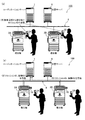
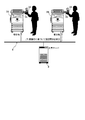
(1)まず、発信側のユーザが携帯電話3Aを用いて、受信側の携帯電話3Bに対して発信し(電話を掛け)、(2)受信側のユーザがその発信に応じて、受信側の携帯電話3Bの通話開始ボタンを押す(電話に出る)ことにより、両ユーザ間における携帯電話3A,3Bを介したコミュニケーション(通話)が開始される(図8(a)の符号(I)参照)。
(1) First, a user on the calling side uses the
(3)次いで、発信側の携帯電話3Aでは、セッションIDを生成する。この場合のセッションIDは、前述したように、「発信側の電話番号、受信側の電話番号、日時」から構成されるIDである。携帯電話3Aは、このセッションIDを、識別標識8Aに対して書き込む(図8(b)の符号(II)参照)。(4)また、同様に、受信側の携帯電話3Bにおいても、「発信側の電話番号、受信側の電話番号、日時」から構成されるセッションIDを生成する。携帯電話3Bは、このセッションIDを、識別標識8Bに対して書き込む(図8(b)の符号(II)参照)。なお、セッションIDは、携帯電話3A,3B間の通話が終了した段階で、識別標識8A,8Bのそれぞれから抹消される。
(3) Next, the originating
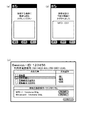
(5)次に、発信側のユーザによって、携帯電話3A(識別標識8A)がユーザ周辺に配置された複合機2Aの識別標識読取書込み機7Aにかざされると、識別標識読取書込み機7Aが識別標識8Aから「セッションID送信メッセージ」を受信する。なお、識別標識8Aを識別標識読取書込み機7Aにかざす場合、実際には、携帯電話3Aを操作して、その画面上に、図6(a)に示すようなメッセージを表示する必要がある。
(5) Next, when the
ここで、識別標識読取書込み機7Aが受信したセッションID送信メッセージは、「メッセージID、セッションID」から構成されている。したがって、このセッションID送信メッセージを識別標識読取書込み機7Aが受信することにより、複合機2Aには、上述した(3)の処理において生成されたセッションIDが受け渡されることになる(図9(a)の符号(III)参照)。なお、複合機2Aは、携帯電話3AからセッションID送信メッセージを、常時受信することが可能な状態(待機状態)となっており、また、複合機2Aでは、セッションID送信メッセージを受信した段階で、携帯電話3Aに対して、「セッションID受信完了メッセージ(返信対象メッセージを含む)」を送り返す。この場合に、セッションID受信完了メッセージを受信した携帯電話3Aでは、図6(b)に示すような表示(複合機2Aの名称である「MFD−001」の表示)がなされるようになっている。
Here, the session ID transmission message received by the identification mark reader /
(6)また、受信側においても同様に、ユーザにより、携帯電話3B(識別標識8B)がユーザ周辺に配置された複合機2Bの識別標識読取書込み機7Bにかざされると、携帯電話3B側から複合機2B側に、「セッションID送信メッセージ」が送信される。このセッションID送信メッセージは、「メッセージID、セッションID」から構成されているため、当該メッセージの送信により、複合機2Bには、上述した(4)の処理において生成されたセッションIDが受け渡されることになる(図9(a)の符号(III)参照)。なお、複合機2Bも、セッションID送信メッセージを常時受信することが可能な状態(待機状態)に設定されている。また、複合機2Bでは、セッションID送信メッセージを受信した段階で、携帯電話3Bに対して、「セッションID受信完了メッセージ(返信対象メッセージを含む)」を送り返す。
(6) Similarly, on the receiving side, when the user holds the
(7)次いで、発信側の複合機2Aは、携帯電話3AからセッションIDを受信した段階で、「登録依頼メッセージ」をコーディネーションサーバ1に送信する。ここで、登録依頼メッセージは、「メッセージID、セッションID、機器ID」から構成されているため、当該メッセージの送信により、コーディネーションサーバ1には、セッションIDと機器IDとが受け渡されることになる。なお、「機器ID」としては、機器(複合機2A)のIPアドレスやIPアドレスからハッシュ関数等により算出される値(例えば、暗号化等で一般に利用されるSHA−256等のアルゴリズムによって計算される値)を用いることができる。
(7) Next, the originating
(8)受信側の複合機2Bにおいても、送信側の複合機2Aと同様、携帯電話3BからセッションIDを受信した段階で、「登録依頼メッセージ(「メッセージID、セッションID、機器ID」から構成されている)」をコーディネーションサーバ1に送信する。
(8) The reception side
(9)このようにして、複合機2A、2BからセッションIDと機器IDとを受信したコーディネーションサーバ1は、そのセッションIDと機器IDとを登録(蓄積)する(図9(b)の符号(IV)参照)。コーディネーションサーバ1では、この登録(蓄積)が完了した段階で、各複合機2A,2Bに対して、「登録完了メッセージ(返信対象メッセージを含む)」を送信する。
(9) In this way, the
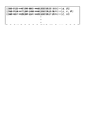
(10)その後、複合機2A、2Bは、「機器リスト取得依頼メッセージ(メッセージIDを含んでいる)」を定期的にコーディネーションサーバ1に送信して問い合わせを行い、コーディネーションサーバ1は、これに応じて、「機器リスト取得返信メッセージ」を、複合機2A,2Bに対して送信する。この機器リスト取得返信メッセージは、返信対象メッセージIDと機器ID集合(機器リスト)とを含む。ここで、機器ID集合(機器リスト)は、図7に示すように、「{セッションID}→{機器IDの組み合わせ}」により構成される。換言すると、機器ID集合(機器リスト)が、セッションIDに含まれる電話番号の携帯電話に対して、対応付けられた状態となっているということができる。すなわち、処理(10)では、メッセージのやり取りによって、セッションIDに対応付けられた機器リストを取得することができるようになっている(図10(a)の符号(V)参照)。なお、図7では、携帯電話3Aの電話番号が(090−0123−**67)として示され、携帯電話3Bの電話番号が(090−8901−**45)として示され、複合機2Aの機器IDがα、複合機2Bの機器IDがβとして示される。
(10) After that, the
(11)次いで、複合機2A,2Bは、上記(10)の処理にて取得した機器ID集合(機器リスト)に基づいて、複合機2A、2B間のP2P(Peer to Peer)接続を実行する(図10(b)の符号(VI)参照)。
(11) Next, the
ここで、P2P接続は、複合機2A,2B間での、(i)文書一覧の共有、(ii)共有文書に対する操作イベントの共有によって実現される。
Here, the P2P connection is realized by (i) sharing the document list and (ii) sharing the operation event for the shared document between the
具体的には、コーディネーションサーバ1には、セッションIDに対応して、複合機2A,2Bを用いた共同作業で共有される文書(文書URL)の集合が保持される。すなわち、例えば、複合機2Aでスキャンされた文書(文書URL)や、文書サーバ9内の文書集合に含まれる文書(文書URL)などが保持される。
Specifically, the
したがって、例えば、複合機2Aで文書(例えば「見積書案1」であるものとする)をスキャンした場合には、複合機2A,2Bの画面(タッチパネル)上に表示される共有文書リストの中に、図6(c)に示されるようにして、見積書案1が追加される(なお、実際には、文書名はユーザが入力する必要がある)。この場合、「見積書案1」のファイル自体は、コーディネーションサーバ1に格納される。
Therefore, for example, when a document (for example, “
そして、複合機2Aの画面上において、「見積書案1」が選択され、複合機2B(図6(c)では、複合機2Bが、「MFD−11 Yokohama.bldg」として示されている)が呼び出され、かつ、共有操作として「印刷」が選択されると、コーディネーションサーバ1は、セッションIDとアプリケーション集合に対応付けて設けられたイベントプール(複合機2A,2Bに対するユーザによる操作に伴って発生する操作イベントを蓄積する。図4(a)参照)を蓄積する。これに対し、複合機2Bにおいて、当該操作イベントを呼び出すことで、複合機2Bにおける見積書案1の印刷を実行することができる。このようにして、複合機2A近傍に存在するユーザと、複合機2B近傍に存在するユーザは、複合機に何らかの情報(ファックス番号など)を手入力したりすること無く、複合機2A,2Bを用いて見積書案1を共有することが可能である。
Then, on the screen of the
なお、上記においては、P2P接続される外部機器として、2台の複合機を採用した場合について説明したが、これに限られるものではなく、P2P接続される外部機器として、2台のPCを採用することが可能である。この場合、例えば、一方のPCのユーザにより、PCに登録されたアプリケーションを用いて文書に対する操作が行われると、PCは、その操作イベントをコーディネーションサーバ1に送信し、コーディネーションサーバ1は、受信した操作イベントを、イベントプールに蓄積する。なお、この場合の操作イベントは、{操作イベントID、操作日時、操作対象文書、操作名、オプション集合}から構成されている。
In the above description, the case where two multi-function peripherals are adopted as external devices connected to P2P has been described. However, the present invention is not limited to this, and two PCs are adopted as external devices connected to P2P. Is possible. In this case, for example, when a user of one PC performs an operation on a document using an application registered in the PC, the PC transmits the operation event to the
そして、新しい操作イベントがコーディネーションサーバ1のイベントプールに追加されると、操作イベントの情報は、他方のPCのアプリケーションに通知され、これを受信した他方のPCのアプリケーションでは、文書に対して、当該操作イベントの情報に対応した処理を実行する。
Then, when a new operation event is added to the event pool of the
より具体的には、一方のPCにおいて、あるアプリケーションを利用して文書ファイルのオープンが実行されると、その操作イベントがコーディネーションサーバ1のイベントプールに登録される。そして、コーディネーションサーバ1から他方のPC上で実行されているアプリケーションプログラムに対して、当該操作イベントが通知され、他方のPC上で、一方のPC上で行われた操作と同一の操作(文書ファイルのオープン)が実行される。このようにすることで、接続関係にある各PC上のアプリケーションの動作を同期させることが可能となる。
More specifically, when a document file is opened using a certain application in one PC, the operation event is registered in the event pool of the
また、P2P接続される機器が、例えば、複合機とPCであった場合には、ユーザは、PC上で複合機の「操作インタフェース」を呼び出して、コーディネーションサーバ1が保持する共有文書集合中の文書に対して印刷や表示などの操作を実行したり、スキャン等の操作した結果を共有文書集合に格納したりする。なお、この場合、複合機は、当該複合機の操作をWebブラウザ上で行うことを可能にする操作インタフェースを、LAN上に公開し、PC等に提供する必要がある。
Further, when the P2P-connected devices are, for example, a multifunction device and a PC, the user calls the “operation interface” of the multifunction device on the PC, and in the shared document set held by the
図5に戻り、複合機2A,2B間では、定期的に、機器リストが更新されているか否かを確認する処理が実行される。具体的には、図5において一点鎖線にて囲まれた部分から分かるように、(12)の処理において、複合機2A、2Bがコーディネーションサーバ1に対して新規追加機器の有無を確認するためのメッセージを送信し、(13)の処理において、コーディネーションサーバ1が、セッションIDに対応付けられている機器リストを含むメッセージを返信し、更に、(14)の処理において、複合機2A,2Bが、受信した機器リストに、新規追加機器があると判断した場合には、上述した処理(11)と同様に、新規追加機器との間でP2P接続を行う処理を、所定時間間隔で実行する。
Returning to FIG. 5, processing for confirming whether or not the device list has been updated is periodically executed between the
(15)その後、ユーザ間のコミュニケーションが終了すると、ユーザにより、一方の複合機(例えば複合機2A)の画面(タッチパネル)上で、終了ボタンが押されるが、複合機2Aでは、コーディネーションサーバ1に対して終了依頼メッセージを送信し、(16)コーディネーションサーバ1では、複合機2A,2Bに対して終了を通知する。そして、(17)各複合機2A,2Bでは、終了通知を検出した時点でP2P接続を切断する。
(15) Thereafter, when the communication between the users ends, the user presses an end button on the screen (touch panel) of one of the multifunction devices (for example, the
(18)その後、ユーザにより、携帯電話の通話が切断されることにより、図5の処理が終了するようになっている。 (18) Thereafter, when the user disconnects the cellular phone call, the processing in FIG. 5 ends.
以上詳細に説明したように、本第1の実施形態によると、携帯電話3A,3Bが、外部機器(複合機2A,2B)に対して携帯電話3A,3Bに関する情報(電話番号)を含むコミュニケーション情報(セッションID)を送信し、コーディネーションサーバ1が、外部機器から送信されるセッションIDと、機器IDとに基づいて、外部機器それぞれに対して接続相手となるべき外部機器の情報を送信し、各外部機器は、コーディネーションサーバ1から受信した情報に基づいて、LAN6上での接続関係を確立する(P2P接続する)ので、ユーザが携帯電話3A,3Bによりコミュニケーションを行っている間に、携帯電話をかざすことにより取得したデータを用いて、外部機器(複合機2A,2B)同士をP2P接続することが可能である。これにより、外部機器を用いた資料等に対する共同作業環境がアドホックに提供されるので、各ユーザは、外部機器上で資料等を共有した状態で、携帯電話3A,3Bを用いたコミュニケーションを図ることができる。
As described above in detail, according to the first embodiment, the
また、本第1の実施形態では、コーディネーションサーバ1(又は文書サーバ9)に、外部機器において利用可能なコンテンツデータ(複合機でスキャンした文書イメージデータや、文書ファイル)が格納されており、外部機器間がP2P接続されている状態で、両外部機器においてコンテンツデータが共有されるので、ユーザは、コンテンツデータに対する外部機器を用いた共同作業を行いながら、携帯電話3A,3Bを用いたコミュニケーションを図ることができる。
In the first embodiment, the coordination server 1 (or the document server 9) stores content data (document image data and document files scanned by a multifunction machine) that can be used in an external device. Since the content data is shared between the two external devices in a state where the devices are P2P connected, the user can perform communication using the
また、本第1の実施形態では、コンテンツデータに対する各外部機器からの操作情報(操作イベント)が蓄積され、各外部機器では、操作情報に基づいて、コンテンツデータに対する同一の操作が行われるので、一方の外部機器において行われるコンテンツデータに対する操作を、両外部機器において共有することが可能となる。 Further, in the first embodiment, operation information (operation event) from each external device for content data is accumulated, and each external device performs the same operation on the content data based on the operation information. The operation on the content data performed in one external device can be shared by both external devices.
また、本第1の実施形態では、コーディネーションサーバ1による機器リストの更新が、所定時間間隔で実行されるので、外部機器の接続関係を適切なタイミングで見直すことが可能となる。
In the first embodiment, since the device list is updated by the
なお、上記第1の実施形態では、機器間連携システムが文書サーバ9を備えている場合について説明したが、これに限られるものではなく、文書サーバ9を設けないこととしても良い。この場合、外部機器(複合機やPC、電子ホワイトボードなど)やコーディネーションサーバ1のメモリに、文書ファイルなどを格納しておき、その文書ファイルを複数の外部機器において共有するようにしても良い。
In the first embodiment, the case where the inter-device cooperation system includes the
また、上記第1の実施形態では、携帯電話(3A,3B)と外部機器(2A,2B)との間でセッションIDを交換する場合について説明したが、これに限られるものではなく、セッションIDの交換を行わなくても良い。この場合、例えば、携帯電話3A,3Bでの通話の開始と同時に、携帯電話3A,3B内で発信先電話番号と受信先電話番号で特定されるセッションIDを生成し、コーディネーションサーバ1に保存しておき、携帯電話3A,3Bの電話番号と、ユーザの生体識別ID(またはユーザが予め登録しておいたユーザ名とパスワード)とを予め対応付けておく。そして、ユーザが利用する外部機器において当該生体識別ID(またはユーザ名とパスワード)が認識(入力)された段階で、当該外部機器が、その生体識別ID(またはユーザ名とパスワード)に対応するセッションIDの情報を検索し、発見した場合には、外部機器のエントリにその外部機器のIPアドレスを登録することで、その情報に基づいて機器間のアドホックな機器連携を実現するようにすることができる。
In the first embodiment, the case where the session ID is exchanged between the mobile phone (3A, 3B) and the external device (2A, 2B) has been described. However, the present invention is not limited to this. It is not necessary to exchange In this case, for example, simultaneously with the start of a call on the
《第2の実施形態》
次に、本発明の機器間連携システムの第2の実施形態について、図11〜図17に基づいて詳細に説明する。図11には、第2の実施形態に係る機器間連携システム100’の構成が示されている。この図11と上記第1の実施形態の構成(図1)を比較すると分かるように、本第2の実施形態の機器間連携システム100’には、コーディネーションサーバ1が設けられていない点に特徴を有している。
<< Second Embodiment >>
Next, a second embodiment of the inter-device cooperation system of the present invention will be described in detail based on FIGS. FIG. 11 shows a configuration of an
また、携帯電話3A,3Bが、携帯電話間で無線ネットワーク経由でのデータ通信を行う機能を有するIP携帯電話である点が、第1の実施形態と異なっている。
The
ここで、図12〜図13を参照しつつ、本第2の実施形態の機器間連携システム100’が処理するデータ構造について説明する。
Here, a data structure processed by the
図12(a)には、携帯電話3A,3Bのデータ構造が示されている。この図12(a)に示されるように、携帯電話3A,3Bは、自局電話番号と連絡先電話番号とを有し、また、携帯電話3A,3Bに設けられた識別標識8A,8Bには、セッションIDが保存される。ここで、セッションIDとは、第1の実施形態と同様、「発信側の電話番号、受信側の電話番号、日時」から構成されるIDである。このセッションIDは、セッションIDデータとして携帯電話3A,3Bにも保持され、また、携帯電話3A,3Bは、セッションIDデータに対応して、接続機器データ(機器アドレスを含む)の集合である接続機器集合をも保持する。
FIG. 12A shows the data structure of the
図12(b)は、複合機2A,2Bのデータ構造を示す。この図12(b)に示すように、複合機2A,2Bは、機器アドレスを有する。また、複合機2A,2Bは、接続先機器のデータ(機器アドレス)の集合である接続先機器集合と、提供サービスのデータ(サービス記述)の集合である提供サービス集合と、アプリケーションデータ(アプリケーション名)及びこれに関連したイベントの集合であるイベントプールを含むイベントプール集合と、共有文書のデータ(文書URL)の集合である共有文書集合と、を有する。更に、複合機2A,2BにUSB接続された識別標識読取書込み機7A,7Bは、上述した識別標識8A,8Bから受信したセッションIDのデータを有する。
FIG. 12B shows the data structure of the
図13は、文書サーバ9のデータ構造を示す。この図13に示すように、文書サーバ9には、サーバアドレスが設定されており、また、文書サーバ9は、文書データの集合である文書集合を所持する。文書データには、文書URLと文書(コンテンツ)が設定されている。
FIG. 13 shows the data structure of the
次に、本第2の実施形態の機器間連携システム100’における、複合機2A,2B間の連携方法について、図14のシーケンス図(フロー)に沿って、その他の図面を適宜参照しつつ、詳細に説明する。なお、以下の説明で用いる括弧付き数字は、図14で示した処理番号と対応付けられたものである。
Next, regarding the cooperation method between the
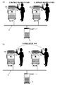
(1)まず、発信側のユーザが携帯電話3Aを用いて、受信側の携帯電話3Bに対して発信し(電話を掛け)、(2)受信側のユーザがその発信に応じて、受信側の携帯電話3Bの通話開始ボタンを押す(電話に出る)ことにより、両ユーザ間における携帯電話3A,3Bを介したコミュニケーション(通話)が開始される(図15(a)の符号(I)参照)。
(1) First, a user on the calling side uses the
(3)次いで、発信側の携帯電話3Aでは、セッションIDを生成する。この場合のセッションIDは、前述したように、「発信側の電話番号、受信側の電話番号、日時」から構成されるIDである。携帯電話3Aは、このセッションIDを、識別標識8Aに対して書き込む。(4)また、同様に、受信側の携帯電話3Bにおいても、「発信側の電話番号、受信側の電話番号、日時」から構成されるセッションIDを生成する。携帯電話3Bは、このセッションIDを、識別標識8Bに対して書き込む。なお、セッションIDは、携帯電話3A,3B間の通話が終了した段階で、識別標識8A,8Bのそれぞれから抹消される。
(3) Next, the originating
(5)次に、通話中の発信側のユーザにより、携帯電話3A(識別標識8A)がユーザ周辺に配置された複合機2Aの識別標識読取書込み機7Aにかざされると、識別標識読取書込み機7Aが識別標識8Aから「セッションID送信メッセージ」を受信する。ここで、識別標識読取書込み機7Aが受信したセッションID送信メッセージは、「メッセージID、セッションID」から構成される。したがって、このセッションID送信メッセージを識別標識読取書込み機7Aが受信することにより、複合機2Aには、上述した(3)の処理において生成されたセッションIDが受け渡されることになる。(6)また、これに対し、複合機2Aからは、携帯電話3Aに対して、「セッションID受信完了メッセージ(返信対象メッセージを含む)」を送り返すとともに、「機器ID送信メッセージ」を送信する。この機器ID送信メッセージは、「メッセージID,機器ID」から構成されるので、当該メッセージの送信により、携帯電話3Aに対して機器IDが送信されることになる(図15(b)の符号(II)参照)。
(5) Next, when the
(7)そして、携帯電話3Aにおいて機器IDが受信されると、(8)携帯電話3Aは、複合機2Aに対して「機器ID受信完了メッセージ(返信対象メッセージを含む)」を送り返すとともに、複合機2Aとの間で、P2P接続を行う(図16(a)の符号(III)参照)。
(7) When the device ID is received by the
上記と同様に、携帯電話3B及び複合機2Bにおいても、図14の処理(9)〜(12)において、セッションIDと機器IDのやり取りを行うとともに、携帯電話3B、複合機2B間でのP2P接続を確立する(図16(a)の符号(III)参照)。
Similarly to the above, in the
(13)次いで、携帯電話3A,3B間では、各携帯電話が有する機器IDの集合のやり取りを行うことにより、機器IDを共有する(図16(b)の符号(IV)参照)。
(13) Next, between the
(14)その後、携帯電話3Aでは、接続対象の機器IDの集合を複合機2Aに対してP2P接続を介して送信するとともに、他の機器(ここでは複合機2B)への接続依頼メッセージを送信する。(15)これと同様に、携帯電話3BでもP2P接続を介して複合機2Bに対して接続対象の機器IDの集合を送信するとともに、他の機器(ここでは複合機2A)への接続依頼メッセージを送信する。
(14) Thereafter, the
(16)このようにして、互いの機器IDを取得した複合機2Aと複合機2Bは、機器IDに基づいて両複合機2A,2BのP2P接続を確立させる(図17の符号(V)参照)。
(16) In this way, the
P2P接続が確立した複合機2A,2B間での文書の共有、共有文書に対する操作イベントの共有については、共有文書や、操作イベントが、複合機2A,2Bのメモリに記憶される点を除いて、上記第1の実施形態と同様である。
Regarding the sharing of documents between the
なお、本第2の実施形態においても、携帯電話3A,3B間では、定期的に、機器リストが更新されているか否かを確認する処理を実行する。具体的には、図14において一点鎖線にて囲まれた部分から分かるように、(17)の処理において、携帯電話3A、3B相互間で、新規追加機器の有無を確認する。そして、(18)の処理において、新規追加機器があると判断した場合には、新規追加機器との間でP2P接続を行う処理を実行する。
In the second embodiment as well, a process of periodically checking whether or not the device list is updated is executed between the
(19)その後、ユーザ間のコミュニケーションが終了すると、ユーザにより、一方の複合機(例えば複合機2A)の画面(例えばタッチパネル)上で、終了ボタンが押され、複合機2Aでは、複合機2Bに対して終了通知を行う。そして、(20)複合機2Bでは、終了通知を検出した時点でP2P接続を切断する。
(19) After that, when the communication between the users ends, the user presses an end button on the screen (for example, touch panel) of one of the multifunction devices (for example, the
(21)そして、ユーザにより、携帯電話の通話が切断されることにより、図14の処理が終了する。 (21) When the user disconnects the cellular phone call, the processing in FIG. 14 ends.
以上詳細に説明したように、本第2の実施形態によると、無線ネットワーク経由でデータ通信を行う機能を有する携帯電話(IP携帯電話)3A,3Bが、外部機器(複合機2A,2B)から当該外部機器に関する情報(機器ID)を受信するとともに、データ通信が可能な状態で携帯電話3A,3Bと外部機器との間が接続(P2P接続)され、両外部機器は、両携帯電話3A,3B間で共有している機器IDに基づいてP2P接続を確立する。これにより、ユーザが、携帯電話3A,3Bにより通話(コミュニケーション)を行っているときに、当該コミュニケーションを行っているユーザそれぞれが携帯電話をかざした外部機器同士をP2P接続することが可能である。これにより、外部機器を用いた資料等に対する共同作業環境がアドホックに提供されるので、各ユーザは、外部機器上で資料等を共有した状態で、携帯電話3A,3Bを用いたコミュニケーションを行うことができる。
As described above in detail, according to the second embodiment, mobile phones (IP mobile phones) 3A and 3B having a function of performing data communication via a wireless network are transferred from external devices (
また、本第2の実施形態では、コーディネーションサーバを用いないことから、第1の実施形態に比べて、機器間連携システムを構成する必要最小限の装置数を低減することが可能である。 In the second embodiment, since no coordination server is used, it is possible to reduce the minimum necessary number of devices constituting the inter-device cooperation system as compared to the first embodiment.
なお、上記第2の実施形態では、機器間連携システム100’に文書サーバ9を設けることとしたが、これに限られるものではなく、文書サーバ9については設けなくても良い。この場合、外部機器(複合機やPC、電子ホワイトボードなど)のメモリに、文書ファイルなどを格納しておき、その文書ファイルを複数の外部機器において共有しても良い。
In the second embodiment, the
なお、上記第2の実施形態では、携帯電話においてセッションIDを生成することとしたが、これに限らず、外部機器においてセッションIDを生成しても良い。 In the second embodiment, the session ID is generated in the mobile phone. However, the present invention is not limited to this, and the session ID may be generated in the external device.
なお、上記各実施形態では、セッションIDとして、携帯電話3A,3Bの電話番号を含むセッションIDを採用することとしたが、これに限らず、セッションIDとして、電話番号以外、例えば携帯電話に設定されたIPアドレスや、機器番号などを含むセッションIDを採用しても良い。
In each of the above embodiments, the session ID including the phone numbers of the
なお、上記各実施形態では、識別標識及び識別標識読取書込み機を用いて携帯電話3A,3Bと外部機器との間で情報のやり取りを行ったが、これに限らず、赤外線通信や、無線通信、音声(超音波)、電子メールなどを利用して、情報のやり取りを行っても良い。
In each of the above-described embodiments, information is exchanged between the
なお、上記実施形態では、識別標識を有する携帯電話を使用した例について説明したが、これに限られるものではなく、識別標識を有する携帯電話以外の携帯情報端末(PDAやスマートフォンなど)を使用することとしても良い。また、通信に識別標識以外の手段(赤外線等)を用いる場合には、これら携帯情報端末が識別標識を有しなくても良い。 In the above-described embodiment, an example in which a mobile phone having an identification mark is used has been described. However, the present invention is not limited to this, and a portable information terminal (such as a PDA or a smartphone) other than a mobile phone having an identification mark is used. It's also good. Moreover, when using means other than an identification mark (infrared rays or the like) for communication, these portable information terminals do not have to have an identification mark.
また、上記各実施形態では、2台の外部機器同士を接続する場合について説明したが、これに限られるものではなく、ユーザは、複数の機器において携帯電話(またはユーザのID)を認識させることにより、3以上の機器間を接続することができる。 Further, in each of the above embodiments, a case where two external devices are connected to each other has been described. However, the present invention is not limited to this, and the user is allowed to recognize a mobile phone (or a user ID) in a plurality of devices. Thus, three or more devices can be connected.
上述した実施形態は本発明の好適な実施の例である。但し、これに限定されるものではなく、本発明の要旨を逸脱しない範囲内において種々変形実施可能である。 The above-described embodiment is an example of a preferred embodiment of the present invention. However, the present invention is not limited to this, and various modifications can be made without departing from the scope of the present invention.
1 コーディネーションサーバ(サーバの一部)
2A,2B 複合機(情報機器)
3A,3B 携帯電話(携帯情報端末)
6 LAN(ネットワーク)
7A,7B 識別標識読取書込み機
8A,8B 識別標識
9 文書サーバ(サーバの一部)
1 Coordination server (part of the server)
2A, 2B MFP (information equipment)
3A, 3B mobile phones (portable information terminals)
6 LAN (network)
7A, 7B Identification sign reader /
Claims (14)
前記他の携帯情報端末に対してコミュニケーション可能に接続された状態の前記一の携帯情報端末から、前記両携帯情報端末に関する情報を含むコミュニケーション情報を取得する、ネットワークに接続された一の情報機器と、
前記一の携帯情報端末に対してコミュニケーション可能に接続された状態の前記他の携帯情報端末から、前記コミュニケーション情報を取得する、前記ネットワークに接続された他の情報機器と、
前記コミュニケーション情報と、前記一の情報機器に関する情報及び前記他の情報機器に関する情報とを登録し、これらの情報に基づいて、前記一の情報機器に対して、前記他の情報機器に関する情報を前記ネットワーク経由で送信するとともに、前記他の情報機器に対して、前記一の情報機器に関する情報を前記ネットワーク経由で送信するサーバと、を備え、
前記一の情報機器と前記他の情報機器は、前記サーバから受信した情報に基づいて、前記ネットワーク上での接続関係を確立することを特徴とする機器間連携システム。 One portable information terminal and another portable information terminal used for communication between users;
An information device connected to a network for acquiring communication information including information relating to the two portable information terminals from the one portable information terminal in a state of being communicably connected to the other portable information terminal; ,
Other information devices connected to the network that acquire the communication information from the other portable information terminal that is connected to be communicable with the one portable information terminal;
The communication information, the information related to the one information device, and the information related to the other information device are registered, and the information related to the other information device is registered to the one information device based on the information. A server that transmits the information about the one information device to the other information device via the network.
The inter-device cooperation system, wherein the one information device and the other information device establish a connection relationship on the network based on information received from the server.
前記両情報機器の間に接続関係が確立している状態で、当該両情報機器において、前記コンテンツデータが共有されることを特徴とする請求項1に記載の機器間連携システム。 The server stores content data that can be used in both information devices,
The inter-device cooperation system according to claim 1, wherein the content data is shared between the two information devices in a state where a connection relationship is established between the two information devices.
前記両情報機器では、前記操作情報に基づいて、前記コンテンツデータに対する同一の操作が行われることを特徴とする請求項2に記載の機器間連携システム。 The server stores operation information from the information devices for the content data,
The inter-device cooperation system according to claim 2, wherein the two information devices perform the same operation on the content data based on the operation information.
前記携帯電話機それぞれから前記各情報機器に対して送信されるコミュニケーション情報には、前記両携帯電話機の電話番号が含まれることを特徴とする請求項1〜3のいずれか一項に記載の機器間連携システム。 The portable information terminal is a mobile phone;
The communication information transmitted from each of the mobile phones to each of the information devices includes the phone numbers of both the mobile phones. Cooperation system.
前記両情報機器のうちのいずれかから送信された終了情報を受信したサーバによる指示の下、実行されることを特徴とする請求項1〜5のいずれか一項に記載の機器間連携システム。 Termination of the connection between the two information devices
The inter-device cooperation system according to any one of claims 1 to 5, wherein the inter-device cooperation system is executed under an instruction from a server that has received end information transmitted from either of the two information devices.
ユーザ間におけるコミュニケーションに用いられ、前記ネットワークとは異なる無線ネットワーク経由で互いにデータ通信する機能を有し、前記情報機器のそれぞれから、当該各情報機器に関する情報をそれぞれ受信する一の携帯情報端末及び他の携帯情報端末と、を備え、
前記一の携帯情報端末とこれに情報を送信した情報機器との間、及び前記他の携帯情報端末とこれに情報を送信した情報機器との間が、データ通信可能な状態で接続され、
前記両携帯情報端末間は、それぞれが受信した情報機器に関する情報を互いに送受信して、共有し、
前記両情報機器は、前記両携帯情報端末が共有する前記情報機器に関する情報に基づいて、前記ネットワーク内での接続関係を確立することを特徴とする機器間連携システム。 One information device and other information devices connected via a network;
One portable information terminal used for communication between users, having a function of performing data communication with each other via a wireless network different from the network, and receiving information related to each information device from each of the information devices, and others Mobile information terminal, and
Between the one portable information terminal and the information device that has transmitted information thereto, and between the other portable information terminal and the information device that has transmitted information to the information device are connected in a state capable of data communication,
Between the two portable information terminals, each transmits and receives information on information devices received by each other, and shares,
The both information devices establish a connection relationship in the network based on information on the information devices shared by the two portable information terminals.
前記両情報機器は、前記コミュニケーション情報にも基づいて、前記ネットワーク内での接続関係を確立することを特徴とする請求項7に記載の機器間連携システム。 Each portable information terminal, when receiving information about each information device, transmits communication information including information about both portable information terminals to each information device,
8. The inter-device cooperation system according to claim 7, wherein the two information devices establish a connection relationship in the network based on the communication information.
前記携帯情報端末と前記情報機器との間の情報の送受信は、前記識別標識を介して行われることを特徴とする請求項1〜12のいずれか一項に記載の機器間連携システム。 The portable information terminal has an identification mark,
The inter-device cooperation system according to any one of claims 1 to 12, wherein transmission / reception of information between the portable information terminal and the information device is performed via the identification mark.
Priority Applications (1)
| Application Number | Priority Date | Filing Date | Title |
|---|---|---|---|
| JP2007269075A JP2009100191A (en) | 2007-10-16 | 2007-10-16 | Coordination system among devices |
Applications Claiming Priority (1)
| Application Number | Priority Date | Filing Date | Title |
|---|---|---|---|
| JP2007269075A JP2009100191A (en) | 2007-10-16 | 2007-10-16 | Coordination system among devices |
Publications (2)
| Publication Number | Publication Date |
|---|---|
| JP2009100191A true JP2009100191A (en) | 2009-05-07 |
| JP2009100191A5 JP2009100191A5 (en) | 2010-11-25 |
Family
ID=40702784
Family Applications (1)
| Application Number | Title | Priority Date | Filing Date |
|---|---|---|---|
| JP2007269075A Withdrawn JP2009100191A (en) | 2007-10-16 | 2007-10-16 | Coordination system among devices |
Country Status (1)
| Country | Link |
|---|---|
| JP (1) | JP2009100191A (en) |
Cited By (2)
| Publication number | Priority date | Publication date | Assignee | Title |
|---|---|---|---|---|
| JP2011223506A (en) * | 2010-04-14 | 2011-11-04 | Kddi Corp | Display system, display method and program |
| US20170249114A1 (en) * | 2016-02-25 | 2017-08-31 | Konica Minolta, Inc. | Information terminal, image processing system, and program |
-
2007
- 2007-10-16 JP JP2007269075A patent/JP2009100191A/en not_active Withdrawn
Cited By (5)
| Publication number | Priority date | Publication date | Assignee | Title |
|---|---|---|---|---|
| JP2011223506A (en) * | 2010-04-14 | 2011-11-04 | Kddi Corp | Display system, display method and program |
| US20170249114A1 (en) * | 2016-02-25 | 2017-08-31 | Konica Minolta, Inc. | Information terminal, image processing system, and program |
| JP2017151790A (en) * | 2016-02-25 | 2017-08-31 | コニカミノルタ株式会社 | Information terminal, image processing system, and program |
| CN107122144A (en) * | 2016-02-25 | 2017-09-01 | 柯尼卡美能达株式会社 | Information terminal, image processing system and program |
| US10871928B2 (en) | 2016-02-25 | 2020-12-22 | Konica Minolta, Inc. | Information terminal with a calling unit configured to enable communication with another information terminal, image processing system, and program |
Similar Documents
| Publication | Publication Date | Title |
|---|---|---|
| JP2003084945A (en) | Data transmitting/receiving system, data transmitting device, and image forming device | |
| JP2009098903A (en) | Information equipment system | |
| JP2021064919A (en) | Image forming apparatus, receipt notification system, receipt notification method, and program | |
| JP6014562B2 (en) | Image forming apparatus | |
| KR101091520B1 (en) | Printing-cumunication complex service system | |
| JP2007081652A (en) | Shared information processing apparatus with transmission function and image forming apparatus | |
| JP2013164836A (en) | Information processing system, network system and information processing method | |
| JP2017108338A (en) | Information processing device, information processing device control method, mobile terminal, mobile terminal control method, and program | |
| JP2005057549A (en) | Mfp system, server, remote operating method, and program | |
| JP2014093765A (en) | Image information communication apparatus, image information communication system, control method of image information communication apparatus, and control program of image information communication apparatus | |
| JP2009100191A (en) | Coordination system among devices | |
| JP4760255B2 (en) | Network printing system | |
| JP5007642B2 (en) | E-mail delivery system | |
| JP4465302B2 (en) | Image forming apparatus and image forming system | |
| JP2007067712A (en) | Network print system, image forming apparatus and image data history managing program | |
| JP2020184801A (en) | Information processing device and control method of the same | |
| JP2002196900A (en) | Image forming system | |
| KR101786046B1 (en) | Method for providing cloud printing service, apparatus and system for performing the same | |
| JP2009088876A (en) | Information processing system | |
| JP2007111920A (en) | Image forming apparatus and program | |
| JP2009129120A (en) | Information communication system | |
| KR20150037384A (en) | System and method for providing printing service based on phone number | |
| JP2019213087A (en) | Image processing device, information processing method, and program | |
| JP7135172B2 (en) | Information processing device and information processing device control method | |
| JP2007221709A (en) | Network image input/output system and image formation apparatus |
Legal Events
| Date | Code | Title | Description |
|---|---|---|---|
| A521 | Written amendment |
Free format text: JAPANESE INTERMEDIATE CODE: A523 Effective date: 20101006 |
|
| A621 | Written request for application examination |
Free format text: JAPANESE INTERMEDIATE CODE: A621 Effective date: 20101006 |
|
| A761 | Written withdrawal of application |
Free format text: JAPANESE INTERMEDIATE CODE: A761 Effective date: 20111007 |