JP2009090111A - Surgical portal with foam and fabric composite seal assembly - Google Patents
Surgical portal with foam and fabric composite seal assembly Download PDFInfo
- Publication number
- JP2009090111A JP2009090111A JP2008259101A JP2008259101A JP2009090111A JP 2009090111 A JP2009090111 A JP 2009090111A JP 2008259101 A JP2008259101 A JP 2008259101A JP 2008259101 A JP2008259101 A JP 2008259101A JP 2009090111 A JP2009090111 A JP 2009090111A
- Authority
- JP
- Japan
- Prior art keywords
- seal
- surgical
- segment
- foam
- portal assembly
- Prior art date
- Legal status (The legal status is an assumption and is not a legal conclusion. Google has not performed a legal analysis and makes no representation as to the accuracy of the status listed.)
- Pending
Links
Images


Classifications
-
- A—HUMAN NECESSITIES
- A61—MEDICAL OR VETERINARY SCIENCE; HYGIENE
- A61B—DIAGNOSIS; SURGERY; IDENTIFICATION
- A61B17/00—Surgical instruments, devices or methods, e.g. tourniquets
- A61B17/34—Trocars; Puncturing needles
- A61B17/3462—Trocars; Puncturing needles with means for changing the diameter or the orientation of the entrance port of the cannula, e.g. for use with different-sized instruments, reduction ports, adapter seals
-
- A—HUMAN NECESSITIES
- A61—MEDICAL OR VETERINARY SCIENCE; HYGIENE
- A61B—DIAGNOSIS; SURGERY; IDENTIFICATION
- A61B17/00—Surgical instruments, devices or methods, e.g. tourniquets
- A61B2017/00831—Material properties
-
- A—HUMAN NECESSITIES
- A61—MEDICAL OR VETERINARY SCIENCE; HYGIENE
- A61B—DIAGNOSIS; SURGERY; IDENTIFICATION
- A61B17/00—Surgical instruments, devices or methods, e.g. tourniquets
- A61B17/34—Trocars; Puncturing needles
- A61B17/3417—Details of tips or shafts, e.g. grooves, expandable, bendable; Multiple coaxial sliding cannulas, e.g. for dilating
- A61B17/3421—Cannulas
- A61B2017/3437—Cannulas with means for removing or absorbing fluid, e.g. wicks or absorbent pads
-
- A—HUMAN NECESSITIES
- A61—MEDICAL OR VETERINARY SCIENCE; HYGIENE
- A61B—DIAGNOSIS; SURGERY; IDENTIFICATION
- A61B17/00—Surgical instruments, devices or methods, e.g. tourniquets
- A61B17/34—Trocars; Puncturing needles
- A61B17/3462—Trocars; Puncturing needles with means for changing the diameter or the orientation of the entrance port of the cannula, e.g. for use with different-sized instruments, reduction ports, adapter seals
- A61B2017/3464—Trocars; Puncturing needles with means for changing the diameter or the orientation of the entrance port of the cannula, e.g. for use with different-sized instruments, reduction ports, adapter seals with means acting on inner surface of valve or seal for expanding or protecting, e.g. inner pivoting fingers
Landscapes
- Health & Medical Sciences (AREA)
- Surgery (AREA)
- Life Sciences & Earth Sciences (AREA)
- Medical Informatics (AREA)
- Nuclear Medicine, Radiotherapy & Molecular Imaging (AREA)
- Engineering & Computer Science (AREA)
- Biomedical Technology (AREA)
- Heart & Thoracic Surgery (AREA)
- Pathology (AREA)
- Molecular Biology (AREA)
- Animal Behavior & Ethology (AREA)
- General Health & Medical Sciences (AREA)
- Public Health (AREA)
- Veterinary Medicine (AREA)
- Surgical Instruments (AREA)
- Endoscopes (AREA)
Abstract
Description
(関連出願への相互参照)
本出願は、2007年10月5日に出願された米国仮出願番号第60/997,845号の利益および優先権を主張しており、この米国出願の全体の内容は、参考として本明細書中に援用される。
(Cross-reference to related applications)
This application claims the benefit and priority of US Provisional Application No. 60 / 997,845, filed Oct. 5, 2007, the entire contents of which are hereby incorporated by reference. Incorporated inside.
(背景)
(1.本開示の分野)
本開示は、外科用デバイスに関し、そしてより詳細には、最小侵襲的、例えば、腹腔鏡の外科的手順間での使用に適合されたシールアセンブリを取り込む外科用入口装置に関する。
(background)
(1. Field of this disclosure)
The present disclosure relates to surgical devices and, more particularly, to a surgical portal apparatus that incorporates a seal assembly that is minimally invasive, eg, adapted for use between laparoscopic surgical procedures.
(2.関連技術の説明)
内視鏡手順および腹腔鏡手順の両方を含む最小侵襲外科的手順は、手術が、組織内の開口部から除去される、遠くにある器官、組織および血管に対して実施されることを可能にする。腹腔鏡手順および内視鏡手順は、一般に、身体の中に挿入される任意の器具がシールされることを要求し、例えば、手術領域がガス注入される外科的手順におけるように、ガスが切開を通って身体に出入りしないことを確実にする準備がなされ得る。これらの手順は、代表的には、カニューレを通って身体中に導入される外科用器具を採用する。このカニューレは、それに付随するシールアセンブリを有する。このシールアセンブリは、器具の周りに実質的に気密性のシールを形成することが意図され、確立された気腹術の完全性を保持する。
(2. Explanation of related technology)
Minimally invasive surgical procedures, including both endoscopic and laparoscopic procedures, allow surgery to be performed on distant organs, tissues and blood vessels that are removed from openings in the tissue To do. Laparoscopic and endoscopic procedures generally require that any instrument that is inserted into the body be sealed, for example, as in surgical procedures where the surgical area is insufflated and gas is dissected. Preparations can be made to ensure that the body does not enter or exit through. These procedures typically employ surgical instruments that are introduced into the body through a cannula. The cannula has an associated seal assembly. This seal assembly is intended to form a substantially hermetic seal around the instrument and maintains the integrity of established pneumonectomy.
(概要)
外科用入口アセンブリは、下にある組織へのアクセスを提供するように適合された入口部材であって、この入口部材の長手方向軸に沿って延びる長手方向開口部を有する入口部材、およびシールを含む。このシールは、外科用物体と実質的にシールされた関係でこの外科用物体の受容および通過のための通路を有する内面を含み、そしてシール軸を規定する。このシールは、発泡体材料を含む発泡体セグメント、および繊維材料を含みこの発泡体セグメントに対して取り付けられる繊維セグメントを含む。この繊維セグメントは、上記発泡体セグメントの近位面および遠位面の1つに隣接して配置され得る。この繊維セグメントは、上記発泡体セグメントの近位面および遠位面の1つと並列する関係にある繊維層を含み得る。この繊維層は、それを通るスロットを含み得、上記シールを通る上記外科用物体の通過を容易にする。上記スロットは、上記シール軸に対して半径方向の外方に延びるように配列され得る。
(Overview)
The surgical portal assembly is an portal member adapted to provide access to the underlying tissue, the portal member having a longitudinal opening extending along a longitudinal axis of the portal member, and a seal. Including. The seal includes an inner surface having a passage for receiving and passing the surgical object in a substantially sealed relationship with the surgical object and defines a seal axis. The seal includes a foam segment that includes a foam material and a fiber segment that includes a fiber material and is attached to the foam segment. The fiber segment may be disposed adjacent to one of the proximal and distal surfaces of the foam segment. The fiber segment can include a fiber layer in parallel relationship with one of the proximal and distal surfaces of the foam segment. The fiber layer may include a slot therethrough to facilitate passage of the surgical object through the seal. The slots may be arranged to extend radially outward with respect to the seal shaft.
本発明は、さらに以下の手段を提供する。 The present invention further provides the following means.
(項目1)外科用入口アセンブリであって:
下にある組織へのアクセスを提供するように適合され、該入口部材の長手方向軸に沿って延びる長手方向開口部を有する入口部材であって、近位端および遠位端を規定する入口部材;および
外科用物体によって実質的に密封される関係にある、該外科用物体の受容および通過のための通路を有する内面を含み、そしてシール軸を規定するシールであって、発泡体材料を含む発泡体セグメント、および繊維材料を含み該発泡体セグメントに対して取り付けられる繊維セグメントを含むシールを備える、外科用入口アセンブリ。
(Item 1) A surgical portal assembly comprising:
An inlet member adapted to provide access to underlying tissue and having a longitudinal opening extending along a longitudinal axis of the inlet member, the inlet member defining a proximal end and a distal end A seal that includes an inner surface having a passage for receiving and passing the surgical object in a substantially sealed relationship with the surgical object and defining a seal axis, the foam comprising a foam material A surgical portal assembly comprising a foam segment and a seal including a fibrous segment that includes a fibrous material and is attached to the foam segment.
(項目2)上記繊維セグメントが、上記発泡体セグメントの近位面および遠位面の1つに隣接して配置される、項目1に記載の外科用入口アセンブリ。 2. The surgical portal assembly of claim 1, wherein the fiber segment is disposed adjacent to one of the proximal and distal surfaces of the foam segment.
(項目3)上記繊維セグメントが繊維層を含み、該繊維層が、上記発泡体セグメントの近位面および遠位面の1つと並列する関係にある、項目2に記載の外科用入口アセンブリ。 3. The surgical portal assembly of claim 2, wherein the fiber segment includes a fiber layer, the fiber layer being in a side-by-side relationship with one of the proximal and distal surfaces of the foam segment.
(項目4)上記繊維層がそれを通るスロットを含むことにより、上記シールを通る上記外科用物体の通過を容易にする、項目3に記載の外科用入口アセンブリ。 4. The surgical portal assembly of claim 3, wherein the fibrous layer includes a slot therethrough to facilitate passage of the surgical object through the seal.
(項目5)上記スロットが、上記シール軸に対して半径方向外側に延びるように配列される、項目4に記載の外科用入口アセンブリ。 5. The surgical portal assembly of claim 4, wherein the slots are arranged to extend radially outward relative to the seal axis.
(項目6)上記発泡体セグメントの近位面および遠位面の各々と並列する関係で取り付けられる第1の繊維層および第2の繊維層を含む、項目3に記載の外科用入口アセンブリ。 6. The surgical portal assembly of claim 3, comprising a first fiber layer and a second fiber layer attached in a side-by-side relationship with each of the proximal and distal surfaces of the foam segment.
(項目7)上記シールが、上記発泡体セグメントの発泡体材料より小さい弾性を有するエラストマー材料を含むエラストマーセグメントをさらに含む、項目3に記載の外科用入口アセンブリ。 7. The surgical portal assembly of claim 3, wherein the seal further comprises an elastomeric segment that includes an elastomeric material that has less elasticity than the foam material of the foam segment.
(項目8)上記エラストマーセグメントが、上記繊維層に対して並列関係で取り付けられる、項目7に記載の外科用入口アセンブリ。 8. The surgical portal assembly of claim 7, wherein the elastomeric segment is attached to the fiber layer in a side-by-side relationship.
(項目9)上記シールが、近位から遠位までに、上記エラストマーセグメント、上記繊維層および上記発泡体セグメントを含む、請求項8に記載の外科用入口アセンブリ。 9. The surgical portal assembly according to claim 8, wherein the seal includes the elastomer segment, the fibrous layer, and the foam segment from proximal to distal.
(項目10)上記発泡体セグメントの遠位面に隣接して取り付けられた繊維の第2の層をさらに含む、項目9に記載の外科用入口アセンブリ。 10. The surgical portal assembly of claim 9, further comprising a second layer of fibers attached adjacent to the distal surface of the foam segment.
(項目11)上記エラストマーセグメントの近位面に隣接して取り付けられた繊維の第3の層をさらに含む、項目10に記載の外科用入口アセンブリ。 11. The surgical portal assembly of claim 10, further comprising a third layer of fibers attached adjacent to the proximal surface of the elastomeric segment.
(項目12)上記シールが外部シール領域および内部シール領域を含み、該内部シール領域が、遠位方向にほぼテーパー状であることにより、ほぼ漏斗形状を規定する、項目3に記載の外科用入口アセンブリ。 12. The surgical portal of claim 3, wherein the seal includes an outer seal region and an inner seal region, the inner seal region being generally tapered in the distal direction, thereby defining a generally funnel shape. assembly.
(項目13)上記シールが外部シール領域および内部シール領域を含み、該内部シール領域が、ほぼ傾斜した部分を規定することにより、上記外科用物体の挿入を容易にし、そして該外科用物体の引き抜きに際し、該内部シール領域の反転の可能性を最小にする、項目3に記載の外科用入口アセンブリ。 (Item 13) The seal includes an outer seal area and an inner seal area, the inner seal area defining a generally inclined portion to facilitate insertion of the surgical object and withdrawing the surgical object. The surgical portal assembly of claim 3, wherein the surgical seal assembly minimizes the possibility of reversal of the internal seal area.
(項目14)上記入口部材が、入口ハウジングおよび該入口ハウジングから延びる入口スリーブを含む、項目2に記載の外科用入口アセンブリ。 14. The surgical portal assembly of claim 2, wherein the portal member includes an portal housing and an portal sleeve extending from the portal housing.
(項目15)上記シールが実質的に環状の保持部材を含み、該保持部材が上記入口ハウジングの対応する環状窪みの中に受容され、該入口ハウジングの中に該シールを取り付ける際に支援する、項目14に記載の外科用入口アセンブリ。 The seal includes a substantially annular retaining member that is received in a corresponding annular recess of the inlet housing to assist in installing the seal in the inlet housing. The surgical portal assembly according to item 14.
(摘要)
本開示は、外科的手順の間における、入口装置との使用のためのシールアセンブリについてのさらなる改良に向けられる。1つの実施形態によれば、外科用入口アセンブリは、下にある組織へのアクセスを提供するように適合された入口部材であって、そしてこの入口部材の長手方向軸に沿って延びる長手方向開口部を有する入口部材、およびシールを有する。このシールは、外科用物体によって実質的に密封される関係にある、この外科用物体の受容および通過のための通路を有する内面を含み、そしてシール軸を規定する。このシールは、発泡体材料を含む発泡体セグメント、および繊維材料を含み、そして該発泡体セグメントに対して取り付けられる繊維セグメントを含む。上記繊維セグメントは、上記発泡体セグメントの近位面および遠位面の1つに隣接して配置され得る。上記繊維セグメントは、上記発泡体セグメントの近位面および遠位面の1つと並列する関係にある繊維層を含み得る。上記繊維層は、それを通るスロットを含み得、上記シールを通る上記外科用物体の通過を容易にする。上記スロットは、上記シール軸に対して半径方向外側に延びるように配列され得る。
(Summary)
The present disclosure is directed to further improvements on a seal assembly for use with an inlet device during a surgical procedure. According to one embodiment, the surgical portal assembly is an portal member adapted to provide access to the underlying tissue and has a longitudinal opening extending along a longitudinal axis of the portal member. An inlet member having a portion and a seal. The seal includes an inner surface having a passage for receiving and passing the surgical object in a substantially sealed relationship with the surgical object and defines a seal axis. The seal includes a foam segment that includes a foam material, and a fiber segment that includes a fiber material and is attached to the foam segment. The fiber segment may be disposed adjacent to one of the proximal and distal surfaces of the foam segment. The fiber segment can include a fiber layer in parallel relationship with one of the proximal and distal surfaces of the foam segment. The fiber layer may include a slot therethrough to facilitate passage of the surgical object through the seal. The slots may be arranged to extend radially outward with respect to the seal shaft.
上記シールは、上記発泡体セグメントの近位面および遠位面の各々と並列する関係で取り付けられる第1の繊維層および第2の繊維層を含み得る。あるいは、上記シールは、上記発泡体セグメントの発泡体材料より小さい弾性を有するエラストマー材料を含むエラストマーセグメントをさらに含み得る。このエラストマーセグメントは、上記繊維層に対して並列関係で取り付けられる。上記シールは、近位から遠位までに、上記エラストマーセグメント、上記繊維層および上記発泡体セグメントを含み得る。繊維の第2の層が、上記発泡体セグメントの遠位面に隣接して取り付けられ得、そして繊維の第3の層が、上記エラストマーセグメントの近位面に隣接して取り付けられ得る。 The seal may include a first fiber layer and a second fiber layer that are attached in a side-by-side relationship with each of the proximal and distal surfaces of the foam segment. Alternatively, the seal may further comprise an elastomeric segment comprising an elastomeric material that has less elasticity than the foam material of the foam segment. The elastomer segment is attached in parallel to the fiber layer. The seal may include the elastomer segment, the fiber layer, and the foam segment from proximal to distal. A second layer of fibers can be attached adjacent to the distal surface of the foam segment, and a third layer of fibers can be attached adjacent to the proximal surface of the elastomeric segment.
上記シールは、外部シール領域および内部シール領域を含み得る。この内部シール領域は、遠位方向にほぼテーパー状であることにより、ほぼ漏斗形状であり、または上記外科用物体の挿入を容易にし、そして上記外科用物体の引き抜きに際し、上記内部シール領域の反転の可能性を最小にするように適合されているほぼ傾斜した形態を規定する。 The seal may include an outer seal area and an inner seal area. The inner seal region is generally funnel-shaped by being substantially tapered in the distal direction, or facilitates insertion of the surgical object, and inversion of the inner seal region upon withdrawal of the surgical object Define a generally slanted form that is adapted to minimize the possibility of.
上記入口部材は、入口ハウジングおよびこの入口ハウジングから延びる入口スリーブを含み得る。この実施形態では、上記シールは、実質的に環状の保持部材を含み、この保持部材は、上記入口ハウジングの対応する環状窪みの中に受容され、この入口ハウジングの中で上記シールを取り付ける際に支援する。 The inlet member may include an inlet housing and an inlet sleeve extending from the inlet housing. In this embodiment, the seal includes a substantially annular retaining member that is received in a corresponding annular recess in the inlet housing and upon installation of the seal in the inlet housing. Support.
本開示の好ましい実施形態は、図面への参照によってより良く認識される。 Preferred embodiments of the present disclosure will be better appreciated by reference to the drawings.
(詳細な説明)
本開示の入口システムは、シールアセンブリを取り込み、このシールアセンブリは、単独で、またはカニューレアセンブリの内部にあるシールと組み合わせて、このカニューレアセンブリを通る物体の挿入前、挿入の間または挿入後において、患者の体腔と、外側雰囲気との間に実質的な密封を提供する。さらに、このシールアセンブリは、挿入されるとき、各器具との気密性の密封を提供することにより、変動する直径の物体、例えば、約4.5mm〜約15mmの器具を収容し得る。このシールアセンブリの可撓性は、異なる直径を有する種々の器具が単一の外科的手順の間にしばしば必要である内視鏡手術を大いに促進する。
(Detailed explanation)
The inlet system of the present disclosure incorporates a seal assembly that is alone or in combination with a seal that is internal to the cannula assembly before, during or after insertion of an object through the cannula assembly. Provide a substantial seal between the patient's body cavity and the outside atmosphere. In addition, the seal assembly can accommodate objects of varying diameters, such as instruments of about 4.5 mm to about 15 mm, by providing a hermetic seal with each instrument when inserted. The flexibility of this seal assembly greatly facilitates endoscopic surgery where different instruments with different diameters are often required during a single surgical procedure.
このシールアセンブリは、トロカールおよび/またはカニューレアセンブリを通る挿入のために適合された種々のタイプの器具の導入および操作を企図し、その一方、これら器具の周りの気密性のインターフェースを維持し、外科的手順の雰囲気一体性を保存するように確立された気腹術からのガスおよび/または流体の漏れを防ぐ。特に、このシールアセンブリは、上記シール軸に対して外科用器具が角度をなす操作に適応する。シールアセンブリのこの特徴は、望ましくは、体腔への、または体腔からのガスおよび/または流体の出入りを最小にする。器具の例は、クリップ付与器、把持器、解剖器具、開創器、ステープラー、レーザープローブ、写真デバイス、内視鏡および腹腔鏡、チューブなどを含む。このような器具は、本明細書では、集合的に「器具または器械」と称される。 This seal assembly contemplates the introduction and manipulation of various types of instruments adapted for insertion through the trocar and / or cannula assembly while maintaining an airtight interface around these instruments, Prevent gas and / or fluid leaks from pneumoperitoneum established to preserve the atmospheric integrity of the procedural procedure. In particular, the seal assembly is adapted for manipulating the surgical instrument at an angle relative to the seal axis. This feature of the seal assembly desirably minimizes the entry and exit of gases and / or fluids into or from the body cavity. Examples of instruments include clip appliers, graspers, dissecting instruments, retractors, staplers, laser probes, photographic devices, endoscopes and laparoscopes, tubes, and the like. Such instruments are collectively referred to herein as “instruments or instruments”.
上記シールアセンブリは、下にある部位へのアクセスを提供するように適合された入口システムの構成要素であり得る。このシールアセンブリは、従来のトロカールデバイスまたはカニューレのような入口部材中に容易に取り込まれ得、そしてこのデバイスに、挿入された器具の周りに密封する能力を提供する。 The seal assembly may be a component of an inlet system that is adapted to provide access to the underlying site. The seal assembly can be easily incorporated into an inlet member, such as a conventional trocar device or cannula, and provides the device with the ability to seal around an inserted instrument.
上記シールアセンブリはまた、手で支援される腹腔鏡手順の間において医師の腕または手の周りにシールを受容または形成するように適合され得る。この適用では、上記シールアセンブリは、身体内に導入されるアクセス部材の構成要素であり、このアクセス部材は、例えば、腹腔中の下にある組織へのアクセスを提供するために身体内に導入される。 The seal assembly may also be adapted to receive or form a seal around a physician's arm or hand during a hand-assisted laparoscopic procedure. In this application, the seal assembly is a component of an access member that is introduced into the body, which access member is introduced into the body, for example, to provide access to the underlying tissue in the abdominal cavity. The
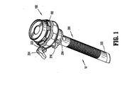
ここで、図面を参照して、図面では、同様の参照番号は、いくつかの図面全体で同一または実質的に類似のパーツを識別する。図1〜2は、カニューレアセンブリ200のようなアクセスデバイスに取り付けられたシールアセンブリ100を取り込む、本開示の入口システム10を示す。カニューレアセンブリ200は、体腔に入るという意図された目的のために適切な任意の入口部材であり得、そして代表的には、それを通る器具の導入を許容する通路を規定する。カニューレアセンブリ200は、腹腔が適切なガス、例えば、CO2でガス注入され、その中の内部器官から腹腔壁を持ち上げる腹腔鏡手術における使用のために特に適合されている。カニューレアセンブリ200は、代表的には、カニューレアセンブリ200の通路内に配置可能な、鈍いか、ブレードではないか、または鋭い先端の器具であり得る閉塞具アセンブリ(図示はされていない)とともに用いられ得る。この閉塞具アセンブリは、腹部壁を貫通するか、または腹部壁を通ってカニューレアセンブリ200を導入するために利用され、そして次に続いてカニューレアセンブリ200から除去され、この通路を通る手順を実施するために利用される外科用器具の導入を可能にする。
Referring now to the drawings, wherein like reference numerals identify identical or substantially similar parts throughout the several views. 1-2 illustrate an inlet system 10 of the present disclosure that incorporates a
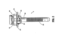
図3〜4に関し、図1〜2と組み合わせ、カニューレアセンブリ200は、カニューレスリーブ202、およびカニューレスリーブ202の近位端に取り付けられたカニューレハウジング204を含む。カニューレスリーブ202は、このカニューレスリーブ202の長さに沿って延びる長手方向軸「t」を規定し、そして近位(または先導)端206および遠位(または追従)端208を有する。カニューレスリーブ202の近位端206に隣接して取り付けられるのは、スリーブフランジ210である。カニューレスリーブ202はさらに、外科用器具の通過を許容するような寸法である内部長手方向通路212を規定する。カニューレスリーブ202は、ステンレス鋼またはポリカーボネートなどのようなポリマー材料を含むその他の剛性材料のような任意の適切な医療グレード材料から形成され得る。カニューレスリーブ202は、透明または不透明であり得る。カニューレスリーブ202の直径は変動し得るが、代表的には、約3.0〜約18mmの範囲である。カニューレスリーブ202は、組織内でカニューレスリーブ202の保持を容易にするための手段を含んでいてもよいし、または、含んでいなくてもよい。このような手段は、例えば、本出願人に譲渡された、2005年6月30日に出願されたSmithによる米国特許出願番号第11/170,824号に開示されるロック配列のような複数のロック要素またはリブを含み得、この’824号の全体の内容は、本明細書によって、本明細書中に援用される。
With reference to FIGS. 3-4, in conjunction with FIGS. 1-2,
カニューレハウジング204は、カニューレスリーブ202のスリーブフランジ210に、差し込みカップリング、ねじによる連結、スナップ係合、超音波溶接、または例えば、接着剤手段を含む当業者によって想定される任意のその他の手段を含む従来手段によって、連結され得る。カニューレアセンブリ200はまた、スリーブフランジ210とカニューレハウジング204との間に配置されたO−リングシール214を取り込み得、カニューレアセンブリ200の内部通路を密封する際に支援する。カニューレハウジング204は、単一の一体形成されたユニットであるか、または前述の連結手段のいずれかによって互いに連結された、いくつかの構成要素からなり得る。カニューレハウジング204はさらに、臨床医の指による把持係合のための寸法および配列である、直径方向の反対にあるハウジンググリップ216を含む。さらに、または、それに代わって、フィラメントの縫合糸アンカーが、カニューレハウジング210から、例えば、ハウジンググリップ216から、患者の表皮への取り付けのために延び得る。
The
図1〜5を参照して、カニューレハウジング204はさらに、バルブ218を含む。バルブ218は、上記外科用物体の不在の下で、および/または加圧された腔のガス注入法ガスに応答して閉じるように適合されているスリット220を有するダックビルバルブのようなゼロ閉鎖バルブであり得る。代替の例では、バルブ218は、ゲルシール、バルーンバルブ、またはフラッパーバルブであり得る。カニューレハウジング204はさらに、ストップコックバルブ224が取り付けられるポート222を含み得る。ポート222は、ストップコックバルブ224の開口部を経由してカニューレスリーブ202を通るガス注入法ガスの導入を許容し、気腹術の完全性を維持する際に支援する。ストップコックバルブ224は、任意の従来バルブであり得る。図5で最も良く描写されるように、カニューレハウジング204はさらに、少なくとも1つの、例えば、3つの周縁溝226を含む、溝226は軸方向に延び、そして好ましくは、カニューレハウジング204の周縁の周りにおいて等距離に間隔を置かれる。溝226は、シールアセンブリ100をカニューレアセンブリ200に離脱可能に取り付けることを支援する。
With reference to FIGS. 1-5,
ここで図5〜6を図3〜4と組み合わせて参照し、シールアセンブリ100が詳細に論議される。シールアセンブリ100は、一般に参照番号102として識別されるシールハウジング、このシールハウジング102内に配置されている複合物の物体シール104および内部ロック要素106を含む。シールハウジング102はこのアセンブリのシール構成要素を収容し、そしてシールアセンブリ100の外側バルブまたはシール本体を規定する。シールハウジング102は、好ましくはカニューレスリーブ102の軸「t」に平行であり、そしてより特定すれば、シールアセンブリ100がカニューレアセンブリ200に取り付けられるとき、カニューレスリーブ102の軸「t」と一致する中央シールハウジング軸「b」を規定する。シールハウジング102は、単一ユニットとして一体にまたはモノリシックな構造で形成され得るか、または一緒にアセンブルされるとき、シールハウジング102を形成する複数の構成要素を取り込み得る。示される実施形態では、シールハウジング102は、適切なポリマー材料から形成される単一ユニットである。適切なポリマー材料は、ポリカーボネート、ポリスチレン、ABSまたは当業者によって企図される任意のその他の材料を含む。
Referring now to FIGS. 5-6 in combination with FIGS. 3-4, the
シールハウジング102は、中央アパーチャ110、および端部壁108から垂れ、そしてシールハウジング軸「b」の周りに同軸で配列される内部環状カラー112を規定する近位の端部壁108を含む。中央アパーチャ110および環状カラー112は、外科用物体を受容し、そして比較的大きなサイズの器具の通過を許容するように適合された内部寸法または直径を集合的に規定する。環状カラー112はまた、外科用物体、例えば、外科用器具の、シール軸「b」に対する側方またはオフセットの移動の程度を、この器具の移動の外側限界を規定することにより制限し得る。シールハウジング102はさらに、論議されるように、物体シール104の構成要素を受容するために、シールハウジング102の長手方向の中点にほぼ隣接する内部周縁窪みまたはチャンネル114(図4)を規定する。
The
シールハウジング102はさらに、その遠位端に隣接する取り付けカラー116を含む。取り付けカラー116は、カニューレハウジング204に選択的に離脱可能に連結可能であり得、協働してシールアセンブリ100をカニューレアセンブリ200に離脱可能に連結する。取り付けカラーをカニューレハウジングに離脱可能に固定または連結するための種々の手段が想定され、差し込みカップリング、スナップ係合、摩擦係合、トルクおよび溝配列、ねじによる整列、カム−ロック機構などを含む。企図される1つの方法は、本明細書中以下でより詳細に論議される。あるいは、シールハウジング102は、カニューレハウジング204に永久的に固定され得る。取り付けカラー116は、不規則な外面を有し得、臨床医による係合を容易にする。1つの実施形態では、取り付けカラーは、間隔を置いた窪み118の配列を含み、シールアセンブリ100の把持を支援する。
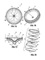
図4および6を考慮して図7A〜7Dを特に参照し、複合物の物体シール104が詳細に論議される。物体シール104は、近位方向から遠位方向に、保持部材120、第1の繊維セグメント122、エラストマーセグメント124、第2の繊維セグメント126、発泡体セグメント128および第3の繊維セグメント130を含む。保持部材120は、形状がほぼ環状またはリング様であり、そしてポリプロピレン、ナイロン、ABS、ポリカーボネート、ステンレス鋼、チタンまたは任意のその他の適切な材料のような適切な生体適合性の比較的剛な材料から製作され得る。保持部材120は、シールハウジング102の周縁チャネル114内への受け入れにより、シールハウジング102内への物体シール104の取り付けを支援する(図4)。第1の繊維セグメント122、第2の繊維セグメント126および第3の繊維セグメント130は、各々、ディスク形状の層の形態であり得る。繊維セグメント122、126、130は、一般に、発泡体セグメント128をカプセル化および支持するための支持枠または構造を提供することにより、物体シール104の構造的一体性を高める。繊維セグメント122、130はまた、物体シール104の発泡体セグメント128が、物体シール104を通る器具の挿入および恐らくは引き抜きの間にこの器具と接触することを防ぎ得る。繊維セグメント122、126、130はまた、シール耐久性を増大し、そして物体または器具挿入力を低減し得る。繊維セグメント122、126、130の各々のための適切な繊維材料は、South CarolinaのMillikenから市販され入手可能である、例えば、20%のLYCRATMを含むSPANDEXTM材料を含む。繊維は、ポリマー材料の織られた、編まれた、組紐にされた、または不織の材料を含み得る。その他の繊維材料がまた想定される。例えば、ナイロン(登録商標)、Kevlar(E.I.DuPont de Nemours and Companyの商標)のような合成材料、またはそれを通って挿入される器具の周りで拡大および圧縮する任意のその他の材料が想定される。さらに、上記繊維は、例えば、その内側が、ウレタン、シリコンまたはその他の可撓性潤滑性材料で被覆され得、上記シールを通る器具またはその他の物体の通過を容易にする。
With particular reference to FIGS. 7A-7D in view of FIGS. 4 and 6, the
各繊維セグメント122、126、130は、アパーチャ、開口部または通路を規定し得、外科用物体の通過を許容する。任意の1つ以上の繊維セグメント122、126、130内の単一または複数の交差するスリットがまた想定される。例えば、第2の繊維セグメント126は、シール軸「b」から外方に延びる少なくとも1つ、可能であれば、複数のスリット132を規定し得る。1つの実施形態では、スリット132は、実質的に直線状であり、そしてシール軸「b」に対して半径方向外側に延びる。その他の配列が想定され、非直線状のスリット、ヘビ状のスリット、交差するスリットを含む。スリット132は、シール軸の周りに等距離かつ半径方向に間隔を置かれ得る。スリット132は、物体の周りの繊維セグメント130の内部領域の半径方向狭窄を低減することにより、手術部位中に物体を進行するために必要な挿入および引き抜き力を低減する際に支援し得る。
Each
図7A〜7Dを続けて参照し、エラストマーセグメント124は、発泡体セグメント128の材料の弾性より小さい弾性を示し得る適切なエラストマーまたは熱可塑性ポリマーから製作される。エラストマーセグメント124は、挿入の間に、外科用物体、例えば、器具による刺し傷の可能性を最小にすることにより、発泡体セグメント128への保護を提供する。エラストマーセグメント128はポリイソプレンから製作され得る;しかし、その他のエラストマーがまた想定され、ネオプレン、シリコーン、ブチル、ニトリルおよびBuna−Nを含む。
With continued reference to FIGS. 7A-7D, the
発泡体セグメント128は、1つの実施形態では、発泡剤を含む熱可塑性材料のような発泡体材料(閉鎖セルまたは開放セル)から製作される。発泡体セグメント128は、外科用物体の周りの主要な密封構成要素であり得る。1つの実施形態では、発泡体セグメント128は、例えば、CELOGENTM、EXPANDEXTM、およびOPEXTM化学的発泡剤を含む発泡剤が含浸または注入されたポリイソプレンから製作される。発泡体セグメント128は、挿入された器具の周りで曲がり、そして変形するのに十分な弾性を有し、その一方で、物体、例えば、器具の外側寸法の周囲で一致し、それによって、この物体の周囲に気密性のシールを確立する。発泡体セグメント128は、器具の軸方向運動を吸収することに十分に対応可能である。さらに、発泡体セグメント128のこの対応可能な特徴は、上記器具のずれ(オフセット)操作の間における、この器具の周りでのギャップの形成を実質的に最小にし得る。ギャップの存在は、そうでなければ、下にある気腹からのガスの所望されない放出を許容し得る。
The
物体シール104のアセンブルされた状態では、図7Cで最も良く描写されるように、この物体シール104は、ほぼテーパー状または漏斗状のプロフィールを規定し、それによって、物体シール104の内部領域は、シール軸「b」に対して斜めの角度で傾く。この漏斗状の特徴は、器具の初期導入の間に中央アパーチャ134に向かって器具を案内することを支援し得る。この漏斗状の特徴はまた、器具の引き抜きの間に物体シール104の反転の可能性を実質的に最小にする。より詳細には、物体シール104は、繊維セグメント122に隣接する近位シール面104pおよび弓状、放物線状または双曲線状プロフィールを規定する繊維セグメント130に隣接する遠位シール面104dを規定する。1つの実施形態では、近位シール面104pは、約0.540インチから約0.620インチの範囲の曲率半径「m」を有する表面部分を規定し得、そして遠位シール面104dは、約0.430インチから約0.500インチの範囲の曲率半径「K」を有する表面部分を規定し得る。その他の寸法、および曲率半径がまた想定される。物体シール104の軸方向長さ「j」は、(保持部材120を除いて)約0.47インチ〜約0.53インチの範囲である。傾斜した配列により行われる全体の寸法は、物体シール104に、際だった漏斗状プロフィールを提供し、これは、物体シール104を通る外科用物体の方向付けまたは送り込みを容易にし、そしてまた、この物体の引き抜きの間の物体シール104の反転の可能性を最小にする。
In the assembled state of the
物体シール104は、従来手段を介して製造され得る。1つの実施形態では、繊維セグメント122、126、130、エラストマーセグメント124および発泡体セグメント128は圧縮成形され得、その一方、エラストマーセグメント124のエラストマー材料および/または発泡体セグメント128の発泡体材料は、これらエラストマーセグメント124および/または発泡体セグメント128中に繊維セグメント122、126、130の繊維材料を少なくとも部分的に埋め込むために加熱される。あるいは、物体シール104の構成要素は、接着剤、セメントなどで取り付けられ得る。繊維セグメント122、126、130を、エラストマーセグメント124および発泡体セグメント128の1つ、または両方に付着するための方法が、Racenetによる米国特許第6,702,787号の特定の実施形態に開示されるように、また利用され得る。Racenetによる米国特許第6,702,787号の全体の開示は、本明細書中に参考として本明細書によって援用される。シール104を製作するための別の方法は、(H−US−00875)中に開示され、その全体の内容は、本明細書中に参考として援用される。一旦、物体シール104がアセンブルまたは製造されると、中央シールアパーチャ134が、ダイパンチを用いてこの複合体材料を貫通して穿孔され得るか、またはシールアパーチャ134を提供する成形プロセスを介して作製され得る。あるいは、物体シール104の個々の構成要素は、協働するアパーチャまたはスリットとともに提供され得、そして次に前述の方法のいずれかを介してアセンブルされる。
The
代替例では、物体シール104は、アパーチャ、スリットなどを有する実質的に平坦または平面状の隔壁シールであり得る。物体シール104はまた、発泡体セグメント128に加え、またはそれに代わって、ゲル組成物または非常に柔軟な熱可塑性エラストマーを含み得る。使用のために企図されるゲルおよび柔軟な熱可塑性材料は、商標名VERSAFLEXTM、FLEXPLASTTM、DYANFLEXTMおよびMONPRENETMの下で公知である。その他の適切な材料は、ソフトシリコーンとポリウレタンとの複合体を含む。これら材料は、十分に成形しやすいように適合され得る。
In the alternative, the
物体シール104は、潤滑剤または治療もしくは薬理学的薬剤を取り込み得る。適切な潤滑剤は、プラズマ重合プロセスによって調製されるヒドロシクロシロキサンの被覆を含む。このような被覆は、Huらによる米国特許番号第5,463,010号に開示され、その全体の内容は、参考として本明細書によって援用される。治療もしくは薬理学的薬剤の例は、抗微生物剤、抗細菌剤、止血剤、生理食塩水のような湿度提供剤、治癒剤、潤滑剤、鎮痛剤、成長因子、および/または抗炎症剤を含む。
ここで、図8A〜8Cを図4および6と組み合わせて参照し、シールアセンブリ100のロックリング106が論議される。ロックリング106は、シールハウジング102内に物体シール104を固定すること、およびアセンブルされたシールアセンブリ100およびカニューレアセンブリ200の通路内に内部シールを提供することの二重の機能を供する。ロックリング106は、本明細書で上記に記載された任意のエラストマー材料を含む特定の弾性を示す材料から製作され得る。ロックリング106は、外側セグメント136および内部ガスケットセグメント138を含む。外側セグメント136は、周縁の周りで等距離間隔を置かれた複数(例えば3)の周縁の窪み140を規定する。窪み140は、シールハウジング102内にロック部材106を取り付けることを支援する。ロックリング106の内部ガスケットセグメント138は、シールアセンブリ100のアセンブルされた状態で物体シール104の遠位シール面104dと接触し得る。外側セグメント136および内部ガスケットセグメント138は、一体形成され得るか、または従来手段により互いに受容される別個の構成要素からなり得る。内部ガスケットセグメント138は、外側セグメント136より弾性であり得る。外側セグメント136は、外側セグメントの環状の窪みの中に第1および第2のO−リングシール142を取り込み得、シールハウジング102の内部開口部をシールすることを支援する。
Referring now to FIGS. 8A-8C in combination with FIGS. 4 and 6, the
シールアセンブリ100のアセンブルがここで論議される。図4と組み合わせて、図9A〜9Fを参照し、物体シール104は、シールハウジング102の内部領域と整列させられ、そしてシールハウジング102の中を進行させられ、それによって、保持部材120がシールハウジング102のチャンネル144内に受容される(図4をまた参照のこと)。ロックリング106がその後に配置され、それによってロックリング106の周縁窪み140が、シールハウジング102の内壁から半径方向内側に延びる取り付けタブ142と整列させられる。特に、図9D〜9Eで最も良く描写されるように、取り付けタブ142は、シールハウジング102の内部に配置される。少なくとも2つ、例えば、3つの取り付けタブ142、およびロックリング106の付随する周縁窪み140が想定される。ロックリング106はシールハウジング102の中を進行させられ、取り付けタブ142はロックリング106の周縁窪み140内に受容される。その後、ロックリング106は、シールハウジング102に対して回転させられ、シールハウジング102の取り付けタブ142がロックリング106の裏面上の周縁面に沿って載り、個々の周縁窪み140との整列から抜け出る。この配列では、図9Eに描写されるように、取り付けタブ140は、ロックリング106の裏面に対して固定される。取り付けタブ140は、最初、ロックリング106および隣接する窪み140の裏面上に提供される傾斜またはカム作用面144に沿って載り得、物体シール104に対してロックリング106を引くことが想定される。ロックリング106の裏面は、その中に形成されたロック窪み146を有し得、シールハウジング102に対してロックタブ106を固定することを支援することがさらに想定される。図9Dは、アセンブルされたシールアセンブリ100を示す。
The assembly of the
シールアセンブリ100は、種々の態様で、カニューレアセンブリ200と連結または接続され得る。好ましい実施形態では、シールアセンブリ100のシールハウジング102、およびカニューレアセンブリ200のカニューレハウジング204は、互いに、例えば、差し込みロック、ねじによる取り付け、ラッチ取り付けなどの機械的手段により、互いに離脱可能に係合するように適合される。1つの好ましい実施形態では、シールハウジング102は、図9D〜9Eで最も良く描写されるように、少なくとも2つ、好ましくは3つのハウジングロック移動止め148を含む。ロック移動止め148は、シールアセンブリ100のカニューレアセンブリ200への取り付けの間に、カニューレハウジング204の軸方向窪み(図5)と整列させられ、そしてそれに続いて受容される。1つの実施形態では、シールハウジング102およびカニューレハウジング204は、互いに対して回転させられ、下にあるハウジングロック移動止めをカニューレハウジング204内に規定される環状棚228の上に配置し、上記構成要素を受容する。あるいは、シールハウジング102およびカニューレハウジング204は、摩擦係合などを介して互いに離脱可能に固定され得る。シールアンンブリは、手術部位内でカニューレアセンブリ200への付与の前、付与の間、または付与の後に、カニューレアセンブリ200に取り付けられ得る。
図10は、腹腔鏡手順の間の外科的処置の実施と組み合わせて、シールアセンブリ100およびカニューレアセンブリ200の使用を示すフローチャート500を示す。腹腔はガス注入されて気腹術を確立する(ステップ502)。シールアセンブリ100は、本明細書において上記で論議されたように、カニューレアセンブリ200に取り付けられる(ステップ504)。アセンブルされた入口システム10は、代表的には、鋭いか、またはブレードでないトロカール閉塞具を利用してガス注入された腹腔中に導入され、腹腔にアクセスし(ステップ506)、そして閉塞具が除去される。器具は、物体シール104を通ってこの器具をシールアセンブリ100中に挿入することによって、入口システム10を通って進行され得(ステップ508)、それによって、物体シール104のアパーチャ134を規定する部分は伸張し、この器具をそれとの実質的に密封された関係で収容する。この器具は、遠位方向に、バルブ218を通り、そして体腔中を通過する。所望の外科的処置が、この器具によって実施される(510)。この器具の操作の間、少なくとも発泡体セグメント128の発泡体材料は、この器具の周囲に一致し、この器具の対向する側面上のあらゆるギャップの形成を防ぐ。繊維セグメント122、126、130、およびエラストマーセグメント124は、外科用器具の挿入、操作および引き抜きの間に発泡体セグメント128の一体性を維持すること、および保存することを支援する。
FIG. 10 shows a
形態および詳細における種々の改変および変更が、本発明の思想および範囲から逸脱することなく、本開示の実施形態になされ得ることが理解される。従って、上記の記載は、本発明を制限すると解釈されるべきではなく、その好ましい実施形態の単なる例示である。当業者は、本明細書に添付された請求項によって規定される本発明の範囲および思想内でその他の改変を想定する。このように、本発明を、特許法によって要求される上記詳細および特徴とともに説明したので、請求され、そして所望されて保護されるものは添付の請求項に呈示されている。 It will be understood that various modifications and changes in form and detail may be made to the embodiments of the present disclosure without departing from the spirit and scope of the invention. Therefore, the above description should not be construed as limiting the invention, but is merely exemplary of preferred embodiments thereof. Those skilled in the art will envision other modifications within the scope and spirit of the invention as defined by the claims appended hereto. Thus, since the present invention has been described with the above details and features required by patent law, what is claimed and desired protected is set forth in the appended claims.
100 シールアセンブリ
102 シールハウジング
200 カニューレアセンブリ
202 カニューレスリーブ
204 カニューレハウジング
222 ポート
100
Claims (15)
下にある組織へのアクセスを提供するように適合され、該入口部材の長手方向軸に沿って延びる長手方向開口部を有する入口部材であって、近位端および遠位端を規定する入口部材;および
外科用物体によって実質的に密封される関係にある、該外科用物体の受容および通過のための通路を有する内面を含み、そしてシール軸を規定するシールであって、発泡体材料を含む発泡体セグメント、および繊維材料を含み該発泡体セグメントに対して取り付けられる繊維セグメントを含むシールを備える、外科用入口アセンブリ。 A surgical portal assembly comprising:
An inlet member adapted to provide access to underlying tissue and having a longitudinal opening extending along a longitudinal axis of the inlet member, the inlet member defining a proximal end and a distal end A seal that includes an inner surface having a passage for receiving and passing the surgical object in a substantially sealed relationship with the surgical object and defining a seal axis, the foam comprising a foam material A surgical portal assembly comprising a foam segment and a seal including a fibrous segment that includes a fibrous material and is attached to the foam segment.
Applications Claiming Priority (1)
| Application Number | Priority Date | Filing Date | Title |
|---|---|---|---|
| US99784507P | 2007-10-05 | 2007-10-05 |
Publications (1)
| Publication Number | Publication Date |
|---|---|
| JP2009090111A true JP2009090111A (en) | 2009-04-30 |
Family
ID=40279848
Family Applications (1)
| Application Number | Title | Priority Date | Filing Date |
|---|---|---|---|
| JP2008259101A Pending JP2009090111A (en) | 2007-10-05 | 2008-10-03 | Surgical portal with foam and fabric composite seal assembly |
Country Status (6)
| Country | Link |
|---|---|
| US (1) | US20090093682A1 (en) |
| EP (1) | EP2044898A1 (en) |
| JP (1) | JP2009090111A (en) |
| CN (1) | CN101401733A (en) |
| AU (1) | AU2008229801A1 (en) |
| CA (1) | CA2640349A1 (en) |
Cited By (2)
| Publication number | Priority date | Publication date | Assignee | Title |
|---|---|---|---|---|
| JP2016179182A (en) * | 2009-12-23 | 2016-10-13 | アルコン リサーチ, リミテッド | Ophthalmic valved trocar cannula |
| JP2018061612A (en) * | 2016-10-11 | 2018-04-19 | 京セラオプテック株式会社 | Seal unit for trocar |
Families Citing this family (34)
| Publication number | Priority date | Publication date | Assignee | Title |
|---|---|---|---|---|
| CA2522766C (en) * | 2003-04-25 | 2011-07-05 | Tyco Healthcare Group Lp | Surgical hand access apparatus |
| US20100228096A1 (en) * | 2009-03-06 | 2010-09-09 | Ethicon Endo-Surgery, Inc. | Methods and devices for providing access into a body cavity |
| US8915842B2 (en) | 2008-07-14 | 2014-12-23 | Ethicon Endo-Surgery, Inc. | Methods and devices for maintaining visibility and providing irrigation and/or suction during surgical procedures |
| US8690831B2 (en) | 2008-04-25 | 2014-04-08 | Ethicon Endo-Surgery, Inc. | Gas jet fluid removal in a trocar |
| US8579807B2 (en) | 2008-04-28 | 2013-11-12 | Ethicon Endo-Surgery, Inc. | Absorbing fluids in a surgical access device |
| US8636686B2 (en) | 2008-04-28 | 2014-01-28 | Ethicon Endo-Surgery, Inc. | Surgical access device |
| US8870747B2 (en) * | 2008-04-28 | 2014-10-28 | Ethicon Endo-Surgery, Inc. | Scraping fluid removal in a surgical access device |
| US8568362B2 (en) | 2008-04-28 | 2013-10-29 | Ethicon Endo-Surgery, Inc. | Surgical access device with sorbents |
| USD700326S1 (en) | 2008-04-28 | 2014-02-25 | Ethicon Endo-Surgery, Inc. | Trocar housing |
| US8273060B2 (en) | 2008-04-28 | 2012-09-25 | Ethicon Endo-Surgery, Inc. | Fluid removal in a surgical access device |
| US11235111B2 (en) | 2008-04-28 | 2022-02-01 | Ethicon Llc | Surgical access device |
| US9358041B2 (en) | 2008-04-28 | 2016-06-07 | Ethicon Endo-Surgery, Llc | Wicking fluid management in a surgical access device |
| US7981092B2 (en) | 2008-05-08 | 2011-07-19 | Ethicon Endo-Surgery, Inc. | Vibratory trocar |
| US9737334B2 (en) | 2009-03-06 | 2017-08-22 | Ethicon Llc | Methods and devices for accessing a body cavity |
| US8449459B2 (en) * | 2009-03-31 | 2013-05-28 | Covidien Lp | Access portal including silicone foam three layer seal |
| US8353825B2 (en) * | 2009-04-02 | 2013-01-15 | Covidien Lp | Access portal including sponge |
| US20100261972A1 (en) * | 2009-04-08 | 2010-10-14 | Ethicon Endo-Surgery, Inc. | Surgical Access Device with One Time Seal |
| US20110082340A1 (en) * | 2009-10-07 | 2011-04-07 | Tyco Healthercare Group LP | Foam collar for surgical access devices |
| US20110196205A1 (en) * | 2010-02-05 | 2011-08-11 | Tyco Healthcare Group Lp | Surgical portal locking system |
| ITRM20100207A1 (en) * | 2010-05-03 | 2011-11-04 | Ab Medica Spa | HOLDING DEVICE FOR TROCAR AND RELATED TROCAR. |
| US20120130178A1 (en) * | 2010-11-23 | 2012-05-24 | Tyco Healthcare Group Lp | Access apparatus including desufflation control mechanism |
| FR2969128B1 (en) * | 2010-12-21 | 2012-12-28 | Bio Rad Pasteur | CAP FOR CLOSING A CONTAINER |
| US9393042B2 (en) * | 2011-06-01 | 2016-07-19 | Applied Medical Resources Corporation | Coaxial trocar seals havng sequential adjacent openings |
| US8870749B2 (en) * | 2011-09-02 | 2014-10-28 | Stryker Corporation | Arrangement for minimal access surgery |
| KR101303004B1 (en) * | 2012-02-29 | 2013-09-10 | 가톨릭대학교 산학협력단 | Inspection auxiliary tool for colonoscopy |
| EP2846713A1 (en) | 2012-05-09 | 2015-03-18 | EON Surgical Ltd. | Laparoscopic port |
| WO2014116889A1 (en) * | 2013-01-24 | 2014-07-31 | Covidien Lp | Surgical seal assembly including an overlapping guard structure for a seal |
| US10172640B2 (en) * | 2015-04-17 | 2019-01-08 | Life Care Medical Devices, Ltd. | Device for lifting abdominal wall during medical procedure |
| US20150031958A1 (en) * | 2013-07-25 | 2015-01-29 | Covidien Lp | Surgical seal assembly with upper lip seal |
| US10543018B2 (en) * | 2015-05-15 | 2020-01-28 | Covidien Lp | Surgical access device |
| EP3389756B1 (en) * | 2015-12-18 | 2023-11-22 | Boston Scientific Scimed Inc. | Vascular introducer hubs for reducing blood leakage |
| US10327809B2 (en) | 2016-02-29 | 2019-06-25 | Covidien Lp | Clip collar advanced fixation |
| EP3515380B1 (en) | 2016-09-21 | 2023-06-07 | Coloplast A/S | Ostomy device |
| US20190059938A1 (en) * | 2017-08-28 | 2019-02-28 | Covidien Lp | Access apparatus including seal component with protective guards |
Family Cites Families (85)
| Publication number | Priority date | Publication date | Assignee | Title |
|---|---|---|---|---|
| US578676A (en) * | 1897-03-09 | Mechanism for grinding car-wheels | ||
| US3402710A (en) * | 1966-06-27 | 1968-09-24 | Hydra Power Corp | Self-closing valve device for implantation in the human body |
| US4447237A (en) * | 1982-05-07 | 1984-05-08 | Dow Corning Corporation | Valving slit construction and cooperating assembly for penetrating the same |
| US4475548A (en) * | 1982-06-01 | 1984-10-09 | Rudolph Muto | Fitting for endotracheal tube apparatus and method of making the fitting |
| US4610665A (en) * | 1983-01-18 | 1986-09-09 | Terumo Kabushiki Kaisha | Medical instrument |
| US4519908A (en) * | 1984-03-12 | 1985-05-28 | Woodruff Seth D | Valve for control of fluid flow |
| US5015228A (en) * | 1989-06-05 | 1991-05-14 | Eastman Kodak Company | Sterilizing dressing device and method for skin puncture |
| US5127626A (en) * | 1989-10-31 | 1992-07-07 | Applied Vascular Devices, Inc. | Apparatus for sealing around members extending therethrough |
| US5330497A (en) * | 1989-11-22 | 1994-07-19 | Dexide, Inc. | Locking trocar sleeve |
| US5041095A (en) * | 1989-12-22 | 1991-08-20 | Cordis Corporation | Hemostasis valve |
| US5207656A (en) * | 1990-04-19 | 1993-05-04 | Cordis Corporation | Medical instrument valve having foam partition member |
| US5484425A (en) * | 1990-05-01 | 1996-01-16 | Cathco, Inc. | Radiopaque non-kinking thin-walled introducer sheath |
| US5180376A (en) * | 1990-05-01 | 1993-01-19 | Cathco, Inc. | Non-buckling thin-walled sheath for the percutaneous insertion of intraluminal catheters |
| US5429609A (en) * | 1990-07-26 | 1995-07-04 | Yoon; Inbae | Endoscopic portal for use in endoscopic procedures and methods therefor |
| US5389080A (en) * | 1990-07-26 | 1995-02-14 | Yoon; Inbae | Endoscopic portal for use in endoscopic procedures and methods therefor |
| US5104389A (en) * | 1991-06-27 | 1992-04-14 | Cordis Corporation | Medical instrument valve with foam partition member having vapor permeable skin |
| US6569120B1 (en) * | 1991-10-18 | 2003-05-27 | United States Surgical Corporation | Seal assembly |
| US6981966B2 (en) * | 1991-10-18 | 2006-01-03 | United States Surgical | Valve assembly for introducing instruments into body cavities |
| US20050096605A1 (en) * | 1992-04-24 | 2005-05-05 | Green David T. | Valve assembly for introducing instruments into body cavities |
| CA2093748C (en) * | 1992-04-24 | 1996-11-12 | Roy D. Gravener | Valve assembly for introducing instruments into body cavities |
| US5743884A (en) * | 1992-12-17 | 1998-04-28 | Hasson; Harrith M. | Sealing structure for medical instrument |
| US5338313A (en) * | 1992-12-17 | 1994-08-16 | Thomas J. Fogarty, M.D. | Adjustable valve having a radially compressible sealing body |
| US5407433A (en) * | 1993-02-10 | 1995-04-18 | Origin Medsystems, Inc. | Gas-tight seal accommodating surgical instruments with a wide range of diameters |
| JPH06309485A (en) * | 1993-02-25 | 1994-11-04 | Nippondenso Co Ltd | Optical information reader |
| US5391153A (en) * | 1993-04-09 | 1995-02-21 | Habley Medical Technology Corporation | Trocar with linear movement seal |
| US5342315A (en) * | 1993-04-12 | 1994-08-30 | Ethicon, Inc. | Trocar seal/protector assemblies |
| US5389081A (en) * | 1993-05-18 | 1995-02-14 | United States Surgical Corporation | Stabilizer for a valve assembly for introducing instruments into body cavities |
| US5463010A (en) | 1993-11-12 | 1995-10-31 | Surface Engineering Technologies, Division Of Innerdyne, Inc. | Hydrocyclosiloxane membrane prepared by plasma polymerization process |
| DE4401237C2 (en) * | 1994-01-18 | 1997-06-05 | Ruesch Willy Ag | Trocar device |
| US5407434A (en) * | 1994-01-27 | 1995-04-18 | The Kendall Company | Automatic lumen viscous reseal |
| US5480410A (en) * | 1994-03-14 | 1996-01-02 | Advanced Surgical, Inc. | Extracorporeal pneumoperitoneum access bubble |
| US5460616A (en) * | 1994-04-19 | 1995-10-24 | Cordis Corporation | Catheter introducer with fluid chamber valve |
| US5603702A (en) * | 1994-08-08 | 1997-02-18 | United States Surgical Corporation | Valve system for cannula assembly |
| US5514133A (en) * | 1994-08-26 | 1996-05-07 | Golub; Robert | Access device for endoscopic surgery |
| US5672168A (en) * | 1994-10-07 | 1997-09-30 | De La Torre; Roger A. | Laparoscopic access port for surgical instruments or the hand |
| US5653705A (en) * | 1994-10-07 | 1997-08-05 | General Surgical Innovations, Inc. | Laparoscopic access port for surgical instruments or the hand |
| US5599305A (en) * | 1994-10-24 | 1997-02-04 | Cardiovascular Concepts, Inc. | Large-diameter introducer sheath having hemostasis valve and removable steering mechanism |
| US5697914A (en) * | 1995-03-16 | 1997-12-16 | Becton Dickinson And Company | Control forward/flashback forward one hand introducer needle and catheter assembly |
| US5741298A (en) * | 1995-04-28 | 1998-04-21 | Macleod; Cathel | Method and devices for video-assisted surgical techniques |
| US5634937A (en) * | 1995-05-19 | 1997-06-03 | General Surgical Innovations, Inc. | Skin seal with inflatable membrane |
| US5662615A (en) * | 1995-09-01 | 1997-09-02 | Blake, Iii; Joseph W. | Valve and valve cartridge for trocar |
| US5628732A (en) * | 1996-01-19 | 1997-05-13 | Ethicon Endo-Surgery, Inc. | Trocar with improved universal seal |
| US5814026A (en) * | 1996-03-19 | 1998-09-29 | Yoon; Inbae | Endoscopic portal having a universal seal and methods for introducing instruments therethrough |
| AU3132097A (en) * | 1996-05-20 | 1997-12-09 | Percusurge, Inc. | Low profile catheter valve |
| US5738664A (en) * | 1996-09-30 | 1998-04-14 | Becton Dickinson And Company | Self-healing seal for use in medical devices |
| JP2957134B2 (en) * | 1996-10-08 | 1999-10-04 | 株式会社八光電機製作所 | Valve and valved trocar mantle |
| US6245048B1 (en) * | 1996-12-16 | 2001-06-12 | Icu Medical, Inc. | Medical valve with positive flow characteristics |
| US6079692A (en) * | 1997-04-03 | 2000-06-27 | Hunter Innovations | Combination diaphragm and groove coupler seal for automatic control valves |
| US5906577A (en) * | 1997-04-30 | 1999-05-25 | University Of Massachusetts | Device, surgical access port, and method of retracting an incision into an opening and providing a channel through the incision |
| US6440063B1 (en) * | 1997-04-30 | 2002-08-27 | University Of Massachusetts | Surgical access port and laparoscopic surgical method |
| JP4647727B2 (en) * | 1997-05-02 | 2011-03-09 | ユナイテッド ステイツ サージカル コーポレイション | Trocar sealing device |
| US5779697A (en) * | 1997-05-28 | 1998-07-14 | Linvatec Corporation | Arthroscopic cannula with fluid seals |
| AU7279898A (en) * | 1997-05-28 | 1998-12-30 | United States Surgical Corporation | Trocar seal system |
| US6017356A (en) * | 1997-09-19 | 2000-01-25 | Ethicon Endo-Surgery Inc. | Method for using a trocar for penetration and skin incision |
| US6860869B2 (en) * | 1999-03-26 | 2005-03-01 | William G. Dennis | Surgical instrument seal assembly |
| US7101353B2 (en) * | 1999-12-30 | 2006-09-05 | Cook Vascular Incorporated | Splittable medical valve |
| CA2395338C (en) * | 1999-12-30 | 2009-02-10 | Cook Vascular Incorporated | Splittable medical valve |
| US6551283B1 (en) * | 2000-01-25 | 2003-04-22 | St. Jude Medical, Daig Division | Hemostasis valve |
| US7153319B1 (en) * | 2000-01-26 | 2006-12-26 | Genico, Inc. | Trocar system having shielded trocar |
| US6602240B2 (en) * | 2000-02-15 | 2003-08-05 | Thomas J. Fogarty | Method and device for maintaining a seal |
| US6663598B1 (en) * | 2000-05-17 | 2003-12-16 | Scimed Life Systems, Inc. | Fluid seal for endoscope |
| EP1326524B1 (en) * | 2000-10-19 | 2010-09-01 | Applied Medical Resources Corporation | Surgical access apparatus and method |
| US6896692B2 (en) * | 2000-12-14 | 2005-05-24 | Ensure Medical, Inc. | Plug with collet and apparatus and method for delivering such plugs |
| US6610031B1 (en) * | 2001-04-18 | 2003-08-26 | Origin Medsystems, Inc. | Valve assembly |
| US7344519B2 (en) * | 2001-08-31 | 2008-03-18 | Conmed Corporation | Trocar system |
| US7052454B2 (en) * | 2001-10-20 | 2006-05-30 | Applied Medical Resources Corporation | Sealed surgical access device |
| US7235062B2 (en) * | 2002-01-24 | 2007-06-26 | Applied Medical Resources Corporation | Surgical access device with floating gel seal |
| US7632250B2 (en) * | 2002-05-10 | 2009-12-15 | Tyco Healthcare Group Lp | Introducer seal assembly |
| US20040066008A1 (en) * | 2002-10-04 | 2004-04-08 | Smith Robert C. | Introducer seal assembly |
| US7105009B2 (en) * | 2002-10-16 | 2006-09-12 | Applied Medical Resources Corporation | Access device maintenance apparatus and method |
| US7390317B2 (en) * | 2002-12-02 | 2008-06-24 | Applied Medical Resources Corporation | Universal access seal |
| US20050020884A1 (en) * | 2003-02-25 | 2005-01-27 | Hart Charles C. | Surgical access system |
| CA2522766C (en) * | 2003-04-25 | 2011-07-05 | Tyco Healthcare Group Lp | Surgical hand access apparatus |
| AU2004234014C1 (en) * | 2003-04-25 | 2010-09-16 | Covidien Lp | Surgical access apparatus |
| US20050148823A1 (en) * | 2003-10-15 | 2005-07-07 | Trevor Vaugh | Surgical sealing device |
| US20050096695A1 (en) * | 2003-11-03 | 2005-05-05 | Olich Jack M. | Flexible foam seal assembly |
| US20060047293A1 (en) * | 2004-01-23 | 2006-03-02 | Haberland Gary W | Trocar having planar fixed septum seal and related methods |
| US20050165433A1 (en) * | 2004-01-23 | 2005-07-28 | Haberland Gary W. | Trocar having planar fixed septum seal and related methods |
| JP2008504051A (en) * | 2004-04-05 | 2008-02-14 | タイコ ヘルスケア グループ リミテッド パートナーシップ | Surgical hand access device |
| CA2574276C (en) * | 2004-07-21 | 2013-03-19 | Tyco Healthcare Group, Lp | Introducer assembly with suspended seal |
| US8241251B2 (en) * | 2004-08-25 | 2012-08-14 | Tyco Healthcare Group Lp | Gel seal for a surgical trocar apparatus |
| US20060129165A1 (en) * | 2004-11-24 | 2006-06-15 | Edrich Health Technologies, Inc. | Gel based laparoscopic trocar |
| US7481795B2 (en) * | 2004-12-17 | 2009-01-27 | Ethicon Endo-Surgery, Inc. | Circumferential trocar seal assembly |
| AU2006304141B2 (en) * | 2005-10-14 | 2012-07-05 | Applied Medical Resources Corporation | Gel cap for wound retractor |
| US20080011307A1 (en) * | 2006-07-12 | 2008-01-17 | Beckman Andrew T | Hand assisted laparoscopic device |
-
2008
- 2008-10-02 US US12/244,138 patent/US20090093682A1/en not_active Abandoned
- 2008-10-03 EP EP08253234A patent/EP2044898A1/en not_active Withdrawn
- 2008-10-03 JP JP2008259101A patent/JP2009090111A/en active Pending
- 2008-10-03 AU AU2008229801A patent/AU2008229801A1/en not_active Abandoned
- 2008-10-03 CA CA002640349A patent/CA2640349A1/en not_active Abandoned
- 2008-10-06 CN CNA2008101785210A patent/CN101401733A/en active Pending
Cited By (2)
| Publication number | Priority date | Publication date | Assignee | Title |
|---|---|---|---|---|
| JP2016179182A (en) * | 2009-12-23 | 2016-10-13 | アルコン リサーチ, リミテッド | Ophthalmic valved trocar cannula |
| JP2018061612A (en) * | 2016-10-11 | 2018-04-19 | 京セラオプテック株式会社 | Seal unit for trocar |
Also Published As
| Publication number | Publication date |
|---|---|
| US20090093682A1 (en) | 2009-04-09 |
| CN101401733A (en) | 2009-04-08 |
| EP2044898A1 (en) | 2009-04-08 |
| AU2008229801A1 (en) | 2009-05-07 |
| CA2640349A1 (en) | 2009-04-05 |
Similar Documents
| Publication | Publication Date | Title |
|---|---|---|
| JP2009090111A (en) | Surgical portal with foam and fabric composite seal assembly | |
| US9022986B2 (en) | Surgical portal with gel and fabric seal assembly | |
| US8177755B2 (en) | Access sheath with central seal | |
| EP1679043B1 (en) | Surgical seal for use in a surgical access apparatus | |
| EP1997446B1 (en) | Access apparatus with shallow zero closure valve | |
| EP2238928B1 (en) | Access portal including sponge | |
| US8241251B2 (en) | Gel seal for a surgical trocar apparatus | |
| US9119664B2 (en) | Integral foam port | |
| US20090093683A1 (en) | Surgical portal kit for use in single incision surgery | |
| JP2011125721A (en) | Surgical portal with rotating seal | |
| JP5607778B2 (en) | Surgical seal assembly | |
| JP2011200648A (en) | Portal apparatus with tubular seal device |
Legal Events
| Date | Code | Title | Description |
|---|---|---|---|
| A621 | Written request for application examination |
Free format text: JAPANESE INTERMEDIATE CODE: A621 Effective date: 20110802 |
|
| A072 | Dismissal of procedure [no reply to invitation to correct request for examination] |
Free format text: JAPANESE INTERMEDIATE CODE: A073 Effective date: 20121129 |