JP2009089158A - Imaging apparatus - Google Patents
Imaging apparatus Download PDFInfo
- Publication number
- JP2009089158A JP2009089158A JP2007257819A JP2007257819A JP2009089158A JP 2009089158 A JP2009089158 A JP 2009089158A JP 2007257819 A JP2007257819 A JP 2007257819A JP 2007257819 A JP2007257819 A JP 2007257819A JP 2009089158 A JP2009089158 A JP 2009089158A
- Authority
- JP
- Japan
- Prior art keywords
- visible light
- region
- video signal
- infrared light
- light region
- Prior art date
- Legal status (The legal status is an assumption and is not a legal conclusion. Google has not performed a legal analysis and makes no representation as to the accuracy of the status listed.)
- Pending
Links
- 238000003384 imaging method Methods 0.000 title claims abstract description 80
- 238000000034 method Methods 0.000 claims abstract description 18
- 238000010586 diagram Methods 0.000 description 9
- 230000010365 information processing Effects 0.000 description 2
- 230000035945 sensitivity Effects 0.000 description 2
- 230000000295 complement effect Effects 0.000 description 1
- 230000000694 effects Effects 0.000 description 1
- 229910044991 metal oxide Inorganic materials 0.000 description 1
- 150000004706 metal oxides Chemical class 0.000 description 1
- 230000003287 optical effect Effects 0.000 description 1
- 239000004065 semiconductor Substances 0.000 description 1
- 238000002834 transmittance Methods 0.000 description 1
Images


Classifications
-
- H—ELECTRICITY
- H04—ELECTRIC COMMUNICATION TECHNIQUE
- H04N—PICTORIAL COMMUNICATION, e.g. TELEVISION
- H04N23/00—Cameras or camera modules comprising electronic image sensors; Control thereof
- H04N23/10—Cameras or camera modules comprising electronic image sensors; Control thereof for generating image signals from different wavelengths
- H04N23/11—Cameras or camera modules comprising electronic image sensors; Control thereof for generating image signals from different wavelengths for generating image signals from visible and infrared light wavelengths
-
- H—ELECTRICITY
- H04—ELECTRIC COMMUNICATION TECHNIQUE
- H04N—PICTORIAL COMMUNICATION, e.g. TELEVISION
- H04N25/00—Circuitry of solid-state image sensors [SSIS]; Control thereof
- H04N25/10—Circuitry of solid-state image sensors [SSIS]; Control thereof for transforming different wavelengths into image signals
- H04N25/11—Arrangement of colour filter arrays [CFA]; Filter mosaics
- H04N25/13—Arrangement of colour filter arrays [CFA]; Filter mosaics characterised by the spectral characteristics of the filter elements
- H04N25/131—Arrangement of colour filter arrays [CFA]; Filter mosaics characterised by the spectral characteristics of the filter elements including elements passing infrared wavelengths
-
- H—ELECTRICITY
- H04—ELECTRIC COMMUNICATION TECHNIQUE
- H04N—PICTORIAL COMMUNICATION, e.g. TELEVISION
- H04N25/00—Circuitry of solid-state image sensors [SSIS]; Control thereof
- H04N25/10—Circuitry of solid-state image sensors [SSIS]; Control thereof for transforming different wavelengths into image signals
- H04N25/11—Arrangement of colour filter arrays [CFA]; Filter mosaics
- H04N25/13—Arrangement of colour filter arrays [CFA]; Filter mosaics characterised by the spectral characteristics of the filter elements
- H04N25/135—Arrangement of colour filter arrays [CFA]; Filter mosaics characterised by the spectral characteristics of the filter elements based on four or more different wavelength filter elements
-
- H—ELECTRICITY
- H04—ELECTRIC COMMUNICATION TECHNIQUE
- H04N—PICTORIAL COMMUNICATION, e.g. TELEVISION
- H04N2209/00—Details of colour television systems
- H04N2209/04—Picture signal generators
- H04N2209/041—Picture signal generators using solid-state devices
- H04N2209/042—Picture signal generators using solid-state devices having a single pick-up sensor
- H04N2209/047—Picture signal generators using solid-state devices having a single pick-up sensor using multispectral pick-up elements
Landscapes
- Engineering & Computer Science (AREA)
- Multimedia (AREA)
- Signal Processing (AREA)
- Physics & Mathematics (AREA)
- Spectroscopy & Molecular Physics (AREA)
- Camera Bodies And Camera Details Or Accessories (AREA)
- Studio Devices (AREA)
- Color Television Image Signal Generators (AREA)
- Blocking Light For Cameras (AREA)
Abstract
Description
本発明は、可視光および赤外光の映像を処理する撮像装置に関する。 The present invention relates to an imaging device that processes an image of visible light and infrared light.
波長の異なる光を分けて物体を撮像する従来のカメラとしては、透過する光の波長が所定波長領域内において、一方向に連続的に変化する連続干渉フィルタと、センサの素子がライン毎にそれぞれ該所定波長領域を細分した定波長の透過光のみを受光するよう配置された二次元イメージセンサとを有するものが知られている(例えば、特許文献1参照)。 As a conventional camera that images an object by dividing light with different wavelengths, a continuous interference filter in which the wavelength of transmitted light continuously changes in one direction within a predetermined wavelength region, and a sensor element for each line. One having a two-dimensional image sensor arranged so as to receive only transmitted light having a constant wavelength obtained by subdividing the predetermined wavelength region is known (for example, see Patent Document 1).
また、この種の従来のカメラとしては、光源によって照明される領域を撮像する第1のカメラと、第1のカメラとは感度が異なる波長帯域で同一方を撮像する第2のカメラと、第1および第2の各カメラによってそれぞれ撮像された画像を合成するカメラが知られている(例えば、特許文献2参照)。 In addition, as a conventional camera of this type, a first camera that captures an area illuminated by a light source, a second camera that captures the same one in a wavelength band having a sensitivity different from that of the first camera, There is known a camera that synthesizes images captured by the first and second cameras (see, for example, Patent Document 2).
また、可視光及び近赤外光に感度を有するCMOSで形成される各画素に、シアン(Cy)、黄(Ye)、マゼンダ(Mg)の色フィルタ、並びに、可視光領域及び近赤外光領域で波長に関わらず透過率がほぼ一定のフィルタ(X)を形成した色フィルタを有し、可視光カラー画像及び近赤外光画像を独立に得る撮像装置が知られている(例えば、特許文献3参照)。 In addition, each pixel formed of CMOS having sensitivity to visible light and near infrared light includes cyan (Cy), yellow (Ye), and magenta (Mg) color filters, and a visible light region and near infrared light. 2. Description of the Related Art An imaging device that has a color filter that forms a filter (X) having a substantially constant transmittance regardless of wavelength in a region and independently obtains a visible light color image and a near-infrared light image is known (for example, a patent) Reference 3).
また、可視光の他に赤外線を検知する画素が1つのカラーセンサに組み込まれており、昼間は、近赤外光の映像を処理せずに可視光の映像を処理し、夜間は、可視光の映像を処理せずに近赤外光の映像を処理するなど、状況によって対象となる映像を切り替える撮像装置が知られている(例えば、非特許文献1参照)。
しかしながら、可視光及び近赤外光の映像を生成する従来の撮像装置は、自動車に搭載された場合、例えば、夜間は可視光の映像を処理せずに近赤外光の映像を処理することで、普段見えない障害物が見えるが、中央車線を示す白線などが見えなくなるなどの課題があった。すなわち、従来の撮像装置では、状況に応じて可視光及び近赤外光のいずれの映像が適しているかが異なるため、可視光の映像、近赤外光の映像に対応して2台のカメラが必要となってしまう場合がある。 However, when a conventional imaging device that generates visible light and near-infrared light images is mounted on an automobile, for example, it processes near-infrared light images without processing visible light images at night. However, obstacles that are normally invisible can be seen, but the white line indicating the central lane cannot be seen. That is, in the conventional imaging apparatus, which of the visible light and the near-infrared light is suitable for the situation depends on the situation, two cameras corresponding to the visible light image and the near-infrared light image. May be required.
本発明は、このような課題を解決するもので、夜間などの状況で物体を視認させやすくすることができる撮像装置を提供することを目的としている。 The present invention solves such a problem, and an object of the present invention is to provide an imaging apparatus capable of easily viewing an object in a nighttime situation.
本発明の撮像装置は、可視光領域および赤外光領域に分割された撮像素子と、前記撮像素子から出力された前記可視光領域に対応した可視光の映像信号および前記赤外光領域に対応した赤外光の映像信号を処理する映像信号処理手段とを備えた構成を有している。
この構成により、可視光領域に対応した可視光の映像信号を処理すると共に赤外光領域に対応した赤外光の映像信号を処理するため、例えば、夜間などの状況でも目に見えるものがある領域を可視光領域とし、可視光領域でない領域を赤外光領域とすれば、それぞれの領域に映る物体を視認させやすくすることができる。
The imaging apparatus according to the present invention corresponds to an imaging device divided into a visible light region and an infrared light region, a visible light image signal corresponding to the visible light region output from the imaging device, and the infrared light region. And a video signal processing means for processing the infrared video signal.
With this configuration, the visible light image signal corresponding to the visible light region is processed and the infrared light image signal corresponding to the infrared light region is processed. If the region is a visible light region and a region that is not a visible light region is an infrared light region, an object reflected in each region can be easily seen.
また、本発明の撮像装置は、前記撮像素子には、可視光および赤外光を検知する画素が配列されており、前記画素が前記可視光の映像信号および前記赤外光の映像信号を出力し、前記映像信号処理手段が、前記可視光領域に対応する前記撮像素子の画素から出力される映像信号に対しては前記可視光の映像信号を処理し、前記赤外光領域に対応する前記撮像素子の画素から出力される映像信号に対しては前記赤外光の映像信号を処理する構成を有している。
この構成により、可視光領域に対応する画素から出力される映像信号に対しては可視光の映像信号を処理し、赤外光領域に対応する画素から出力される映像信号に対しては赤外光の映像信号を処理するため、例えば、夜間などの状況でも目に見えるものがある領域を可視光領域とし、可視光領域でない領域を赤外光領域とすれば、それぞれの領域に映る物体を視認させやすくすることができる。
In the imaging device of the present invention, pixels that detect visible light and infrared light are arranged in the imaging element, and the pixels output the visible light video signal and the infrared light video signal. The video signal processing means processes the video signal of the visible light with respect to the video signal output from the pixel of the imaging device corresponding to the visible light region, and corresponds to the infrared light region. For the video signal output from the pixel of the image sensor, the infrared video signal is processed.
With this configuration, a visible light video signal is processed for a video signal output from a pixel corresponding to the visible light region, and an infrared signal is output for a video signal output from a pixel corresponding to the infrared light region. In order to process video signals of light, for example, if an area that is visible even at night or the like is a visible light area, and an area that is not a visible light area is an infrared light area, an object reflected in each area It can be made easy to visually recognize.
また、本発明の撮像装置は、前記撮像素子が車両の周囲を撮像するよう設置されており、前記撮像素子の撮像領域のうち、前記周囲にある路面が映ると想定される領域を前記可視光領域とし、該可視光領域でない領域を前記赤外光領域とする構成を有している。
この構成により、周囲にある路面が映ると想定される領域を可視光領域とし、可視光領域でない領域を赤外光領域とするため、夜間などの状況で、可視光領域では路面にある車線などを視認させやすくし、赤外光領域では障害物を視認させやすくすることができる。
The imaging device of the present invention is installed so that the imaging device captures an image of the surroundings of a vehicle, and among the imaging regions of the imaging device, an area assumed to reflect the surrounding road surface is represented by the visible light. A region that is not the visible light region is used as the infrared light region.
With this configuration, the area assumed to show the surrounding road surface is the visible light area, and the non-visible light area is the infrared light area. In nighttime conditions, lanes on the road surface, etc. Can be easily recognized, and obstacles can be easily recognized in the infrared light region.
また、本発明の撮像装置は、前記撮像素子が車両の進行方向の前方を撮像するよう設置されており、前記撮像素子の撮像領域のうち、前記前方にある対向車が映ると想定される領域を前記可視光領域とし、該可視光領域でない領域を前記赤外光領域とする構成を有している。
この構成により、前方にある対向車が映ると想定される領域を可視光領域とし、可視光領域でない領域を赤外光領域とするため、夜間などの状況で、可視光領域では対向車などを視認させやすくし、赤外光領域では障害物を視認させやすくすることができる。
In the imaging device of the present invention, the imaging element is installed so as to capture the front in the traveling direction of the vehicle, and the area on which the oncoming vehicle in front of the imaging area of the imaging element is assumed to be reflected is shown. Is the visible light region, and a region other than the visible light region is the infrared light region.
With this configuration, the area that is expected to show the oncoming vehicle in front is the visible light area, and the non-visible light area is the infrared light area. It is possible to make it easy to visually recognize an obstacle in the infrared light region.
また、本発明の撮像装置は、光を集光して前記被写体を結像するためのレンズを有し、前記可視光領域に対応した赤外光カットフィルタおよび前記赤外光領域に対応した可視光カットフィルタを前記レンズと前記撮像素子との間に備えた構成を有している。
この構成により、可視光領域に対応する光を赤外光カットフィルタで除去することで可視光の映像信号だけを処理し、赤外光領域に対応する光を可視光カットフィルタで除去することで赤外光の映像信号だけを処理するため、例えば、夜間などの状況でも目に見えるものがある領域を可視光領域とし、可視光領域でない領域を赤外光領域とすれば、それぞれの領域に映る物体を視認させやすくすることができる。
また、本発明の撮像装置は、前記撮像素子が車両の進行方向の前方を撮像するよう設置されており、前記撮像素子の撮像領域のうち、前記車両の可視光ヘッドライトの光の到達範囲を前記可視光領域とし、該可視光領域でない領域を前記赤外光領域とする構成を有している。
この構成により、車両の可視光ヘッドライトの光の到達範囲を可視光領域とし、可視光領域でない領域を前記赤外光領域とするため、夜間などの状況で、可視光領域では可視光ヘッドライトの光の到達範囲を視認させやすくし、赤外光領域では障害物を視認させやすくすることができる。
In addition, the imaging apparatus of the present invention includes a lens for condensing light to form an image of the subject, an infrared light cut filter corresponding to the visible light region, and a visible light corresponding to the infrared light region. An optical cut filter is provided between the lens and the image sensor.
With this configuration, only the image signal of visible light is processed by removing the light corresponding to the visible light region with the infrared light cut filter, and the light corresponding to the infrared light region is removed with the visible light cut filter. In order to process only the infrared video signal, for example, if an area that is visible even at night or the like is a visible light area and a non-visible light area is an infrared light area, It is possible to make it easy to visually recognize the reflected object.
Moreover, the imaging device of the present invention is installed so that the imaging element images the front in the traveling direction of the vehicle, and the range of light of the visible light headlight of the vehicle in the imaging area of the imaging element is determined. The visible light region is used, and a region other than the visible light region is used as the infrared light region.
With this configuration, the visible light headlight of the vehicle has a visible light range, and the non-visible light region is the infrared light region. It is possible to make it easy to visually recognize the reachable range of the light, and to make the obstacle easily visible in the infrared light region.
以上のように、本発明は、夜間などの状況で物体を視認させやすくすることができる撮像装置を提供するものである。 As described above, the present invention provides an imaging apparatus capable of easily viewing an object in a situation such as nighttime.
以下、本発明の実施の形態について、図面を用いて説明する。 Hereinafter, embodiments of the present invention will be described with reference to the drawings.
(本発明の第1の実施の形態)
図1は、本発明の第1の実施の形態に係る撮像装置のブロック図である。撮像装置10は、光を集光して被写体を結像するためのレンズ11、レンズ11から集光された光を映像信号に変換する撮像素子12、および、撮像素子12によって変換された映像信号を処理する映像信号処理手段13によって構成されている。撮像装置10は、例えば、車両の進行方向の前方を撮像するように車両に設置されている。なお、撮像装置10は、特に車両の進行方向の前方には限定せず、車両の周囲を撮像してもよい。
(First embodiment of the present invention)
FIG. 1 is a block diagram of an imaging apparatus according to the first embodiment of the present invention. The
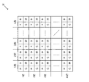
撮像素子12が撮像できる範囲となる撮像領域は、可視光領域と赤外光領域とに分割されている。可視光領域と赤外光領域とに分割された撮像領域の詳細な構成を図2に示す。
An imaging region that is a range that can be imaged by the
図2に示したように、撮像素子12の撮像領域には、可視光および赤外光を検知する画素がm行n列に配列されている。m行n列に配列される画素群は、予め決まっている可視光領域と赤外光領域とに分割されている。例えば、1列目〜k列目にある画素が可視光領域と設定され、k列目〜n列目にある画素を赤外光領域と設定される。なお、kは1〜nにある値である。
As shown in FIG. 2, pixels that detect visible light and infrared light are arranged in m rows and n columns in the imaging region of the
各画素は、可視光におけるR(赤)、B(青)、およびG(緑)の成分を検知するように構成されていると共に、近赤外光IRにおける成分を検知するように構成されている。なお、可視光においては、R、B、Gに替えて、Cy(シアン)、Ye(黄)、Mg(マゼンダ)にしてもよい。 Each pixel is configured to detect R (red), B (blue), and G (green) components in visible light and configured to detect components in near-infrared light IR. Yes. In visible light, instead of R, B, and G, Cy (cyan), Ye (yellow), and Mg (magenta) may be used.
映像信号処理手段13は、情報処理回路などによって構成され、撮像素子12から出力された映像信号を処理するようになっている。映像信号処理手段13は、可視光領域にある画素によって出力される映像信号からR、B、Gの成分の映像信号を処理するようになっている。また、映像信号処理手段13は、赤外光領域にある画素によって出力される映像信号からIRの成分の映像信号を処理するようになっている。
The video signal processing means 13 is constituted by an information processing circuit or the like, and processes the video signal output from the
また、映像信号処理手段13は、映像信号に対してノイズ除去やゲイン調整を行ったり、映像信号に対して補正処理を行う。映像信号処理手段13が出力した映像信号は、撮像装置10と同じ車両に搭載されるディスプレイなどに表示される。
The video signal processing means 13 performs noise removal and gain adjustment on the video signal, and performs correction processing on the video signal. The video signal output by the video signal processing means 13 is displayed on a display or the like mounted on the same vehicle as the
図3は、車載のディスプレイが表示する映像を表した図である。図3に示すように、ディスプレイ30には、地平線33の上に人31の映像が表示されており、さらに、地平線33の下に片側1車線32の映像が表示されている。
FIG. 3 is a diagram showing an image displayed on the in-vehicle display. As shown in FIG. 3, the
ここで、図3の映像の領域を、地平線33を境界にして路面上にある領域である上領域34と路面が映る領域である下領域35とに分割するものとし、上領域34に対応するように赤外光領域が設定され、下領域35に対応するように可視光領域が設定されるものとする。このように設定すれば、車両が夜間走行している最中に、運転者が、上領域34の人31がいることを赤外光による映像で確認することができ、下領域35にある車線32の白線などを可視光による映像で確認することができる。
3 is divided into an
以上のように構成された本発明の第1の実施の形態に係る撮像装置の動作について説明する。図4は、本発明の第1の実施の形態に係る撮像装置の映像信号処理手段の動作を示すフローチャートである。 The operation of the imaging apparatus according to the first embodiment of the present invention configured as described above will be described. FIG. 4 is a flowchart showing the operation of the video signal processing means of the imaging apparatus according to the first embodiment of the present invention.
まず、映像信号処理手段13は、撮像素子12のm行n列に配列された各画素から映像信号を順に取り込み(ステップS11)、次に、取り込んだ映像信号の画素が可視光領域にあるものか赤外光領域にあるものかを判定する(ステップS12)。 First, the video signal processing means 13 sequentially captures video signals from the pixels arranged in m rows and n columns of the image sensor 12 (step S11), and then the captured video signal pixels are in the visible light region. Or in the infrared light region (step S12).
取り込んだ映像信号の画素が可視光領域にある場合、映像信号処理手段13は、IRの成分の映像信号の処理を行わず、R、B、Gの成分の映像信号だけを処理する(ステップS13)。取り込んだ映像信号の画素が赤外光領域にある場合、映像信号処理手段13は、R、B、Gの成分の映像信号の処理を行わず、IRの成分の映像信号だけを処理する(ステップS14)。 When the captured video signal pixel is in the visible light region, the video signal processing means 13 does not process the IR component video signal, but processes only the R, B, and G component video signals (step S13). ). When the captured video signal pixel is in the infrared light region, the video signal processing means 13 does not process the R, B, and G component video signals, but only processes the IR component video signals (steps). S14).
以上説明したように、本発明の第1の実施の形態に係る撮像装置は、撮像領域のうち可視光で見たい領域には可視光領域が設定され、赤外光で見たい領域には赤外光領域が設定され、可視光領域に対応する画素から出力される映像信号に対しては可視光の映像信号だけを処理し、赤外光領域に対応する画素から出力される映像信号に対しては赤外光の映像信号だけを処理するため、夜間などの状況で物体を視認させやすくすることができる。また、カメラを複数台使用することなく1台のカメラで実現できる。 As described above, in the imaging device according to the first embodiment of the present invention, a visible light region is set in a region desired to be seen with visible light in the imaging region, and red is designated in a region desired to be seen with infrared light. For the video signal output from the pixel corresponding to the visible light region with the outside light region set, only the visible light video signal is processed, and the video signal output from the pixel corresponding to the infrared light region is processed. Since only the infrared video signal is processed, the object can be easily seen in the nighttime situation. Further, it can be realized by one camera without using a plurality of cameras.
図3の映像領域では、地平線33を境界にして上領域34に対応する赤外光領域と、可視光領域に対応する下領域35とに分割するものとしたが、映像領域のうち自車線の路面が映ると想定される領域を可視光領域とし、可視光領域でない領域を赤外光領域としてもよい。また、自車両から一定距離(30mもしくは80m)が離れた路面が映ると想定される領域を可視光領域とし、可視光領域でない領域を赤外光領域としてもよい。
また、車両の可視光ヘッドライトの光の到達範囲を可視光領域とし、可視光領域でない領域を赤外光領域としてもよい。さらに、可視光ヘッドライトのハイビームまたはロービームの切替えに連動して可視光領域および赤外光領域の範囲がハイビームまたはロービームの光の到達範囲に対応するよう変更されてもよい。
In the video area of FIG. 3, it is divided into an infrared light area corresponding to the
Further, the reachable range of the visible light headlight of the vehicle may be the visible light region, and the region that is not the visible light region may be the infrared light region. Furthermore, the range of the visible light region and the infrared light region may be changed to correspond to the arrival range of the light of the high beam or the low beam in conjunction with the switching of the high beam or the low beam of the visible light headlight.
また、最近では、ハイビームと兼用の近赤外線投光器を車両に搭載し、赤外線投光器から近赤外線を車両の進行方向の前方に照射し、夜間走行している車両の進行方向の前方を赤外線カメラで撮影し、赤外線カメラで車両の進行方向の前方にある物体を検知することで、夜間でも歩行者などを検知するものがある。このように近赤外線投光器を搭載した車両が対向車として現れると、撮像装置10は、赤外光領域で対向車を視認させることが困難となってしまう。このため、図5に示すように、近赤外線投光器52を有する対向車51が映ると想定される領域を可視光領域とし、可視光領域でない領域を赤外光領域としてもよい。なお、図5に示すように、可視光領域と赤外光領域との間に破線で示している境界線を示している。
Recently, a near-infrared projector that is also used as a high beam is mounted on the vehicle, and the infrared projector emits near-infrared light in front of the traveling direction of the vehicle. However, there is an infrared camera that detects a pedestrian or the like even at night by detecting an object in front of the traveling direction of the vehicle. Thus, when a vehicle equipped with a near-infrared projector appears as an oncoming vehicle, it becomes difficult for the
撮像装置10は、対向車の有無を判定できるセンサなどを設け、対向車が無い場合は撮像領域全てを赤外光領域とし、対向車があった場合だけ対向車が映ると想定される領域を可視光領域とするよう、可視光領域を切り替えてもよい。
The
(本発明の第2の実施の形態)
図6は、本発明の第2の実施の形態に係る撮像装置のブロック図である。撮像装置20は、光を集光して被写体を結像するためのレンズ11、レンズ11から集光された光を映像信号に変換する撮像素子22、撮像素子22によって変換された映像信号を処理する映像信号処理手段23、赤外光領域に対応した可視光カットフィルタ24および可視光領域に対応した赤外光カットフィルタ25によって構成されている。撮像装置20は、例えば、車両の進行方向を撮像するように車両に設置されている。
(Second embodiment of the present invention)
FIG. 6 is a block diagram of an imaging apparatus according to the second embodiment of the present invention. The
赤外光カットフィルタ25は、撮像素子22の撮像領域を分割した可視光領域に対応する位置に配置されている。可視光カットフィルタ24は、撮像素子22の撮像領域を分割した赤外光領域に対応する位置に配置されている。
The infrared light cut
撮像素子22が撮像できる範囲となる撮像領域は、可視光領域と赤外光領域とに分割されている。撮像素子22は、CMOS(Complementary Metal Oxide Semiconductor)センサーなど構成されており、撮像素子12のように同一画素内に同時に赤外光と可視光とを検知できるものではない。
An imaging region that is a range that can be imaged by the
映像信号処理手段23は、情報処理回路などによって構成され、撮像素子22から出力された映像信号を処理するようになっている。なお、映像信号処理手段23は、映像信号処理手段13に説明したように、可視光領域にある画素および赤外光領域にある画素を区別して映像信号を処理することはない。
The video signal processing means 23 is constituted by an information processing circuit or the like, and processes the video signal output from the
また、映像信号処理手段23は、映像信号に対してノイズ除去やゲイン調整を行ったり、映像信号に対して補正処理を行う。映像信号処理手段23が出力した映像信号は、撮像装置20と同じ車両に搭載されるディスプレイなどに表示される。
The video signal processing means 23 performs noise removal and gain adjustment on the video signal, and performs correction processing on the video signal. The video signal output from the video signal processing means 23 is displayed on a display or the like mounted on the same vehicle as the
図3は、車載のディスプレイが表示する映像を表した図である。赤外光カットフィルタ25は、下領域35の可視光領域に対応するような位置に配置され、可視光カットフィルタ24は、上領域34の赤外光領域に対応するような位置に配置される。
FIG. 3 is a diagram showing an image displayed on the in-vehicle display. The infrared light cut
赤外光カットフィルタ25は、映像領域のうち自車線の路面が映ると想定される可視光領域に対応するような位置に配置されてもよく、可視光カットフィルタ24は、可視光領域でない赤外光領域に対応するような位置に配置されてもよい。また、赤外光カットフィルタ25は、対向車が映ると想定される可視光領域に対応するような位置に配置されてもよい。
The infrared light cut
以上説明したように、本発明の第2の実施の形態に係る撮像装置は、可視光領域に対応した赤外光カットフィルタ25および赤外光領域に対応した可視光カットフィルタ24を備え、可視光領域に対応する光を赤外光カットフィルタ25で除去することで可視光の映像信号だけを処理し、赤外光領域に対応する光を可視光カットフィルタ24で除去することで赤外光の映像信号だけを処理するため、夜間などの状況で物体を視認させやすくすることができる。
As described above, the imaging apparatus according to the second embodiment of the present invention includes the infrared light cut
以上のように、本発明は、夜間などの状況で物体を視認させやすくすることができるという効果を有し、車両などに設置される撮像装置等として有用である。 As described above, the present invention has an effect of making it easy to visually recognize an object in a situation such as nighttime, and is useful as an imaging device or the like installed in a vehicle or the like.
10、20 撮像装置
11 レンズ
12、22 撮像素子
13、23 映像信号処理手段
24 可視光カットフィルタ
25 赤外光カットフィルタ
30 ディスプレイ
31 人
32 車線
33 地平線
34 上領域
35 下領域
DESCRIPTION OF
Claims (6)
前記撮像素子から出力された前記可視光領域に対応した可視光の映像信号および前記赤外光領域に対応した赤外光の映像信号を処理する映像信号処理手段と、
を備えたことを特徴とする撮像装置。 An imaging device divided into a visible light region and an infrared light region;
Video signal processing means for processing a visible light video signal corresponding to the visible light region and an infrared light video signal corresponding to the infrared light region output from the imaging device;
An imaging apparatus comprising:
前記映像信号処理手段が、前記可視光領域に対応する前記撮像素子の画素から出力される映像信号に対しては前記可視光の映像信号を処理し、前記赤外光領域に対応する前記撮像素子の画素から出力される映像信号に対しては前記赤外光の映像信号を処理することを特徴とする請求項1に記載の撮像装置。 In the imaging device, pixels that detect visible light and infrared light are arranged, the pixels output the video signal of the visible light and the video signal of the infrared light,
The video signal processing means processes the video signal of the visible light for a video signal output from a pixel of the image sensor corresponding to the visible light region, and the image sensor corresponding to the infrared light region. The imaging apparatus according to claim 1, wherein the image signal of the infrared light is processed for an image signal output from the pixel.
前記撮像素子の撮像領域のうち、前記周囲にある路面が映ると想定される領域を前記可視光領域とし、該可視光領域でない領域を前記赤外光領域とすることを特徴とする請求項2に記載の撮像装置。 The image sensor is installed to image the surroundings of the vehicle;
3. The imaging region of the imaging device, wherein a region where the surrounding road surface is assumed to be reflected is the visible light region, and a region that is not the visible light region is the infrared light region. The imaging device described in 1.
前記撮像素子の撮像領域のうち、前記前方にある対向車が映ると想定される領域を前記可視光領域とし、該可視光領域でない領域を前記赤外光領域とすることを特徴とする請求項2に記載の撮像装置。 The image sensor is installed to image the front of the vehicle in the traveling direction;
The region that is assumed to show the oncoming vehicle in front of the imaging device is the visible light region, and the region that is not the visible light region is the infrared light region. 2. The imaging device according to 2.
前記可視光領域に対応した赤外光カットフィルタおよび前記赤外光領域に対応した可視光カットフィルタを前記レンズと前記撮像素子との間に備えたことを特徴とする請求項1に記載の撮像装置。 A lens for condensing light and imaging the subject;
The imaging according to claim 1, further comprising an infrared light cut filter corresponding to the visible light region and a visible light cut filter corresponding to the infrared light region between the lens and the imaging element. apparatus.
前記撮像素子の撮像領域のうち、前記車両の可視光ヘッドライトの光の到達範囲を前記可視光領域とし、該可視光領域でない領域を前記赤外光領域とすることを特徴とする請求項2に記載の撮像装置。 The image sensor is installed to image the front of the vehicle in the traveling direction;
3. The reachable range of the visible light headlight of the vehicle among the image pickup areas of the image pickup device is defined as the visible light area, and an area other than the visible light area is defined as the infrared light area. The imaging device described in 1.
Priority Applications (2)
| Application Number | Priority Date | Filing Date | Title |
|---|---|---|---|
| JP2007257819A JP2009089158A (en) | 2007-10-01 | 2007-10-01 | Imaging apparatus |
| PCT/JP2008/002757 WO2009044544A1 (en) | 2007-10-01 | 2008-10-01 | Imaging device |
Applications Claiming Priority (1)
| Application Number | Priority Date | Filing Date | Title |
|---|---|---|---|
| JP2007257819A JP2009089158A (en) | 2007-10-01 | 2007-10-01 | Imaging apparatus |
Publications (1)
| Publication Number | Publication Date |
|---|---|
| JP2009089158A true JP2009089158A (en) | 2009-04-23 |
Family
ID=40525976
Family Applications (1)
| Application Number | Title | Priority Date | Filing Date |
|---|---|---|---|
| JP2007257819A Pending JP2009089158A (en) | 2007-10-01 | 2007-10-01 | Imaging apparatus |
Country Status (2)
| Country | Link |
|---|---|
| JP (1) | JP2009089158A (en) |
| WO (1) | WO2009044544A1 (en) |
Cited By (9)
| Publication number | Priority date | Publication date | Assignee | Title |
|---|---|---|---|---|
| JP2011082856A (en) * | 2009-10-08 | 2011-04-21 | Hoya Corp | Imaging apparatus |
| JP2011081657A (en) * | 2009-10-08 | 2011-04-21 | Hoya Corp | Imaging system |
| JP2011082855A (en) * | 2009-10-08 | 2011-04-21 | Hoya Corp | Imaging apparatus |
| JP2011222900A (en) * | 2010-04-14 | 2011-11-04 | Hamamatsu Photonics Kk | Solid-state imaging apparatus |
| US8896744B2 (en) | 2011-03-16 | 2014-11-25 | Kabushiki Kaisha Toshiba | Solid-state imaging device and camera module with IR filter having wavelength characteristics to block both IR and selected visible light band depending on detection target of pixel cells |
| WO2017217053A1 (en) * | 2016-06-17 | 2017-12-21 | シャープ株式会社 | Imaging device and filter |
| KR20180037557A (en) * | 2016-10-04 | 2018-04-12 | 삼성전기주식회사 | Iris scan camera module and mobile device including the same |
| JP2019189384A (en) * | 2018-04-23 | 2019-10-31 | トーヨーカネツソリューションズ株式会社 | Block mechanism of transport device |
| US10763295B2 (en) | 2016-06-15 | 2020-09-01 | Sony Corporation | Imaging apparatus and electronic device |
Families Citing this family (4)
| Publication number | Priority date | Publication date | Assignee | Title |
|---|---|---|---|---|
| EP2464124A1 (en) * | 2010-12-13 | 2012-06-13 | Research In Motion Limited | System and method of capturing low-light images on a mobile device |
| JP5904825B2 (en) * | 2012-03-05 | 2016-04-20 | 本田技研工業株式会社 | Image processing device |
| CN106856374A (en) | 2017-03-08 | 2017-06-16 | 浙江驰力科技股份有限公司 | Low-frequency alternating electric field generation device and system, Signal Regulation method |
| JP6747465B2 (en) * | 2018-03-06 | 2020-08-26 | 株式会社ニコン | Electronics |
Family Cites Families (6)
| Publication number | Priority date | Publication date | Assignee | Title |
|---|---|---|---|---|
| JPH11132860A (en) * | 1997-10-28 | 1999-05-21 | Matsushita Electric Ind Co Ltd | Solid imaging device |
| JP2001189926A (en) * | 1999-12-28 | 2001-07-10 | Mitsubishi Electric Corp | Image pickup device for road monitor |
| JP3909691B2 (en) * | 2002-09-12 | 2007-04-25 | 株式会社日立製作所 | In-vehicle image processing device |
| JP4678172B2 (en) * | 2004-11-22 | 2011-04-27 | 株式会社豊田中央研究所 | Imaging device |
| JP4932293B2 (en) * | 2006-03-23 | 2012-05-16 | 本田技研工業株式会社 | Obstacle recognition device |
| JP2007124676A (en) * | 2006-11-22 | 2007-05-17 | Hitachi Ltd | On-vehicle image processor |
-
2007
- 2007-10-01 JP JP2007257819A patent/JP2009089158A/en active Pending
-
2008
- 2008-10-01 WO PCT/JP2008/002757 patent/WO2009044544A1/en active Application Filing
Cited By (11)
| Publication number | Priority date | Publication date | Assignee | Title |
|---|---|---|---|---|
| JP2011082856A (en) * | 2009-10-08 | 2011-04-21 | Hoya Corp | Imaging apparatus |
| JP2011081657A (en) * | 2009-10-08 | 2011-04-21 | Hoya Corp | Imaging system |
| JP2011082855A (en) * | 2009-10-08 | 2011-04-21 | Hoya Corp | Imaging apparatus |
| JP2011222900A (en) * | 2010-04-14 | 2011-11-04 | Hamamatsu Photonics Kk | Solid-state imaging apparatus |
| US8896744B2 (en) | 2011-03-16 | 2014-11-25 | Kabushiki Kaisha Toshiba | Solid-state imaging device and camera module with IR filter having wavelength characteristics to block both IR and selected visible light band depending on detection target of pixel cells |
| US10763295B2 (en) | 2016-06-15 | 2020-09-01 | Sony Corporation | Imaging apparatus and electronic device |
| WO2017217053A1 (en) * | 2016-06-17 | 2017-12-21 | シャープ株式会社 | Imaging device and filter |
| JPWO2017217053A1 (en) * | 2016-06-17 | 2019-01-31 | シャープ株式会社 | Image pickup apparatus and filter |
| CN109313379A (en) * | 2016-06-17 | 2019-02-05 | 夏普株式会社 | Image pickup device and optical filter |
| KR20180037557A (en) * | 2016-10-04 | 2018-04-12 | 삼성전기주식회사 | Iris scan camera module and mobile device including the same |
| JP2019189384A (en) * | 2018-04-23 | 2019-10-31 | トーヨーカネツソリューションズ株式会社 | Block mechanism of transport device |
Also Published As
| Publication number | Publication date |
|---|---|
| WO2009044544A1 (en) | 2009-04-09 |
Similar Documents
| Publication | Publication Date | Title |
|---|---|---|
| JP2009089158A (en) | Imaging apparatus | |
| US8767074B2 (en) | System and method of assisting visibility of driver | |
| US11228700B2 (en) | Vehicle vision system camera with adaptive field of view | |
| JP5171723B2 (en) | Obstacle detection device and vehicle equipped with the device | |
| JP7370413B2 (en) | Solid-state imaging devices and electronic equipment | |
| TWI757419B (en) | Camera device, camera module and camera control method | |
| WO2013140873A1 (en) | In-vehicle image processing device and method | |
| JP5951785B2 (en) | Image processing apparatus and vehicle forward monitoring apparatus | |
| KR20230116082A (en) | Imaging apparatus and electronic device | |
| JP4798945B2 (en) | Imaging device | |
| JP2001174696A (en) | Color image pickup unit | |
| JP2006254318A (en) | Vehicle-mounted camera, vehicle-mounted monitor and forward road area imaging method | |
| JP2014026396A (en) | Movable surface boundary line recognition device, movable body having movable surface boundary line recognition device, movable surface boundary line recognition method, and movable surface boundary line recognition program | |
| JP2006178652A (en) | Vehicle environment recognition system and image processor | |
| JP2001257923A (en) | Image pickup device | |
| JP2013250694A (en) | Image processing apparatus | |
| JP4795813B2 (en) | Vehicle perimeter monitoring device | |
| JP2007329749A (en) | Imaging element, imaging apparatus, and image processor | |
| JP4723934B2 (en) | Object search device | |
| US20200213486A1 (en) | Vehicle camera system and method | |
| JP2006024120A (en) | Image processing system for vehicles and image processor | |
| JPH09231379A (en) | Device for recognizing traveling lane by picture processing | |
| WO2023286297A1 (en) | Solid-state imaging element, imaging device, and method for controlling solid-state imaging element | |
| WO2023100640A1 (en) | Semiconductor device, signal processing method, and program | |
| TW202416721A (en) | Solid-state imaging device and electronic device |