JP2009079773A - One-way ratchet clutch assembly - Google Patents
One-way ratchet clutch assembly Download PDFInfo
- Publication number
- JP2009079773A JP2009079773A JP2008311102A JP2008311102A JP2009079773A JP 2009079773 A JP2009079773 A JP 2009079773A JP 2008311102 A JP2008311102 A JP 2008311102A JP 2008311102 A JP2008311102 A JP 2008311102A JP 2009079773 A JP2009079773 A JP 2009079773A
- Authority
- JP
- Japan
- Prior art keywords
- pawl
- spring
- claw
- clutch assembly
- members
- Prior art date
- Legal status (The legal status is an assumption and is not a legal conclusion. Google has not performed a legal analysis and makes no representation as to the accuracy of the status listed.)
- Pending
Links
Images


Landscapes
- Mechanical Operated Clutches (AREA)
Abstract
Description
本発明は、遠心力によって係合し/離脱する爪と、非鉄材料で出来たステータとを備えるワンウエイラチェットクラッチ組立体に関する。 The present invention relates to a one-weiler check clutch assembly comprising a pawl that engages / disengages by centrifugal force and a stator made of a non-ferrous material.
今日、種々の型式のワンウェイクラッチ組立体が使用されている。かかるクラッチ組立体は、スプラグ型、ローラ型、及び爪ラチェット型の組立体を含む。これらワンウェイクラッチ組立体の全ては、これら組立体が使用される特定の用途に対応して満足し得るように機能する。 Various types of one-way clutch assemblies are in use today. Such clutch assemblies include sprag, roller, and claw ratchet assemblies. All of these one-way clutch assemblies function satisfactorily for the specific application in which they are used.
特定の伝動装置において、ワンウェイクラッチ組立体について大きいトルク能力が必要とされる。更に、スペース上の制約のため、クラッチ組立体の寸法を特定の制限値内に保つことも必要である。スプラグ又はローラを有する現在のワンウェイクラッチ組立体は、負荷伝達能力を更に増し、しかもスペース上の制約を満たすには不十分であることがしばしばである。 In certain transmissions, a large torque capacity is required for the one-way clutch assembly. Furthermore, due to space constraints, it is also necessary to keep the clutch assembly dimensions within certain limits. Current one-way clutch assemblies with sprags or rollers are often insufficient to further increase load transfer capacity and meet space constraints.
爪ワンウェイクラッチ組立体は、所定の配置寸法にて公称負荷能力を更に増すことができる。ラチェット型爪クラッチ組立体の設計上の制約は、爪とレースとの間の接触応力及び/又はレース内にて発生される曲げ応力、せん断応力及びフープ応力によって決まる。 The pawl one-way clutch assembly can further increase the nominal load capacity at a given geometry. The design constraints of the ratchet pawl clutch assembly are determined by the contact stress between the pawl and the race and / or the bending, shear and hoop stresses generated within the race.
ラチェット組立体は、2つの切欠き付き又は空所付きレースを共に一方向に係止し、反対方向に自由に回転させる働きをする少なくとも1つの爪を有している。一般に、公知のラチェット組立体間の相違点は、爪の動作を制御し且つその動作に対する遠心力の影響を制御する点にある。ラチェットクラッチ組立体は、例えば、米国特許第2,226,247号、同第3,554,340号、及び同第5,449,057号に記載されている。別のラチェットクラッチ組立体は、英国特許第2116号に記載されている。 The ratchet assembly has at least one pawl that serves to lock the two notched or voided races together in one direction and to rotate freely in opposite directions. In general, the difference between known ratchet assemblies is to control the movement of the pawl and to control the effect of centrifugal force on that movement. Ratchet clutch assemblies are described, for example, in U.S. Pat. Nos. 2,226,247, 3,554,340, and 5,449,057. Another ratchet clutch assembly is described in GB 2116.
本発明の1つの目的は、改良に係るワンウェイラチェットクラッチ組立体を提供することである。本発明の更に別の目的は、高速度時の作動が改良された、改良に係るラチェットクラッチ組立体を提供することである。 One object of the present invention is to provide an improved one-way ratchet clutch assembly. Yet another object of the present invention is to provide an improved ratchet clutch assembly with improved operation at high speeds.
本発明の目的は、係合方向に向けて爪に対し傾動力又は傾斜力が与えられるワンウェイラチェット組立体を提供することである。本発明の更に別の目的は、爪に対し係合方向への傾動力を与えるためばねを利用するワンウェイラチェット組立体を提供することである。 An object of the present invention is to provide a one-way ratchet assembly in which tilting power or tilting force is applied to the pawl in the engagement direction. Yet another object of the present invention is to provide a one-way ratchet assembly that utilizes a spring to provide tilting force in the direction of engagement to the pawl.
本発明の更なる目的は、公知の組立体よりも低廉で且つ軽量であり、しかも、作用及び性能の点にて同等である、改良に係るラチェットクラッチ組立体を提供することである。本発明の更に別の目的は、堅固で耐久性があり且つ軽量な、プラスチック又はアルミニウムのような非鉄材料で出来たワンウエイラチェットクラッチ組立体を提供することである。 It is a further object of the present invention to provide an improved ratchet clutch assembly that is cheaper and lighter than known assemblies and that is equivalent in operation and performance. It is yet another object of the present invention to provide a one-weiler ratchet clutch assembly made of a non-ferrous material such as plastic or aluminum that is rigid, durable and lightweight.
本発明の追加的な目的は、係合方向に向けて爪に傾動力を付与するためばねを利用するワンウエイラチェットクラッチ組立体を提供することである。本発明の1つの目的は、外側レース部材がステータ/リアクタ部材内に直接、組み込まれ又はそのステータ/リアクタ部材の一部である、ワンウエイラチェットクラッチ組立体を提供することである。 An additional object of the present invention is to provide a one-weiler check clutch assembly that utilizes a spring to impart tilting power to the pawl in the direction of engagement. One object of the present invention is to provide a one-way ratchet clutch assembly in which the outer race member is incorporated directly into or is part of the stator / reactor member.
本発明の上記及びその他の目的は、公知のワンウエイラチェットクラッチ組立体に優る改良である、本発明により達成される。 These and other objects of the present invention are achieved by the present invention, which is an improvement over known one-way ratchet clutch assemblies.
本発明は、外側レースの空所内に配置された複数の爪と、クラッチ組立体を形成するステータすなわちリアクタとを備える、ワンウエイラチェットクラッチ組立体を提供するものである。対応する複数の歯付き切欠きが内側レース部材の外周に配置されて、レースすなわち内側レース及びステータが一方向に相対的に回転する間、爪と係止係合状態にて合わさる。切欠きは、レース部材の外側に歯を保持しており、該歯は、外側レースすなわちステータが一方向に回転するのは防止するが、反対方向にフライホイール回転するのを許容する形状とされている。内側レース部材の内径は、車の伝動装置の静止支持軸のような、支持軸と合わさり且つ該支持軸に対し確実に配置され得るようにされている。 The present invention provides a one-way ratchet clutch assembly comprising a plurality of pawls disposed within an outer race cavity and a stator or reactor forming a clutch assembly. A plurality of corresponding toothed notches are disposed on the outer periphery of the inner race member and engage in engagement with the pawl while the race or inner race and stator rotate relative to one direction. The notch holds the teeth on the outside of the race member, and the teeth are shaped to prevent the outer race or stator from rotating in one direction but allowing the flywheel to rotate in the opposite direction. ing. The inner race member has an inner diameter that is aligned with the support shaft, such as a stationary support shaft of a vehicle transmission, so that it can be reliably positioned with respect to the support shaft.
爪は、外側レースすなわちステータ部材の空所の回動リッジ又は凹所と合わさる頂部又はリッジを有する。爪の質量中心は、所望に応じて配置し又は位置決めし、クラッチが回転するとき、質量中心に加わる遠心力によって、爪は係合位置又は離脱位置に向けて動くようにすることができる。このことは、回転軸又は静止回動点を使用せずに行われる。 The pawl has a top or ridge that mates with an outer race or pivot ridge or recess in the stator member cavity. The center of mass of the pawl can be positioned or positioned as desired, and the pawl can move toward the engaged or disengaged position by centrifugal force applied to the center of mass when the clutch rotates. This is done without using a rotating shaft or stationary pivot point.
本発明の幾つかの実施の形態において、ガーターばね、コイルばね、リボンばね、Z字形ばね、個々の板ばね等のようなばね部材を使用して内側レース部材の切欠きとの係合方向に向けて爪に対し傾動又は偏倚力を提供する。このばね力は、爪の1つ以上の周溝に付与することができ、又は、ばね力は、爪部材自体に作用し、又は爪に沿って軸方向に伸長する凹所内に作用することができる。好ましくは、ばね部材は爪部材の長さに沿って伸長する幅の広いz字形ばねであるようにする。 In some embodiments of the present invention, spring members such as garter springs, coil springs, ribbon springs, Z-shaped springs, individual leaf springs, etc. are used in the direction of engagement with the notches of the inner race member. Provide tilting or biasing force toward the nails. This spring force can be applied to one or more circumferential grooves of the pawl, or the spring force can act on the pawl member itself or in a recess that extends axially along the pawl. it can. Preferably, the spring member is a wide z-shaped spring extending along the length of the pawl member.
好ましくは、ステータ部材は、クラッチ組立体、特に、外側レース部材について従来から使用されている材料よりも軽量である非鉄材料で出来ているものとする。非鉄材料は、クラッチ組立体を作用させるのに必要な耐久性及び強度基準に適合する、アルミニウムのような金属材料又はポリエチレンのようなプラスチック材料とすることができる。 Preferably, the stator member is made of a non-ferrous material that is lighter in weight than materials conventionally used for clutch assemblies, particularly outer race members. The non-ferrous material can be a metallic material such as aluminum or a plastic material such as polyethylene that meets the durability and strength criteria required to operate the clutch assembly.
外側レースすなわちステータ空所内のリッジは、係合力を制御し得るように爪の質量中心に対して配置されている。このことは、高速度時の耐久性を得るために必要である。この点に関して、本発明の一つの代替的な実施の形態に従い、爪が係合位置に向けて、又は係合も離脱もしない「中立位置」に向けてさえも付勢されるように、質量中心を位置決めすることが可能である。 The ridge in the outer race or stator cavity is located relative to the center of mass of the pawl so that the engagement force can be controlled. This is necessary to obtain durability at high speeds. In this regard, according to one alternative embodiment of the present invention, the mass is such that the pawl is biased towards the engaged position or even towards the “neutral position” where it is neither engaged nor disengaged. It is possible to position the center.
本発明と共に使用可能なその他のばね部材は、ガーターばね、コイルばね、Z字形折重ねばね及びリボンばねを含む。ばね力は、爪部材の中央溝に、又は1つ以上の側部溝に付与することができ、又は、ばね力は、爪部材自体に作用し、又は爪の長さに沿って軸方向に伸びる凹所内に作用することができる。 Other spring members that can be used with the present invention include garter springs, coil springs, Z-shaped fold springs and ribbon springs. The spring force can be applied to the central groove of the pawl member or to one or more side grooves, or the spring force acts on the pawl member itself or axially along the length of the pawl. It can act in the extending recess.
本発明のその他の実施の形態は、1つ以上の軸方向保持装置を利用する。これらの装置は、一対の座金とし、又は軸方向に伸びるフランジ部材を有するプラスチック製リテーナを含む。該装置は、爪を軸方向に保持し、また、相対的回転を許容しつつ、レースを軸方向半径方向に整合する位置に保持する。また、該保持装置は、スラストベアリングとしても作用し、爪の過度の摩耗を防止するため必要とされる潤滑剤を保持することができる。 Other embodiments of the present invention utilize one or more axial retention devices. These devices include a pair of washers or a plastic retainer having an axially extending flange member. The device holds the pawl in the axial direction and holds the race in a position that aligns in the axial radial direction while allowing relative rotation. The holding device also acts as a thrust bearing, and can hold the lubricant required to prevent excessive wear of the claws.
クラッチ組立体の外側レース部材を省き且つ爪空所を直接、ステータすなわちリアクタ機構又はその他の同様の部材に内蔵することにより、材料及び製造方法の費用を削減できる。同様に、内側レース部材を省き且つ切欠きは直接、中心軸部材等に含めることができる。この場合にも、このことは、材料、製造時間及び費用を削減することになる。 By eliminating the outer race member of the clutch assembly and incorporating the claw cavity directly into the stator or reactor mechanism or other similar member, material and manufacturing costs can be reduced. Similarly, the inner race member can be omitted and the notch can be included directly in the central shaft member or the like. Again, this will reduce material, manufacturing time and costs.
本発明のワンウェイラチェットクラッチ組立体は、車の伝動装置にて特に使用されるものであり、また、双方のレースが回転し又はレースの1つが固定された環境内にて使用することができる。また、本発明は、エスカレータ機構等のような望まない逆回転又は後方回転を防止するために確実な逆回転ストッパが望まれる任意の機構にて使用することもできる。 The one-way ratchet clutch assembly of the present invention is particularly used in vehicle transmissions and can be used in environments where both races are rotating or one of the races is fixed. The present invention can also be used in any mechanism where a reliable reverse rotation stopper is desired to prevent unwanted reverse or backward rotation, such as an escalator mechanism.
本発明の他の特徴、利点及び有利な点は、添付図面及び特許請求の範囲に従って検討するならば、本発明の以下の説明から明らかになるであろう。 Other features, advantages and advantages of the invention will become apparent from the following description of the invention when considered in accordance with the accompanying drawings and claims.
図1には、本発明によるワンウェイラチェットクラッチ組立体20の一形式が概略図で示してある。この組立体20は、内側レース22と、外側レース24と、複数の個々の爪部材25とを備えている。この爪部材25は、外側レース部材の空所26内に配置されている。複数の切欠き28が内側レース22の外周又は周縁に配置されている。切欠き歯を提供し、その歯は二つのレースが互いに一方の方向に回転するのを阻止するが他の方向には回転を許容するように形成されている。
FIG. 1 schematically illustrates one form of a one-way
外側レース部材24に関して内側レース22が図1で時計方向に向けて動くならば、内側レースは自由回転する。外側レース部材24に関し内側レース部材22が相対的に反時計方向に動くならば、内側レース及び外側レースは、爪25の1つにより共に係止される。この点に関して、図1において、係止した爪は、参照番号25′で示してある。爪25′は、外側レース部材の空所26及び内側レース部材の切欠き28を通じて力を伝達する。
If the
図1に示した、クラッチ組立体において、10個の空所26と、10個の爪部材25が、内側レース22の11個の切欠き28と共に示してある。図1に図示した実施の形態では係合した1つの爪25′しか示さないが、製造公差と共に、爪及び切欠きの相対数及び位置に応じて、1つより多い爪を同時に係合させることができる。数学的には、もし爪及び切欠きの数が両者とも1以外の共通の分母により割けれれば、一つ以上の爪部材が係合され得る。
In the clutch assembly shown in FIG. 1, ten
図2は、図1に示したクラッチ組立体の一部分の拡大図である。図2に示した爪25は、自在回転位置にて示してある。本発明によれば、爪25の断面は、略平坦な2つの側面32、34が交差することにより形成された頂部又は回動リッジ30を有している。この断面の頂部30は、爪を受け入れ得る形状とされた外側レースの空所26と共に、回動リッジを形成する。この点に関して、空所26は、略直線状の側面36、37、38、39を有している。
FIG. 2 is an enlarged view of a portion of the clutch assembly shown in FIG. The
図2に示される実施例にしたがって、爪部材25の質量中心(CM)は回動リッジの左にある。爪部材は、次のように形成することができる、すなわち、正確な質量中心(CM)を回動リッジに対する所望の位置に配置し、これにより、特定の用途に必要とされるクラッチ組立体の作用に影響し得るように配置することができる。例えば、図2に図示するように、爪25の質量中心(CM)は回動リッジ30の左側に配置されている。このようにして、クラッチ組立体20が回転するとき、質量中心(CM)に加わる遠心力(CF)により、爪25は係合位置、すなわち爪25が内側レース22の切欠き28に係合する位置に向けて動く。爪25に加わるトルクは、リッジ30から離れるCMの接線方向距離に比例する。
According to the embodiment shown in FIG. 2, the center of mass (CM) of the
図1及び図2に示した本発明の実施の形態は、外側レースの空所と共に、質量中心が配置された爪部材が示されており、この場合、爪は係合位置に向けて動く傾向となるが、本発明に従って、他の実施の形態も利用することもできる。例えば、爪の幾何学的形態は、爪が非係合状態となる傾向となるように変更することができる。このように、CMは、回動リッジ30の右側に配置することも可能である。
The embodiment of the present invention shown in FIGS. 1 and 2 shows a pawl member with a center of mass disposed along with a void in the outer race, where the pawl tends to move toward the engaged position. However, other embodiments may be utilized in accordance with the present invention. For example, the nail geometry can be changed so that the nail tends to be disengaged. In this way, the CM can be arranged on the right side of the
外側レースの空所26は、更に、爪部材25の回動リッジ30に合わさる頂部又は凹所40をも有している。この空所内の頂部40は、空所内にて自在に動き得るように爪25を適正な周方向位置に保持する。このことは、爪部材25の端部41、43が空所の側部36、39にそれぞれ接触するのを防止する。爪の端部が外側レースの空所の隣接する領域に接触するならば、摩擦のため、爪が係合位置に向けて動くのが遅くなる。好ましくは、本発明の好適な用途に従って、爪は、可能な限り迅速に内側レースと係合するように回転する必要がある。
The
本発明によれば、爪上のリッジは、外側レースに関する爪の正確な位置に関係無く、爪の質量中心に対して正確に配置される。このことは、係合力を正確に制御することを可能にし、このことは、高速運転にとって好ましいことである。このことは又、車軸、別個の回動部材等を含まない比較的簡単な幾何学的形態にても実現される。更に、外側レースの空所は、爪を該空所内の正確な位置に保持する対応する頂部又は凹所を有するような形状とされている。この位置は、爪が係合位置に向けて回転するとき、該爪が空所の側部又は端部に接触するのを防止する。 According to the present invention, the ridge on the nail is accurately positioned with respect to the center of mass of the nail, regardless of the exact position of the nail with respect to the outer race. This makes it possible to accurately control the engagement force, which is favorable for high speed operation. This can also be realized in a relatively simple geometric configuration that does not include an axle, a separate pivot member, or the like. Further, the outer race cavity is shaped to have a corresponding top or recess that holds the pawl in the correct position within the cavity. This position prevents the pawl from contacting the side or end of the cavity as the pawl rotates toward the engaged position.
該爪部材25は、好ましくは、硬化された鋼材料で出来ており且つ絞り成形ワイヤーを切断した部片で形成される。このことは、爪の幾何学的形態を正確に制御することを可能にし、また、頂部すなわち回動リッジ30に対する質量中心を正確に制御することをも可能にする。この点に関して、本発明によれば、質量中心を0.0254mm(0.001インチ)の許容公差範囲内に制御することが可能である。
The
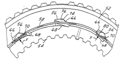
本発明の別の実施の形態が図3乃至図8に図示されている。この実施の形態は、図面において全体として参照番号50で示してある。ワンウェイラチェットクラッチ組立体50において、回転止め部材を係合位置に向けて傾動する力を提供するために、ばねが使用される。遠心力により非係合状態とされる爪にとって外側レースが静止しているときに係合しなければならない、係合する爪にとってばねが特に必要である。図3乃至図8において、組立体50は、外側レース部材52と、内側レース部材54と、複数の爪部材56と、一対のガーターばね58、60とを備えている。また、図3に図示した実施の形態おいて、一対の保持座金62、64が設けられており、これらについて更に以下に説明する。
Another embodiment of the present invention is illustrated in FIGS. This embodiment is indicated generally by the
図7により具体的に図示するように、爪部材56は、外側レース部材52の空所66内に配置され、内側レース54の切欠き68に係合し得るようにされている。一方のみを図7に図示したガーターばね58、60は、細いワイヤーコイルで出来ており且つ市販のものである。2つのガーターばね58、60を利用する図3に図示した実施の形態の場合、図8に図示するように、複数の爪部材56が利用される。該爪部材56の各々は、一対の凹所、すなわち側部溝70、72を有している。ガータばね58、60は、爪部材が外側レース内に配置されたとき、溝70、72内に配置されている。爪部材56の構造の他のものは、図1及び図2に関して上述した爪部材25と同様であり、この点に関して、爪部材は、空所66内の頂部又は凹所76に合わさる回動リッジ74を有している。
As shown more specifically in FIG. 7, the
ばね部材58、60の作動状態は、図7のばね58及び爪部材56に関連して示してある。この点に関して、爪部材がその非係合位置にあるとき、ガーターばね58は、外側レース部材に向けて、このため、爪部材の係合位置に向けた力を提供する。このばねは、爪部材の各々の表面80に力Fを作用する(図7に図示するように)。爪部材56がその係合位置にあるとき、すなわち内側レースの切欠き68と合わさっているとき、ばね部材58は弛緩しており、爪部材にばね力を付与しない。この状態は、図7の中央の爪部材56に関して示してある。
The operating state of the
また、このばね力は、爪の幾何学的形態の単一の側部溝又は中央溝に作用し得るように配置することもできる。この状態は、図9及び図10にそれぞれ図示されており、この場合、爪部材は、参照番号82、84で表示してある。ガーターばねは仮想線で且つ参照番号86で示してある。図9及び図10に図示した爪の実施の形態の何れかを図3乃至図7に図示した本発明の実施の形態と共に利用する場合、これに対応してリボンばねの位置及び提供されるリボンばねの数が調節される。
This spring force can also be arranged so that it can act on a single side or center groove of the pawl geometry. This state is illustrated in FIGS. 9 and 10, respectively, in which case the claw members are indicated by
図面(図6)の開口部すなわち穴81は、ワンウェイクラッチ組立体50が利用される伝伝動装置又はその他の機構を潤滑する注入穴を提供する。幾つかの注入穴をクラッチ組立体に形成することが好ましい。
The opening or
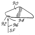
また、爪部材に対し別の方法にてばね力を付与することもできる。図11及び図12に図示するように、爪部材90は、長手方向に又は軸方向に伸長する溝92を有している。矢印96の方向に向けてばね力(SF)を提供すべく小型のリボンばね94が利用される。該リボンばね94は、ばね鋼材料で出来た細いストリップを切ったものであることが好ましく、また、爪部材90の係合位置に向けて力SFを提供し得るように溝92内に配置されることが好ましい。
Further, the spring force can be applied to the claw member by another method. As shown in FIGS. 11 and 12, the
座金62、64は、軸方向保持装置又は保持部材としても公知であり、本発明の作用を改良し又は向上させるために使用することができる。部材62、64は、爪部材をクラッチ組立体内にて軸方向に(長手方向に)保持する。また、保持部材は、内側レース及び外側レースを、相対的な自在回転を許容しつつ軸方向に整合した位置に保持する。更に、軸方向の保持部材は、クラッチ組立体に対して回転し且つ組立体を通じて軸方向負荷を支承しなければならない機構の外部部品とクラッチ組立体の間のスラスト軸受として機能する。最後に、軸方向保持部材(座金)62、64は、爪部材の過剰な磨耗を防止するために必要とされる、クラッチ組立体内の潤滑状態を保つことができる。
The
座金62、64は、プレス嵌め、かしめ、溶接又は機械的な締結法を通じて任意の従来の方法にて外側レースに接続することができる。
また、射出成形したプラスチック製のリテーナ部材を利用することもできる。かかる部材100は、図13乃至図17に図示されている。これら図面において、ワンウェイラチェットクラッチ組立体は、全体として参照番号102で示す。リテーナ部材100と共に、組立体102は、外側レース部材104と、内側レース部材106と、複数の爪部材108と、ガーターばね部材110と、第二のリテーナ部材112とを備えている。
The
An injection molded plastic retainer member can also be used. Such a
この点に関して、図13乃至図17に図示した本発明の実施の形態において、爪部材108は、図示し且つ上述した型式の任意のものとすることが出来る。更に、爪部材108は、外側レース部材の空所120内に保持されており、また、その他の図1ないし12に関して上述したのと同一の方法にて、内側レース部材の切欠き122に係合する。
In this regard, in the embodiment of the invention illustrated in FIGS. 13-17, the
リテーナ部材100は、内側レース106と外側レース104との間にてそれぞれ環状スペース内に配置される位置に設けられた複数のフランジ又は直立の円弧状の案内部材118を有している。該リテーナ部材100は、爪及びレース部材に対する半径方向軸受リテーナであり、潤滑のための潤滑油溜めとしても機能する。リテーナ部材100、112は、クラッチ組立体を共に軸方向に保持し得るように共に取り付けられることが好ましい。また、リテーナ部材は、クラッチ組立体と、該クラッチ組立体に対して回転する機構の部品との間のスラスト軸受としても機能し、該クラッチ組立体を介して軸方向負荷を支承する。リテーナ部材100、112は、プレス嵌め、かしめ、超音波溶接、機械的な締結等のような従来の任意の方法にて共に接続することができる。該リテーナ部材100は、射出成形したプラスチック材料で出来ていることが好ましく、また、規則的な鋼対鋼(steel−on−steel)の軸受にて優れた軸受機能を発揮し得るように低摩擦率を有することが好ましい。
The
本発明による別のリボンばねの実施の形態が図18及び図19に示してある。この実施の形態において、上述した爪部材90と同一の爪部材90´が利用される。該爪部材90′は、軸方向溝92′を有している。リボンばね部材130は、円環状の形状をしており、クラッチ組立体の内側レース部材と外側レース部材との間に嵌まり得るようにされている。このばね部材130は、ばね鋼で出来ていることが好ましく、各々がタブ部材134を有する複数の開口部又は窓部132(その1つのみを図示)を有している。爪部材90′は、開口部132内に配置され、タブ部材は、溝92′内に配置される。リボンばね部材130は、タブ部材134を介して、内側レース部材の切欠きと係合する位置に向けて爪部材90′に偏倚力を作用させる。また、図18に示されたタブ部材134は窓132の幅及び爪90′の幅の小さな部分しか被わないが、タブがばね部材130に設けられてもよく、そのばね部材は窓及び爪部材の全幅に亘って伸びている。
Another ribbon spring embodiment according to the present invention is shown in FIGS. In this embodiment, the
本発明の精神及び範囲に従って、爪部材を内側レースの切欠きと係合する位置に向けて偏倚させるばね機構は、多岐に亙る形態とすることができる。上述したガーターばね及びリボンばね以外に、コイルばね、板ばね等のような他のばね部材を利用することができ、これらは、本発明の範囲に属するものである。この点に関して、コイルばね機構の実施の形態が図20及び図21に図示されている。外側レース部材146の空所144に接続する凹所又は穴142内に、1つ以上のコイルばね140が配置されている。該コイルばね140は、爪部材148を内側レース部材に向けて半径方向内方に偏倚させる。
In accordance with the spirit and scope of the present invention, the spring mechanism that biases the pawl member toward a position that engages the notch of the inner race can take a wide variety of forms. In addition to the garter springs and ribbon springs described above, other spring members such as coil springs, leaf springs, and the like can be used, and these belong to the scope of the present invention. In this regard, an embodiment of a coil spring mechanism is illustrated in FIGS. One or
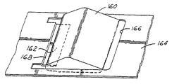
図22乃至図24に図示した本発明の実施の形態において、弾性的な偏倚部材は、爪部材の幅の全体又は実質的に全体に亙って伸長している。図22(図18、図19に図示した実施の形態に関連した図)において、爪部材160は、軸方向溝162を有している。リボン型ばね部材164は、環状の形状を有し且つクラッチ組立体の内側レース部材と外側レース部材との間に嵌まり得るようにされている。部材164は、ばね鋼で出来ており、各々がばねタブ部材168を有する複数の開口部すなわち窓部166(その1つのみ図示)を備えている。爪部材160は、開口部166内に配置され、タブ部材168は、溝162内に配置されている。ばねタブ部材168乃至リボンばね部材164は、クラッチ組立体内の爪部材160上に内側レース部材の切欠きに係合する方向に向けて偏倚力を提供する。
In the embodiment of the invention illustrated in FIGS. 22-24, the resilient biasing member extends over the entire width or substantially the entire width of the pawl member. In FIG. 22 (a diagram related to the embodiment shown in FIGS. 18 and 19), the
ばねタブ部材168は、図18、図19に図示した実施の形態にて利用されるばねタブ部材134よりも幅が広い。幅の広いばねタブ部材は、爪部材の転がり回転モードを実質的に軽減する。その結果、幅の広いばね部材は、クラッチ組立体のフリーホイール作動モード中に爪ががたつくのを防止する。幅の広いばね構造体は、転がり回転モードを拘束するのみならず、爪部材の流体減衰効果を向上させる。
The spring tab member 168 is wider than the
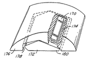
幅の広いばね部材を利用する本発明の別の実施の形態は、図23、図24に図示されている。この実施の形態において、幅の広いアコーディオン型(又は、AZ−ばね)ばね部材170は、爪部材172の半径方向外方に配置されている。ばね部材170は、爪用の空所178と接続する外側レース部材176の凹所すなわち空所174内に配置されている。ばね鋼又は同等の材料で出来たものであることが好ましいばね部材170は、爪部材172の先端180を押して、内側レース部材の切欠きに係合させる。ばね部材170の幅は、爪部材の転がり回転モードを拘束する。また、この設計により、流体及び摩擦減衰効果も得られる。ばね部材170の幅は、スペースが許容するならば、僅かにより狭くし又はより広くすることさえも可能ではあるが、爪部材の幅と実質的に等しいことが好ましい。
Another embodiment of the present invention utilizing a wide spring member is illustrated in FIGS. In this embodiment, the wide accordion-type (or AZ-spring)
本発明と共に使用することのできる別の型式のアコーディオン又はZ型ばね部材200が図25乃至図27に図示されている。ばね部材200は、ばね鋼又は同等の材料の単一片で出来ており、また、図示した方法にて切断し且つ重ね合わされている。ばね部材200と共に、重ね合わせ部分202は、接線(環状)方向(クラッチの軸方向に対して直交方向)に方向決めされ、端部の重ね合わせ部分は、クラッチのレース部材の外面又は側面に隣接して配置されている。
Another type of accordion or Z-shaped
ばね部材200は、外側レース部材206内の爪部材204を内側レース部材の切欠きと係合する方向に偏倚させるために使用される。好ましくは、ばね部材200は、爪部材204の全幅又は実質的に全体に亙って伸長するようにする。
The
幅の広い別のばね部材210が図28乃至図33Aに図示されている。ばね部材210は、ステンレス鋼(ばね焼戻しした、すなわち高降伏点の鋼)で製造され且つ図示した形状に曲げられている。ばね部材210は、ピン部材又はリベット214の周りに嵌まる逆V字形の部分212を有する一方、該リベット214は、外側レース部材215の主要な爪空所216に隣接して補助的な空所215内に固着されている。ばね部材210の平坦なフランジ部分218は、爪部材220の凹状部分222の下方に嵌まって、爪部材を内側レース部材226の切欠き224と係合するように偏倚させる。爪部材220は、爪が空所の表面に付着するのを防止するため、表面に凹部付きの湾曲溝を有している。
Another
図33Aの断面図に図示するように、ばね部材210をクラッチ組立体内にて組み立てたとき、中央部分213Cがリベット部材214に対して保持される一方、V字形部分212の外側部分213A、213Bは、補助的空所213に対して保持されている。また、好ましくは、ばね部材210をクラッチ組立体内の所定位置に保持するのに役立ち得るように一対の座金又はディスク219が設けられる。
As illustrated in the cross-sectional view of FIG. 33A, when the
図22乃至図33Aに図示した型式の幅広型式のばね部材をクラッチ組立体の色々な位置に配置し且つ従来のラチェットクラッチ、爪部材に回動リッジを有するラチェットクラッチ及び平面状ラチェットクラッチを含む、色々な型式のラチェットクラッチにて使用することができる。更に、所望であるならば、クラッチ型式の機構が利用される機械的構造体から別個の内側及び/又は外側レース部材を省き、爪用空所及び合わさる「回転止め」切欠きをロータ又は軸のような、合わさる機械的構造体の部分に直接、形成することができる。 A wide-type spring member of the type shown in FIGS. 22 to 33A is disposed at various positions of the clutch assembly, and includes a conventional ratchet clutch, a ratchet clutch having a pawl ridge on the pawl member, and a planar ratchet clutch. It can be used with various types of ratchet clutches. In addition, if desired, the separate inner and / or outer race members can be omitted from the mechanical structure where a clutch-type mechanism is utilized, and the pawl cavity and mating “non-rotation” notches can be removed from the rotor or shaft. Can be formed directly on the part of the mechanical structure that fits together.
本発明と共に使用する代替的な実施の形態が図34乃至図44に図示されている。これらの実施の形態は、コスト、製造及び組立て方法の点にて経済性を向上させ且つ性能を向上させることを可能にする。 An alternative embodiment for use with the present invention is illustrated in FIGS. These embodiments make it possible to improve economy and improve performance in terms of cost, manufacturing and assembly methods.
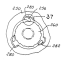
図34及び図35に図示するように、爪の空所部材はトルクコンバータ等用のステータすなわちリアクタ部材250の一部として直接、組み込まれている。部材250は、ワンウェイクラッチ機構を必要とする任意の一体の部品とすることができる。好ましくは、該部材250は、アルミニウム、プラスチック又は比較的容易に鋳造し且つ機械加工することのできるその他の材料で製造されたものとする。複数の空所部材252が部材250の内径面254に直接形成され且つ/又は機械加工されている。空所252内に配置された爪部材256は、本明細書に示し且つ記載した任意の型式とすることができ、また、質量中心CMを所定の位置に位置決めし、又は色々な型式のばね部材又は機構の1つにより係合位置に向けて付勢することができ、これらは全て本明細書に記載してある。
As shown in FIGS. 34 and 35, the claw cavity member is directly incorporated as part of a stator or
内側部材260は、その外周264の周りに配置された複数の係止切欠き262を有する上述した型式の任意の典型的な内側レース部材とすることができる。これと代替的に、典型的に、相手の歯又はスプライン部材266等により典型的に内側レース部材と合わさる中心軸部材は、軸の外面に直接機械化加工され又は形成された切欠きを有し、これにより、内側レース部材を不要にするようにしてもよい。かかる実施の形態は図39に図示されており、この場合、典型的に中空である軸部材270に複数の切欠き262´が設けられており、次に、軸部材を外側レース部材、ステータすなわちリアクタ部材等とすることのできる部材272に合わせる。軸部材270は、例えば、車の伝動装置の一部とすることができる。
クラッチの設計者の希望に従い且つ/又はクラッチ機構の作動上の仕様及びパラメータに従って任意の数の空所及び切欠きを設けることができる。図34及び図35に図示した実施の形態において、3つの空所及び爪部材が外側部材250の外周/直径部分の周りに設けられ且つ均一に隔てられている。この数の爪部材と効果的に且つ効率的に合わさるようにすると共に、クラッチ機構をバックラッシュが制限された状態で(例えば12°)所望の時点にて係止することを許容するため、内側部材には、好ましくは10個の切欠きが設けられるようにする。
Any number of voids and notches can be provided according to the desires of the clutch designer and / or according to the operating specifications and parameters of the clutch mechanism. In the embodiment illustrated in FIGS. 34 and 35, three cavities and pawl members are provided around the outer perimeter / diameter portion of the
図36乃至図38には、挿入部材280が設けられた本発明の一つの代替的な実施の形態が図示されている。挿入部材280は、鋼又はその他の硬い又は硬化した材料で製造されており、また、クラッチ機構が利用されるとき、外側ステータ、リアクタ又はその他の部材250について利用されるであろうより柔軟な材料の損傷を防止するために使用される。挿入体は押し抜き成形鋼等にて製造することができる。
36-38 illustrate one alternative embodiment of the present invention in which an
部材250の空所部材282には、その内部に挿入部材280を配置することを許容し得るようにより大きいスペースすなわち領域が付与されている。挿入部材は、空所282に圧力嵌め、据え込み又はその他の方法で恒久的に固着される。爪部材256は、図示するようにカップ付き挿入部材の内部に配置されている。
The
本発明と共に利用可能である爪部材の別の実施の形態が図40に図示されている。この実施の形態において、爪部材300は、上述した爪部材と寸法及び比率が相違している。特に、爪部材300は、半径方向により高い高さHを有している。このことは、クラッチ機構の荷重支承能力を増大させる。
Another embodiment of a pawl member that can be used with the present invention is illustrated in FIG. In this embodiment, the
上述したその他の実施の形態と同様に、爪部材300は、外側レース、ステータすなわちリアクタ等とすることができる外側部材304の空所302内に配置されている。爪部材300の質量中心CMは図示するように頂部又は回動リッジ306に対して位置決めし、外側部材304を回転させたときに爪係合力が発生するようにすることができる。同様に、内側レース、軸部材等とするこのできる内側部材312に複数の切欠き310が形成されている。
Similar to the other embodiments described above, the
また、爪部材300に対して係合方向への傾動力を付与するのを助け得るように上述した型式のばね部材又は機構及び実施の形態の1つを利用することも可能である。図40に図示したワンウエイラチェットクラッチ機構の1つ以上の側部に保持座金又はスラストベアリングを使用することも可能である。クラッチの技術にて従来から利用されているように、適当な潤滑材通路及び開口を設けることも更に可能である。
It is also possible to utilize one of the above-described types of spring members or mechanisms and embodiments so as to help impart tilting force in the engagement direction to the
一つの追加的な実施の形態として、ステータ、リアクタ又はその他の機械的部材と組み合わさった挿入体として外側部材を提供することも可能である。このことは、図41に図示されている。外側部材320は環状の形状を有し且つステータ、リアクタ又はその他の部材324のキャビティ又は凹所322内に嵌まり得るようにされている。金属材料で出来ていることが好ましい外側部材320を圧入し又はキー部材326により部材324内にキー止めすることができる。このようにして、部材324は、プラスチック材料のような低廉な材料で製造することができる。内側部材260、爪部材256等を含む、クラッチ機構の他の部分は上述したものと同一である。
As one additional embodiment, the outer member can be provided as an insert in combination with a stator, reactor or other mechanical member. This is illustrated in FIG.
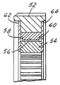
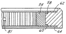
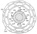
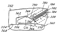
本発明の更に好ましい実施の形態が図42乃至図44に図示されており、これらは、全体として、参照番号350で示してある。この爪型式のワンウェイクラッチ機構の好ましい実施の形態は、基本的に、ステータ部材352と、内側レース部材354と、複数の爪部材356と、複数のばね部材358という4つの部分を有している。
A further preferred embodiment of the present invention is illustrated in FIGS. 42-44, which are indicated generally by the
ステータ部材352の内径部360は好ましくは極めて小さい隙間(0.025mm(0.001インチ)乃至0.127mm(0.005インチ)程度)にて内側レース部材354を受け入れ得るように機械加工されている。また、該ステータは、爪部材356を収容し得るように内径部に形成された複数の空所362も有している。爪部材及び空所は上述した爪部材及び空所と同様に形成されているが、質量中心(CM)が、爪部材が離脱方向に向けて偏倚されるようにリッジ364に対して配置される点が相違している。
The
内側レース部材354は、その外径部又は外面368に形成された複数の切欠き366を有している。これら切欠きは、爪部材に係合し且つステータ部材352が内側レース部材354に対して一方向に回転するのを防止するために使用される複数の歯370を提供し得るように形成されている。2つの部材352、354は、反対方向に回転自在すること、すなわちフライホイール回転することが許容される。内側レース部材354の内径部372は、例えば、伝動装置に固定された静止型支持軸部材374と合わさる従来のスプライン結合した形態を有する。
The
ばね部材358は、鋼のようなばね型式の金属材料を折重ねた部分から形成された板ばね部材である。この材料は、Z字形のばねの形態に折り重ねられ、ばね部材の長さ380はクラッチ機構の軸方向に配置され、ばね部材の端部折重ね部分382及び自由端部384は爪部材の軸方向長さの端部付近に配置されている。この点に関して、ばね部材358は実質的に爪部材356の全長に亙って伸長し且つ爪部材に亙って均一に係合偏倚力を提供することが好ましい。
The
ばね部材358は、ステータ部材352に形成され且つ爪空所362と交差し又は爪空所362内に開放する凹所又は空所390内に配置されている。凹所390は、ばね部材358を圧縮状態すなわち偏倚状態にて保持するのに十分な高さ「h」を有し、このため、ばねは爪部材に対し偏倚力を提供する。凹所390は、実質的に爪部材の長さに等しい長さ「L」を有する。
The
図42及び図44に図示した実施の形態において、4つの爪部材及び18の切欠きが設けられている。現在の好ましい実施の形態において、4つの爪部材及び10個の切欠きが設けられている。また、上述したように、ワンウェイクラッチ組立体の設計及びその所期の用途及び環境に対応して、他の数の爪部材及び切欠きを設けることも可能である。好ましくは、爪部材及び切欠きの配置及び位置決めは、2つの爪部材が同時に係合し、クラッチ機構の回転を防止するようにする。 In the embodiment shown in FIGS. 42 and 44, four claw members and 18 notches are provided. In the presently preferred embodiment, four pawl members and ten notches are provided. Also, as described above, other numbers of pawl members and notches can be provided depending on the design of the one-way clutch assembly and its intended use and environment. Preferably, the positioning and positioning of the pawl member and notch is such that the two pawl members engage simultaneously and prevent rotation of the clutch mechanism.
空所362は、所望に応じてフライス削り又はブローチ削り作業によりステータ部材352に機械加工することができる。また、空所は鋳造されるときにステータに形成してもよい。好ましくは、鋳造工程は、空所を最終寸法に仕上げ機械加工することが不要であるように正確な寸法及び方向を提供し得るものとする。
The void 362 can be machined into the
図42乃至図44に図示した好ましい実施の形態において、従来から公知であるように、鋼材料で出来た内側レースを提供することができる。しかしながら、外側部材は、アルミニウム又はプラスチック材料のような非鉄材料で製造されることが好ましい。これら材料は鋼よりも軽量であり且つワンウェイクラッチ機構の仕様及び必要な性能に適合するのに十分な強度及び耐久性が付与されることが好ましい。ばね部材及び爪部材は、鋼のような、現在のワンウェイクラッチ機構について使用される従来の任意の材料にて提供することができる。 In the preferred embodiment illustrated in FIGS. 42-44, an inner race made of steel material can be provided, as is known in the art. However, the outer member is preferably made of a non-ferrous material such as aluminum or a plastic material. These materials are preferably lighter than steel and are given sufficient strength and durability to meet the specifications and required performance of the one-way clutch mechanism. The spring member and pawl member can be provided in any conventional material used for current one-way clutch mechanisms, such as steel.
ステータ部材に対しアルミニウム金属材料が好ましいが、その他の非鉄金属材料を利用することもできる。これら材料は、ガスタービンエンジンのような高温のエンジンの用途にて一般に使用されるチタン、亜鉛、ニッケル及び超合金を含む。 An aluminum metal material is preferred for the stator member, but other non-ferrous metal materials can be used. These materials include titanium, zinc, nickel and superalloys commonly used in high temperature engine applications such as gas turbine engines.
ステータ部材352に対して利用することのできるプラスチック材料は、今日、高温及び高応力の用途にて使用されている任意の材料を含むことが好ましい。この材料は、高引張り強度及び撓み強度を有し、また、車又はエンジンの伝動装置にて一般に使用される液圧流体又はその他の流体の存在下にて構造上の一体性を備えるものであることを要する。
The plastic materials that can be utilized for the
熱硬化性材料及び熱可塑性材料の双方が考えられる。ポリプロピレン、ポリエチレン(高密度であることが好ましい)、ナイロン及びポリ塩化ビニル(高分子量であることが好ましい)のような重合体を適当なプラスチック材料として考えることができる。当業者は、可塑剤、熱安定剤、フィラー、潤滑剤等を重合体に添加することにより色々な設計パラメータを調節し得ることが容易に理解されよう。また、プラスチック材料は、ガラス繊維等にて強化することもできる。最後に、その開示内容を参考として引用し、本明細書に含めた、米国特許第5,121,686号に開示されるように、デュロプラスト(Duroplast)という商標名でも公知であるフェノール系樹脂プラスチックは、自動車のクラッチ組立体の製造に使用されており、また、本明細書に記載したステータ部材の製造にも適している。 Both thermosetting materials and thermoplastic materials are conceivable. Polymers such as polypropylene, polyethylene (preferably high density), nylon and polyvinyl chloride (preferably high molecular weight) can be considered as suitable plastic materials. One skilled in the art will readily appreciate that various design parameters can be adjusted by adding plasticizers, heat stabilizers, fillers, lubricants, and the like to the polymer. Further, the plastic material can be reinforced with glass fiber or the like. Finally, a phenolic resin known under the trade name Duroplast as disclosed in US Pat. No. 5,121,686, the disclosure of which is incorporated by reference. Plastic is used in the manufacture of automotive clutch assemblies and is also suitable for the manufacture of the stator members described herein.
クラッチ機構が係合することにより爪に作用する力、従って、ステータ部材にて空所の壁に加えられる力が、空所又はステータ部材を損傷させないことを確実にするため、空所の各々には、より硬い材料で出来た挿入体を提供することが可能である。このように、図36乃至図38に関して上述した型式の挿入部材を提供することができる。同様に、空所の壁は、図43に破線392で示すように、より硬い被覆又は材料にてライニングすることができる。
To ensure that the force acting on the pawl when the clutch mechanism is engaged, and thus the force applied to the cavity wall by the stator member, does not damage the cavity or the stator member. Can provide an insert made of a harder material. Thus, an insertion member of the type described above with respect to FIGS. 36-38 can be provided. Similarly, the cavity wall can be lined with a harder coating or material, as shown by dashed
非鉄のステータ部材を利用する好ましい実施の形態において、爪部材を係合方向に向けて偏倚させる機構として、すなわち、図42乃至図44に図示したZ字形の板ばね部材の一つの代替例として、他のばね機構を利用することも可能である。この目的のため、図3乃至図7に示したように、1つ以上のガーターばね部材を利用することもできる。かかるばね部材と共に、図8乃至図10に図示するように、凹所を有する対応する爪部材を利用してもよい。 In a preferred embodiment utilizing a non-ferrous stator member, as a mechanism for biasing the pawl member in the engagement direction, ie, as an alternative to the Z-shaped leaf spring member illustrated in FIGS. Other spring mechanisms can be used. For this purpose, one or more garter spring members may be utilized as shown in FIGS. Along with such a spring member, a corresponding pawl member having a recess may be utilized as shown in FIGS.
本発明を実施する最良の形態を本明細書に詳細に記載したが、本発明の分野の当業者は、特許請求の範囲に記載した本発明を実施するため、色々な代替的な設計及び実施の形態が認識されよう。特許請求の範囲及び意義内に属するこれら実施の形態及び変形例の全ては、本明細書の範囲に包含されるものである。 While the best mode for practicing the invention has been described in detail herein, those skilled in the art of the invention will recognize that various alternative designs and implementations are possible to practice the invention as set forth in the claims. Will be recognized. All of these embodiments and variations that fall within the scope and meaning of the claims are intended to be embraced within the scope of this specification.
Claims (4)
複数の空所を有し、非鉄材料で出来たステータ部材と、
複数の切欠きを有する内側レース部材と、
1つが前記空所の各々に配置された複数の爪部材と、
1つが、前記爪部材の各々を前記切欠きと係合する方向に向けて偏倚する複数のZ字形のばね部材とを備える、ワンウェイラチェットクラッチ機構。 In the one-way ratchet clutch mechanism,
A stator member having a plurality of voids and made of non-ferrous material;
An inner race member having a plurality of notches;
A plurality of claw members, one disposed in each of the voids;
A one-way ratchet clutch mechanism, wherein one includes a plurality of Z-shaped spring members that bias each of the claw members toward a direction in which the claw members are engaged with the notches.
Applications Claiming Priority (2)
| Application Number | Priority Date | Filing Date | Title |
|---|---|---|---|
| US09/033,451 US5971122A (en) | 1996-09-03 | 1998-03-02 | Ratchet one-way clutch assembly unit with wide biasing springs |
| US09/257,028 US6062362A (en) | 1996-09-03 | 1999-02-25 | Ratchet one-way clutch with stator |
Related Parent Applications (1)
| Application Number | Title | Priority Date | Filing Date |
|---|---|---|---|
| JP2000534788A Division JP2003526758A (en) | 1998-03-02 | 1999-02-26 | One-way ratchet clutch assembly |
Publications (1)
| Publication Number | Publication Date |
|---|---|
| JP2009079773A true JP2009079773A (en) | 2009-04-16 |
Family
ID=40668310
Family Applications (1)
| Application Number | Title | Priority Date | Filing Date |
|---|---|---|---|
| JP2008311102A Pending JP2009079773A (en) | 1998-03-02 | 2008-12-05 | One-way ratchet clutch assembly |
Country Status (1)
| Country | Link |
|---|---|
| JP (1) | JP2009079773A (en) |
Citations (6)
| Publication number | Priority date | Publication date | Assignee | Title |
|---|---|---|---|---|
| JPS511817B2 (en) * | 1972-09-05 | 1976-01-21 | ||
| JPS51126451A (en) * | 1974-11-06 | 1976-11-04 | Stieber & Nebelmeier Fa | Free wheel clutch |
| JPS6022210B2 (en) * | 1983-12-12 | 1985-05-31 | 株式会社日立製作所 | synchronous gear fittings |
| JPH0623579B2 (en) * | 1989-06-30 | 1994-03-30 | エヌエスケー・ワーナー株式会社 | One-way clutch |
| JPH06213258A (en) * | 1992-12-08 | 1994-08-02 | Borg Warner Automot Inc | Unidirectional roller clutch |
| WO1997041367A1 (en) * | 1996-05-01 | 1997-11-06 | Epilogics, Lp | A one-way drive device and a mechanical assembly integrating the device |
-
2008
- 2008-12-05 JP JP2008311102A patent/JP2009079773A/en active Pending
Patent Citations (7)
| Publication number | Priority date | Publication date | Assignee | Title |
|---|---|---|---|---|
| JPS511817B2 (en) * | 1972-09-05 | 1976-01-21 | ||
| JPS51126451A (en) * | 1974-11-06 | 1976-11-04 | Stieber & Nebelmeier Fa | Free wheel clutch |
| JPS6022210B2 (en) * | 1983-12-12 | 1985-05-31 | 株式会社日立製作所 | synchronous gear fittings |
| JPH0623579B2 (en) * | 1989-06-30 | 1994-03-30 | エヌエスケー・ワーナー株式会社 | One-way clutch |
| JPH06213258A (en) * | 1992-12-08 | 1994-08-02 | Borg Warner Automot Inc | Unidirectional roller clutch |
| WO1997041367A1 (en) * | 1996-05-01 | 1997-11-06 | Epilogics, Lp | A one-way drive device and a mechanical assembly integrating the device |
| JP2000500849A (en) * | 1996-05-01 | 2000-01-25 | エピロジックス リミテッド パートナーシップ | One-way drive and mechanical assembly integrating the same |
Similar Documents
| Publication | Publication Date | Title |
|---|---|---|
| JP2009109017A (en) | Ratchet one-way clutch assembly | |
| EP1862690B1 (en) | Ratchet clutch with bearing surfaces | |
| EP1265000B1 (en) | Ratchet one-way clutch assembly | |
| US6062362A (en) | Ratchet one-way clutch with stator | |
| US7383930B2 (en) | Overrunning clutch | |
| US5971122A (en) | Ratchet one-way clutch assembly unit with wide biasing springs | |
| EP1031752B1 (en) | Ratchet one-way clutch assembly with restraining members | |
| JP4267703B2 (en) | Ratchet one-way clutch assembly | |
| US5829565A (en) | One-way clutch | |
| JP2009079773A (en) | One-way ratchet clutch assembly |
Legal Events
| Date | Code | Title | Description |
|---|---|---|---|
| A131 | Notification of reasons for refusal |
Free format text: JAPANESE INTERMEDIATE CODE: A131 Effective date: 20091224 |
|
| A601 | Written request for extension of time |
Effective date: 20100323 Free format text: JAPANESE INTERMEDIATE CODE: A601 |
|
| A602 | Written permission of extension of time |
Free format text: JAPANESE INTERMEDIATE CODE: A602 Effective date: 20100326 |
|
| A601 | Written request for extension of time |
Free format text: JAPANESE INTERMEDIATE CODE: A601 Effective date: 20100423 |
|
| A602 | Written permission of extension of time |
Free format text: JAPANESE INTERMEDIATE CODE: A602 Effective date: 20100428 |
|
| A601 | Written request for extension of time |
Effective date: 20100521 Free format text: JAPANESE INTERMEDIATE CODE: A601 |
|
| A602 | Written permission of extension of time |
Effective date: 20100526 Free format text: JAPANESE INTERMEDIATE CODE: A602 |
|
| A521 | Written amendment |
Effective date: 20100604 Free format text: JAPANESE INTERMEDIATE CODE: A523 |
|
| A02 | Decision of refusal |
Effective date: 20101101 Free format text: JAPANESE INTERMEDIATE CODE: A02 |