JP2009073097A - Liquid jet apparatus, liquid container and data writing method - Google Patents
Liquid jet apparatus, liquid container and data writing method Download PDFInfo
- Publication number
- JP2009073097A JP2009073097A JP2007245502A JP2007245502A JP2009073097A JP 2009073097 A JP2009073097 A JP 2009073097A JP 2007245502 A JP2007245502 A JP 2007245502A JP 2007245502 A JP2007245502 A JP 2007245502A JP 2009073097 A JP2009073097 A JP 2009073097A
- Authority
- JP
- Japan
- Prior art keywords
- liquid
- remaining amount
- abnormality
- ejecting apparatus
- container
- Prior art date
- Legal status (The legal status is an assumption and is not a legal conclusion. Google has not performed a legal analysis and makes no representation as to the accuracy of the status listed.)
- Withdrawn
Links
Images


Classifications
-
- B—PERFORMING OPERATIONS; TRANSPORTING
- B41—PRINTING; LINING MACHINES; TYPEWRITERS; STAMPS
- B41J—TYPEWRITERS; SELECTIVE PRINTING MECHANISMS, i.e. MECHANISMS PRINTING OTHERWISE THAN FROM A FORME; CORRECTION OF TYPOGRAPHICAL ERRORS
- B41J2/00—Typewriters or selective printing mechanisms characterised by the printing or marking process for which they are designed
- B41J2/005—Typewriters or selective printing mechanisms characterised by the printing or marking process for which they are designed characterised by bringing liquid or particles selectively into contact with a printing material
- B41J2/01—Ink jet
- B41J2/17—Ink jet characterised by ink handling
- B41J2/175—Ink supply systems ; Circuit parts therefor
- B41J2/17566—Ink level or ink residue control
-
- B—PERFORMING OPERATIONS; TRANSPORTING
- B41—PRINTING; LINING MACHINES; TYPEWRITERS; STAMPS
- B41J—TYPEWRITERS; SELECTIVE PRINTING MECHANISMS, i.e. MECHANISMS PRINTING OTHERWISE THAN FROM A FORME; CORRECTION OF TYPOGRAPHICAL ERRORS
- B41J2/00—Typewriters or selective printing mechanisms characterised by the printing or marking process for which they are designed
- B41J2/005—Typewriters or selective printing mechanisms characterised by the printing or marking process for which they are designed characterised by bringing liquid or particles selectively into contact with a printing material
- B41J2/01—Ink jet
- B41J2/17—Ink jet characterised by ink handling
- B41J2/175—Ink supply systems ; Circuit parts therefor
- B41J2/17503—Ink cartridges
- B41J2/17513—Inner structure
Landscapes
- Ink Jet (AREA)
Abstract
Description
本発明は、液体収容容器に備えられた記憶装置にデータを書き込む技術に関する。 The present invention relates to a technique for writing data in a storage device provided in a liquid container.
インクジェット式記録装置やインクジェット捺染装置、マイクロディスペンサ等の液体噴射装置は、液体収容容器からインク等の液体の供給を受けてその噴射を行う。液体収容容器には、その液体収容容器の製造日や製造者、シリアル番号などが記録された不揮発性の記憶装置が備えられていることが多い。 A liquid ejecting apparatus such as an ink jet recording apparatus, an ink jet textile printing apparatus, or a micro dispenser receives a liquid such as ink from a liquid container and ejects the liquid. The liquid container is often provided with a nonvolatile storage device in which the date of manufacture, manufacturer, serial number, and the like of the liquid container are recorded.
液体噴射装置は、液体収容容器に備えられた記憶装置に対して種々の情報を記録することができる。例えば、下記特許文献1には、印刷装置に関する情報として、印刷装置のシリアル番号や、ジャムが発生した回数、印刷装置の累積稼働時間、印刷枚数等の情報が記録されると記載されている。また、下記特許文献2には、液体収容容器の使用履歴に関するデータとして、洗浄状況や、交換状況、最終使用時期等の情報が記録されると記載されている。
The liquid ejecting apparatus can record various kinds of information in the storage device provided in the liquid storage container. For example, Japanese Patent Application Laid-Open No. 2004-228561 describes that information such as a serial number of a printing apparatus, the number of times a jam has occurred, the cumulative operating time of the printing apparatus, and the number of printed sheets are recorded as information about the printing apparatus.
液体収容容器の製造者は、使用済みの液体収容容器を回収して、記憶装置に書き込まれた情報を解析することで、液体収容容器の使用状況や使用されている液体噴射装置の情報を容易に収集することが可能になる。しかし、液体収容容器の品質向上や不具合対策のために、上述した情報以外にも、他に有用な情報が記録されることが望まれていた。 The manufacturer of the liquid storage container collects the used liquid storage container and analyzes the information written in the storage device, so that the usage status of the liquid storage container and the information of the liquid ejecting apparatus being used can be easily obtained. Can be collected. However, in order to improve the quality of the liquid storage container and countermeasures against defects, it has been desired to record other useful information in addition to the information described above.
このような問題を考慮し、本発明が解決しようとする課題は、液体収容容器が備える記憶装置に有用な情報を書き込むことにある。 Considering such problems, the problem to be solved by the present invention is to write useful information in a storage device provided in the liquid container.
上記課題を踏まえ、本発明の一態様である液体噴射装置を次のように構成した。 Based on the above problems, a liquid ejecting apparatus which is one embodiment of the present invention is configured as follows.
本発明の一態様の液体噴射装置は、
データを書込可能な記憶装置と、収容されている液体の残量状態を検出する残量状態検出器とを備えた液体収容容器から前記液体の供給を受けて該液体の噴射を行う液体噴射装置であって、
前記残量状態検出器から前記液体の残量状態に関する信号を受けて、該信号を解析することにより、前記残量状態検出器に関する異常を検出する異常検出部と、
前記異常が検出された場合に、前記異常についてのデータを、前記記憶装置に書き込む書込部とを備える。
A liquid ejecting apparatus according to one embodiment of the present invention includes:
Liquid ejection that receives the supply of the liquid from a liquid storage container that includes a storage device capable of writing data and a remaining state detector that detects a remaining state of the contained liquid. A device,
An abnormality detector that receives a signal relating to the remaining amount state of the liquid from the remaining amount state detector and analyzes the signal to detect an abnormality relating to the remaining amount state detector;
And a writing unit that writes data about the abnormality to the storage device when the abnormality is detected.
上記態様の液体噴射装置によれば、液体収容容器に備えられた記憶装置に、残量状態検出器に関する異常についてのデータを書き込むことができる。そのため、使用済みの液体収容容器を回収した者は、記憶装置に記録されたデータを解析することで、液体収容容器の構成部品のうち、残量状態検出器に異常が生じる頻度や、残量状態検出器に異常が生じる時期、異常が生じやすい製造日や地域などの情報を解析することが可能になる。 According to the liquid ejecting apparatus of the above aspect, data regarding an abnormality relating to the remaining amount state detector can be written in the storage device provided in the liquid container. Therefore, a person who has collected a used liquid container can analyze the data recorded in the storage device to determine the frequency of occurrence of an abnormality in the remaining amount state detector among the components of the liquid container and the remaining amount. It becomes possible to analyze information such as the time when an abnormality occurs in the state detector and the manufacturing date and area where the abnormality is likely to occur.
上記態様の液体噴射装置は、更に、前記液体収容容器に収容されている前記液体を加圧する加圧部を備え、前記液体収容容器は、前記加圧部によって前記液体が加圧されている場合に、前記液体を前記液体噴射装置に供給するものであり、前記異常検出部は、前記残量状態検出器から受けた前記液体の残量状態に関する信号と、前記加圧部による前記液体の加圧の有無とを解析して、前記残量状態検出器に関する異常を検出することとしてもよい。 The liquid ejecting apparatus according to the above aspect further includes a pressurizing unit that pressurizes the liquid stored in the liquid storage container, and the liquid storage container has the liquid pressurized by the pressurization unit. In addition, the liquid is supplied to the liquid ejecting apparatus, and the abnormality detector includes a signal relating to the remaining amount of the liquid received from the remaining amount detector, and the application of the liquid by the pressurizing unit. The presence or absence of pressure may be analyzed to detect an abnormality related to the remaining amount detector.
このような態様であれば、加圧部による加圧の有無に応じて、精度良く、残量状態検出器に関する異常を検出することが可能になる。 With such an aspect, it is possible to detect an abnormality related to the remaining amount detector with high accuracy in accordance with the presence or absence of pressurization by the pressurizing unit.
上記態様の液体噴射装置は、更に、前記液体の噴射回数に基づいて、前記液体の消費量を推定する推定部を備え、前記異常検出部は、前記残量状態検出器から受けた前記液体の残量状態に関する信号と、前記推定された前記液体の消費量とを解析して、前記残量状態検出器に関する異常を検出することとしてもよい。 The liquid ejecting apparatus according to the above aspect further includes an estimating unit that estimates a consumption amount of the liquid based on the number of times of ejecting the liquid, and the abnormality detecting unit is configured to detect the amount of the liquid received from the remaining state detector. It is good also as detecting the abnormality regarding the said residual amount state detector by analyzing the signal regarding the residual amount state and the estimated consumption of the said liquid.
具体的には、前記残量状態検出器は、前記液体収容容器に収容されている前記液体の残量が、所定量以下になった場合に、残量が少量であることを示す少残量信号を出力するものであり、前記異常検出部は、前記推定された消費量が所定量に達していないにも関わらず、前記残量状態検出器から、前記少残量信号を受信した場合に、前記異常が生じたと判定することとしてもよい。また、前記異常検出部は、前記推定された消費量が所定量を超えたにも関わらず、前記残量状態検出器から、前記少残量信号を受信しなかった場合に、前記異常が生じたと判定することとしてもよい。 Specifically, the remaining amount state detector is a small remaining amount indicating that the remaining amount is small when the remaining amount of the liquid stored in the liquid storage container becomes a predetermined amount or less. A signal is output, and the abnormality detection unit receives the small remaining amount signal from the remaining amount state detector even though the estimated consumption amount does not reach a predetermined amount. It may be determined that the abnormality has occurred. In addition, the abnormality detection unit generates the abnormality when the estimated consumption amount exceeds a predetermined amount and does not receive the low remaining amount signal from the remaining amount state detector. It may be determined that
これらの態様であれば、液体の消費量を推定することで、精度良く、残量状態検出器に関する異常を検出することが可能になる。 If it is these aspects, it will become possible to detect the abnormality regarding a residual amount state detector accurately by estimating the consumption of a liquid.
上記態様の液体噴射装置において、前記書込部は、前記異常についてのデータに加えて、前記推定された前記液体の消費量を示すデータを、前記記憶装置に書き込むこととしてもよい。このような態様であれば、異常が生じた時点の液体の推定消費量の傾向を解析することが可能になる。 In the liquid ejecting apparatus according to the above aspect, the writing unit may write data indicating the estimated amount of consumption of the liquid in the storage device in addition to the data on the abnormality. With such an aspect, it becomes possible to analyze the tendency of the estimated consumption of liquid at the time when an abnormality occurs.
上記態様の液体噴射装置において、前記記憶装置は、前記異常についてのデータのみが書き込まれる専用領域を備えることとしてもよい。このような態様であれば、データの解析を容易に行うことが可能になる。 In the liquid ejecting apparatus according to the above aspect, the storage device may include a dedicated area in which only data regarding the abnormality is written. With such an aspect, it is possible to easily analyze data.
上記態様の液体噴射装置において、前記記憶装置には、前記液体収容容器の固体に関する固体情報が書き込まれており、前記書込部は、前記固体情報の少なくとも一部を、前記異常についてのデータに書き換えることとしてもよい。このような態様であれば、記憶装置の記憶容量を節減することが可能になる。 In the liquid ejecting apparatus according to the above aspect, solid information about the solid in the liquid container is written in the storage device, and the writing unit converts at least part of the solid information into data about the abnormality. It may be rewritten. With such an aspect, the storage capacity of the storage device can be saved.
本発明は、次のような液体収容容器としての態様としても構成することが可能である。 The present invention can also be configured as the following liquid container.
本発明の一態様である液体収容容器は、
液体噴射装置に供給される液体を収容する液体収容容器であって、
該液体収容容器に収容されている前記液体の残量状態を検出し、前記液体噴射装置に対して前記液体の残量状態に関する信号を出力する残量状態検出器と、
前記液体噴射装置によって、前記液体の残量状態に関する信号が解析されることにより、前記残量状態検出器に関する異常が検出された場合に、該異常についてのデータが前記液体噴射装置によって書き込まれる記憶領域を有する記憶装置とを備える。
The liquid storage container which is one embodiment of the present invention,
A liquid storage container for storing a liquid to be supplied to a liquid ejecting apparatus,
A remaining amount state detector that detects a remaining amount state of the liquid stored in the liquid container and outputs a signal related to the remaining amount state of the liquid to the liquid ejecting apparatus;
A memory in which data relating to the abnormality is written by the liquid ejecting device when an abnormality relating to the remaining amount state detector is detected by analyzing a signal relating to the remaining state of the liquid by the liquid ejecting device. And a storage device having a region.
上記態様の液体収容容器の記憶装置には、残量状態検出器に関する異常についてのデータが書き込まれる。そのため、使用済みの液体収容容器を回収した者は、液体収容容器の構成部品のうち、残量状態検出器に異常が生じる頻度や、残量状態検出器に異常が生じる時期、異常が生じやすい製造日や地域などの情報を解析することが可能になる。 In the storage device of the liquid container of the above aspect, data on abnormality relating to the remaining amount state detector is written. Therefore, a person who has collected a used liquid storage container is likely to have an abnormality in the frequency of occurrence of an abnormality in the remaining amount state detector or an abnormality in the remaining state detector among the components of the liquid storage container. It becomes possible to analyze information such as the date of manufacture and region.
なお、本発明は、上述した液体噴射装置や液体収容容器としての構成のほか、液体噴射装置によるデータ書込方法や、データを書き込むためのコンピュータプログラムとしても構成することができる。かかるコンピュータプログラムは、コンピュータが読取可能な記録媒体に記録されていてもよい。記録媒体としては、例えば、フレキシブルディスクやCD−ROM、DVD−ROM、光磁気ディスク、メモリカード、ハードディスク等の種々の媒体を利用することができる。 In addition to the configuration as the liquid ejecting apparatus and the liquid container described above, the present invention can also be configured as a data writing method by the liquid ejecting apparatus and a computer program for writing data. Such a computer program may be recorded on a computer-readable recording medium. As the recording medium, for example, various media such as a flexible disk, a CD-ROM, a DVD-ROM, a magneto-optical disk, a memory card, and a hard disk can be used.
以下、本発明の実施の形態を実施例に基づき次の順序で説明する。
A.第1実施例:
(A1)液体噴射装置の構成:
(A2)液体収容容器の構成:
(A3)異常判定処理:
B.第2実施例:
C.変形例:
Hereinafter, embodiments of the present invention will be described in the following order based on examples.
A. First embodiment:
(A1) Configuration of liquid ejecting apparatus:
(A2) Configuration of liquid container:
(A3) Abnormality determination processing:
B. Second embodiment:
C. Variations:
A.第1実施例:
(A1)液体噴射装置の構成:
図1は、液体噴射装置20の概略構成を示す説明図である。本実施例の液体噴射装置20は、記録ヘッド21から記録用紙にインクを吐出(噴射)して画像や文字を印刷するインクジェット式の記録装置である。この液体噴射装置20には、インクが収容された液体収容容器10が装着される。液体収容容器10は、液体噴射装置20の記録ヘッド21に対してインクの供給を行う着脱自在なカートリッジ式の容器である。
A. First embodiment:
(A1) Configuration of liquid ejecting apparatus:
FIG. 1 is an explanatory diagram showing a schematic configuration of the
図1に示すように、液体噴射装置20は、空気を加圧する加圧ポンプ23と、加圧された空気を液体収容容器10に供給する空気流路24とを備えている。また、液体噴射装置20は、液体収容容器10から供給されたインクを記録ヘッド21に導くインク流路25と、インクを記録媒体に吐出する記録ヘッド21とを備えている。更に、液体噴射装置20は、記録ヘッド21を制御して印刷を行う印刷処理や、後述する異常判定処理を実行する制御回路22を備えている。
As shown in FIG. 1, the liquid ejecting
加圧ポンプ23によって加圧された空気は、空気流路24を通って液体収容容器10に供給される。空気流路24には、圧力センサ26と大気開放弁27とが備えられている。圧力センサ26と大気開放弁27とは、制御回路22に接続されている。制御回路22は、圧力センサ26によって空気流路24内の空気の圧力を検出し、その圧力に応じて、加圧ポンプ23のフィードバック制御を行う。
The air pressurized by the pressurizing
液体収容容器10から供給されたインクは、インク流路25を通って記録ヘッド21に導かれる。インク流路25には、開閉弁28が備えられている。開閉弁28は、例えば、液体噴射装置20の電源がオフにされる場合や、液体収容容器10が液体噴射装置20から取り外される場合に制御回路22によって閉弁される。なお、開閉弁28として、逆止弁を採用することが可能である。
The ink supplied from the
制御回路22は、CPUとROMとRAMとを備えている。CPUは、ROMに記録された制御プログラムをRAMにロードして実行することで、図示する異常判定部64や書込部66として機能する。異常判定部64は、液体収容容器10から出力された信号等を解析して、後述する異常判定処理を実現する機能を有する。書込部66は、インタフェース基板7を介して、液体収容容器10に搭載されたEEPROM8にデータを書き込む機能を有する。
The
(A2)液体収容容器の構成:
図1に示すように、液体収容容器10は、インクを収容する液体収容室2と、液体収容室2に収容されたインクの残量状態を検出する残量検出器3と、液体収容容器10に関する種々の情報が記録されたEEPROM8と、液体収容容器10と液体噴射装置20との電気的な接続を行うインタフェース基板7とを備えている。
(A2) Configuration of liquid container:
As shown in FIG. 1, the
液体収容容器10の筐体には、空気流入口9とインク供給口11とが備えられている。空気流入口9は、液体収容室2に連通しており、インク供給口11は、残量検出器3に連通している。液体収容容器10が液体噴射装置20に装着されると、空気流入口9は、液体噴射装置20内の加圧ポンプ23に接続され、インク供給口11は、液体噴射装置20内の記録ヘッド21に接続される。
The casing of the
液体収容室2は、空気流入口9から加圧空気が流入する加圧室5内にインクの充填された可撓性のインクパック4を設けることで構成されている。インクパック4は、可撓性を有する樹脂フィルム層の上にアルミニウム層が積層形成されたアルミラミネートフィルムを2枚用意し、これらの周縁部を互いに貼り合わせることにより形成されている。インクパック4の一端は、残量検出器3を介してインク供給口11に連通している。
The
液体噴射装置20から空気流入口9を介して加圧室5に加圧空気が流入すると、その圧力によって、インクパック4が圧せられる。すると、インクパック4内からインクが押し出され、残量検出器3およびインク供給口11を通って液体噴射装置20の記録ヘッド21にインクが供給される。
When pressurized air flows into the pressurizing
残量検出器3とEEPROM8とは、インタフェース基板7に電気的に接続されている。液体収容容器10が液体噴射装置20に装着されると、このインタフェース基板7を介して、残量検出器3とEEPROM8とが液体噴射装置20内の制御回路22に電気的に接続される。なお、インタフェース基板7は、例えば、無線通信回路を備え、これにより、制御回路22と無線による通信を行うものとしてもよい。
The remaining
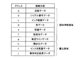
図2は、EEPROM8に記録された情報を示す説明図である。EEPROM8は、不揮発性の半導体メモリであり、液体収容容器10の個体に関する情報が記録されている個体情報領域と、液体噴射装置20の制御回路22によって種々のデータが書き込まれる書込領域とを備えている。
FIG. 2 is an explanatory diagram showing information recorded in the
個体情報領域には、例えば、(a)液体収容容器10の型番を示す型番データ、(b)液体収容容器10のシリアル番号を示すシリアル番号データ、(c)顔料系あるいは染料系といったインクの種類を示すインク種類データ、(d)収容されているインクの色を示す色データ、(e)充填されたインクの量を示す容量データ、(f)液体収容容器10の製造年月日を示す製造日データ、(g)液体収容容器10が製造された設備を示す製造ラインデータが記録されている。
In the individual information area, for example, (a) model number data indicating the model number of the
一方、書込領域には、例えば、(h)液体収容容器10が開封された年月日を示す開封日データ、(i)インクの消費量を示すインク消費量データ、(j)後述する異常判定処理の結果を示す異常判定結果データ、が記録される。液体噴射装置20は、EEPROM8に記録されたこれらのデータを読み込むことで、種々の制御を行うことができる。なお、本実施例の液体収容容器10は、不揮発性の記憶装置としてEEPROM8を備えることとしたが、フラッシュメモリやバッテリバックアップされた揮発性のメモリ、磁気的あるいは光学的に情報が記録される記憶装置を備えることとしてもよい。
On the other hand, in the writing area, for example, (h) opening date data indicating the date when the
図3は、残量検出器3の詳細な構成を示す断面図である。図示するように、残量検出器3は、内部に凹空間が形成された検出部ケース19と、凹空間の開口部を封止する可撓性フィルム17とを備えている。可撓性フィルム17と凹空間とによって形成された空間のことを、以下、センサ室18という。センサ室18の底部には、センサ室18内に流入したインクの圧力を検出するための圧力検出機構15が備えられている。可撓性フィルム17の中央部には、圧力検出機構15と対向するように受圧板16が固着されている。受圧板16および可撓性フィルム17は、コイルばね29によってセンサ室18の容積が縮小する方向に付勢されている。
FIG. 3 is a cross-sectional view showing a detailed configuration of the remaining
検出部ケース19の側壁には、液体収容室2内のインクパック4に連通するインク流入路13と、インク供給口11とが対向して設けられている。インクパック4が接続されるインク流入路13には、インクがインクパック4内に逆流することを防止する逆止弁37が設けられている。また、図示していないが、インク供給口11には、液体収容容器10が液体噴射装置20に装着された際に、液体噴射装置20に備えられたインク供給針が挿入されることにより流路が開く弁機構が備えられている。
In the side wall of the
圧力検出機構15は、受圧板16が当接可能な底板31と、底板31をU字状に貫通するインク誘導路33と、インタフェース基板7を介して液体噴射装置20の制御回路22に電気的に接続される圧電型センサ35とから構成される。
The
液体噴射装置20から供給された加圧空気が加圧室5に流入すると、インクパック4が圧せられてセンサ室18にインクが流入する。すると、このインクの圧力によって、可撓性フィルム17が上方に膨出変形する。この可撓性フィルム17の変形により、受圧板16が上方に移動して、底板31から離間する。すると、インク誘導路33がセンサ室18に連通する。この状態で、液体噴射装置20の制御回路22がインタフェース基板7を介して圧電型センサ35に所定の駆動信号を印加すると、圧電型センサ35は、アクチュエータとして所定時間励起された後に、圧電型センサ35の振動板が自由振動を開始する。こうして振動板が自由振動すると、圧電型センサ35には逆起電力が発生することになる。そうすると、この逆起電力を表す波形が出力信号として、インタフェース基板7を通じ、制御回路22に送信される。つまり、制御回路22が、圧電型センサ35に所定の駆動信号を印加することにより、圧電型センサ35から所定の波形の信号が出力された場合には、制御回路22は、液体収容容器10から「インク有り」を表す信号(以下、「インク有り信号」という)が出力されたと判断することができる。
When the pressurized air supplied from the
一方、インクパック4内に残存するインクの量が少なくなると、インクパック4が加圧されても、インクパック4からセンサ室18に流入するインクの量が減り、センサ室18内の圧力が低い状態となる。そうすると、受圧板16が底板31に当接し、インク誘導路33が閉塞される。このような状況において、制御回路22が圧電型センサ35に所定の駆動信号を供給しても、インク誘導路33内は殆ど振動せず、変動の少ない波形が出力されることになる。つまり、出力信号として、変動の少ない波形が出力された場合には、制御回路22は、液体収容容器10から「インク無し」を表す信号(以下、「インク無し信号」という)が出力されたと判断することができる。なお、「インク無し」とは、インクパック4内のインクの残量が所定量以下の状態になったことをいい、インクの残量が厳密にゼロになった状態を表すわけではない。この「所定量」は、コイルばね29のバネ力を調整することで、適宜変更することが可能である。以下の説明では、「インク有り信号」と「インク無し信号」とを、まとめて、「残量信号」という。
On the other hand, when the amount of ink remaining in the ink pack 4 decreases, the amount of ink flowing from the ink pack 4 into the
図4は、加圧ポンプ23の駆動状態に応じて液体収容容器10から出力される残量信号の類型を示す表である。図示するように、液体噴射装置20の加圧ポンプ23が停止されている場合には、液体収容容器10は、インクパック4内のインクの有無に関わらず、インク無し信号を出力する。加圧空気が供給されない場合には、インクパック4から残量検出器3にインクが流入しないからである。これに対し、加圧ポンプ23が作動している状態で、インクパック4内にインクが所定量以上残存していれば、インク有り信号が出力される。また、加圧ポンプ23が作動している状態で、インクの残量が所定量未満であれば、インク無し信号が出力される。液体噴射装置20の制御回路22は、液体収容容器10から出力された残量信号と、図4に示す残量信号の類型とを対比することで、液体収容容器10に異常が生じているかを判定することが可能になる。
FIG. 4 is a table showing types of remaining amount signals output from the
(A3)異常判定処理:
図5は、液体噴射装置20の制御回路22が実行する異常判定処理のフローチャートである。この異常判定処理は、例えば、液体収容容器10が液体噴射装置20に装着された状態で、液体噴射装置20の電源が投入された際に実行される。
(A3) Abnormality determination processing:
FIG. 5 is a flowchart of the abnormality determination process executed by the
この異常判定処理が実行されると、制御回路22は、まず、加圧ポンプ23を停止状態にする(ステップS10)。そして、液体収容容器10の残量検出器3に対して所定の駆動信号を印加することで、残量検出器3から残量信号を受信する(ステップS20)。
When this abnormality determination process is executed, the
制御回路22は、残量信号を受信すると、その信号が、インク有り信号であるかを判断する(ステップS30)。インク有り信号を受信した場合には(ステップS30:Yes)、加圧ポンプ23を停止しているにもかかわらず、インク有り信号が出力されたと解析される。このような解析結果は、受信した残量信号の態様が、図4に示した類型と異なることになる。従って、制御回路22は、液体収容容器10の残量検出器3に異常が生じたと判定する(ステップS40)。そして、異常が生じた旨を示すエラーを制御回路22が備える表示装置に表示する(ステップS50)。
When receiving the remaining amount signal, the
制御回路22が、液体収容容器10から受信した残量信号が、インク無し信号である場合には(ステップS30:No)、制御回路22は、残量検出器3から受信した信号は、正常であると判定し(ステップS60)、加圧ポンプ23の駆動を開始する(ステップS70)。
When the remaining amount signal received from the
最後に、制御回路22は、上記ステップS40もしくはステップS60による異常判定結果を書込部66の機能によって、液体収容容器10に搭載されたEEPROM8に異常判定結果データとして書き込む(ステップS80)。
Finally, the
以上で説明した第1実施例の液体噴射装置20によれば、加圧ポンプ23の駆動状態と、液体収容容器10から出力される残量信号とを解析することにより、液体収容容器10の残量検出器3に異常が生じているかを判定することができる。そして、その判定結果は、液体収容容器10に搭載されたEEPROM8に書き込まれる。従って、液体収容容器10の製造者は、使用済みの液体収容容器10を回収し、EEPROM8に書き込まれたデータを解析することで、残量検出器3に異常が生じる頻度や、異常が生じやすい製造時期、製造ライン、インクの種類、色などの情報を得ることが可能になる。
According to the
なお、上記異常判定処理のステップS70によって加圧ポンプ23を駆動した後には、インクの有無を判定する処理を行うこととしてもよい。具体的には、加圧ポンプ23を駆動させた状態で、残量検出器3に対して駆動信号を印加することにより、残量信号を受信する。そして、受信した信号を図4に基づいて解析し、受信した信号が、インク無し信号であれば、インクが残存していない旨および液体収容容器10の交換を促す旨を液体噴射装置20が備える所定の表示装置に表示する。一方、インク有り信号であれば、制御回路22によって、印刷処理等が実行可能になる。
Note that after the
B.第2実施例:
上述した第1実施例では、液体噴射装置20の電源投入時に実行される異常判定処理について説明した。これに対して、第2実施例では、印刷処理に伴って実行される異常判定処理について説明する。
B. Second embodiment:
In the first embodiment described above, the abnormality determination process executed when the
本実施例の液体噴射装置20は、図1に破線で示した残量推定部65を備えている。残量推定部65は、記録ヘッド21から吐出したインク滴の数をカウントし、そのカウント数と、インク1滴当たりのインク消費量(例えば、2ピコリットル)を乗ずることで、消費したインクの量を推定する機能を有する。残量推定部65は、印刷処理中に吐出されたインク滴の数をカウントし、その値をRAM63に記憶する機能を有している。
The
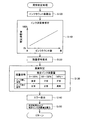
図6は、第2実施例において実行される異常判定処理のフローチャートである。本実施例の異常判定処理は、液体噴射装置20による印刷処理が完了するたびに実行される。
FIG. 6 is a flowchart of the abnormality determination process executed in the second embodiment. The abnormality determination process of the present embodiment is executed every time the printing process by the
この異常判定処理が実行されると、制御回路22は、まず、前回の印刷処理時に吐出されたインク滴のカウント数をRAM63から読み込む(ステップS100)。そして、読み込んだカウント数をこれまでカウントした総カウント数に加算して、液体収容容器10が交換された後のインクの累積消費量を推定する(ステップS110)。図中に示すように、インクの累積消費量は、カウント数が増加するにつれ、線形的に増加することになる。
When this abnormality determination process is executed, the
図中には、推定消費量をパーセンテージで示している。液体収容容器10が備えるEEPROM8には、個体情報領域内に、液体収容容器10に充填されたインクの量が容量データとして記録されている。そのため、残量推定部65は、この容量データを読み込むことで、最大インク量に対する累積消費量の割合を求めることができる。推定消費量が100%を超えるスケールまで示してあるのは、記録ヘッド21から吐出されるインク滴の大きさや、インクパック4に収容されたインクの初期量に個体差があるためである。また、例えば、残量推定部65でのカウントに使用されるインク1滴当たりのインク消費量は、記録ヘッド21から吐出されるインク量のばらつきを考慮し、想定される最も多い量に設定されている。そのため、残量検出器3によってインク無しと検出される時点での推定消費量が100%以上になる可能性があるためである。
In the figure, the estimated consumption is shown as a percentage. In the
続いて、制御回路22は、液体収容容器10の残量検出器3に対して所定の駆動信号を印加することで、液体収容容器10の残量検出器3から残量信号を受信する(ステップS120)。残量信号を受信すると、制御回路22は、ステップS110で推定した累積消費量と、ステップS120で受信した残量信号とを比較解析して、液体収容容器10に異常が生じているかを判定する(ステップS130)。
Subsequently, the
具体的には、推定されたインクの累積消費量が100%未満であるにも関わらず、インク無し信号を受信した場合には、制御回路22は、残量検出器3に異常が生じていると判定する。推定されたインクの累積消費量が0〜100%未満であれば、例えば、前述の残量推定部65でのカウントに使用されるインク1滴当たりのインク消費量の設定方法からもわかるように、インクパック4内にインクが残存しているはずであり、本来はインク有り信号が出力されるはずだからである。
Specifically, the
また、推定されたインクの累積消費量が150%以上であるにも関わらず、インク有り信号を受信した場合にも、制御回路22は、残量検出器3に異常が生じていると判定する。推定された累積消費量が150%を超えれば、記録ヘッド21によって吐出されるインクのサイズやインクパック4の容積の個体差を考慮しても、インクパック4内のインクは所定量以下になっているはずであり、インク無し信号が出力されるはずだからである。
Further, even when the estimated cumulative ink consumption is 150% or more and the ink presence signal is received, the
これらに対して、推定されたインクの累積消費量が100%以上であり、かつ、インク無し信号を受信した場合、および、推定されたインクの累積消費量が150%未満であり、かつ、インク有り信号を受信した場合には、制御回路22は、残量検出器3に異常は生じていないと(正常であると)判定する。
On the other hand, when the estimated cumulative ink consumption is 100% or more and a no-ink signal is received, the estimated cumulative ink consumption is less than 150%, and the ink When the presence signal is received, the
制御回路22は、上記ステップS130において、異常が生じたと判定した場合には、液体噴射装置20に備えられた表示装置に、異常が生じた旨を示すエラーを表示する(ステップS140)。そして、ステップS130によって判定した結果を、液体収容容器10に搭載されたEEPROM8の書込領域に異常判定結果データとして書き込む(ステップS140)。このとき、制御回路22は、同時に、インクの推定消費量についても異常判定結果データとしてEEPROM8に書き込む。
If it is determined in step S130 that an abnormality has occurred, the
以上で説明した第2実施例の液体噴射装置20によれば、推定されたインクの消費量と、残量検出器3によって検出したインクの残量状態とを比較して解析することにより、液体収容容器10の残量検出器3に異常が生じているかを判定することができる。そして、その判定結果は、インクの推定消費量とともに液体収容容器10に搭載されたEEPROM8に書き込まれる。従って、液体収容容器10の製造者は、使用済みの液体収容容器10を回収し、EEPROM8に書き込まれたデータを解析することで、残量検出器3に異常が生じる頻度や、異常が生じる場合のインクの推定消費量、異常が生じやすい製造時期、製造ライン、インクの種類、色などの情報を得ることが可能になる。
According to the
なお、上述の第2実施例で説明した異常判定処理は、第1実施例の異常判定処理と実行されるタイミングが異なる。そのため、これらの処理は、組み合わせて実行することが可能である。 It should be noted that the abnormality determination process described in the second embodiment is executed at a different timing from the abnormality determination process of the first embodiment. Therefore, these processes can be executed in combination.
C.変形例:
以上、本発明の種々の実施例について説明したが、本発明はこのような実施例に限定されず、その趣旨を逸脱しない範囲で種々の構成を採ることができることはいうまでもない。例えば、以下のような変形が可能である。
C. Variations:
Although various embodiments of the present invention have been described above, the present invention is not limited to such embodiments, and it goes without saying that various configurations can be adopted without departing from the spirit of the present invention. For example, the following modifications are possible.
(変形例1):
上記実施例では、EEPROM8内に、異常判定結果データが書き込まれる専用の領域が予め確保されていることとした。これに対して、制御回路22は、EEPROM8内に既に書き込まれている情報を、異常判定結果データに書き換えることとしてもよい。書き換えられるデータは、使用済みの液体収容容器10の解析時に重要度が低いデータとすることができる。例えば、図2に示したデータのうち、型番データ、インク種類データ、色データ、製造日データは、液体収容容器10に付されたラベル等によって確認できることが多いため、上書きの対象とすることが可能である。
(Modification 1):
In the above embodiment, a dedicated area in which the abnormality determination result data is written is reserved in the
(変形例2):
上記実施例では、残量検出器3が正常であると判定された場合においても、EEPROM8にその旨を示すデータを書き込むこととした。これに対して、EEPROM8には、初期値として、「正常」である旨のデータが記録されていることとし、異常が生じた場合にのみ、異常判定結果を書き込むこととしてもよい。
(Modification 2):
In the above embodiment, even when it is determined that the remaining
(変形例3):
上記実施例では、加圧ポンプ23の駆動状態やインクの推定消費量を考慮して、残量検出器3の異常を検出することとした。これに対して、例えば、残量検出器3とインタフェース基板7との間の配線が短絡するなどして、制御回路22が、残量検出器3に対して、所定の駆動信号を送信することが不能であった場合や、残量検出器3から何ら反応がなかった場合、あるいは、残量検出器3から異常な波形や電圧が検出された場合に、残量状態検出器3に異常が生じていると判断することも可能である。
(Modification 3):
In the above embodiment, the abnormality of the remaining
(変形例4):
上述した実施例では、液体噴射装置20はインクジェット式の記録装置であるものとした。これに対して、液体噴射装置20は、他の態様とすることが可能である。例えば、液晶ディスプレー等のカラーフィルタ製造に用いられる色材噴射ヘッドを備えた装置や、有機ELディスプレー、面発光ディスプレー(FED)等の電極形成に用いられる電極材(導電ペースト)噴射ヘッドを備えた装置、バイオチップ製造に用いられる生体有機物噴射ヘッドを備えた装置、精密ピペットとしての試料噴射ヘッドを備えた装置、捺染装置やマイクロディスペンサ等の装置を液体噴射装置として適用することが可能である。
(Modification 4):
In the embodiment described above, the
2…液体収容室
3…残量検出器
4…インクパック
5…加圧室
7…インタフェース基板
8…EEPROM
9…空気流入口
10…液体収容容器
11…インク供給口
13…インク流入路
15…圧力検出機構
16…受圧板
17…可撓性フィルム
18…センサ室
19…検出部ケース
20…液体噴射装置
21…記録ヘッド
22…制御回路
23…加圧ポンプ
24…空気流路
25…インク流路
26…圧力センサ
27…大気開放弁
28…開閉弁
29…コイルばね
31…底板
33…インク誘導路
35…圧電型センサ
37…逆止弁
64…異常判定部
65…残量推定部
66…書込部
2 ...
DESCRIPTION OF
Claims (13)
前記残量状態検出器から前記液体の残量状態に関する信号を受けて、該信号を解析することにより、前記残量状態検出器に関する異常を検出する異常検出部と、
前記異常が検出された場合に、前記異常についてのデータを、前記記憶装置に書き込む書込部と
を備える液体噴射装置。 Liquid ejection that receives the supply of the liquid from a liquid storage container that includes a storage device capable of writing data and a remaining state detector that detects a remaining state of the contained liquid. A device,
An abnormality detector that receives a signal relating to the remaining amount state of the liquid from the remaining amount state detector and analyzes the signal to detect an abnormality relating to the remaining amount state detector;
A liquid ejecting apparatus comprising: a writing unit that writes data regarding the abnormality to the storage device when the abnormality is detected.
更に、前記液体収容容器に収容されている前記液体を加圧する加圧部を備え、
前記液体収容容器は、前記加圧部によって前記液体が加圧されている場合に、前記液体を前記液体噴射装置に供給するものであり、
前記異常検出部は、前記残量状態検出器から受けた前記液体の残量状態に関する信号と、前記加圧部による前記液体の加圧の有無とを解析して、前記残量状態検出器に関する異常を検出する
液体噴射装置。 The liquid ejecting apparatus according to claim 1,
Furthermore, a pressurizing unit that pressurizes the liquid stored in the liquid container,
The liquid container is configured to supply the liquid to the liquid ejecting apparatus when the liquid is pressurized by the pressurizing unit;
The abnormality detection unit analyzes the signal regarding the remaining amount state of the liquid received from the remaining amount state detector and the presence or absence of pressurization of the liquid by the pressurizing unit, and relates to the remaining amount state detector. Liquid ejector that detects abnormalities.
更に、前記液体の噴射回数に基づいて、前記液体の消費量を推定する推定部を備え、
前記異常検出部は、前記残量状態検出器から受けた前記液体の残量状態に関する信号と、前記推定された前記液体の消費量とを解析して、前記残量状態検出器に関する異常を検出する
液体噴射装置。 The liquid ejecting apparatus according to claim 1,
Furthermore, an estimation unit that estimates the consumption amount of the liquid based on the number of times of ejection of the liquid,
The abnormality detection unit detects an abnormality related to the remaining amount state detector by analyzing a signal related to the remaining amount state of the liquid received from the remaining amount state detector and the estimated consumption amount of the liquid. Liquid ejector.
前記残量状態検出器は、前記液体収容容器に収容されている前記液体の残量が、所定量以下になった場合に、残量が少量であることを示す少残量信号を出力するものであり、
前記異常検出部は、前記推定された消費量が所定量に達していないにも関わらず、前記残量状態検出器から、前記少残量信号を受信した場合に、前記異常が生じたと判定する
液体噴射装置。 The liquid ejecting apparatus according to claim 3,
The remaining amount state detector outputs a small remaining amount signal indicating that the remaining amount is small when the remaining amount of the liquid stored in the liquid storage container becomes a predetermined amount or less. And
The abnormality detection unit determines that the abnormality has occurred when the low remaining amount signal is received from the remaining amount state detector even though the estimated consumption amount has not reached a predetermined amount. Liquid ejector.
前記残量状態検出器は、前記液体収容容器に収容されている前記液体の残量が、所定量以下になった場合に、残量が少量であることを示す少残量信号を出力するものであり、
前記異常検出部は、前記推定された消費量が所定量を超えたにも関わらず、前記残量状態検出器から、前記少残量信号を受信しなかった場合に、前記異常が生じたと判定する
液体噴射装置。 The liquid ejecting apparatus according to claim 3,
The remaining amount state detector outputs a small remaining amount signal indicating that the remaining amount is small when the remaining amount of the liquid stored in the liquid storage container becomes a predetermined amount or less. And
The abnormality detection unit determines that the abnormality has occurred when the estimated consumption amount has not exceeded the predetermined amount, but has not received the low remaining amount signal from the remaining amount state detector. Liquid ejector.
前記書込部は、前記異常についてのデータに加えて、前記推定された前記液体の消費量を示すデータを、前記記憶装置に書き込む
液体噴射装置。 A liquid ejecting apparatus according to any one of claims 3 to 5,
The writing unit writes data indicating the estimated amount of consumption of the liquid in the storage device in addition to data on the abnormality.
前記記憶装置は、前記異常についてのデータのみが書き込まれる専用領域を備える
液体噴射装置。 The liquid ejecting apparatus according to any one of claims 1 to 6,
The storage device includes a dedicated area in which only data regarding the abnormality is written.
前記記憶装置には、前記液体収容容器の固体に関する固体情報が書き込まれており、
前記書込部は、前記固体情報の少なくとも一部を、前記異常についてのデータに書き換える
液体噴射装置。 The liquid ejecting apparatus according to any one of claims 1 to 6,
Solid information about the solid of the liquid container is written in the storage device,
The writing unit rewrites at least a part of the solid information into data on the abnormality.
該液体収容容器に収容されている前記液体の残量状態を検出し、前記液体噴射装置に対して前記液体の残量状態に関する信号を出力する残量状態検出器と、
前記液体噴射装置によって、前記液体の残量状態に関する信号が解析されることにより、前記残量状態検出器に関する異常が検出された場合に、該異常についてのデータが前記液体噴射装置によって書き込まれる記憶領域を有する記憶装置と
を備える液体収容容器。 A liquid storage container for storing a liquid to be supplied to a liquid ejecting apparatus,
A remaining amount state detector that detects a remaining amount state of the liquid stored in the liquid container and outputs a signal related to the remaining amount state of the liquid to the liquid ejecting apparatus;
A memory in which data relating to the abnormality is written by the liquid ejecting device when an abnormality relating to the remaining amount state detector is detected by analyzing a signal relating to the remaining state of the liquid by the liquid ejecting device. A liquid container including a storage device having a region.
前記記憶装置は、前記異常についてのデータのみが書き込まれる専用領域を備える
液体収容容器。 The liquid container according to claim 9, wherein
The storage device includes a dedicated area in which only data on the abnormality is written.
前記記憶装置には、前記液体収容容器の固体に関する固体情報が書き込まれており、
前記記憶装置は、前記液体噴射装置によって、前記固体情報の少なくとも一部を、前記異常についてのデータに書き換えられる
液体収容容器。 The liquid container according to claim 9, wherein
Solid information about the solid of the liquid container is written in the storage device,
In the storage device, at least a part of the solid information is rewritten into data about the abnormality by the liquid ejecting apparatus.
前記残量状態検出器から前記液体の残量状態に関する信号を受けて、該信号を解析することにより、前記残量状態検出器に関する異常を検出する異常検出部と、
前記異常が検出された場合に、前記異常についてのデータを、前記記憶装置に書き込む書込部と、
前記液体収容容器から供給された液体を噴射する噴射部と
を備える液体噴射装置。 A liquid container according to any one of claims 9 to 11,
An abnormality detector that receives a signal relating to the remaining amount state of the liquid from the remaining amount state detector and analyzes the signal to detect an abnormality relating to the remaining amount state detector;
A writing unit that writes data about the abnormality to the storage device when the abnormality is detected;
A liquid ejecting apparatus comprising: an ejecting unit that ejects the liquid supplied from the liquid container.
前記液体収容容器に備えられた残量状態検出器を用いて、該液体収容容器に収容されている前記液体の残量状態を検出し、
前記検出された前記液体の残量状態を解析して、前記残量状態検出器に関する異常を検出し、
前記異常が検出された場合に、該異常についてのデータを、前記液体収容容器に備えられた前記記憶装置に書き込む
データ書込方法。 A liquid writing apparatus that ejects the liquid by receiving a supply of liquid from a liquid storage container including a storage device is a data writing method for writing data to the storage device,
Using a remaining amount detector provided in the liquid container, the remaining amount state of the liquid stored in the liquid container is detected,
Analyzing the remaining state of the detected liquid to detect an abnormality related to the remaining state detector,
A data writing method for writing data about an abnormality to the storage device provided in the liquid container when the abnormality is detected.
Priority Applications (3)
| Application Number | Priority Date | Filing Date | Title |
|---|---|---|---|
| JP2007245502A JP2009073097A (en) | 2007-09-21 | 2007-09-21 | Liquid jet apparatus, liquid container and data writing method |
| US12/233,058 US8061799B2 (en) | 2007-09-21 | 2008-09-18 | Liquid ejecting apparatus, liquid container, and data writing method |
| CN2008102114213A CN101417542B (en) | 2007-09-21 | 2008-09-22 | Liquid ejecting apparatus, liquid container, and data writing method |
Applications Claiming Priority (1)
| Application Number | Priority Date | Filing Date | Title |
|---|---|---|---|
| JP2007245502A JP2009073097A (en) | 2007-09-21 | 2007-09-21 | Liquid jet apparatus, liquid container and data writing method |
Publications (1)
| Publication Number | Publication Date |
|---|---|
| JP2009073097A true JP2009073097A (en) | 2009-04-09 |
Family
ID=40471132
Family Applications (1)
| Application Number | Title | Priority Date | Filing Date |
|---|---|---|---|
| JP2007245502A Withdrawn JP2009073097A (en) | 2007-09-21 | 2007-09-21 | Liquid jet apparatus, liquid container and data writing method |
Country Status (3)
| Country | Link |
|---|---|
| US (1) | US8061799B2 (en) |
| JP (1) | JP2009073097A (en) |
| CN (1) | CN101417542B (en) |
Cited By (2)
| Publication number | Priority date | Publication date | Assignee | Title |
|---|---|---|---|---|
| JP2011255570A (en) * | 2010-06-08 | 2011-12-22 | Canon Inc | Ink jet apparatus |
| JP2015013453A (en) * | 2013-07-08 | 2015-01-22 | キヤノン株式会社 | Image forming apparatus, control method, and program |
Families Citing this family (4)
| Publication number | Priority date | Publication date | Assignee | Title |
|---|---|---|---|---|
| JP5732821B2 (en) * | 2010-11-16 | 2015-06-10 | セイコーエプソン株式会社 | Recording apparatus and recording method in recording apparatus |
| EP3684623A1 (en) * | 2018-08-01 | 2020-07-29 | Hewlett-Packard Development Company, L.P. | Printing fluid supplies with displays |
| US11230111B2 (en) | 2018-08-06 | 2022-01-25 | Hewlett-Packard Development Company, L.P. | Printing fluid supplies with displays and nearfield communications |
| CN113848691A (en) * | 2021-09-10 | 2021-12-28 | 广州众诺电子技术有限公司 | Consumable capacity recording method, consumable chip, storage medium and consumable box |
Citations (6)
| Publication number | Priority date | Publication date | Assignee | Title |
|---|---|---|---|---|
| JPH09183232A (en) * | 1995-12-28 | 1997-07-15 | Canon Inc | Ink jet recording method and ink jet recorder |
| JP2002154216A (en) * | 2000-11-17 | 2002-05-28 | Seiko Epson Corp | Ink jet recorder and control device therefor |
| JP2004322555A (en) * | 2003-04-28 | 2004-11-18 | Seiko Epson Corp | Printer |
| JP2004358832A (en) * | 2003-06-05 | 2004-12-24 | Seiko Epson Corp | Liquid container |
| JP2004358719A (en) * | 2003-06-03 | 2004-12-24 | Seiko Epson Corp | Electronic apparatus capable of loading cartridge of consumables |
| JP2007015249A (en) * | 2005-07-08 | 2007-01-25 | Canon Inc | Ink residual amount abnormality detection method and method for controlling inkjet recorder |
Family Cites Families (4)
| Publication number | Priority date | Publication date | Assignee | Title |
|---|---|---|---|---|
| US5706037A (en) * | 1995-09-28 | 1998-01-06 | Xerox Corporation | System and method for overriding a low marking material status in a facsimile environment |
| JP2004314642A (en) | 1998-05-25 | 2004-11-11 | Seiko Epson Corp | Ink cartridge, and ink jet recording device |
| JP4590150B2 (en) * | 2002-08-30 | 2010-12-01 | キヤノン株式会社 | Inkjet recording apparatus and recovery control method |
| JP2004188634A (en) | 2002-12-09 | 2004-07-08 | Canon Inc | Printer, ink tank, and information gathering method |
-
2007
- 2007-09-21 JP JP2007245502A patent/JP2009073097A/en not_active Withdrawn
-
2008
- 2008-09-18 US US12/233,058 patent/US8061799B2/en not_active Expired - Fee Related
- 2008-09-22 CN CN2008102114213A patent/CN101417542B/en not_active Expired - Fee Related
Patent Citations (6)
| Publication number | Priority date | Publication date | Assignee | Title |
|---|---|---|---|---|
| JPH09183232A (en) * | 1995-12-28 | 1997-07-15 | Canon Inc | Ink jet recording method and ink jet recorder |
| JP2002154216A (en) * | 2000-11-17 | 2002-05-28 | Seiko Epson Corp | Ink jet recorder and control device therefor |
| JP2004322555A (en) * | 2003-04-28 | 2004-11-18 | Seiko Epson Corp | Printer |
| JP2004358719A (en) * | 2003-06-03 | 2004-12-24 | Seiko Epson Corp | Electronic apparatus capable of loading cartridge of consumables |
| JP2004358832A (en) * | 2003-06-05 | 2004-12-24 | Seiko Epson Corp | Liquid container |
| JP2007015249A (en) * | 2005-07-08 | 2007-01-25 | Canon Inc | Ink residual amount abnormality detection method and method for controlling inkjet recorder |
Cited By (3)
| Publication number | Priority date | Publication date | Assignee | Title |
|---|---|---|---|---|
| JP2011255570A (en) * | 2010-06-08 | 2011-12-22 | Canon Inc | Ink jet apparatus |
| US8733916B2 (en) | 2010-06-08 | 2014-05-27 | Canon Kabushiki Kaisha | Inkjet apparatus |
| JP2015013453A (en) * | 2013-07-08 | 2015-01-22 | キヤノン株式会社 | Image forming apparatus, control method, and program |
Also Published As
| Publication number | Publication date |
|---|---|
| US8061799B2 (en) | 2011-11-22 |
| CN101417542B (en) | 2010-12-22 |
| US20090079775A1 (en) | 2009-03-26 |
| CN101417542A (en) | 2009-04-29 |
Similar Documents
| Publication | Publication Date | Title |
|---|---|---|
| US7866801B2 (en) | Liquid-supplying system and liquid-consuming apparatus | |
| US6361138B1 (en) | Ink jet printing apparatus and ink cartridge | |
| US20070040859A1 (en) | Liquid container and liquid ejection device | |
| JP2002187292A (en) | Inkjet recording device and method for controlling supply of ink to sub-tank in the device | |
| JP2009073097A (en) | Liquid jet apparatus, liquid container and data writing method | |
| JP5504700B2 (en) | Liquid ejection device | |
| WO2009038153A1 (en) | Liquid container and liquid jetting device | |
| JP2001232806A (en) | Ink jet recorder and method for determining ink end of ink cartridge for use therein | |
| JP2007076363A (en) | Liquid container and liquid ejection device | |
| US8172349B2 (en) | Fluid discharge device, control method for a fluid discharge device, and a fluid tank | |
| US7802861B2 (en) | Liquid detector and liquid container having the same | |
| US7322667B2 (en) | Liquid detecting method and liquid detecting system | |
| US7066585B2 (en) | Liquid ejecting apparatus, tank for evacuating liquid of liquid ejecting apparatus and method of evacuating liquid of liquid ejecting apparatus | |
| JP3478332B2 (en) | Ink jet recording device | |
| JP2009142991A (en) | Liquid jet system, liquid jet apparatus, and judging method of state of presence of liquid in liquid supply system | |
| JP2005224980A (en) | Liquid vessel and liquid consumption device | |
| US20080218563A1 (en) | Tube pump for fluid ejecting apparatus, fluid ejecting apparatus, and method for adjusting fluid-vacuuming capability of pump | |
| JP2004209669A (en) | Liquid ejector | |
| JP3578268B2 (en) | Ink jet recording apparatus and method of verifying ink supply amount to sub tank in the apparatus | |
| JP2009090485A (en) | Liquid jet apparatus and abnormality judging method of liquid container | |
| JP2006231528A (en) | Liquid storage body and liquid jet apparatus | |
| JP2019006063A (en) | Cleaning method for liquid injection device and liquid injection device | |
| JP4905272B2 (en) | Liquid ejector | |
| JP2007118208A (en) | Liquid ejector | |
| JP2004338122A (en) | Printer and cartridge |
Legal Events
| Date | Code | Title | Description |
|---|---|---|---|
| A621 | Written request for application examination |
Free format text: JAPANESE INTERMEDIATE CODE: A621 Effective date: 20100722 |
|
| A977 | Report on retrieval |
Free format text: JAPANESE INTERMEDIATE CODE: A971007 Effective date: 20111226 |
|
| A131 | Notification of reasons for refusal |
Free format text: JAPANESE INTERMEDIATE CODE: A131 Effective date: 20120110 |
|
| A761 | Written withdrawal of application |
Free format text: JAPANESE INTERMEDIATE CODE: A761 Effective date: 20120229 |