JP2009056752A - Hydrophilizing treatment method, hydrophilizing treatment device, and fluid jetting device - Google Patents
Hydrophilizing treatment method, hydrophilizing treatment device, and fluid jetting device Download PDFInfo
- Publication number
- JP2009056752A JP2009056752A JP2007227382A JP2007227382A JP2009056752A JP 2009056752 A JP2009056752 A JP 2009056752A JP 2007227382 A JP2007227382 A JP 2007227382A JP 2007227382 A JP2007227382 A JP 2007227382A JP 2009056752 A JP2009056752 A JP 2009056752A
- Authority
- JP
- Japan
- Prior art keywords
- flow path
- hydrophilic
- liquid material
- pressurization
- pressure
- Prior art date
- Legal status (The legal status is an assumption and is not a legal conclusion. Google has not performed a legal analysis and makes no representation as to the accuracy of the status listed.)
- Withdrawn
Links
Images


Landscapes
- Ink Jet (AREA)
- Particle Formation And Scattering Control In Inkjet Printers (AREA)
Abstract
Description
本発明は、親水化処理方法、親水化処理装置、及び流体噴射装置に関するものである。 The present invention relates to a hydrophilic treatment method, a hydrophilic treatment device, and a fluid ejection device.
流体噴射装置は、液体を液滴として噴射可能な流体噴射ヘッドを備え、この流体噴射ヘ
ッドから各種の液体を噴射する装置である。流体噴射装置の代表的なものとして、例えば
、流体噴射ヘッドとしてのインクジェット式記録ヘッド(以下、単に記録ヘッドという)
を備え、この記録ヘッドのノズル開口から液体状のインクをインク滴として記録紙等の吐
出対象物に向けて吐出・着弾させてドットを形成することで記録を行うインクジェット式
プリンタ等の画像記録装置を挙げることができる(例えば、特許文献1〜3参照)。
An image recording apparatus such as an ink jet printer that performs recording by forming dots by ejecting and landing liquid ink as ink droplets from a nozzle opening of the recording head toward an ejection target such as recording paper (For example, see Patent Documents 1 to 3).
上記特許文献1,2に開示された記録ヘッドは、流路が形成された流路形成基板と、ノ
ズル開口が形成されたノズル板とが接着剤によって貼り合わされている。そのため、流路
内における接着剤の接合領域に形成された凹凸部により気泡滞留が生じる可能性がある。
しかしながら、このような気泡滞留を防止すべく、接着剤の塗布量や流路への接着剤のは
み出し量やヒケ量を厳密に管理するのは難しい。
また、上記特許文献3に開示されるように、上記流路形成基板が親水性が低いプラスチ
ック樹脂から構成されていると、流路内におけるインクの親水性が低下することで流路壁
面に生じた気泡を排出することが困難となる。そこで、親水性を有するプラスチック材料
を用いて流路壁面における気泡吸着を防止することも考えられるが、上述の親水性プラス
チックとして従来用いられるアクリル・ナイロン系樹脂は充分な親水性が得られるとは言
い難かった。そこで、親水性のインクを用いることも考えられるが、この際には利用でき
るインクが限られることで設計自由度が狭まるといった問題がある。
あるいは、親水性液体を流路内に通液・排出させることで流路内を親水化処理し、上記
気泡吸着を防止することも考えられる。このような場合、流路内での流動性を確保すべく
親水性液体を純水や溶媒で希釈するため、親水処理の効果を充分に得るのが難しい。
In the recording heads disclosed in Patent Documents 1 and 2, a flow path forming substrate on which a flow path is formed and a nozzle plate on which nozzle openings are formed are bonded together with an adhesive. For this reason, there is a possibility that bubbles will be retained due to the uneven portions formed in the bonding region of the adhesive in the flow path.
However, it is difficult to strictly control the amount of adhesive applied, the amount of adhesive protruding into the flow path, and the amount of sink marks in order to prevent such bubble retention.
In addition, as disclosed in
Alternatively, it is also conceivable that the inside of the flow path is hydrophilized by passing and discharging a hydrophilic liquid into the flow path to prevent the bubble adsorption. In such a case, since the hydrophilic liquid is diluted with pure water or a solvent to ensure fluidity in the flow path, it is difficult to sufficiently obtain the effect of the hydrophilic treatment.
本発明はこのような事情に鑑みてなされたものであって、流体噴射ヘッドの流路内に確
実に親水性を付与することで流路壁面への気泡吸着を抑制できる、親水化処理方法、親水
化処理装置、及び流体噴射装置を提供することを目的としている。
The present invention has been made in view of such circumstances, and a hydrophilic treatment method capable of suppressing the adsorption of bubbles to the wall surface of the flow path by reliably imparting hydrophilicity to the flow path of the fluid ejection head, An object of the present invention is to provide a hydrophilization treatment device and a fluid ejection device.
上記課題を解決するために、本発明の親水化処理方法は、複数のノズル開口が形成され
たノズル形成面を備え、前記ノズル開口から流体を噴射する噴射ヘッドにおける前記流体
の流路内に親水処理を施す親水化処理方法であって、前記流路の上流側から加圧しつつ前
記流路内に親水性液状材料を充填する工程と、前記流路内から前記親水性液状材料を排出
する工程と、前記親水性液状材料の排出後、前記流路に乾燥処理を行う工程と、を備える
ことを特徴とする。
In order to solve the above-described problem, the hydrophilization method of the present invention includes a nozzle forming surface in which a plurality of nozzle openings are formed, and is hydrophilic in the fluid flow path in the ejection head that ejects fluid from the nozzle openings. A hydrophilic treatment method for performing a treatment, the step of filling the flow path with a hydrophilic liquid material while applying pressure from the upstream side of the flow path, and the step of discharging the hydrophilic liquid material from the flow path And a step of drying the flow path after discharging the hydrophilic liquid material.
本発明の親水化処理方法によれば、例えば高い親水性が得られる、高濃度で粘度の高い
親水性液状材料であっても、加圧状態で良好に通液することができ流路内に確実に充填で
きる。排出後も、親水性液状材料は流路内の微小な凹凸部に付着し、乾燥後に親水性膜を
形成する。よって、流路内の凹凸部が親水性膜によってコーティングされることで、流路
内においてスムーズな流れを得ることができ、凹凸部での気泡滞留を低減することができ
る。したがって、本発明によれば、接着剤による貼り合わせ構造を有し、流路内に接着部
の凹凸部が形成される噴射ヘッドにおいて特に効果的である。
According to the hydrophilization method of the present invention, for example, even a hydrophilic liquid material having a high concentration and a high viscosity, which can obtain a high hydrophilic property, can be satisfactorily passed in a pressurized state and can be passed into the flow path. Can be filled reliably. Even after the discharge, the hydrophilic liquid material adheres to minute uneven portions in the flow path, and forms a hydrophilic film after drying. Therefore, the uneven part in the flow path is coated with the hydrophilic film, so that a smooth flow can be obtained in the flow path, and the bubble retention in the uneven part can be reduced. Therefore, according to the present invention, it is particularly effective in an ejection head that has a bonding structure using an adhesive and has an uneven portion of an adhesive portion formed in a flow path.
また、上記親水化処理方法においては、前記流路の上流側から加圧しつつ前記親水性液
状材料の排出処理を行うのが好ましい。
親水性液状材料を排出させる際に、流路の下流となるノズル形成面側から吸引動作を行
うとノズル形成面に親水性液状材料が多数付着してしまう。一方、本発明では、上流側か
ら加圧しながら各ノズル開口から親水性液状材料を排出させることで、ノズル形成面に付
着する親水性液状材料の量を低減することができる。
In the hydrophilic treatment method, the hydrophilic liquid material is preferably discharged from the upstream side of the flow path while being pressurized.
When the hydrophilic liquid material is discharged, if a suction operation is performed from the nozzle forming surface side downstream of the flow path, many hydrophilic liquid materials adhere to the nozzle forming surface. On the other hand, in the present invention, the amount of the hydrophilic liquid material adhering to the nozzle forming surface can be reduced by discharging the hydrophilic liquid material from each nozzle opening while applying pressure from the upstream side.
また、上記親水化処理方法においては、前記流路内への前記親水性液状材料の充填工程
において、圧力に緩急をつけて加圧を行うのが好ましい。
この構成によれば、加圧時の圧力に緩急をつけることで親水性液状材料を流路内に良好
に充填することが可能となる。
このとき、正圧状態と負圧状態とを交互に繰り返すように前記流路の上流側から圧力を
加えるのがより好ましい。
この構成によれば、高濃度で粘度の高い親水性液状材料を流路内に良好に充填すること
が可能となる。
また、前記正圧状態及び負圧状態時に印加する圧力の大きさを変化させるのが好ましい
。
この構成によれば、高濃度で粘度の高い親水性液状材料を流路内に良好に充填すること
が可能となる。
Moreover, in the said hydrophilic treatment method, it is preferable to apply pressure by applying a gradual pressure in the step of filling the hydrophilic liquid material into the flow path.
According to this configuration, it is possible to satisfactorily fill the flow path with the hydrophilic liquid material by applying a gradual pressure to the pressure during pressurization.
At this time, it is more preferable to apply pressure from the upstream side of the flow path so as to alternately repeat the positive pressure state and the negative pressure state.
According to this configuration, it is possible to satisfactorily fill the flow path with a hydrophilic liquid material having a high concentration and a high viscosity.
Moreover, it is preferable to change the magnitude of the pressure applied in the positive pressure state and the negative pressure state.
According to this configuration, it is possible to satisfactorily fill the flow path with a hydrophilic liquid material having a high concentration and a high viscosity.
また、上記親水化処理方法においては、前記加圧時に、所定間隔毎に正圧状態と圧力を
印加しない状態とを繰り返すように圧力を加えるのが好ましい。
この構成によれば、高濃度で粘度の高い親水性液状材料を流路内に良好に充填すること
が可能となる。
Moreover, in the said hydrophilization processing method, it is preferable to apply a pressure so that a positive pressure state and a state which does not apply a pressure may be repeated for every predetermined space | interval at the time of the said pressurization.
According to this configuration, it is possible to satisfactorily fill the flow path with a hydrophilic liquid material having a high concentration and a high viscosity.
また、上記親水化処理方法においては、前記親水性液状材料の排出後で且つ前記流路の
乾燥処理前に、前記ノズル形成面を洗浄する工程を備えるのが好ましい。
この構成によれば、親水性液状材料が乾燥してノズル形成面に形成された親水性膜によ
ってヘッドの噴射特性が変化するといった不具合の発生を防止できる。
The hydrophilic treatment method preferably includes a step of cleaning the nozzle forming surface after discharging the hydrophilic liquid material and before drying the flow path.
According to this configuration, it is possible to prevent the occurrence of a problem that the ejection characteristics of the head are changed by the hydrophilic film formed on the nozzle forming surface after the hydrophilic liquid material is dried.
本発明の親水化処理装置は、複数のノズル開口が形成されたノズル形成面を備え、前記
ノズル開口から流体を噴射する噴射ヘッドにおける前記流体の流路内に親水処理を施す親
水化処理装置であって、親水性液状材料を収容したタンクと、前記流路の上流側から加圧
するとともに前記流路内に前記親水性液状材料を充填する加圧機構と、前記親水性液状材
料の排出後、前記流路内に乾燥処理を施す乾燥機構と、を備えることを特徴とする。
The hydrophilization processing apparatus of the present invention is a hydrophilization processing apparatus that includes a nozzle forming surface in which a plurality of nozzle openings are formed, and performs a hydrophilization treatment in a fluid flow path in an ejection head that ejects fluid from the nozzle openings. A tank containing a hydrophilic liquid material, a pressure mechanism for pressurizing from the upstream side of the flow path and filling the hydrophilic liquid material in the flow path, and after discharging the hydrophilic liquid material, And a drying mechanism for performing a drying process in the flow path.
本発明の親水化処理装置によれば、例えば高い親水性が得られる、高濃度で粘度の高い
材料であっても、加圧機構によって親水性液状材料を流路内に良好に通液させることがで
き確実に充填できる。排出後も、親水性液状材料は流路内の微小な凹凸部に付着し、乾燥
後に親水性膜を形成する。よって、流路内の凹凸部が親水性膜によってコーティングされ
ることで、流路内においてスムーズな流れを得ることができ、凹凸部による気泡滞留を低
減することができる。したがって、本発明によれば、接着剤による貼り合わせ構造を有し
、流路内に接着部の凹凸部が形成される噴射ヘッドにおいて特に効果的である。
According to the hydrophilization treatment apparatus of the present invention, for example, even a highly concentrated and high viscosity material that can obtain high hydrophilicity, the hydrophilic liquid material can be satisfactorily passed through the flow path by the pressurization mechanism. Can be filled reliably. Even after the discharge, the hydrophilic liquid material adheres to minute uneven portions in the flow path, and forms a hydrophilic film after drying. Therefore, the uneven part in the flow path is coated with the hydrophilic film, so that a smooth flow can be obtained in the flow path, and bubble retention due to the uneven part can be reduced. Therefore, according to the present invention, it is particularly effective in an ejection head that has a bonding structure using an adhesive and has an uneven portion of an adhesive portion formed in a flow path.
また、上記親水化処理装置においては、前記加圧機構は加圧状態を制御する加圧制御部
を有しており、該加圧制御部は圧力に緩急をつけて前記親液性液状材料の充填処理を行う
のが好ましい。
この構成によれば、加圧時の圧力に緩急をつけることで親水性液状材料を流路内に良好
に充填することが可能となる。
In the hydrophilic treatment apparatus, the pressurization mechanism includes a pressurization control unit that controls a pressurization state, and the pressurization control unit applies a gradual pressure to the lyophilic liquid material. It is preferable to perform a filling process.
According to this configuration, it is possible to satisfactorily fill the flow path with the hydrophilic liquid material by applying a gradual pressure to the pressure during pressurization.
また、上記親水化処理装置においては、前記加圧制御部は、正圧状態と負圧状態とを交
互に繰り返すように前記加圧機構を制御するのが好ましい。
この構成によれば、高濃度で粘度の高い親水性液状材料を流路内に良好に充填すること
が可能となる。
Moreover, in the said hydrophilic treatment apparatus, it is preferable that the said pressurization control part controls the said pressurization mechanism so that a positive pressure state and a negative pressure state may be repeated alternately.
According to this configuration, it is possible to satisfactorily fill the flow path with a hydrophilic liquid material having a high concentration and a high viscosity.
また、上記親水化処理装置においては、前記加圧制御部は、前記正圧時及び負圧時に印
加する圧力の大きさを調整可能とするのが好ましい。
この構成によれば、高濃度で粘度の高い親水性液状材料を流路内に良好に充填すること
が可能となる。
Moreover, in the said hydrophilic treatment apparatus, it is preferable that the said pressurization control part can adjust the magnitude | size of the pressure applied at the time of the said positive pressure and negative pressure.
According to this configuration, it is possible to satisfactorily fill the flow path with a hydrophilic liquid material having a high concentration and a high viscosity.
また、上記親水化処理装置においては、前記加圧制御部は、所定間隔毎に正圧状態と圧
力を印加しない状態とを繰り返すように前記加圧機構を制御するのが好ましい。
この構成によれば、高濃度で粘度の高い親水性液状材料を流路内に良好に充填すること
が可能となる。
Moreover, in the said hydrophilic treatment apparatus, it is preferable that the said pressurization control part controls the said pressurization mechanism so that a positive pressure state and a state which does not apply a pressure may be repeated for every predetermined interval.
According to this configuration, it is possible to satisfactorily fill the flow path with a hydrophilic liquid material having a high concentration and a high viscosity.
また、上記親水化処理装置においては、前記親水性液状材料の排出後、前記噴射ヘッド
の乾燥処理に先立ち、前記ノズル形成面を洗浄する洗浄機構を備えるのが好ましい。
この構成によれば、洗浄機構によりノズル形成面が洗浄されるので、親水性液状材料が
乾燥してノズル形成面に形成された親水性膜によってヘッドの噴射特性が変化するといっ
た不具合の発生を防止できる。
The hydrophilic treatment apparatus preferably includes a cleaning mechanism that cleans the nozzle forming surface after the discharge of the hydrophilic liquid material and prior to the drying process of the ejection head.
According to this configuration, since the nozzle forming surface is cleaned by the cleaning mechanism, it is possible to prevent the occurrence of problems such as a change in the jetting characteristics of the head due to the hydrophilic film formed on the nozzle forming surface by drying the hydrophilic liquid material. it can.
本発明の流体噴射装置は、ノズル形成面に形成された複数のノズル開口から流体を噴射
する噴射ヘッドを備える流体噴射装置であって、前記噴射ヘッドにおける前記流体の流路
内面に親水性膜が形成されており、該親水性膜は前記内壁面の凹凸部を覆うことを特徴と
する。
本発明の流体噴射装置によれば、流路の内壁面の凹部が親水性膜によって覆われるので
、流路内にてスムーズな流れを得ることができ、凹部による気泡滞留が低減されたものと
なる。したがって、本発明によれば、接着剤による貼り合わせ構造を有し、流路内に接着
部の凹凸部が形成される噴射ヘッドにおいて特に効果的である。
The fluid ejecting apparatus of the present invention is a fluid ejecting apparatus including an ejecting head that ejects fluid from a plurality of nozzle openings formed on a nozzle forming surface, and a hydrophilic film is formed on an inner surface of the fluid flow path in the ejecting head. And the hydrophilic film covers the uneven portion of the inner wall surface.
According to the fluid ejecting apparatus of the present invention, since the concave portion of the inner wall surface of the flow path is covered with the hydrophilic film, a smooth flow can be obtained in the flow path, and the bubble retention due to the concave portion is reduced. Become. Therefore, according to the present invention, it is particularly effective in an ejection head that has a bonding structure using an adhesive and has an uneven portion of an adhesive portion formed in a flow path.
以下、図面を参照して本発明の実施の形態について説明するが、本発明の技術範囲は以
下の実施形態に限定されるものではない。また、以下の説明に用いる各図面では、各部材
を認識可能な大きさとするため、各部材の縮尺を適宜変更している。
Hereinafter, embodiments of the present invention will be described with reference to the drawings, but the technical scope of the present invention is not limited to the following embodiments. In the drawings used for the following description, the scale of each member is appropriately changed in order to make each member a recognizable size.
まず、本発明に係る親水化処理装置の一実施形態について図面を参照して説明する。
親水化処理装置は、複数のノズル開口が形成されたノズル形成面を備え、これらノズル
開口から流体を噴射する後述のインクジェット記録ヘッド(噴射ヘッド)の流路の壁面に
親水処理を施すための装置である。
First, an embodiment of a hydrophilization apparatus according to the present invention will be described with reference to the drawings.
The hydrophilization processing apparatus includes a nozzle forming surface in which a plurality of nozzle openings are formed, and an apparatus for performing a hydrophilic treatment on the wall surface of the flow path of an ink jet recording head (jet head) described later that ejects fluid from these nozzle openings. It is.
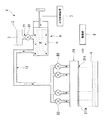
図1は、本発明の親水化処理装置の概略構成を示す図である。
親水化処理装置1は、図1に示されるように流路壁面に親水性を付与する親水性液状材
料2を収容したタンク3と、流路の上流側から供給される親水性液状材料を加圧するとと
もに流路の内部に充填する加圧機構4と、流路内に充填した親水性液状材料を排出した後
、インクジェット記録ヘッド24(以下、記録ヘッド24と称す)に乾燥処理を施すとと
もに、前記親水性液状材料の排出後、記録ヘッド24の乾燥処理に先立ち、ノズル形成面
の洗浄を行う管理部(乾燥機構、洗浄機構)8とを備えている。
FIG. 1 is a diagram showing a schematic configuration of a hydrophilic treatment apparatus of the present invention.
As shown in FIG. 1, the hydrophilization treatment apparatus 1 adds a
加圧機構4は加圧ポンプ6と加圧制御装置(加圧制御部)7とを備えている。加圧制御
装置7は例えばコンピュータ等によって構成されており、加圧ポンプ6を制御可能とする
ものである。加圧ポンプ6の一端にはチューブT1を介してタンク3が接続されており、
チューブT1にはタンク3から加圧ポンプ6内へのインク流量を調節するバルブB1が設
けられており、バルブB1は不図示のバルブ制御装置によって開閉度が調整される。
The pressurizing mechanism 4 includes a pressurizing pump 6 and a pressurizing control device (pressurizing control unit) 7. The pressurization control device 7 is configured by a computer or the like, for example, and can control the pressurization pump 6. A
The tube T1 is provided with a valve B1 for adjusting the ink flow rate from the
また、上記管理部8は、親水性液状材料が付着した流路壁面を良好に乾燥させる、例え
ばヒータ等の乾燥機構を含んでいる。さらに、管理部8は、ノズル形成面211Aに親水
性液状材料を洗浄可能とする洗浄液(例えば、純水)を供給する洗浄液供給部(不図示)
と、ノズル形成面211Aに供給した洗浄液を掻き取るヘラ等の洗浄液掻取部とを備える
洗浄機構を含んでいる。
In addition, the
And a cleaning liquid scraping part such as a spatula for scraping the cleaning liquid supplied to the
また、加圧ポンプ6の他端にはチューブT2を介してインクジェット記録ヘッド24が
接続される。チューブT2のヘッド側は4つに分岐されており、それぞれが同色のインク
を供給するインク導入口に接続されている。これにより、同色のインクが流れる流路に対
して親水性液状材料を個別に通液させることが可能となっている。また、チューブT2の
分岐部分にはインクジェット記録ヘッド24へのインク流量調整及びノズル処理列の選択
を行うためのバルブB2がそれぞれ設けられている。
The other end of the pressurizing pump 6 is connected to the ink
本実施形態では親水性液状材料として、ポリマー等の親水性樹脂、具体的に本実施形態
ではポリビニルアルコール(PVA)を用いた。なお、親水性液状材料としては、これに
限定されることはなく、例えば親水性エマルジョン等を用いてもよい。
In this embodiment, a hydrophilic resin such as a polymer, specifically, polyvinyl alcohol (PVA) is used in this embodiment as the hydrophilic liquid material. In addition, as a hydrophilic liquid material, it is not limited to this, For example, you may use a hydrophilic emulsion etc.
ここで、親水化処理装置1を用いた親水化処理方法についての説明に先んじて、本発明
の親水化処理装置1によって親液化処理が施されたインクジェット記録ヘッド24、及び
該インクジェット記録ヘッド24を備えるインクジェットプリンタ(流体噴射装置)の構
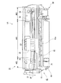
成について図面を参照して説明する。図2は本発明の一実施形態に係るインクジェットプ
リンタIJ1の内部構造の概略を示す斜視図であり、図3は同正面図であり、図4は同側
断面図である。
Here, prior to the description of the hydrophilic treatment method using the hydrophilic treatment apparatus 1, the
図2から図4に示されるようにインクジェットプリンタIJ1は、印刷用紙Pを給送す
る給紙ユニット10、インクジェット記録ヘッド24及びキャリッジ22を備えるキャリ
ッジユニット20、印刷用紙Pを搬送する搬送ユニット60、インクジェット記録ヘッド
24のメンテナンスを行うインクシステムユニット50を備えている。
そして、搬送ユニット60の上側にキャリッジユニット20が、側方にインクシステム
ユニット50がそれぞれ連結し、キャリッジユニット20の背面側に給紙ユニット10が
連結し、4つのユニットが合体するように構成されている。
As shown in FIGS. 2 to 4, the ink jet printer IJ1 includes a
The
給紙ユニット10は、給紙ユニットフレーム12、給紙ローラ13、可動ガイド14,
固定ガイド15及びホッパ16等を備える。そして、給紙ユニットフレーム12に対して
、給紙ローラ13の回動軸13a、ホッパ16等が取り付けられる。
The
A fixed
キャリッジユニット20は、キャリッジガイド軸25、キャリッジモータ27、従動プ
ーリ29及び用紙検出器36等を備える。また、キャリッジユニット20には、排紙フレ
ーム30が取り付けられる。
キャリッジモータ27には、駆動プーリ28が取り付けられ、駆動プーリ28と従動プ
ーリ29との間にキャリッジベルト26が掛架される。そして、キャリッジベルト26に
はキャリッジ22が固定され、当該キャリッジ22は、キャリッジモータ27の回動によ
って、キャリッジガイド軸25に沿って主走査方向に往復動するようになっている。
The
A driving
搬送ユニット60は、搬送ユニットフレーム61、搬送駆動ローラ62、搬送従動ロー
ラ63、搬送従動ローラホルダ64、排紙駆動ローラ軸65a及び紙案内67等を備える
。そして、搬送ユニットフレーム61に対して、搬送駆動ローラ62、搬送従動ローラホ
ルダ64、排紙駆動ローラ軸65a及び紙案内67等が取り付けられる。また、搬送ユニ
ットフレーム61には、プラテン66が形成される。
The
また、搬送ユニット60は、駆動モータ69を備え、この駆動モータ69により、給紙
ローラ13、搬送駆動ローラ62、排紙駆動ローラ65及びインクシステムユニット50
が駆動されるようになっている。
Further, the
Is to be driven.
インクシステムユニット50は、インク受部材及びブレードユニット(いずれも不図示
)を備えており、搬送ユニットフレーム61の側方に連結される。
インク受部材は、インクの乾燥防止のために行われるフラッシング処理の際に、インク
ジェット記録ヘッド24から連続的に吐出されるインクを受け取るものである。そして、
インク受部材は、排出チューブを介して廃インクタンクに接続されており、インク受部材
に溜まったインクが廃インクタンクに送られるようになっている。
ブレードユニットは、キャリッジ22の往復動領域を横切る位置と往復動領域から退避
する位置とを移動可能に構成され、例えば、キャリッジ22が印字領域からホームポジシ
ョンに移動する際に、インクジェット記録ヘッド24のノズル面を払拭することでクリー
ニングを行う。
The
The ink receiving member receives ink that is continuously ejected from the
The ink receiving member is connected to a waste ink tank via a discharge tube, and the ink accumulated in the ink receiving member is sent to the waste ink tank.
The blade unit is configured to be movable between a position crossing the reciprocation area of the
インクジェットプリンタIJ1の上流側(インクジェットプリンタIJ1の後方側)に
配置されるホッパ16上には、例えばA4サイズ等の印刷用紙Pが傾斜姿勢で堆積・収納
される。ホッパ16は、上部に位置する回動支点(不図示)を中心に回動可能に構成され
ており、回動することによりその下部が給紙ローラ13に対して圧接したり、離間したり
する様になっている。また、ホッパ16上の印刷用紙Pは、ホッパ16の幅方向にスライ
ド可能な可動ガイド14と固定ガイド15により、その側端がガイドされる。そして、印
刷用紙Pのうちの最上位のものは、ホッパ16が給紙ローラ13に対して圧接した際に、
給紙ローラ13の回動動作に伴って、下流側(インクジェットプリンタIJ1の前方側)
に繰り出されるようになっている。
On the
As the
It comes to be drawn out.
給紙ローラ13は、側面視略D形の形状を有しており、回動軸13aが回動駆動される
ことによって回動する。そして、この給紙ローラ13は、印刷動作時にはその平坦部が印
刷用紙Pに対向する状態に制御され、これによって印刷用紙Pの搬送負荷の発生を防止す
るようになっている。
The
紙案内67は、給紙ローラ13よりも下流側下方に、略水平に配置されており、給紙ロ
ーラ13によって繰り出された印刷用紙Pの先端が紙案内67に斜めに当接し、滑らかに
下流側に案内されるようになっている。更に下流側には、回動駆動する搬送駆動ローラ6
2と、この搬送駆動ローラ62に圧接する搬送従動ローラ63とが設けられており、印刷
用紙Pが搬送駆動ローラ62と搬送従動ローラ63とにニップされて、一定ピッチで下流
側に搬送される。
なお、搬送従動ローラ63は、搬送従動ローラホルダ(不図示)によって、常に搬送駆
動ローラ62に対して圧接するように付勢される。
The
2 and a transport driven
The transport driven
搬送駆動ローラ62の下流には、プラテン66及びインクジェット記録ヘッド24が上
下方向に対向して配設されており、印刷用紙Pが搬送駆動ローラ62の回動によってイン
クジェット記録ヘッド24の下へ搬送され、更にプラテン66によって下から支持される
ようになっている。
A
インクジェット記録ヘッド24は、インクカートリッジ23を搭載するキャリッジ22
の底部に設けられている。そして、キャリッジ22が主走査方向に延びるキャリッジガイ
ド軸25にガイドされながら主走査方向に往復動する際に、インクジェット記録ヘッド2
4は、印刷用紙Pに向けてブラック、イエロー、シアン、マゼンダ等のインクを吐出する
。
なお、インクカートリッジ23は、例えば、4つのカートリッジ(すなわち、4色のイ
ンク(ブラック、イエロー、シアン、マゼンダ)がそれぞれ別個独立に充填された容器)
からなり、それぞれが別個独立に交換可能となっている。
The ink
At the bottom. When the
4 ejects black, yellow, cyan, magenta and the like toward the printing paper P.
The
Each can be exchanged independently.
インクジェット記録ヘッド24よりも下流には、排紙駆動ローラ65と、排紙従動ロー
ラ31と、排紙補助ローラ32とが配設される。排紙駆動ローラ65は、主走査方向に延
びる排紙駆動ローラ軸65aに対して複数個取り付けられる。排紙従動ローラ31は、排
紙駆動ローラ65に軽く圧接することによって従動回動するように設けられている。した
がって、インクジェット記録ヘッド24によって印刷処理された印刷用紙Pは、排紙駆動
ローラ65と排紙従動ローラ31とによってニップされた状態で排紙駆動ローラ65が回
動することにより、下流側に排出される。
排紙補助ローラ32は、排紙従動ローラ31のやや上流側に設けられ、印刷用紙Pをや
や下方に押しつけて、印刷用紙Pのプラテン66からの浮き上がりを防止する。これによ
り、印刷用紙Pとインクジェット記録ヘッド24との距離を規制している。
A paper
The paper discharge
図5は、記録ヘッド24の断面構成の概略を示す図である。記録ヘッド24は、インク
を液滴状にしてノズル開口から吐出するものである。図5に示されるように記録ヘッド2
4は、インクが吐出されるノズル(ノズル開口)211に連通する圧力発生室221を構
成する流路形成基板220と、前記圧力発生室221の上面に配置され圧力発生室221
に圧力変化を生じさせる圧電素子300と、圧電素子300を覆う筐体310とを備えて
いる。
FIG. 5 is a diagram showing an outline of a cross-sectional configuration of the
4 is a flow
Are provided with a
流路形成基板220は基板本体410と該基板本体410上に貼り合わされた振動板4
00とから構成されている。また、基板本体410はプラスチック樹脂からなる板状部材
をポリプロピレンやPET等の接着剤250によって貼り合わせることで構成される。そ
して、流路形成基板220の下面側(圧電素子300とは反対側)には、複数のノズル2
11が形成されたノズル形成面211Aを有するノズル基板210が接着剤250を介し
て貼り合わされている。
The flow
00. The
A
ノズル基板210には、流路形成基板220と貼り合わせられたときに各圧力発生室2
21に対応する位置にノズル211が形成されている。また、各圧力発生室221間は不
図示の側壁で分離されており、供給口224を介して共通の流路であるリザーバ223に
繋がっている。また、筐体310には、リザーバ223にインクを供給するためのインク
導入口225が形成されており、流路形成基板220にはインク導入口225とリザーバ
223とを連通する導入路226が設けられている。インク導入口225は少なくともイ
ンクカートリッジ23から供給されるインク数(本実施形態では4つ)だけ設けられてい
る。
Each pressure generating chamber 2 is attached to the
このように記録ヘッド24における流路Rの壁面は、接着剤250による貼り合わせ構
造から構成されているため接着部で接着剤250のヒケが生じることで流路壁面に凹部が
形成されてしまう。ここで、流路Rとはインク導入口225を介して記録ヘッド24内に
導入したインクがノズル211に到達するまでに流れる領域に対応するものである。
As described above, since the wall surface of the flow path R in the
ところで、図6に示されるように親水化処理装置1による親水化処理を行っていない従
来の記録ヘッドは、流路壁面に形成される凹凸部(図中円で囲まれる領域)でインクの流
れによどみが生じ、発生した気泡Pが吸着されてしまう問題が生じる。
Incidentally, as shown in FIG. 6, the conventional recording head that has not been subjected to the hydrophilization treatment by the hydrophilization treatment apparatus 1 causes the ink flow at the uneven portions (area surrounded by a circle in the figure) formed on the flow path wall surface. A problem arises in which stagnation occurs and the generated bubbles P are adsorbed.
一方、図5に示されるような本実施形態に係る記録ヘッド24では、上述の親水化処理
装置1によって流路Rの内壁面に親水性膜Mが形成されている。この親水性膜Mは流路R
の内壁面における凹部を覆った状態となっている。このように流路Rの内壁面が親水性膜
Mで覆われるため、流路R内でスムーズな流れを得ることができる。
On the other hand, in the
It is in the state which covered the recessed part in the inner wall surface. Since the inner wall surface of the flow path R is thus covered with the hydrophilic film M, a smooth flow can be obtained in the flow path R.
(親水化処理方法)
続いて、親水化処理装置1の動作方法を述べることで、本発明の親水化処理方法の一実
施形態について説明する。
はじめに、図1に示したようにチューブT2を記録ヘッド24に接続する。具体的には
、記録ヘッド24のインク導入口225にチューブT2を接続する。そして、記録ヘッド
24のノズル形成面211Aに対向する位置に流路R内から排出させた親水性液状材料を
回収するための容器9を配置する。
(Hydrophilic treatment method)
Subsequently, an embodiment of the hydrophilic treatment method of the present invention will be described by describing the operation method of the hydrophilic treatment apparatus 1.
First, the tube T2 is connected to the
続いて、親水化処理装置1はバルブ制御装置によってバルブB1を開き、チューブT1
を介してタンク3内に貯留されている親液性液状材料を加圧ポンプ6内に流入させる。具
体的に本実施形態では、タンク3内にポリビニルアルコール(PVA)を希釈することな
く原液状態で貯留している。ポリビルアルコールの原液は高濃度であるため、非常に高い
親水性を有するものの、その粘性も高くなる。本実施形態に係る親水化処理装置1は、加
圧制御装置7が加圧ポンプ6内を駆動することで親液性液状材料を加圧しつつ、親液性液
状材料をチューブT2内に送り込む。このときチューブT2に設けられたバルブB2を開
くことでインク導入口225から記録ヘッド24(流路R)内に親液性液状材料を送り込
むことができる。
Subsequently, the hydrophilization treatment device 1 opens the valve B1 by the valve control device, and the tube T1.
The lyophilic liquid material stored in the
本実施形態では、加圧制御装置7が圧力に緩急をつけることで親液性液状材料の充填処
理を行う。このように加圧時の圧力に緩急をつけることで、粘性の高い親液性液状材料(
本実施形態では、ポリビニルアルコール(PVA))を流路R内に良好に充填することが
できる。
In the present embodiment, the pressurization control device 7 performs the filling process of the lyophilic liquid material by applying a gradual pressure. In this way, by adjusting the pressure at the time of pressurization, a highly viscous lyophilic liquid material (
In this embodiment, polyvinyl alcohol (PVA) can be satisfactorily filled in the flow path R.
ここで、加圧制御装置7による加圧ポンプ6の加圧方法のバリエーションについて説明
する。図7は加圧制御装置7から加圧ポンプ6に入力される信号を示すものであり、同図
中、横軸は時間を示し、縦軸は圧力の強さを示している。
図7(a)は所定間隔毎に正圧(圧縮)状態と圧力を印加しない状態とを繰り返すよう
な信号を加圧ポンプ6に送る場合を示している。すなわち、加圧ポンプ6はパルス的に親
液性液状材料に圧縮力を印加することとなる。ここで、所定間隔とは親液性液状材料を流
路R内に良好に流し込むことのできる流路Rの長さ、及び広さ等に応じて適宜設定される
。
また、図7(b)は正圧状態と負圧(吸引)状態とが交互に繰り返すような信号を加圧
ポンプ6に送る場合を示している。
また、図7(c)は図7(b)に示した正圧状態と負圧状態とを交互に繰り返すととも
に、印加する圧力の大きさを変化させるような信号を加圧ポンプ6に送る場合を示してい
る。
図7(a)〜(c)に示したように圧力に緩急をつけて加圧ポンプ6を駆動させること
で流路R内(リザーバ223、圧力発生室221等)に親水性液状材料(ポリビニルアル
コール)を良好に通液させて記録ヘッド24内の隅々まで良好に充填できる。
Here, the variation of the pressurization method of the pressurization pump 6 by the pressurization control apparatus 7 is demonstrated. FIG. 7 shows a signal input from the pressurization control device 7 to the pressurization pump 6. In the figure, the horizontal axis indicates time, and the vertical axis indicates pressure intensity.
FIG. 7A shows a case where a signal that repeats a positive pressure (compression) state and a state where no pressure is applied is sent to the pressurizing pump 6 at predetermined intervals. That is, the pressurizing pump 6 applies a compressive force to the lyophilic liquid material in a pulse manner. Here, the predetermined interval is appropriately set according to the length, width, and the like of the flow path R through which the lyophilic liquid material can be satisfactorily poured into the flow path R.
FIG. 7B shows a case in which a signal is sent to the pressurizing pump 6 so that a positive pressure state and a negative pressure (suction) state are alternately repeated.
FIG. 7C shows a case where the positive pressure state and the negative pressure state shown in FIG. 7B are alternately repeated and a signal for changing the magnitude of the applied pressure is sent to the pressurizing pump 6. Is shown.
As shown in FIGS. 7A to 7C, a hydrophilic liquid material (polyvinyl chloride) is formed in the flow path R (
本実施形態に係る記録ヘッド24は、流路Rを構成する流路形成基板220が接着剤2
50を介して複数の部材を貼り合わせて構成されるため、流路壁面は微小な凹凸部を有し
ている。上述したように加圧しながら流路Rの全域に充填された親水性液状材料(ポリビ
ニルアルコール)は凹凸部に付着し、上記凹凸部をコーティングしている。
In the
Since a plurality of members are bonded to each other via 50, the flow path wall surface has minute uneven portions. As described above, the hydrophilic liquid material (polyvinyl alcohol) filled in the entire region of the flow path R while being pressurized adheres to the uneven portions and coats the uneven portions.
親水性液状材料(ポリビニルアルコール)を記録ヘッド24内に充填した後、所定の時
間放置する。これにより流路Rの壁面に親水性処理材料を付着させることができる。その
後、流路Rの上流側から加圧することで親水性液状材料の排出処理を行う。具体的には、
加圧ポンプを動作させることで流路R内に空気圧を送り込むことでノズル211から親水
性液状材料を排出させる。
A hydrophilic liquid material (polyvinyl alcohol) is filled in the
The hydrophilic liquid material is discharged from the
ところで、流路Rの下流側であるノズル形成面211A側から吸引して親水性液状材料
を排出する場合、ノズル形成面211Aに親水性液状材料が多数付着してしまう。
一方、本実施形態では流路Rの上流側から加圧することで各ノズル211から親水性液
状材料を排出させているので、ノズル形成面211Aに付着する親水性液状材料の量を低
減できる。よって、後述するノズル形成面211Aの洗浄処理を簡略化できる。
By the way, when the hydrophilic liquid material is discharged by sucking from the
On the other hand, in this embodiment, since the hydrophilic liquid material is discharged from each
親液性液状材料の排出後、管理部8によって流路R内を乾燥させる。これにより、親液
性液状材料は乾燥定着し、流路壁面にポリビニルアルコールから構成される親水性膜Mを
形成する。この親水性膜Mは流路R内に形成された凹凸部をコーティングする膜であり、
図5に示したように接合部における接着剤250のヒケに起因する凹部を埋め込んだ状態
に形成される。よって、流路内壁面の凹凸部は親水性膜Mにより平滑化される。
After discharging the lyophilic liquid material, the inside of the flow path R is dried by the
As shown in FIG. 5, it forms in the state which the recessed part resulting from the sink of the
以上述べたように、本実施形態によれば、加圧することで高い親水性が得られるポリビ
ニルアルコールの原液を親水性液状材料として流路R内に通液させることで、流路R内に
接着剤250による貼り合わせ構造に起因する凹凸部を親水性膜Mによってコーティング
できる。よって、流路R内においてスムーズな流れを得ることができ、凹凸部での気泡滞
留を低減することで気泡排出を容易に行うことができる。よって、インク流れがよどむこ
とに起因する気泡滞留を低減できる。
As described above, according to the present embodiment, a polyvinyl alcohol stock solution that is highly hydrophilic by pressurization is allowed to pass through the flow path R as a hydrophilic liquid material, thereby adhering in the flow path R. The uneven part resulting from the bonding structure by the
(実験結果)
ここで、実施形態に係る方法により形成された親水性膜Mの効果を示す実験結果につい
て説明する。
図8は上述した本発明に係る親水化処理を施した流路R内における、気泡吸着の有無、
及び流路R内に入り込んだ気泡の排出能力を示す表であり、図8(a)は流路R内に純水
を流した場合を示し、図8(b)は流路R内にインクを流した場合を示している。なお、
同図中において静的接触角とは流路壁面における純水に対するものを意味している。また
、同表中、ポリプロピレンとは流路Rの接合部に用いられる接着剤250である。
(Experimental result)
Here, experimental results showing the effect of the hydrophilic film M formed by the method according to the embodiment will be described.
FIG. 8 shows the presence or absence of bubble adsorption in the flow path R subjected to the hydrophilic treatment according to the present invention described above.
FIG. 8A shows a case where pure water is allowed to flow in the flow path R, and FIG. 8B shows ink in the flow path R. FIG. It shows the case of flowing. In addition,
In the figure, the static contact angle means a value relative to pure water on the channel wall surface. Further, in the table, polypropylene is an adhesive 250 used for the joint portion of the flow path R.
図8(a)に示されるように処理面がポリプロピレンの場合(すなわち親水処理を行っ
ていない場合)、静的接触角が95〜100°と大きくなる。このように流路R内におけ
る親水性が低いと流路R内の接合部(接着剤250に起因する凹凸部)にて気泡吸着が発
生してしまう。すると、気泡排出処理としてチョーククリーニングのような強い吸引処理
を行ったとしても気泡を完全に除去することができなかった。
したがって、流路R内における気泡吸着を防止する、或いは気泡を排出するためには流
路R内の親水性を向上させるのが重要であることが確認できる。
As shown in FIG. 8A, when the treated surface is polypropylene (that is, when the hydrophilic treatment is not performed), the static contact angle is increased to 95 to 100 °. Thus, if the hydrophilicity in the flow path R is low, bubble adsorption will occur at the joint in the flow path R (uneven portions due to the adhesive 250). Then, even if a strong suction process such as chalk cleaning was performed as the bubble discharge process, the bubbles could not be completely removed.
Therefore, it can be confirmed that it is important to improve the hydrophilicity in the flow path R in order to prevent bubble adsorption in the flow path R or to discharge the bubbles.
また、流路R内でのポリビニルアルコールの流動性を高めるべく100倍に希釈して粘
度を5cp程度に設定した。なお、5cpとは流路R内を流れる一般的なインクの粘度と
同等の値である。
この場合、充分な親水性が得られないため(静的接触角60°)、依然として流路R内
にて気泡吸着が発生することが確認できた。また、気泡を排出するためにはチョーククリ
ーニングのような強力な吸引動作が必要となる。
Moreover, in order to improve the fluidity | liquidity of the polyvinyl alcohol in the flow path R, it diluted 100 times and set the viscosity to about 5 cp. Note that 5 cp is a value equivalent to the viscosity of general ink flowing in the flow path R.
In this case, since sufficient hydrophilicity was not obtained (
一方、本発明では、30cpといった高粘度のポリビニルアルコール原液であっても流
路R内に良好に通液させることで流路R内を親水性膜Mでコーティングしている。親水性
膜Mが形成された処理面は、静的接触角が45〜50°と小さくなり、高い親水性が付与
される。よって、流路R内にて気泡の吸着が発生することがないので、気泡排出処理とし
て低速クリーニング等の弱い吸引動作を行うことで気泡を流路R外に確実に排出できるこ
とが確認できた。
On the other hand, in the present invention, the inside of the flow path R is coated with the hydrophilic film M by allowing the polyvinyl alcohol stock solution having a high viscosity of 30 cp to flow through the flow path R satisfactorily. The treated surface on which the hydrophilic film M is formed has a static contact angle as small as 45 to 50 ° and is imparted with high hydrophilicity. Therefore, bubbles are not adsorbed in the flow path R, and it was confirmed that the bubbles can be reliably discharged out of the flow path R by performing a weak suction operation such as low-speed cleaning as the bubble discharge processing.
また、図8(b)に示される流路R内にインクを流す場合においても純水の場合と同様
、親水処理を行わない(本発明を適応しない場合)と流路R内に気泡吸着が発生してしま
い、チョーククリーニングを行った場合でも完全に気泡を除去することができない。
In addition, when ink is allowed to flow in the flow path R shown in FIG. 8B, as in the case of pure water, if the hydrophilic treatment is not performed (when the present invention is not applied), bubbles are adsorbed in the flow path R. Even when chalk cleaning is performed, bubbles cannot be completely removed.
一方、本発明を採用すれば、ポリビニルアルコールの原液から構成される親水性膜Mに
よって流路R内面がコーティングされ、高い親水性が付与される。
したがって、流路R内に純水を流す場合でも、流路R内にて気泡の吸着が発生すること
がなく気泡排出処理として低速クリーニング等の弱い吸引動作を行うことで気泡を流路R
外に確実に排出できることが確認できた。
On the other hand, if the present invention is adopted, the inner surface of the flow path R is coated with a hydrophilic film M composed of a polyvinyl alcohol stock solution, and high hydrophilicity is imparted.
Therefore, even when pure water is flowed into the flow path R, bubbles are not adsorbed in the flow path R, and bubbles are removed from the flow path R by performing a weak suction operation such as low-speed cleaning as a bubble discharge process.
It was confirmed that it can be reliably discharged outside.
本発明は上述した実施形態に限定されることはなく、発明の趣旨を逸脱しない範囲内に
おいて適宜変更可能である。
例えば、上記実施形態では、インク流路R内に同一の親水性液状材料を流入させ、同一
の親水性膜Mを形成しているが、例えば流路R毎に該流路R内を流れるインクに対して良
好な親水性を付与する親液性液状材料をそれぞれ流入させ、流路R毎にそれぞれ異なる親
水性膜を形成するようにしてもよい。
The present invention is not limited to the above-described embodiment, and can be changed as appropriate without departing from the spirit of the invention.
For example, in the above embodiment, the same hydrophilic liquid material is allowed to flow into the ink flow path R to form the same hydrophilic film M. For example, the ink flowing in the flow path R for each flow path R Alternatively, a lyophilic liquid material that imparts good hydrophilicity may be introduced to form a different hydrophilic film for each flow path R.
1…親水化処理装置、2…親水性液状材料、3…タンク、4…加圧機構、6…加圧ポンプ
、7…加圧制御装置(加圧制御部)、8…管理機構(乾燥機構、洗浄機構)、24…記録
ヘッド(噴射ヘッド)、211…ノズル(ノズル開口)、211A…ノズル形成面、M…
親水性膜、R…流路
DESCRIPTION OF SYMBOLS 1 ... Hydrophilization processing apparatus, 2 ... Hydrophilic liquid material, 3 ... Tank, 4 ... Pressure mechanism, 6 ... Pressure pump, 7 ... Pressure control apparatus (pressure control part), 8 ... Management mechanism (drying mechanism) , Cleaning mechanism), 24... Recording head (jetting head), 211... Nozzle (nozzle opening), 211 A.
Hydrophilic membrane, R ... channel
Claims (14)
る噴射ヘッドにおける前記流体の流路内に親水処理を施す親水化処理方法であって、
前記流路の上流側から加圧しつつ前記流路内に親水性液状材料を充填する工程と、
前記流路内から前記親水性液状材料を排出する工程と、
前記親水性液状材料の排出後、前記流路に乾燥処理を行う工程と、を備えることを特徴
とする親水化処理方法。 A hydrophilization method comprising a nozzle forming surface in which a plurality of nozzle openings are formed, and performing a hydrophilic treatment in the fluid flow path in an ejection head that ejects fluid from the nozzle openings,
Filling the flow path with a hydrophilic liquid material while applying pressure from the upstream side of the flow path;
Discharging the hydrophilic liquid material from the flow path;
And a step of performing a drying process on the flow channel after discharging the hydrophilic liquid material.
る請求項1に記載の親水化処理方法。 The hydrophilic treatment method according to claim 1, wherein the hydrophilic liquid material is discharged while being pressurized from the upstream side of the flow path.
うことを特徴とする請求項1又は2に記載の親水化処理方法。 The hydrophilic treatment method according to claim 1 or 2, wherein, in the step of filling the hydrophilic liquid material into the flow path, pressurization is performed while applying a gradual pressure.
力を加えることを特徴とする請求項3記載の親水化処理方法。 The hydrophilic treatment method according to claim 3, wherein pressure is applied from the upstream side of the flow path so as to alternately repeat a positive pressure state and a negative pressure state during the pressurization.
求項4に記載の親水化処理方法。 The hydrophilic treatment method according to claim 4, wherein the magnitude of pressure applied in the positive pressure state and the negative pressure state is changed.
を加えることを特徴とする請求項3に記載の親水化処理方法。 The hydrophilization method according to claim 3, wherein pressure is applied so as to repeat a positive pressure state and a state in which no pressure is applied at predetermined intervals during the pressurization.
する工程を備えることを特徴とする請求項1〜6のいずれか一項に記載の親水化処理方法
。 The hydrophilization treatment according to any one of claims 1 to 6, further comprising a step of cleaning the nozzle forming surface after discharging the hydrophilic liquid material and before the drying treatment of the flow path. Method.
る噴射ヘッドにおける前記流体の流路内に親水処理を施す親水化処理装置であって、
親水性液状材料を収容したタンクと、
前記流路の上流側から加圧するとともに前記流路内に前記親水性液状材料を充填する加
圧機構と、
前記親水性液状材料の排出後、前記流路内に乾燥処理を施す乾燥機構と、を備えること
を特徴とする親水化処理装置。 A hydrophilization treatment apparatus comprising a nozzle forming surface in which a plurality of nozzle openings are formed, and performing a hydrophilic treatment in the fluid flow path in an ejection head that ejects fluid from the nozzle openings,
A tank containing a hydrophilic liquid material;
A pressurizing mechanism for pressurizing from the upstream side of the flow path and filling the hydrophilic liquid material in the flow path;
And a drying mechanism that performs a drying process in the flow channel after discharging the hydrophilic liquid material.
該加圧制御部は圧力に緩急をつけて前記親液性液状材料の充填処理を行うことを特徴と
する請求項8に記載の親水化処理装置。 The pressurization mechanism has a pressurization control unit that controls the pressurization state,
9. The hydrophilization apparatus according to claim 8, wherein the pressurizing control unit performs the filling process of the lyophilic liquid material by applying a gradual pressure.
することを特徴とする請求項9に記載の親水化処理装置。 The hydrophilic treatment apparatus according to claim 9, wherein the pressurization control unit controls the pressurization mechanism to alternately repeat a positive pressure state and a negative pressure state.
とを特徴とする請求項10に記載の親水化処理装置。 The hydrophilization processing apparatus according to claim 10, wherein the pressurization control unit can adjust the magnitude of the pressure applied during the positive pressure and the negative pressure.
前記加圧機構を制御することを特徴とする請求項9に記載の親水化処理装置。 The hydrophilic treatment apparatus according to claim 9, wherein the pressurization control unit controls the pressurization mechanism to repeat a positive pressure state and a state where no pressure is applied at predetermined intervals.
を洗浄する洗浄機構を備えることを特徴とする請求項7〜12のいずれか一項に記載の親
水化処理装置。 The hydrophilization treatment according to claim 7, further comprising a cleaning mechanism for cleaning the nozzle formation surface after the discharge of the hydrophilic liquid material and prior to the drying processing of the ejection head. apparatus.
体噴射装置であって、
前記噴射ヘッドにおける前記流体の流路内面に親水性膜が形成されており、該親水性膜
は前記内壁面の凹凸部を覆うことを特徴とする流体噴射装置。 A fluid ejecting apparatus including an ejecting head that ejects fluid from a plurality of nozzle openings formed on a nozzle forming surface,
A fluid ejecting apparatus, wherein a hydrophilic film is formed on an inner surface of the fluid flow path in the ejecting head, and the hydrophilic film covers an uneven portion of the inner wall surface.
Priority Applications (1)
| Application Number | Priority Date | Filing Date | Title |
|---|---|---|---|
| JP2007227382A JP2009056752A (en) | 2007-09-03 | 2007-09-03 | Hydrophilizing treatment method, hydrophilizing treatment device, and fluid jetting device |
Applications Claiming Priority (1)
| Application Number | Priority Date | Filing Date | Title |
|---|---|---|---|
| JP2007227382A JP2009056752A (en) | 2007-09-03 | 2007-09-03 | Hydrophilizing treatment method, hydrophilizing treatment device, and fluid jetting device |
Publications (2)
| Publication Number | Publication Date |
|---|---|
| JP2009056752A true JP2009056752A (en) | 2009-03-19 |
| JP2009056752A5 JP2009056752A5 (en) | 2010-08-19 |
Family
ID=40552929
Family Applications (1)
| Application Number | Title | Priority Date | Filing Date |
|---|---|---|---|
| JP2007227382A Withdrawn JP2009056752A (en) | 2007-09-03 | 2007-09-03 | Hydrophilizing treatment method, hydrophilizing treatment device, and fluid jetting device |
Country Status (1)
| Country | Link |
|---|---|
| JP (1) | JP2009056752A (en) |
Cited By (2)
| Publication number | Priority date | Publication date | Assignee | Title |
|---|---|---|---|---|
| JP2012030492A (en) * | 2010-07-30 | 2012-02-16 | Brother Industries Ltd | Liquid ejection apparatus |
| JP2020040345A (en) * | 2018-09-12 | 2020-03-19 | ブラザー工業株式会社 | head |
Citations (1)
| Publication number | Priority date | Publication date | Assignee | Title |
|---|---|---|---|---|
| JP2004017415A (en) * | 2002-06-14 | 2004-01-22 | Hitachi Printing Solutions Ltd | Process for manufacturing inkjet head and inkjet printer |
-
2007
- 2007-09-03 JP JP2007227382A patent/JP2009056752A/en not_active Withdrawn
Patent Citations (1)
| Publication number | Priority date | Publication date | Assignee | Title |
|---|---|---|---|---|
| JP2004017415A (en) * | 2002-06-14 | 2004-01-22 | Hitachi Printing Solutions Ltd | Process for manufacturing inkjet head and inkjet printer |
Cited By (4)
| Publication number | Priority date | Publication date | Assignee | Title |
|---|---|---|---|---|
| JP2012030492A (en) * | 2010-07-30 | 2012-02-16 | Brother Industries Ltd | Liquid ejection apparatus |
| JP2020040345A (en) * | 2018-09-12 | 2020-03-19 | ブラザー工業株式会社 | head |
| JP7135627B2 (en) | 2018-09-12 | 2022-09-13 | ブラザー工業株式会社 | head |
| US11440320B2 (en) | 2018-09-12 | 2022-09-13 | Brother Kogyo Kabushiki Kaisha | Liquid discharge head |
Similar Documents
| Publication | Publication Date | Title |
|---|---|---|
| JP6477829B2 (en) | Cleaning method for fluid ejection device | |
| JP5620726B2 (en) | Liquid discharge head and ink jet recording apparatus | |
| JP6256692B2 (en) | Liquid ejecting apparatus and control method thereof | |
| JP2007331116A (en) | Inkjet recorder | |
| JP2011161714A (en) | Liquid ejecting apparatus, and nozzle recovery method in liquid ejecting apparatus | |
| JP5720319B2 (en) | Liquid ejection head, liquid ejection apparatus, and image forming apparatus | |
| JP4986546B2 (en) | LIQUID DISCHARGE HEAD, LIQUID DISCHARGE DEVICE, IMAGE FORMING APPARATUS, AND LIQUID DISCHARGE HEAD MANUFACTURING METHOD | |
| JP2007229959A (en) | Liquid discharge method/device and imaging device | |
| JP6069994B2 (en) | Cap member, liquid ejection device, and image forming apparatus | |
| JP7150048B2 (en) | PRINTING HEAD CLEANING DEVICE, PRINTING HEAD CLEANING METHOD, AND PRINTING APPARATUS | |
| JP6683946B2 (en) | Liquid ejection head and liquid ejection device | |
| JP2018094868A (en) | Inkjet printer and method for cleaning ink head in inkjet printer | |
| JP2009056752A (en) | Hydrophilizing treatment method, hydrophilizing treatment device, and fluid jetting device | |
| US10259225B2 (en) | Recording head and ink-jet recording apparatus provided with the same | |
| JP2005125653A (en) | Inkjet head, inkjet recorder, and device and method of cleaning inkjet head | |
| US20050068373A1 (en) | Liquid filling method, droplet discharging apparatus, and inkjet recording apparatus | |
| JP2005131791A (en) | Ink jet head and ink jet recorder | |
| JP6274275B2 (en) | Liquid ejection head, liquid ejection apparatus, and image forming apparatus | |
| JP2009012370A (en) | Fluid jet apparatus and maintenance method of fluid jet apparatus | |
| JP4841386B2 (en) | Liquid ejection device and method for cleaning liquid ejection device | |
| JP6041010B2 (en) | Liquid ejection head, liquid ejection apparatus, and image forming apparatus | |
| JP2012139991A (en) | Inkjet head, and inkjet recording apparatus | |
| JP2014046643A (en) | Suction cap for head and image formation device | |
| JP2016199032A (en) | Liquid discharge head, liquid discharge unit and device for discharging liquid | |
| JP2022113527A (en) | Nozzle surface cleaning device and liquid discharge device |
Legal Events
| Date | Code | Title | Description |
|---|---|---|---|
| A521 | Written amendment |
Free format text: JAPANESE INTERMEDIATE CODE: A523 Effective date: 20100707 |
|
| A621 | Written request for application examination |
Free format text: JAPANESE INTERMEDIATE CODE: A621 Effective date: 20100707 |
|
| A977 | Report on retrieval |
Free format text: JAPANESE INTERMEDIATE CODE: A971007 Effective date: 20120209 |
|
| A131 | Notification of reasons for refusal |
Effective date: 20120214 Free format text: JAPANESE INTERMEDIATE CODE: A131 |
|
| A761 | Written withdrawal of application |
Effective date: 20120411 Free format text: JAPANESE INTERMEDIATE CODE: A761 |