JP2009041941A - Gas concentration measuring device and method - Google Patents
Gas concentration measuring device and method Download PDFInfo
- Publication number
- JP2009041941A JP2009041941A JP2007204369A JP2007204369A JP2009041941A JP 2009041941 A JP2009041941 A JP 2009041941A JP 2007204369 A JP2007204369 A JP 2007204369A JP 2007204369 A JP2007204369 A JP 2007204369A JP 2009041941 A JP2009041941 A JP 2009041941A
- Authority
- JP
- Japan
- Prior art keywords
- measurement target
- wavelength
- light
- target gas
- laser
- Prior art date
- Legal status (The legal status is an assumption and is not a legal conclusion. Google has not performed a legal analysis and makes no representation as to the accuracy of the status listed.)
- Pending
Links
Images


Landscapes
- Investigating Or Analysing Materials By Optical Means (AREA)
Abstract
Description
本発明はガス濃度測定装置およびガス濃度測定方法に関し、特に、周波数変調されたレーザ光を用いてガスの濃度を測定する方法に適用して好適なものである。 The present invention relates to a gas concentration measuring apparatus and a gas concentration measuring method, and is particularly suitable for application to a method of measuring a gas concentration using a frequency-modulated laser beam.
気体状のガス分子にはそれぞれ固有の光吸収スペクトルが有ることが知られており、ガス分子の吸収線の中心周波数における減衰量はガスの濃度に比例する。このため、ガス分子の吸収線の中心周波数に一致した発振周波数をもつ半導体レーザ光をガスに照射し、その時のレーザ光の減衰量を測定することで、ガスの濃度を推定することができる(特許文献1)。 It is known that each gaseous gas molecule has its own light absorption spectrum, and the attenuation at the center frequency of the absorption line of the gas molecule is proportional to the gas concentration. For this reason, the gas concentration can be estimated by irradiating the gas with semiconductor laser light having an oscillation frequency that matches the center frequency of the absorption line of gas molecules, and measuring the attenuation of the laser light at that time ( Patent Document 1).
この原理を発展させたものとして2波長差分方式及び周波数変調方式があり、2波長差分方式では、半導体レーザの発振周波数はTHzオーダの信号であることから、複雑な信号処理を行うことができないのに対して、周波数変調方式では、数kHzのベースバンド領域で信号処理を行うことができるという利点がある。
ここで、周波数変調方式では、ガスの吸収線幅よりもレーザ光の線幅の方が小さいことから、ガスの吸収波長と半導体レーザの発光波長とを合わせる必要がある。この方法として、予め測定したいガスと同じ成分を封入した参照ガスセルを用いる方法がある(特許文献2)。
The two-wavelength difference method and the frequency modulation method are developed from this principle. In the two-wavelength difference method, since the oscillation frequency of the semiconductor laser is a signal on the order of THz, complicated signal processing cannot be performed. On the other hand, the frequency modulation method has an advantage that signal processing can be performed in a baseband region of several kHz.
Here, in the frequency modulation method, since the line width of the laser beam is smaller than the absorption line width of the gas, it is necessary to match the absorption wavelength of the gas with the emission wavelength of the semiconductor laser. As this method, there is a method using a reference gas cell in which the same component as the gas to be measured is enclosed (Patent Document 2).
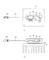
図12(a)は、従来の周波数変調方式におけるガス濃度測定装置の概略構成を示す平面図、図12(b)は、従来の周波数変調方式におけるガス濃度測定装置の概略構成を示す側面図である。
図12において、光源ユニットには、半導体レーザモジュール121、参照ガスセル122およびフォト検出器123が収容され、光源ユニットのケース本体126の底面には、冷却用フィン127が取り付けられたペルチェ素子128が配設されている。ここで、半導体レーザモジュール121には、周波数変調されたレーザ光を両面から出射する半導体レーザが配設されるとともに、コネクタ125aを備えた光ケーブル125が延出され、半導体レーザから出射される一方の光が光ケーブル125を介して測定対象ガスの雰囲気に出射される。
FIG. 12A is a plan view showing a schematic configuration of a gas concentration measuring device in a conventional frequency modulation method, and FIG. 12B is a side view showing a schematic configuration of the gas concentration measuring device in a conventional frequency modulation method. is there.
In FIG. 12, the light source unit contains a
また、参照ガスセル122は、半導体レーザの後ろ側の光路上に配設され、参照ガスセル122を通過したレーザ光は、参照ガスセル122の後ろ側に配設されたフォト検出器123によって受光検出される。
そして、参照ガスセル122を通過したレーザ光を参照しながらペルチェ素子128にて半導体レーザの温度制御を行い、2倍波と基本波との比が最大となるように半導体レーザの発光波長を制御することにより、ガスの吸収波長と半導体レーザの発光波長とを合わせることができる。
Then, the temperature of the semiconductor laser is controlled by the Peltier
しかしながら、従来の周波数変調方式におけるガス濃度の測定方法では、煙道などから排出される複数種類のガスの濃度を同時に計測する場合、1つの半導体レーザで可変できる波長の範囲が狭く、1台の成分計では1成分または特定の2成分しか計測できないため、単成分計を複数台設置する必要がある。このため、設置面積、設置工事費および光軸調整費などが設置台数に比例して増大し、計測システムの大型化や高価格化を招くという問題があった。
そこで、本発明の目的は、発光素子の波長可変範囲を超える吸収特性を持つ複数種類のガスの濃度を単成分計にて計測することが可能なガス濃度測定装置およびガス濃度測定方法を提供することである。
However, in the conventional gas concentration measurement method in the frequency modulation method, when simultaneously measuring the concentrations of a plurality of types of gases discharged from a flue or the like, the wavelength range that can be varied by one semiconductor laser is narrow, and one unit Since the component meter can measure only one component or two specific components, it is necessary to install a plurality of single component meters. For this reason, the installation area, the installation work cost, the optical axis adjustment cost, etc. increase in proportion to the number of installations, and there is a problem that the measurement system is increased in size and price.
Accordingly, an object of the present invention is to provide a gas concentration measuring apparatus and a gas concentration measuring method capable of measuring concentrations of a plurality of types of gases having absorption characteristics exceeding the wavelength variable range of the light emitting element with a single component meter. That is.
上述した課題を解決するために、請求項1記載のガス濃度測定装置によれば、2成分以上の測定対象ガスの吸収波長にそれぞれ対応した波長を有するレーザ光を出射する複数の発光素子と、前記発光素子からそれぞれ出射されたレーザ光を共通の変調周波数で周波数変調させる高周波変調信号を発生する高周波変調信号発生部と、前記周波数変調されたレーザ光の発光波長にて測定対象ガスの特定の成分の吸収波長帯をそれぞれスキャンさせる波長走査駆動信号を発生する波長走査駆動信号発生器と、前記高周波変調信号および前記波長走査駆動信号に基づいて前記発光素子をそれぞれ駆動することにより、前記発光素子の発光波長を変調させるレーザ駆動信号発生部と、前記レーザ駆動信号発生部にて駆動される発光素子を時系列的に切り替える切り替え制御手段と、前記レーザ駆動信号発生部にて駆動されるレーザ光の発光波長が前記測定対象ガスの特定の成分の吸収波長帯にそれぞれかかるように前記発光素子の温度を設定する温度設定部と、前記レーザ駆動信号発生部にてそれぞれ周波数変調された複数のレーザ光を共通に検出する光検出部と、前記複数の発光素子から出射されたレーザ光を前記光検出部に導く光反射手段と、前記光検出部にて検出されたレーザ光から基本波成分を検出する基本波成分検出部と、前記光検出部にて検出されたレーザ光から2倍波成分を検出する2倍波成分検出部と、前記基本波成分と2倍波成分との振幅比に基づいて、前記レーザ光が透過した測定対象ガスの特定の成分の濃度をそれぞれ算出するガス濃度算出部とを備えることを特徴とする。 In order to solve the above-described problem, according to the gas concentration measuring device of claim 1, a plurality of light emitting elements that emit laser beams having wavelengths respectively corresponding to absorption wavelengths of two or more components of the measurement target gas; A high-frequency modulation signal generating unit that generates a high-frequency modulation signal for frequency-modulating the laser light emitted from each of the light-emitting elements with a common modulation frequency; and a specific gas to be measured at an emission wavelength of the frequency-modulated laser light A wavelength scanning drive signal generator for generating a wavelength scanning driving signal for scanning each absorption wavelength band of the component; and driving the light emitting element based on the high frequency modulation signal and the wavelength scanning driving signal, respectively, The laser drive signal generator for modulating the emission wavelength of the light source and the light emitting elements driven by the laser drive signal generator are switched in time series. And a temperature setting for setting the temperature of the light emitting element so that the emission wavelength of the laser light driven by the laser drive signal generator is in the absorption wavelength band of the specific component of the measurement target gas. , A light detection unit for commonly detecting a plurality of laser beams frequency-modulated by the laser drive signal generation unit, and a light reflection for guiding the laser beams emitted from the plurality of light emitting elements to the light detection unit Means, a fundamental wave component detector for detecting a fundamental wave component from the laser light detected by the light detector, and a second harmonic for detecting a second harmonic component from the laser light detected by the light detector. A component detection unit, and a gas concentration calculation unit that calculates a concentration of a specific component of the measurement target gas transmitted by the laser beam based on an amplitude ratio between the fundamental wave component and the second harmonic component. Features and That.
また、請求項2記載のガス濃度測定装置によれば、前記複数の発光素子の一部は、レーザ光の発光波長が前記測定対象ガスの吸収波長帯にかからないように選択されることを特徴とする。
また、請求項3記載のガス濃度測定方法によれば、2成分以上の測定対象ガスの吸収波長にそれぞれ対応した波長を有するレーザ光を共通の変調周波数で周波数変調させるステップと、前記周波数変調されたレーザ光の発光波長が測定対象ガスの特定の成分の吸収波長帯にそれぞれかかるように、前記レーザ光をそれぞれ出射する発光素子の温度を設定するステップと、前記周波数変調されたレーザ光の発光波長を測定対象ガスの特定の成分の吸収波長帯がスキャンされるようにそれぞれ変化させながら、前記測定対象ガスに前記レーザ光を順次入射させるステップと、前記測定対象ガスを順次透過したレーザ光を共通の検出器にて検出するステップと、前記検出器にて順次検出されたレーザ光から基本波成分および2倍波成分を抽出するステップと、前記抽出された基本波成分および2倍波成分に基づいて、前記レーザ光が透過した測定対象ガスの特定の成分の濃度をそれぞれ算出するステップとを備えることを特徴とする。
According to the gas concentration measuring apparatus of
According to the gas concentration measurement method of claim 3, the step of frequency-modulating laser light having wavelengths respectively corresponding to the absorption wavelengths of the gas to be measured having two or more components at a common modulation frequency, and the frequency modulation Setting the temperature of each light emitting element that emits the laser light so that the emission wavelength of the laser light is applied to the absorption wavelength band of the specific component of the measurement target gas, and the emission of the frequency-modulated laser light Sequentially changing the wavelength so that the absorption wavelength band of a specific component of the measurement target gas is scanned, and sequentially entering the laser light into the measurement target gas; and laser light sequentially passing through the measurement target gas A step of detecting by a common detector, and a step of extracting a fundamental wave component and a second harmonic component from the laser light sequentially detected by the detector. And-up, on the basis of the extracted fundamental frequency component and second harmonic component, characterized in that it comprises a step of calculating the concentration of a particular component of the measurement object gas to the laser light is transmitted, respectively.
また、請求項4記載のガス濃度測定方法によれば、2成分以上の測定対象ガスの吸収波長にそれぞれ対応した波長を有するレーザ光を共通の変調周波数で周波数変調させるステップと、前記周波数変調されたレーザ光の発光波長が測定対象ガスの特定の成分の吸収波長帯にそれぞれかかるように、前記レーザ光をそれぞれ出射する発光素子の温度を設定するステップと、前記周波数変調されたレーザ光の発光波長を測定対象ガスの特定の成分の吸収波長帯がスキャンされるようにそれぞれ変化させながら、前記測定対象ガスに前記レーザ光を順次入射させるステップと、前記測定対象ガスを順次透過したレーザ光を共通の検出器にて検出するステップと、前記検出器にて順次検出されたレーザ光から基本波成分および2倍波成分を抽出するステップと、前記抽出された基本波成分および2倍波成分に基づいて、前記レーザ光が透過した測定対象ガスの特定の成分の濃度をそれぞれ算出するステップと、前記測定対象ガスの吸収波長にかからない波長を有するレーザ光を前記変調周波数で周波数変調させるステップと、前記測定対象ガスの吸収波長にかからない波長を有するレーザ光を前記測定対象ガスに入射させるステップと、前記測定対象ガスの吸収波長にかからない波長を有するレーザ光を前記検出器にて検出するステップと、前記検出器にて検出された前記測定対象ガスの吸収波長にかからない波長を有するレーザ光から基本波成分および2倍波成分を抽出するステップと、前記測定対象ガスの吸収波長にかからない波長を有するレーザ光から抽出された基本波成分および2倍波成分に基づいて、前記レーザ光が透過した測定対象ガスの濃度を補正するステップとを備えることを特徴とする。 According to the gas concentration measuring method of claim 4, the step of frequency-modulating laser light having wavelengths respectively corresponding to the absorption wavelengths of the gas to be measured having two or more components at a common modulation frequency, and the frequency modulation Setting the temperature of each light emitting element that emits the laser light so that the emission wavelength of the laser light is applied to the absorption wavelength band of the specific component of the measurement target gas, and the emission of the frequency-modulated laser light Sequentially changing the wavelength so that the absorption wavelength band of a specific component of the measurement target gas is scanned, and sequentially entering the laser light into the measurement target gas; and laser light sequentially passing through the measurement target gas A step of detecting by a common detector, and a step of extracting a fundamental wave component and a second harmonic component from the laser light sequentially detected by the detector. And calculating the concentration of the specific component of the measurement target gas transmitted by the laser beam based on the extracted fundamental wave component and the second harmonic component, and the absorption wavelength of the measurement target gas. A step of frequency-modulating a laser beam having a wavelength that is not affected by the modulation frequency, a step of causing a laser beam having a wavelength that does not depend on the absorption wavelength of the measurement target gas to be incident on the measurement target gas, and an absorption wavelength of the measurement target gas A step of detecting a laser beam having a wavelength that is not affected by the detector, and extracting a fundamental wave component and a second harmonic component from the laser beam having a wavelength that is not affected by the absorption wavelength of the measurement target gas detected by the detector; A fundamental wave component extracted from a laser beam having a wavelength that does not depend on the absorption wavelength of the measurement target gas, and 2 Based on the wave component, characterized in that it comprises a step of correcting the concentration of the measurement target gas in which the laser light is transmitted.
以上説明したように、本発明によれば、発光波長が互いに異なる複数の発光素子からレーザ光を時系列的に出射させ、吸収波長が互いに異なる2成分以上の測定対象ガスを透過させてから、単一の光検出部にて検出することにより、単一の発光素子の波長可変範囲を超える吸収特性を持つ複数種類のガスの濃度を単成分計にて計測することが可能となり、計測システムの大型化や高価格化を抑制しつつ、煙道などから排出される複数種類のガスの濃度を計測することができる。 As described above, according to the present invention, laser light is emitted from a plurality of light emitting elements having different emission wavelengths from each other in time series, and two or more measurement target gases having different absorption wavelengths are allowed to pass through. By detecting with a single light detector, it is possible to measure the concentration of multiple types of gases with absorption characteristics exceeding the wavelength variable range of a single light emitting element with a single component meter. It is possible to measure the concentration of multiple types of gas discharged from a flue while suppressing the increase in size and price.
以下、本発明の実施形態に係るガス濃度測定装置について図面を参照しながら説明する。
図1は、本発明の一実施形態に係るガス濃度測定装置における光学系の概略構成を示す断面図である。
図1において、ガス濃度測定装置の送信側の光学系には、2成分以上の測定対象ガスの吸収波長にそれぞれ対応した波長を有するレーザ光を出射する複数の発光素子5a〜5d、発光素子5a〜5dからそれぞれ出射されたレーザ光の光軸を同一方向に一致させるプリズム型ミラー6が設けられている。なお、プリズム型ミラー6には、反射面を4面設けることができ、発光素子5a〜5dからそれぞれ出射されたレーザ光をプリズム型ミラー6の各面で反射させることにより、発光素子5a〜5dからそれぞれ出射されたレーザ光の光軸を同一方向に一致させることができる。なお、発光素子5a〜5dとしては、DFBレーザ(Distributed Feedback Laser)やVCSEL(Vertical Cavity Surface Emitting Laser)などの半導体レーザを用いることができる。
Hereinafter, a gas concentration measuring apparatus according to an embodiment of the present invention will be described with reference to the drawings.
FIG. 1 is a cross-sectional view showing a schematic configuration of an optical system in a gas concentration measuring apparatus according to an embodiment of the present invention.
In FIG. 1, the optical system on the transmission side of the gas concentration measuring device includes a plurality of
また、ガス濃度測定装置の受信側の光学系には、測定対象ガスを透過したレーザ光を集光する集光レンズ9、測定対象ガスを透過したレーザ光を検出する受光素子10が設けられている。なお、受光素子10としては、例えば、フォトダイオードを用いることができる。そして、受光素子10は、測定対象ガスを透過したレーザ光の基本波成分と2倍波成分との振幅比を算出する信号処理装置11に接続されている。
The optical system on the receiving side of the gas concentration measuring device is provided with a
ここで、発光素子5a〜5dおよびプリズム型ミラー6はハウジング4に収容されるとともに、集光レンズ9、受光素子10、および信号処理装置11はハウジング8に収容されている。そして、煙道などの測定対象ガスが流れる配管などの隔壁1a、1bには、固定フランジ2a、2bが溶接などの方法にて取り付けられる。そして、発光素子5a〜5dおよびプリズム型ミラー6が収容されたハウジング4は、光軸調整用の調整フランジ3aを介してフランジ2aに取り付けられるとともに、ウェッジ窓7aにて配管内と仕切られている。また、集光レンズ9、受光素子10、および信号処理装置11が収容されたハウジング8は、光軸調整用の調整フランジ3bを介してフランジ2bに取り付けられるとともに、ウェッジ窓7bにて配管内と仕切られている。なお、ウェッジ窓7a、7bとしては、溶融石英などを材料として構成することができる。
Here, the
そして、中心周波数fc、変調周波数fmで発光素子5a〜5dの出力が周波数変調されるとともに、測定対象ガスの特定の成分の吸収波長帯がそれぞれスキャンされるようにレーザ光の発光波長が変化されながら、発光素子5a〜5dからレーザ光が順次出射される。そして、発光素子5a〜5dから出射されたレーザ光は、プリズム型ミラー6にて受光素子10の方向に反射された後、ウェッジ窓7aを介して隔壁1a、1b間の測定対象ガスを透過する。そして、測定対象ガスを透過したレーザ光は、測定対象ガスのガス分子の吸収線に対応した波長の吸収を受けた後、ウェッジ窓1bを介して集光レンズ9に入射し、集光レンズ9にて受光素子10の受光面上に集光される。そして、受光素子10にレーザ光が入射すると、受光素子10にて電気信号に変換され、その電気信号が信号処理装置11に送られる。そして、受光素子10にて変換された電気信号が信号処理装置11に送られると、測定対象ガスの特定の成分の吸収波長帯にかかる部分についての基本波成分と2倍波成分との振幅比が信号処理装置11にて順次算出され、測定対象ガスの特定の成分の濃度を順次算出することができる。
The output of the
これにより、発光波長が互いに異なる複数の発光素子5a〜5dからレーザ光を時系列的に出射させ、吸収波長が互いに異なる2成分以上の測定対象ガスを透過させてから、単一の受光素子10にて検出することができる。このため、単一の発光素子5a〜5dの波長可変範囲を超える吸収特性を持つ複数種類のガスの濃度を単成分計にて計測することが可能となり、計測システムの大型化や高価格化を抑制しつつ、煙道などから排出される複数種類のガスの濃度を計測することができる。
Thereby, laser light is emitted from a plurality of
図2は、図1のガス濃度測定装置における送信側の信号処理部の概略構成を示すブロック図である。
図2において、ガス濃度測定装置の送信側には、複数の発光素子5a〜5dが設けられ、発光素子5a〜5dには、発光素子5a〜5dの温度をそれぞれ検出する温度検出素子16a〜16dおよび発光素子5a〜5dの温度をそれぞれ調整する温度調整素子17a〜17dが搭載されている。なお、温度検出素子16a〜16dとしては、例えば、サーミスタ、温度調整素子17a〜17dとしては、例えば、ペルチェ素子を用いることができる。また、温度検出素子16a〜16dは、発光素子5a〜5dに直接接触させることなく、アルミニウムなどの熱伝導性のよい材料に穴を空け、熱伝導性のよいシリコーンなどの樹脂を用いることで、サーミスタなどの温度検出素子16a〜16dをその穴に埋め込むようにしてもよい。
FIG. 2 is a block diagram showing a schematic configuration of a signal processing unit on the transmission side in the gas concentration measuring apparatus of FIG.
In FIG. 2, a plurality of
そして、ペルチェ素子などの温度調整素子17a〜17dは、温度検出素子16a〜16dが埋め込まれたアルミブロックを介して発光素子5a〜5dに装着することができる。
なお、発光素子5a〜5dの温度を制御する温度制御素子としては、例えば、マキシム社製MAX1978やリニアテクノロジ社製LTC1923などを用いることができる。
The
As the temperature control element for controlling the temperature of the
また、発光素子5a〜5dからそれぞれ出射されたレーザ光を共通の変調周波数で周波数変調させる高周波変調信号を発生する高周波変調信号発生部13a〜13d、周波数変調されたレーザ光の発光波長にて測定対象ガスの特定の成分の吸収波長帯をそれぞれスキャンさせる波長走査駆動信号を発生する波長走査駆動信号発生器12、高周波変調信号発生部13a〜13dにてそれぞれ発生された高周波変調信号および波長走査駆動信号発生器12にてそれぞれ発生された波長走査駆動信号に基づいて発光素子5a〜5dをそれぞれ駆動することにより、発光素子5a〜5dの発光波長を変調させるレーザ駆動信号発生部14a〜14d、レーザ駆動信号発生部14a〜14dにてそれぞれ駆動される発光素子5a〜5dを時系列的に切り替える切り替え制御部19、温度検出素子16a〜16dにて検出された温度に基づいて温度調整素子17a〜17dを駆動する温度制御回路18a〜18dが設けられている。
Further, high frequency
そして、温度検出素子16a〜16dにて検出された温度は温度制御回路18a〜18dに入力され、温度制御回路18a〜18dは、温度検出素子16a〜16dにて検出された温度に基づいて温度調整素子17a〜17dを駆動することにより、発光素子5a〜5dから出射されるレーザ光の発光波長が測定対象ガスの特定の成分の吸収波長帯にそれぞれかかるように発光素子5a〜5dの温度をそれぞれ制御する。例えば、温度制御回路18a〜18dは、温度検出素子16a〜16dとして用いられるサーミスタの抵抗値が一定になるように、温度調整素子17a〜17dとして用いられるペルチェ素子のPID制御などを行うことにより、発光素子5a〜5dの温度を調整し、発光素子5a〜5dから出射されるレーザ光の発光波長を一定に保つことができる。
The temperatures detected by the
そして、レーザ駆動信号発生部14a〜14dは切り替え制御部19にて時系列的に選択されながら、波長走査駆動信号発生器12にて発生された波長走査駆動信号および高周波変調信号発生部13a〜13dにてそれぞれ発生された高周波変調信号がレーザ駆動信号発生部14a〜14dに順次入力される。
そして、レーザ駆動信号発生部14a〜14dに順次入力された波長走査駆動信号および高周波変調信号は、レーザ駆動信号発生部14a〜14dにてそれぞれ合成され、電圧−電流変換処理が行われた後、発光素子5a〜5dに順次注入される。そして、発光素子5a〜5dに電流が順次注入されると、測定対象ガスの特定の成分の吸収波長帯をそれぞれスキャンする波長帯で発光素子5a〜5dが順次発光し、図1のプリズム型ミラー6を介して測定対象ガスに入射した後、受光素子10にて検出される。
The laser
Then, the wavelength scanning drive signal and the high frequency modulation signal sequentially input to the laser
なお、図2の実施形態では、発光素子5a〜5dに対して波長走査駆動信号発生器12を共通に設けるとともに、高周波変調信号発生部13a〜13dを個別に設ける方法について説明したが、高周波変調信号発生部13a〜13dは発光素子5a〜5dに対して共通に設けるようにしてもよい。ただし、受光素子10にて検出された信号の信号処理を同一の回路で行えるようにするために、高周波変調信号の周波数は同一に設定するのが好ましい。なお、高周波変調信号の周波数は同一に設定した場合、波長スキャン幅や波長変調幅は互いに異なっていてもよい。
In the embodiment of FIG. 2, the wavelength scanning
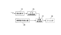
図3は、図1のガス濃度測定装置における受信側の信号処理部の概略構成を示すブロック図である。
図3において、ガス濃度測定装置の受信側には、発光素子5a〜5dからそれぞれ出射されたレーザ光を共通に検出する受光素子10、受光素子10から出力される電流を電圧に変換するI−V変換回路25、高周波変調信号の2倍の周波数の信号を発生させる参照信号発生器26、I−V変換回路25の出力から高周波変調信号の2倍の周波数成分を抽出する同期検波器27、同期検波器27の出力から不要な帯域成分を除去するフィルタ28が設けられている。
FIG. 3 is a block diagram showing a schematic configuration of a signal processing unit on the receiving side in the gas concentration measuring apparatus of FIG.
In FIG. 3, on the receiving side of the gas concentration measuring apparatus, a
そして、発光素子5a〜5からそれぞれ出射されたレーザ光は測定対象ガスを通過すると、測定対象ガスの特定の成分による吸収量に対応した減衰を受けた後、受光素子10に入射し、受光素子10にてレーザ光が検出される。そして、受光素子10にて検出された電流はI−V変換回路25にて電圧に変換され、参照信号発生器26にて発生された2倍周波数信号とI−V変換回路25からの出力が同期検波器27にて合成されることにより、I−V変換回路25の出力から高周波変調信号の2倍の周波数成分が抽出され、フィルタ28にてノイズが除去される。
Then, when the laser light emitted from each of the
図4は、本発明の一実施形態に係る周波数変調方式によるガス濃度の測定原理を説明する図である。
図4において、中心周波数fc、変調周波数fmで発光素子5a〜5dの出力をそれぞれ周波数変調し、測定対象ガスに照射されたものとする。ここで、測定対象ガスの吸収線は変調周波数に対してほぼ2次関数となっているので、この吸収線が弁別器の役割を果たし、受光素子10では変調周波数fmの2倍の周波数の成分(2倍波成分)が得られる。ここで、変調周波数fmは任意の周波数でよいので、例えば、変調周波数fmを数kHz程度に選ぶと、ディジタル信号処理装置(DSP)または汎用のプロセッサを用い高度な信号処理を施すことが可能となる。
FIG. 4 is a view for explaining the principle of measuring the gas concentration by the frequency modulation method according to one embodiment of the present invention.
In FIG. 4, it is assumed that the outputs of the
そして、発光素子5a〜5dと受光素子10との距離に起因するレーザ光の減衰量の影響を周波数変調方式にてキャンセルするためには、発光素子5a〜5dの出力に周波数変調を行うと同時に変調周波数fmで振幅変調を行えばよく、発光素子5a〜5dの出力に周波数変調をかけることで振幅変調もかけることができる。そして、光検出側でエンベロープ検波をそれぞれ行うことで振幅変調による基本波成分を推定することができ、この基本波成分の振幅と2倍波成分の振幅の比を位相同期させて取ることで、発光素子5a〜5dと受光素子10との距離に依存することなく、測定対象ガスの濃度に比例した値をそれぞれ得ることができる。
In order to cancel the influence of the attenuation amount of the laser light caused by the distance between the
図5は、本発明の一実施形態に係る駆動電流と半導体レーザの発光波長との関係を示す図である。
図5において、発光素子5a〜5dからそれぞれ出射されるレーザ光の発光波長は駆動電流が増加するに従って長くなる。このため、発光素子5a〜5dの駆動電流を制御することにより、発光素子5a〜5dからそれぞれ出射されるレーザ光の発光波長を調整することができる。
図6は、本発明の一実施形態に係る温度と半導体レーザの発光波長との関係を示す図である。
図6において、発光素子5a〜5dからそれぞれ出射されるレーザ光の発光波長は温度が増加するに従って長くなる。このため、発光素子5a〜5dの温度を制御することにより、発光素子5a〜5dからそれぞれ出射されるレーザ光の発光波長を調整することができる。
FIG. 5 is a diagram showing the relationship between the drive current and the emission wavelength of the semiconductor laser according to one embodiment of the present invention.
In FIG. 5, the emission wavelength of the laser light emitted from each of the
FIG. 6 is a diagram showing the relationship between the temperature and the emission wavelength of the semiconductor laser according to one embodiment of the present invention.
In FIG. 6, the emission wavelength of the laser light emitted from each of the
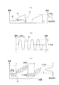
図7(a)は、図2の波長走査駆動信号発生器12にて生成される電流波形を示す図、図7(b)は、図2の高周波変調信号発生部13a〜13dにて生成される電流波形を示す図、図7(c)は、図7(a)の電流波形と図7(b)の電流波形とが合成された信号を印加した時に発光素子5a〜5dから出射される光の波長の変化を示す図である。
図7において、図2の波長走査駆動信号発生器12にて発生される波長走査信号は、強度が一定に保たれた部分20と、強度が台形状に直線的に増加する部分19と、強度が0である部分21とから構成することができる。ここで、強度が台形状に直線的に増加する部分19は、測定対象ガスの特定の成分の吸収波長帯が走査されるように、発光素子5a〜5dからそれぞれ出射されるレーザ光の波長を徐々に変化させることができる。
7A is a diagram showing a current waveform generated by the wavelength scanning
7, the wavelength scanning signal generated by the wavelength scanning
そして、測定対象ガスの濃度を測定する場合、図2の温度制御回路18a〜18dは、温度検出素子16a〜16dにて検出された温度を参照しながら温度調整素子17a〜17dを駆動することにより、波長走査信号の強度が直線的に増加する部分19の中心付近で測定対象ガスの特定の成分の濃度が検出されるように、発光素子5a〜5dの温度をそれぞれ事前に設定する。
And when measuring the density | concentration of measurement object gas, the
そして、図2の波長走査駆動信号発生器12は、発光素子5a〜5dの発光をそれぞれ安定化させるために、波長走査信号の強度が一定に保たれた部分20が発光素子5a〜5dのスレッショルドカレント以上になるようにして一定に保ちながら、波長走査信号の強度が一定に保たれた部分20をレーザ駆動信号発生部14a〜14dに出力するとともに、高周波変調信号発生部13a〜13dは周波数が10kHz、波長変調幅が0.02nmの正弦波からなる高周波変調信号22をレーザ駆動信号発生部14a〜14dにそれぞれ出力する。
The wavelength scanning
そして、波長走査信号の強度が一定に保たれた部分20と高周波変調信号22とはレーザ駆動信号発生部14a〜14dにてそれぞれ合成され、波長走査信号の強度が一定に保たれた部分20と高周波変調信号22が合成された信号に基づいて発光素子5a〜5dの電流がそれぞれ制御されることにより、測定対象ガスによる吸収を受けない波長を中心として10kHz程度の正弦波にてレーザ光が周波数変調される。
Then, the
そして、周波数変調されたレーザ光は測定対象ガスを通過すると、測定対象ガスによる吸収を受けることなく受光素子10に入射し、受光素子10にてレーザ光が検出される。そして、受光素子10にて検出された電流はI−V変換回路25にて電圧に変換され、参照信号発生器26にて発生された2倍周波数信号とI−V変換回路25からの出力が同期検波器27にて合成されることにより、I−V変換回路25の出力から高周波変調信号22の2倍の周波数成分が抽出される。ここで、測定対象ガスによる吸収を受けない波長を中心としてレーザ光が周波数変調されると、I−V変換回路25の出力から高周波変調信号22の2倍の周波数成分が抽出されることはなく、同期検波器27からの出力は一定となる。
When the frequency-modulated laser light passes through the measurement target gas, it enters the
次に、図2の波長走査駆動信号発生器12は、測定対象ガスの特定の成分の吸収波長帯をスキャンさせるために、波長走査信号の強度を台形状に直線的に増加させることで、波長走査信号の強度が台形状に直線的に増加する部分19をレーザ駆動信号発生部14a〜14dに出力するとともに、高周波変調信号発生部13a〜13dは周波数が10kHz、波長変調幅が0.02nmの正弦波からなる高周波変調信号22をレーザ駆動信号発生部14a〜14dにそれぞれ出力する。なお、波長走査駆動信号発生器12は、測定対象ガスの特定の成分の吸収波長帯が走査されるように波長走査信号の波長スキャン幅を発光素子5a〜5dごとに個別に設定することができ、例えば、発光素子5aから出射されたレーザ光にて、NH3ガスの濃度を測定する場合、波長走査駆動信号発生器12は、発光素子5aに対する波長スキャン幅を0.2nm程度に設定することができる。
Next, the wavelength scanning
そして、波長走査信号の強度が台形状に直線的に増加する部分19と高周波変調信号22とはレーザ駆動信号発生部14a〜14dにてそれぞれ合成され、波長走査信号の強度が台形状に直線的に増加する部分19と高周波変調信号22とが合成された信号に基づいて発光素子5a〜5dの電流がそれぞれ制御されることにより、測定対象ガスの特定の成分の吸収波長帯を含むように10kHz程度の正弦波にてレーザ光が周波数変調される。
Then, the
そして、周波数変調されたレーザ光は測定対象ガスを通過すると、測定対象ガスによる吸収量に対応した減衰を受けた後、受光素子10に入射し、受光素子10にてレーザ光が検出される。そして、受光素子10にて検出された電流はI−V変換回路25にて電圧に変換され、参照信号発生器26にて発生された2倍周波数信号とI−V変換回路25からの出力が同期検波器27にて合成されることにより、I−V変換回路25の出力から高周波変調信号22の2倍の周波数成分が抽出される。
ここで、測定対象ガスの特定の成分の吸収波長帯を含むように周波数変調されたレーザ光は測定対象ガスの特定の成分による吸収量に対応した減衰を受けるため、同期検波器27からの出力は測定対象ガスの特定の成分による吸収波形に対応した値となる。
When the frequency-modulated laser light passes through the measurement target gas, the laser light is attenuated corresponding to the amount of absorption by the measurement target gas, and then enters the
Here, since the laser light frequency-modulated to include the absorption wavelength band of the specific component of the measurement target gas is attenuated corresponding to the amount of absorption by the specific component of the measurement target gas, the output from the
図8は、図1のガス濃度測定装置における発光素子5a〜5dの駆動方法を示すタイミングチャートである。
図8において、測定対象ガスには吸収波長が互いに異なる4つの成分が含まれ、測定対象ガスの吸収波長帯は単一の発光素子5a〜5dの波長可変範囲を超えているものとする。
そして、発光素子5aは、その波長可変範囲が測定対象ガスの第1の成分の吸収波長帯に対応するように発光波長を選択し、発光素子5bは、その波長可変範囲が測定対象ガスの第2の成分の吸収波長帯に対応するように発光波長を選択し、発光素子5cは、その波長可変範囲が測定対象ガスの第3の成分の吸収波長帯に対応するように発光波長を選択し、発光素子5dは、その波長可変範囲が測定対象ガスの第4の成分の吸収波長帯に対応するように発光波長を選択することができる。
FIG. 8 is a timing chart showing a driving method of the
In FIG. 8, it is assumed that the gas to be measured includes four components having different absorption wavelengths, and the absorption wavelength band of the gas to be measured exceeds the wavelength variable range of the single
The
そして、図2の切り替え制御部19は、レーザ駆動信号発生部14a〜14dを時系列的に選択し、発光素子5a〜5dを規定の時間だけ順次オンさせることにより、発光素子5a〜5dからそれぞれ出射されたレーザ光を測定対象ガスに順次入射させることができる。そして、測定対象ガスを透過したレーザ光は共通の受光素子10にて順次検出され、測定対象ガスの4つの成分の濃度を順次算出することができる。
Then, the switching
図9(a)は、NH3ガスの吸収スペクトラムの一例を示す図、図9(b)は、HClガスの吸収スペクトラムの一例を示す図、図9(c)は、H2Sガスの吸収スペクトラムの一例を示す図、図9(d)は、CH4ガスの吸収スペクトラムの一例を示す図、図10は、図1のガス濃度測定装置における受光素子10の検出感度を波長に対して示す図である。
9A shows an example of an absorption spectrum of NH 3 gas, FIG. 9B shows an example of an absorption spectrum of HCl gas, and FIG. 9C shows the absorption of H 2 S gas. FIG. 9D is a diagram showing an example of a spectrum, FIG. 9D is a diagram showing an example of an absorption spectrum of CH 4 gas, and FIG. 10 shows the detection sensitivity of the
図9において、測定対象ガスには、NH3ガス、HClガス、H2Sガス、CH4ガスの4種類が含まれているとする。この場合、この測定対象ガスの吸収特性を有する波長帯は1600nm〜2000nmの範囲に及ぶため、単一の発光素子5a〜5dの波長可変範囲ではカバーすることができない。このため、発光素子5aは、その波長可変範囲がNH3ガスの吸収波長帯に対応するように発光波長を選択し、発光素子5bは、その波長可変範囲がHClガスの吸収波長帯に対応するように発光波長を選択し、発光素子5cは、その波長可変範囲がH2Sガスの吸収波長帯に対応するように発光波長を選択し、発光素子5dは、その波長可変範囲がCH4ガスの吸収波長帯に対応するように発光波長を選択することができる。
9, the measurement target gas, and NH 3 gas, HCl gas, H 2 S gas contains four CH 4 gas. In this case, since the wavelength band having the absorption characteristics of the measurement target gas extends in the range of 1600 nm to 2000 nm, it cannot be covered by the wavelength variable range of the single
一方、受光素子10としては、図10に示すように、1600nm〜2000nmの範囲に波長感度を持つフォトダイオードを選択することにより、NH3ガス、HClガス、H2Sガス、CH4ガスの吸収特性をカバーすることができ、単一の受光素子10を用いることで、NH3ガス、HClガス、H2Sガス、CH4ガスの濃度を計測することができる。
なお、1600nm〜2000nmの範囲に波長感度を持つフォトダイオードとしては、例えば、浜松フォトニクス製G8372−01を用いることができる。
On the other hand, as the
For example, G8372-01 manufactured by Hamamatsu Photonics can be used as the photodiode having wavelength sensitivity in the range of 1600 nm to 2000 nm.
図11は、図3の同期検波器の出力波形の一例を示す図である。
図11において、例えば、NH3ガスの吸光特性がある場合、図3の同期検波器27の出力波形には、ピークが発生する。そして、吸光特性はピーク値がそのままガス濃度を表すため、ピークの振幅を測定したり、出力波形の変化部分を積分したりすることで、NH3ガスの濃度を測定することができる。
なお、上述した実施形態では、波長可変範囲が測定対象ガスの特定の成分の吸収波長帯にそれぞれ対応するように発光素子5a〜5dの発光波長を選択する方法について説明したが、全ての発光素子5a〜5dの発光波長を測定対象ガスの特定の成分の吸収波長帯にそれぞれ対応させる必要はなく、受光素子10が感度を持つ範囲内において、複数の発光素子5a〜5dのうちの一部は、測定対象ガスによる吸収がない発光波長を選択するようにしてもよい。
FIG. 11 is a diagram illustrating an example of an output waveform of the synchronous detector of FIG.
In FIG. 11, for example, when there is an absorption characteristic of NH 3 gas, a peak occurs in the output waveform of the
In the above-described embodiment, the method of selecting the emission wavelengths of the
例えば、複数の発光素子5a〜5dのうちの発光素子5aについては、水分の吸収波長帯に対応するように発光波長を選択することができる。そして、発光素子5aから出射されたレーザ光を測定対象ガスに透過させ、そのレーザ光を受光素子10にて検出することにより、水分によるレーザ光の吸収量を測定することができる。そして、水分によるレーザ光の吸収量の測定結果に基づいて、発光素子5b〜5dを用いて測定された測定対象ガスの特定の成分の濃度を補正することで、ダストの影響を除去することができ、測定対象ガスの特定の成分の濃度の測定精度を向上させることができる。
For example, for the
1a、1b 隔壁
2a、2b 固定フランジ
3a、3b 調整フランジ
4、8 ハウジング
5a〜5d 発光素子
6 プリズム型ミラー
7a、7b 窓材
9 集光レンズ
10 受光素子
11 信号処理装置
12 波長走査駆動信号発生器
13a〜13d 高周波変調信号発生部
14a〜14d レーザ駆動信号発生部
16a〜16d 温度検出素子
17a〜17d 温度調整素子
18a〜18d 温度制御回路
19 切り替え制御部
25 IV変換回路
26 参照信号発生器
27 同期検波器
28 フィルタ
DESCRIPTION OF
Claims (4)
前記発光素子からそれぞれ出射されたレーザ光を共通の変調周波数で周波数変調させる高周波変調信号を発生する高周波変調信号発生部と、
前記周波数変調されたレーザ光の発光波長にて測定対象ガスの特定の成分の吸収波長帯をそれぞれスキャンさせる波長走査駆動信号を発生する波長走査駆動信号発生器と、
前記高周波変調信号および前記波長走査駆動信号に基づいて前記発光素子をそれぞれ駆動することにより、前記発光素子の発光波長を変調させるレーザ駆動信号発生部と、
前記レーザ駆動信号発生部にて駆動される発光素子を時系列的に切り替える切り替え制御手段と、
前記レーザ駆動信号発生部にて駆動されるレーザ光の発光波長が前記測定対象ガスの特定の成分の吸収波長帯にそれぞれかかるように前記発光素子の温度を設定する温度設定部と、
前記レーザ駆動信号発生部にてそれぞれ周波数変調された複数のレーザ光を共通に検出する光検出部と、
前記複数の発光素子から出射されたレーザ光を前記光検出部に導く光反射手段と、
前記光検出部にて検出されたレーザ光から基本波成分を検出する基本波成分検出部と、
前記光検出部にて検出されたレーザ光から2倍波成分を検出する2倍波成分検出部と、
前記基本波成分と2倍波成分との振幅比に基づいて、前記レーザ光が透過した測定対象ガスの特定の成分の濃度をそれぞれ算出するガス濃度算出部とを備えることを特徴とするガス濃度測定装置。 A plurality of light emitting elements that emit laser beams having wavelengths respectively corresponding to absorption wavelengths of two or more measurement target gases;
A high-frequency modulation signal generator for generating a high-frequency modulation signal for frequency-modulating the laser light emitted from each of the light emitting elements at a common modulation frequency;
A wavelength scanning drive signal generator for generating a wavelength scanning drive signal for scanning each absorption wavelength band of a specific component of the measurement target gas at the emission wavelength of the frequency-modulated laser light;
A laser drive signal generator for modulating the light emission wavelength of the light emitting element by driving the light emitting element based on the high frequency modulation signal and the wavelength scanning drive signal;
Switching control means for switching light emitting elements driven by the laser drive signal generation unit in time series;
A temperature setting unit for setting the temperature of the light emitting element so that the emission wavelength of the laser light driven by the laser drive signal generation unit is applied to the absorption wavelength band of the specific component of the measurement target gas;
A light detection unit for commonly detecting a plurality of laser beams, each of which is frequency-modulated by the laser drive signal generation unit;
A light reflecting means for guiding laser light emitted from the plurality of light emitting elements to the light detection unit;
A fundamental wave component detector that detects a fundamental wave component from the laser light detected by the light detector; and
A second harmonic component detection unit for detecting a second harmonic component from the laser light detected by the light detection unit;
A gas concentration comprising: a gas concentration calculation unit that calculates a concentration of a specific component of the measurement target gas transmitted by the laser beam based on an amplitude ratio between the fundamental wave component and the second harmonic wave component. measuring device.
前記周波数変調されたレーザ光の発光波長が測定対象ガスの特定の成分の吸収波長帯にそれぞれかかるように、前記レーザ光をそれぞれ出射する発光素子の温度を設定するステップと、
前記周波数変調されたレーザ光の発光波長を測定対象ガスの特定の成分の吸収波長帯がスキャンされるようにそれぞれ変化させながら、前記測定対象ガスに前記レーザ光を順次入射させるステップと、
前記測定対象ガスを順次透過したレーザ光を共通の検出器にて検出するステップと、
前記検出器にて順次検出されたレーザ光から基本波成分および2倍波成分を抽出するステップと、
前記抽出された基本波成分および2倍波成分に基づいて、前記レーザ光が透過した測定対象ガスの特定の成分の濃度をそれぞれ算出するステップとを備えることを特徴とするガス濃度測定方法。 Frequency-modulating laser beams having wavelengths respectively corresponding to absorption wavelengths of two or more components of the measurement target gas with a common modulation frequency;
Setting the temperature of each of the light emitting elements that emits the laser light such that the emission wavelength of the frequency-modulated laser light is applied to the absorption wavelength band of a specific component of the measurement target gas;
Sequentially changing the emission wavelength of the frequency-modulated laser light so that the absorption wavelength band of a specific component of the measurement target gas is scanned, and sequentially making the laser light incident on the measurement target gas;
Detecting a laser beam sequentially transmitted through the measurement target gas with a common detector;
Extracting a fundamental wave component and a second harmonic component from the laser light sequentially detected by the detector;
Calculating a concentration of a specific component of the measurement target gas transmitted by the laser beam based on the extracted fundamental wave component and second harmonic component, respectively.
前記周波数変調されたレーザ光の発光波長が測定対象ガスの特定の成分の吸収波長帯にそれぞれかかるように、前記レーザ光をそれぞれ出射する発光素子の温度を設定するステップと、
前記周波数変調されたレーザ光の発光波長を測定対象ガスの特定の成分の吸収波長帯がスキャンされるようにそれぞれ変化させながら、前記測定対象ガスに前記レーザ光を順次入射させるステップと、
前記測定対象ガスを順次透過したレーザ光を共通の検出器にて検出するステップと、
前記検出器にて順次検出されたレーザ光から基本波成分および2倍波成分を抽出するステップと、
前記抽出された基本波成分および2倍波成分に基づいて、前記レーザ光が透過した測定対象ガスの特定の成分の濃度をそれぞれ算出するステップと、
前記測定対象ガスの吸収波長にかからない波長を有するレーザ光を前記変調周波数で周波数変調させるステップと、
前記測定対象ガスの吸収波長にかからない波長を有するレーザ光を前記測定対象ガスに入射させるステップと、
前記測定対象ガスの吸収波長にかからない波長を有するレーザ光を前記検出器にて検出するステップと、
前記検出器にて検出された前記測定対象ガスの吸収波長にかからない波長を有するレーザ光から基本波成分および2倍波成分を抽出するステップと、
前記測定対象ガスの吸収波長にかからない波長を有するレーザ光から抽出された基本波成分および2倍波成分に基づいて、前記レーザ光が透過した測定対象ガスの濃度を補正するステップとを備えることを特徴とするガス濃度測定方法。 Frequency-modulating laser beams having wavelengths respectively corresponding to absorption wavelengths of two or more components of the measurement target gas with a common modulation frequency;
Setting the temperature of each of the light emitting elements that emits the laser light such that the emission wavelength of the frequency-modulated laser light is applied to the absorption wavelength band of a specific component of the measurement target gas;
Sequentially changing the emission wavelength of the frequency-modulated laser light so that the absorption wavelength band of a specific component of the measurement target gas is scanned, and sequentially making the laser light incident on the measurement target gas;
Detecting a laser beam sequentially transmitted through the measurement target gas with a common detector;
Extracting a fundamental wave component and a second harmonic component from the laser light sequentially detected by the detector;
Calculating a concentration of a specific component of the measurement target gas transmitted by the laser beam based on the extracted fundamental wave component and second harmonic wave component;
Frequency-modulating a laser beam having a wavelength that does not depend on the absorption wavelength of the measurement target gas with the modulation frequency;
Making the laser beam having a wavelength that does not depend on the absorption wavelength of the gas to be measured enter the gas to be measured;
Detecting a laser beam having a wavelength that does not depend on an absorption wavelength of the measurement target gas with the detector;
Extracting a fundamental wave component and a second harmonic component from a laser beam having a wavelength that does not depend on the absorption wavelength of the measurement target gas detected by the detector;
Correcting the concentration of the measurement target gas transmitted by the laser beam based on the fundamental wave component and the second harmonic component extracted from the laser beam having a wavelength that does not depend on the absorption wavelength of the measurement target gas. A characteristic gas concentration measurement method.
Priority Applications (1)
| Application Number | Priority Date | Filing Date | Title |
|---|---|---|---|
| JP2007204369A JP2009041941A (en) | 2007-08-06 | 2007-08-06 | Gas concentration measuring device and method |
Applications Claiming Priority (1)
| Application Number | Priority Date | Filing Date | Title |
|---|---|---|---|
| JP2007204369A JP2009041941A (en) | 2007-08-06 | 2007-08-06 | Gas concentration measuring device and method |
Publications (1)
| Publication Number | Publication Date |
|---|---|
| JP2009041941A true JP2009041941A (en) | 2009-02-26 |
Family
ID=40442848
Family Applications (1)
| Application Number | Title | Priority Date | Filing Date |
|---|---|---|---|
| JP2007204369A Pending JP2009041941A (en) | 2007-08-06 | 2007-08-06 | Gas concentration measuring device and method |
Country Status (1)
| Country | Link |
|---|---|
| JP (1) | JP2009041941A (en) |
Cited By (7)
| Publication number | Priority date | Publication date | Assignee | Title |
|---|---|---|---|---|
| JP2013113664A (en) * | 2011-11-28 | 2013-06-10 | Yokogawa Electric Corp | Laser gas analyzer |
| JP2013117517A (en) * | 2011-11-02 | 2013-06-13 | Fuji Electric Co Ltd | Laser type gas analyzer |
| JP2013127385A (en) * | 2011-12-19 | 2013-06-27 | Fuji Electric Co Ltd | Laser gas analyzer |
| CN103323423A (en) * | 2013-05-24 | 2013-09-25 | 深圳市赛宝伦计算机技术有限公司 | Anti-interference method and system for gas concentration analysis based on laser |
| WO2016111441A1 (en) * | 2015-01-08 | 2016-07-14 | 한국표준과학연구원 | Remote detection-use frequency and intensity modulated laser absorption spectroscopy device and method |
| WO2020157882A1 (en) * | 2019-01-31 | 2020-08-06 | 日本電気株式会社 | Receiver, system for early detection of abnormality, method, and computer-readable medium |
| CN112805551A (en) * | 2018-10-26 | 2021-05-14 | 株式会社富士金 | Concentration measuring device |
Citations (6)
| Publication number | Priority date | Publication date | Assignee | Title |
|---|---|---|---|---|
| JPS63292040A (en) * | 1987-05-25 | 1988-11-29 | Hitachi Ltd | Atomic absorption spectrophotometer |
| JPH0545279A (en) * | 1991-08-19 | 1993-02-23 | Tokyo Gas Co Ltd | Gas sensing device |
| JPH0618411A (en) * | 1992-06-30 | 1994-01-25 | Japan Radio Co Ltd | Carbon isotope analyzer |
| JP2001159601A (en) * | 1999-11-30 | 2001-06-12 | Mitsubishi Chemicals Corp | Optical measuring apparatus |
| JP2003050203A (en) * | 2001-08-03 | 2003-02-21 | Nissan Motor Co Ltd | Gas analyzing device of non-dispersive infrared absorption type, and its analyzing method |
| JP2005055199A (en) * | 2003-08-05 | 2005-03-03 | Juki Corp | Led lighting system |
-
2007
- 2007-08-06 JP JP2007204369A patent/JP2009041941A/en active Pending
Patent Citations (6)
| Publication number | Priority date | Publication date | Assignee | Title |
|---|---|---|---|---|
| JPS63292040A (en) * | 1987-05-25 | 1988-11-29 | Hitachi Ltd | Atomic absorption spectrophotometer |
| JPH0545279A (en) * | 1991-08-19 | 1993-02-23 | Tokyo Gas Co Ltd | Gas sensing device |
| JPH0618411A (en) * | 1992-06-30 | 1994-01-25 | Japan Radio Co Ltd | Carbon isotope analyzer |
| JP2001159601A (en) * | 1999-11-30 | 2001-06-12 | Mitsubishi Chemicals Corp | Optical measuring apparatus |
| JP2003050203A (en) * | 2001-08-03 | 2003-02-21 | Nissan Motor Co Ltd | Gas analyzing device of non-dispersive infrared absorption type, and its analyzing method |
| JP2005055199A (en) * | 2003-08-05 | 2005-03-03 | Juki Corp | Led lighting system |
Cited By (14)
| Publication number | Priority date | Publication date | Assignee | Title |
|---|---|---|---|---|
| JP2013117517A (en) * | 2011-11-02 | 2013-06-13 | Fuji Electric Co Ltd | Laser type gas analyzer |
| JP2013113664A (en) * | 2011-11-28 | 2013-06-10 | Yokogawa Electric Corp | Laser gas analyzer |
| US9347877B2 (en) | 2011-11-28 | 2016-05-24 | Yokogawa Electric Corporation | Laser gas analyzer |
| US9671333B2 (en) | 2011-11-28 | 2017-06-06 | Yokogawa Electric Corporation | Laser gas analyzer |
| JP2013127385A (en) * | 2011-12-19 | 2013-06-27 | Fuji Electric Co Ltd | Laser gas analyzer |
| CN103323423A (en) * | 2013-05-24 | 2013-09-25 | 深圳市赛宝伦计算机技术有限公司 | Anti-interference method and system for gas concentration analysis based on laser |
| KR20160085548A (en) * | 2015-01-08 | 2016-07-18 | 한국표준과학연구원 | Frequency And Intensity Modulation Laser Absorption Spectroscopy Apparatus and Method for Remote Gas Detection |
| KR101642473B1 (en) * | 2015-01-08 | 2016-07-25 | 한국표준과학연구원 | Frequency And Intensity Modulation Laser Absorption Spectroscopy Apparatus and Method for Remote Gas Detection |
| WO2016111441A1 (en) * | 2015-01-08 | 2016-07-14 | 한국표준과학연구원 | Remote detection-use frequency and intensity modulated laser absorption spectroscopy device and method |
| CN112805551A (en) * | 2018-10-26 | 2021-05-14 | 株式会社富士金 | Concentration measuring device |
| WO2020157882A1 (en) * | 2019-01-31 | 2020-08-06 | 日本電気株式会社 | Receiver, system for early detection of abnormality, method, and computer-readable medium |
| JPWO2020157882A1 (en) * | 2019-01-31 | 2021-11-25 | 日本電気株式会社 | Receivers, early anomaly detection systems, methods, and programs |
| JP7298627B2 (en) | 2019-01-31 | 2023-06-27 | 日本電気株式会社 | Receiver, early anomaly detection system, method, and program |
| US11860089B2 (en) | 2019-01-31 | 2024-01-02 | Nec Corporation | Receiver, early anomaly detection system and method, and computer-readable medium |
Similar Documents
| Publication | Publication Date | Title |
|---|---|---|
| JP5045480B2 (en) | Gas concentration measuring device and gas concentration measuring method | |
| JP5176535B2 (en) | Laser gas analyzer | |
| US7180595B2 (en) | Gas detection method and gas detector device | |
| JPH0315742A (en) | Gas detector | |
| JP2009041941A (en) | Gas concentration measuring device and method | |
| US7183553B1 (en) | Gas detection method and gas detection device | |
| US9506807B2 (en) | Optical gas temperature sensor | |
| JP2017106742A (en) | Laser gas analyzer | |
| JP5314301B2 (en) | Gas concentration measuring method and apparatus | |
| JP2008175611A (en) | Device and method for measuring gas concentration | |
| US8891085B2 (en) | Gas analyzer | |
| JP2010032454A (en) | Gas analyzer and gas analysis method | |
| JPH0830680B2 (en) | Gas detector | |
| JP5594514B2 (en) | Laser gas analyzer | |
| CN113092411B (en) | Device and method for realizing self-stabilization of received light intensity based on laser array | |
| JP2008268064A (en) | Multicomponent responsive laser type gas analyzer | |
| WO2014162536A1 (en) | Multicomponent laser gas analyzer | |
| JP4905106B2 (en) | Laser wavelength control device, gas concentration measurement device, laser wavelength control method, and gas concentration measurement method | |
| JP5286911B2 (en) | Multi-component laser gas analyzer | |
| JP2009014661A (en) | Gas concentration measurement device | |
| JP5370248B2 (en) | Gas analyzer | |
| JP5423496B2 (en) | Laser gas analyzer | |
| JPH0526804A (en) | Multiple ga detecting device | |
| JP2005274507A (en) | Laser spectrometric device | |
| JP4993213B2 (en) | Laser gas analyzer |
Legal Events
| Date | Code | Title | Description |
|---|---|---|---|
| A621 | Written request for application examination |
Effective date: 20100118 Free format text: JAPANESE INTERMEDIATE CODE: A621 |
|
| A711 | Notification of change in applicant |
Free format text: JAPANESE INTERMEDIATE CODE: A712 Effective date: 20110422 |
|
| A977 | Report on retrieval |
Effective date: 20111215 Free format text: JAPANESE INTERMEDIATE CODE: A971007 |
|
| A131 | Notification of reasons for refusal |
Free format text: JAPANESE INTERMEDIATE CODE: A131 Effective date: 20111220 |
|
| RD03 | Notification of appointment of power of attorney |
Free format text: JAPANESE INTERMEDIATE CODE: A7423 Effective date: 20111220 |
|
| A521 | Written amendment |
Effective date: 20120217 Free format text: JAPANESE INTERMEDIATE CODE: A523 |
|
| A131 | Notification of reasons for refusal |
Effective date: 20120522 Free format text: JAPANESE INTERMEDIATE CODE: A131 |
|
| A02 | Decision of refusal |
Effective date: 20121002 Free format text: JAPANESE INTERMEDIATE CODE: A02 |