JP2009007100A - Article processing system - Google Patents
Article processing system Download PDFInfo
- Publication number
- JP2009007100A JP2009007100A JP2007169179A JP2007169179A JP2009007100A JP 2009007100 A JP2009007100 A JP 2009007100A JP 2007169179 A JP2007169179 A JP 2007169179A JP 2007169179 A JP2007169179 A JP 2007169179A JP 2009007100 A JP2009007100 A JP 2009007100A
- Authority
- JP
- Japan
- Prior art keywords
- article
- automatic warehouse
- article processing
- conveyor
- processing unit
- Prior art date
- Legal status (The legal status is an assumption and is not a legal conclusion. Google has not performed a legal analysis and makes no representation as to the accuracy of the status listed.)
- Granted
Links
- 238000012545 processing Methods 0.000 title claims abstract description 204
- 238000003860 storage Methods 0.000 claims description 132
- 230000005856 abnormality Effects 0.000 claims description 51
- 238000001514 detection method Methods 0.000 claims description 13
- 230000008859 change Effects 0.000 claims description 7
- 230000032258 transport Effects 0.000 description 101
- 238000007726 management method Methods 0.000 description 47
- 238000000034 method Methods 0.000 description 30
- 230000008569 process Effects 0.000 description 30
- 238000012546 transfer Methods 0.000 description 28
- 238000009826 distribution Methods 0.000 description 8
- 239000011111 cardboard Substances 0.000 description 4
- 230000007423 decrease Effects 0.000 description 4
- 230000007246 mechanism Effects 0.000 description 3
- 230000003287 optical effect Effects 0.000 description 3
- 238000012935 Averaging Methods 0.000 description 2
- 238000006243 chemical reaction Methods 0.000 description 2
- 239000012141 concentrate Substances 0.000 description 2
- 239000000123 paper Substances 0.000 description 2
- 238000004891 communication Methods 0.000 description 1
- 238000010586 diagram Methods 0.000 description 1
- 238000004519 manufacturing process Methods 0.000 description 1
- 239000011087 paperboard Substances 0.000 description 1
Images


Landscapes
- Intermediate Stations On Conveyors (AREA)
Abstract
Description
本発明は、物品を搬入又は搬出する搬出入用コンベヤと自動倉庫の入出庫口との間に亘る走行経路に沿って走行して物品を搬送する搬送車を備えた物品処理部が、複数並設された物品処理システムに関する。 The present invention provides a plurality of article processing units including a transport vehicle that travels along a travel route between a conveyor for loading / unloading articles and a loading / unloading port of an automatic warehouse and conveys articles. The present invention relates to an installed article processing system.
上記物品処理システムは、搬出入用コンベヤと自動倉庫の入出庫口との間に亘って搬送車にて物品を搬送しながら、外部から搬入された物品を自動倉庫に入庫し、自動倉庫に保管されている物品を外部に搬出するものである(例えば、特許文献1参照。)。 The above article processing system transports articles with a transport vehicle between the carry-in / out conveyor and the warehouse's entrance / exit, while receiving the articles carried from the outside into the automated warehouse and storing them in the automated warehouse. The article being carried out is carried out to the outside (see, for example, Patent Document 1).
ちなみに、特許文献1には記載されていないが、上記のような物品処理システムの場合、前記物品処理部が複数設けられることが多い。そして、複数の物品処理部が設けられたものにおいて、従来では、各物品処理部における走行経路は、互いに独立して設けられており、複数の物品処理部の夫々に配設されている前記搬送車の運転を管理する運転制御手段が、搬送車が配設されている物品処理部についての搬出入コンベヤと入出庫口との間で物品を搬送するべく、複数の物品処理部の夫々に配設されている搬送車の運転を、物品処理部毎に各別に制御していた。
Incidentally, although not described in
しかしながら、従来の構成では、複数の物品処理部の夫々に配設されている搬送車は、それが配設されている物品処理部についての搬出入用コンベヤと入出庫口との間で物品を搬送するので、以下のような不都合があった。
すなわち、複数の物品処理部のうちの何れかの物品処理部における搬出入用コンベヤや入出庫口に異常が発生すると、当該物品処理部における搬出入用コンベヤで物品を搬入又は搬出することができなくなる場合や、当該物品処理部における自動倉庫への入庫や自動倉庫からの出庫が行えない場合があり、このような場合、外部から物品を搬入できてもその物品を自動倉庫へ入庫できない、又は、自動倉庫から物品を出庫できてもその物品を外部へ搬出できないので、当該異常が発生した物品処理部では物品処理を行うことができず、異常が発生していない他の物品処理部だけで物品処理を行わなければならないので、物品処理システムにおける物品処理能力が低下する。
However, in the conventional configuration, the transport vehicle disposed in each of the plurality of article processing units transfers the article between the carry-in / out conveyor and the loading / unloading port of the article processing unit in which the conveyance vehicle is disposed. Since it is transported, there are the following disadvantages.
That is, when an abnormality occurs in the carry-in / out conveyor or the loading / unloading port in any of the plurality of article processing units, the article can be carried in or out by the carry-in / out conveyor in the article processing unit. In some cases, it may not be possible to enter the automatic warehouse or take out from the automatic warehouse in the article processing unit. In such a case, even if the article can be carried in from the outside, the article cannot be received into the automatic warehouse, or Even if an article can be delivered from an automatic warehouse, the article cannot be carried out to the outside, so the article processing section where the abnormality has occurred cannot process the article, and only the other article processing section where no abnormality has occurred Since the article processing has to be performed, the article processing capability in the article processing system is reduced.
また、複数の物品処理部のうちの何れかの物品処理部における自動倉庫に設けられているスタッカークレーン等の入出庫用物品搬送手段に異常が発生して、当該自動倉庫に関しての物品の入出庫ができない場合も、同様に、当該異常が発生した物品処理部では物品処理を行うことができず、異常が発生していない他の物品処理部だけで物品処理を行わなければならないので、物品処理システムにおける物品処理能力が低下する。 In addition, when an abnormality occurs in the article transporting means for loading / unloading such as a stacker crane provided in the automatic warehouse in any one of the plurality of article processing units, goods are loaded / unloaded with respect to the automatic warehouse. In the same way, the article processing section where the abnormality has occurred cannot process the article, and the article processing must be performed only by another article processing section where the abnormality has not occurred. The article handling capacity in the system is reduced.
さらに、特定の物品を複数の物品処理部の自動倉庫に分配して保管する場合には、各物品処理部における搬出入コンベヤにて、当該特定の物品を各別に搬入しなければならず、当該特定物品の搬入作業に手間取り、物品処理システムにおける物品処理能力が一時的に低下するおそれがあった。 Furthermore, when distributing and storing a specific article in an automatic warehouse of a plurality of article processing units, the specific article must be carried separately by a carry-in / out conveyor in each article processing unit. There is a risk of temporarily reducing the article processing capability in the article processing system due to the time taken to carry in the specific article.
このように、従来の構成では、複数の物品処理部を各別に稼動させていたので、複数の物品処理部を効率よく稼動させることができない場合があるという不都合があった。 As described above, in the conventional configuration, since the plurality of article processing units are operated separately, there is a disadvantage that the plurality of article processing units may not be operated efficiently.
本発明は、上記実情に鑑みて為されたものであって、その目的は、複数の物品処理部を極力効率よく稼動させることができる物品処理システムを提供する点にある。 The present invention has been made in view of the above circumstances, and an object thereof is to provide an article processing system capable of operating a plurality of article processing units as efficiently as possible.
この目的を達成するために、本発明にかかる物品処理システムは、
物品を搬入又は搬出する搬出入用コンベヤと自動倉庫の入出庫口との間に亘る走行経路に沿って走行して物品を搬送する搬送車を備えた物品処理部が、複数並設されたものであって、その第1特徴構成は、
前記複数の物品処理部の夫々に対して配設されている走行経路に存在する搬送車が、経路変更用中継部を通して、他の物品処理部における走行経路に移動できるように構成され、
前記複数の物品処理部の夫々に配設されている前記搬送車の運転を管理する運転制御手段が、
前記複数の物品処理部の夫々に配設されている前記搬送車をそれが配設されている物品処理部についての前記搬出入用コンベヤと前記入出庫口との間で物品を搬送すべく、前記搬送車の運転を制御する通常運転と、前記複数の物品処理部の夫々に配設されている前記搬送車をそれが配設されている物品処理部についての前記入出庫口と他の物品処理部についての搬出入用コンベヤとの間で物品を搬送する、または、それが配設されている物品処理部についての搬出入用コンベヤと他の物品処理部についての前記入出庫口との間で物品を搬送すべく、前記搬送車の運転を制御する経路切り換え運転とに変更自在に構成されている点にある。
In order to achieve this object, an article processing system according to the present invention includes:
A plurality of article processing units equipped with a transport vehicle that travels along a traveling route between a conveyor for loading / unloading articles and a loading / unloading port of an automatic warehouse and conveys articles. The first characteristic configuration is
The transport vehicle existing on the travel route disposed for each of the plurality of article processing units is configured to be able to move to the travel route in another article processing unit through the route change relay unit,
Operation control means for managing the operation of the transport vehicle disposed in each of the plurality of article processing units,
In order to convey the article between the loading / unloading conveyor and the loading / unloading port for the article processing unit in which the conveyance vehicle disposed in each of the plurality of article processing units is disposed, The normal operation for controlling the operation of the transporting vehicle, and the loading / unloading port and other articles for the transporting vehicle disposed in each of the plurality of article processing units. The article is transported to or from the conveyor for loading / unloading of the processing unit, or between the loading / unloading conveyor for the article processing unit in which the article is disposed and the loading / unloading port of the other article processing unit. Therefore, in order to transport the article, it can be changed to a path switching operation for controlling the operation of the transport vehicle.
すなわち、搬送車が経路変更用中継部を通して他の物品処理部における走行経路に移動できるように構成され、運転制御手段が、通常運転と経路切り換え運転とに変更自在に構成されているので、運転制御手段の運転状態を通常運転から経路切り換え運転に変更して、搬送車を、経路変更用中継部を通して他の物品処理部における走行経路に移動させるようにして、その搬送車が配設されている物品処理部についての入出庫口と他の物品処理部についての搬出入用コンベヤとの間で物品を搬送する、または、それが配設されている物品処理部についての搬出入用コンベヤと他の物品処理部についての入出庫口との間で物品を搬送することができる。 That is, the transport vehicle is configured to be able to move to a travel route in another article processing unit through the route change relay unit, and the operation control means is configured to be freely changeable between a normal operation and a route switching operation. The operation state of the control means is changed from the normal operation to the route switching operation, and the transport vehicle is arranged so as to move to the travel route in another article processing unit through the route change relay unit. Conveys articles between the loading / unloading port for the article processing unit and the carry-in / out conveyor for the other article processing unit, or the carry-in / conveyor and the like for the article processing unit in which the article processing unit is disposed Articles can be transported to / from the entrance / exit for the article processing unit.
したがって、各物品処理部において異常が発生していない場合には通常運転を行って、いずれかの物品処理部において異常が発生した場合には経路切り換え運転を行うといったように、各物品処理部における異常発生の有無に応じて運転制御手段の運転状態を切り換えることで、特定の物品処理部における搬出入用コンベヤに異常が発生してその物品処理部に関しての物品の搬出入が行えない場合や、特定の物品処理部における自動倉庫の入出庫口に異常が発生してその物品処理部に関しての物品の入出庫が行えない場合でも、他の物品処理部の搬出入用コンベヤや入出庫口を使って、異常が発生した物品処理部に関して物品の搬出入や、入出庫を行うことが可能となる。 Therefore, in each article processing unit, a normal operation is performed when no abnormality occurs in each article processing unit, and a path switching operation is performed when an abnormality occurs in any article processing unit. By switching the operation state of the operation control means according to the presence or absence of occurrence of abnormality, when an abnormality occurs in the carry-in / out conveyor in a specific article processing unit, it is not possible to carry in / out the article with respect to the article processing unit, Even if an abnormality occurs at the entrance / exit of an automatic warehouse in a specific article processing unit and goods cannot be entered / exited for that article processing unit, the conveyor for loading / unloading of other article processing units and the entry / exit port are used. Thus, it is possible to carry in / out articles and store / unload articles with respect to the article processing unit in which an abnormality has occurred.
つまり、いずれかの物品処理部において異常が発生した場合には経路切り換え運転を行って、当該異常が発生した物品処理部にて処理すべき物品を、他の物品処理部における搬出入用コンベヤや自動倉庫の入出庫口を代用しながら処理することができ、異常が発生した物品処理部が完全に機能しなくなることを回避して、物品処理システムの処理能力を極力維持することができる。 That is, when an abnormality occurs in any of the article processing units, a path switching operation is performed, and an article to be processed in the article processing unit in which the abnormality has occurred is changed to a carry-in / out conveyor in another article processing unit, Processing can be performed while substituting the entrance / exit of the automatic warehouse, and it is possible to avoid the function of the article processing unit in which an abnormality has occurred and to maintain the processing capacity of the article processing system as much as possible.
このように、本発明の第1特徴構成によると、複数の物品処理部を極力効率よく稼動させることができる物品処理システムを得るに至った。 As described above, according to the first characteristic configuration of the present invention, an article processing system capable of operating a plurality of article processing units as efficiently as possible has been obtained.
本発明にかかる物品処理システムの第2特徴構成は、第1特徴構成において、前記運転制御手段を前記通常運転と前記経路切り換え運転に切り換える指令を指令する手動式の入力手段が設けられている点にある。 According to a second characteristic configuration of the article processing system of the present invention, in the first characteristic configuration, a manual input unit is provided for instructing a command to switch the operation control unit to the normal operation and the path switching operation. It is in.
すなわち、手動式の入力手段にて、運転制御手段を通常運転と経路切り換え運転に切り換える指令を指令することができるので、運転制御手段を通常運転から経路切り換え運転に切り換えるべきであると作業者が判断した場合には、手動式の入力手段を指令操作して運転制御手段を経路切り換え運転に切り換えることができる。また、運転制御手段を経路切り換え運転から通常運転に切り換えるべきであると作業者が判断した場合には、手動式の入力手段を指令操作して運転制御手段を経路切り換え運転に切り換えることができる。 That is, the manual input means can command the operation control means to switch from the normal operation to the path switching operation, so that the operator should switch the operation control means from the normal operation to the path switching operation. When the determination is made, the operation control means can be switched to the path switching operation by commanding the manual input means. When the operator determines that the operation control means should be switched from the path switching operation to the normal operation, the operation control means can be switched to the path switching operation by commanding the manual input means.
このように、本発明の第2特徴構成によると、必要に応じて運転制御手段の運転状態を通常運転と経路切り換え運転に切り換えることができる物品処理システムを得るに至った。 As described above, according to the second characteristic configuration of the present invention, an article processing system capable of switching the operation state of the operation control means between the normal operation and the path switching operation as required is obtained.
本発明にかかる物品処理システムの第3特徴構成は、第1又は第2特徴構成において、前記物品処理部における前記搬出入用コンベヤの異常を検出する異常検出手段、及び、その異常検出手段にて異常が検出されると警報する警報手段とが設けられている点にある。 The third feature configuration of the article processing system according to the present invention is the first or second feature configuration, comprising: an abnormality detection unit that detects an abnormality of the carry-in / out conveyor in the article processing unit; and an abnormality detection unit thereof An alarm means for alarming when an abnormality is detected is provided.
すなわち、異常検出手段にて物品処理部における搬出入用コンベヤの異常を検出することができ、異常検出手段にて異常が検出された場合には、警報手段にて、警報することができる。 That is, the abnormality detection unit can detect an abnormality of the carry-in / out conveyor in the article processing unit, and when the abnormality detection unit detects an abnormality, the alarm unit can issue an alarm.
したがって、物品処理部における搬出入用コンベヤに異常が発生した場合には、作業者は警報手段の警報作動により異常の発生を認識することができ、いち早く発生した異常に対する措置を講ずることが可能となる。 Therefore, when an abnormality occurs in the carry-in / out conveyor in the article processing unit, the operator can recognize the occurrence of the abnormality by the alarm operation of the alarm means, and can take measures against the abnormality that occurred early. Become.
このように、本発明の第3特徴構成によると、異常が発生した場合にいち早く措置を講ずることができる物品処理システムを得るに至った。 As described above, according to the third characteristic configuration of the present invention, an article processing system capable of quickly taking measures when an abnormality occurs has been obtained.
本発明にかかる物品処理システムの第4特徴構成は、第1特徴構成において、前記運転制御手段が、前記複数の物品処理部のうちの特定の物品処理部の搬出入用コンベヤにて分配保管すべき特定の物品が搬入された場合には、その搬出入用コンベヤが配設される物品処理部における前記入出庫口と他の物品処理部における前記入出庫口とに前記特定の物品を分配搬送すべく、前記経路切り換え運転を行うように構成されている点にある。 According to a fourth feature configuration of the article processing system of the present invention, in the first feature configuration, the operation control unit distributes and stores the information on a carry-in / out conveyor of a specific article processing unit among the plurality of article processing units. When a specific article to be loaded is loaded, the specific article is distributed and conveyed to the loading / unloading port in the article processing unit where the conveyor for loading / unloading is arranged and the loading / unloading port in another article processing unit. Accordingly, the route switching operation is performed.
すなわち、運転制御手段は、複数の物品処理部における自動倉庫に分散保管すべき特定の物品が、特定の物品処理部の搬出入用コンベヤにて搬入された場合には、経路切り換え運転を行って、その搬出入用コンベヤが配設される物品処理部における前記入出庫口と他の物品処理部における前記入出庫口とに前記特定の物品を分配搬送する。 That is, the operation control means performs a path switching operation when a specific article to be distributed and stored in an automatic warehouse in a plurality of article processing units is loaded on the carry-in / out conveyor of the specific article processing unit. The specific article is distributed and conveyed to the loading / unloading port in the article processing unit in which the carry-in / out conveyor is disposed and to the loading / unloading port in the other article processing unit.
したがって、複数の物品処理部の搬出入用コンベヤに当該特定の物品をわざわざ分散して搬入することなく、ある物品処理部についての搬出入用コンベヤに特定の物品を搬入することで、特定の物品を複数の物品処理部における自動倉庫に分散保管することができるので、特定の物品を複数の物品処理部における自動倉庫に分散保管するに当たっての物品の搬入作業は、特定の物品処理部の搬出入用コンベヤに当該物品を搬入するだけの簡単なものとなる。 Therefore, a specific article can be brought into a carry-in / out conveyor for a certain article processing unit without bothering and carrying the specific article into a carry-in / out conveyor of a plurality of article processing units. Can be distributed and stored in automatic warehouses in a plurality of article processing units. It is easy to simply carry the article into the conveyor.
このように、本発明の第4特徴構成によると、簡単な搬入作業により特定の物品を複数の物品処理部における各自動倉庫に分散保管することができる物品処理システムを得るに至った。 As described above, according to the fourth characteristic configuration of the present invention, an article processing system capable of distributing and storing a specific article in each automatic warehouse in a plurality of article processing units by a simple carrying-in operation has been obtained.
本発明にかかる物品処理システムの第5特徴構成は、第1特徴構成において、前記運転制御手段が、前記複数の物品処理部における自動倉庫についての物品収納率を管理して、それら自動倉庫における物品収納率の偏りを抑制すべく前記経路切り換え運転を行うように構成されている点にある。 According to a fifth characteristic configuration of the article processing system of the present invention, in the first characteristic configuration, the operation control unit manages an article storage rate of the automatic warehouse in the plurality of article processing units, and the articles in the automatic warehouse The path switching operation is performed in order to suppress the uneven storage rate.
すなわち、運転制御手段は、複数の物品処理部における自動倉庫についての物品収納率を管理して、経路切り換え運転を行って自動倉庫における物品収納率の偏りを抑制するので、複数の物品処理部における自動倉庫の夫々に満遍なく物品が収納された状態にすることができる。 That is, the operation control means manages the article storage rate for the automatic warehouse in the plurality of article processing units, and performs the path switching operation to suppress the bias in the article storage rate in the automatic warehouse. Articles can be stored uniformly in each automatic warehouse.
また、運転制御手段は、経路切り換え運転を行って自動倉庫における物品収納率の偏りを抑制するので、複数の物品処理部における自動倉庫が同等の収納容量を有するものである場合には、複数の物品処理部の夫々における自動倉庫の空き容量を均等にすることができる。 Further, since the operation control means performs the path switching operation to suppress the deviation of the article storage rate in the automatic warehouse, when the automatic warehouse in the plurality of article processing units has the same storage capacity, The free space of the automatic warehouse in each of the article processing units can be made equal.
したがって、例えば、大量の物品を一時に集中して出庫又は入庫する必要が生じた場合には、複数の物品処理部の夫々から略同数の物品を搬出し、又は、複数の物品処理部の夫々に対して略同数の物品を搬入して、処理対象の物品の全数を一つの物品処理部にて処理する場合に比べて物品処理に要する時間を短くすることが可能となる。 Therefore, for example, when it is necessary to concentrate or eject a large amount of articles at a time, approximately the same number of articles are unloaded from each of the plurality of article processing units, or each of the plurality of article processing units. As compared with the case where approximately the same number of articles are carried in, and the total number of articles to be processed is processed by one article processing unit, the time required for article processing can be shortened.
このように、本発明の第5特徴構成によると、物品処理システムにおける処理負荷を複数の物品処理部に分散させて並行して処理することにより、物品処理システム全体の処理時間の短縮を図ることができる物品処理システムを得るに至った。 Thus, according to the fifth feature configuration of the present invention, the processing load in the article processing system is distributed to a plurality of article processing units and processed in parallel, thereby reducing the processing time of the entire article processing system. It came to obtain the article processing system which can do.
本発明にかかる物品処理システムの第6特徴構成は、第1〜第5特徴構成の何れか1つにおいて、前記搬送車が、前記走行経路に沿って設けられた案内レールに案内されて走行するように構成され、且つ、それが配設される物品処理部の走行経路と他の物品処理部の走行経路との間での車体移動を行うように前記経路変更用中継部に配設された車体移動手段にて移動されることにより、それが配設される物品処理部の走行経路と他の物品処理部の走行経路との間で移動できるように構成されている点にある。 According to a sixth feature configuration of the article processing system of the present invention, in any one of the first to fifth feature configurations, the transport vehicle travels while being guided by a guide rail provided along the travel route. And is arranged in the route changing relay unit so as to move the vehicle body between the traveling route of the article processing unit in which it is disposed and the traveling route of another article processing unit. By being moved by the vehicle body moving means, it is configured to be able to move between the traveling route of the article processing unit on which it is disposed and the traveling route of the other article processing unit.
すなわち、走行経路に沿って設けられた案内レールに案内されて走行する搬送車であれば、自律走行するための操舵手段等を備えなくても、目的位置情報等に基づいて搬送車の運転を制御することができ、搬送車の構成を簡素なものとすることができる。 In other words, if the transport vehicle is guided by a guide rail provided along the travel route, the transport vehicle can be operated based on the target position information and the like without having a steering means for autonomous travel. It can be controlled, and the configuration of the transport vehicle can be simplified.
そして、案内レールに案内されて走行する搬送車は、それが配設される物品処理部の走行経路と他の物品処理部の走行経路との間での車体移動を行うように経路変更用中継部に配設された車体移動手段にて移動されることにより、それが配設される物品処理部の走行経路と他の物品処理部の走行経路との間で移動できる。 The transport vehicle that is guided by the guide rail travels to change the route so that the vehicle moves between the travel route of the article processing unit in which the transport vehicle is disposed and the travel route of the other product processing unit. By being moved by the vehicle body moving means arranged in the section, it is possible to move between the traveling route of the article processing section where it is disposed and the traveling path of the other article processing section.
したがって、搬送車が配設される物品処理部の走行経路と他の物品処理部の走行経路との間での車体移動を行うための手段を搬送車に設ける必要がなく、車体移動のために搬送車の構成が複雑化することもないので、案内レールに案内されて走行する簡素な構成のままで、走行経路間の移動ができる。 Therefore, it is not necessary to provide a means for moving the vehicle body between the travel route of the article processing unit where the transport vehicle is disposed and the travel route of the other article processing unit. Since the configuration of the transport vehicle does not become complicated, it is possible to move between the travel routes with a simple configuration that travels while being guided by the guide rail.
このように、本発明の第6特徴構成によると、搬送車の構成が簡素なものとなり、コスト面や製造面で有利な物品処理ステムを得るに至った。 Thus, according to the sixth characteristic configuration of the present invention, the configuration of the transport vehicle is simplified, and an article processing stem that is advantageous in terms of cost and manufacturing is obtained.
〔第1実施形態〕
以下、本発明の物品処理システムの第1実施形態を図面に基づいて説明する。
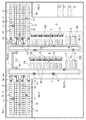
図1に示すように、物品処理システムとしての物流倉庫SUは、物品処理部としての自動倉庫設備1が一対設けられている。一方の自動倉庫設備1(以下、第1自動倉庫設備1aという。)は、物品運搬用のトラックの発着場が設けられたプラットフォーム2に隣接する位置に、また、他方の自動倉庫設備1(以下、第2自動倉庫設備1bという。)は、第1自動倉庫設備1aに隣接する位置に設けられている。
[First Embodiment]
Hereinafter, a first embodiment of an article processing system of the present invention will be described with reference to the drawings.
As shown in FIG. 1, a distribution warehouse SU as an article processing system is provided with a pair of
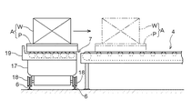
図2にも示すように、第1自動倉庫設備1aは、スタッカークレーン11が備えられた物品保管用の自動倉庫3、プラットフォーム2を経由して外部から自動倉庫設備1aに搬入される搬入物品及びプラットフォーム2を経由して自動倉庫設備1aから外部に搬出される搬出物品を搬送する複数の搬出入コンベヤ4、これらの搬出入コンベヤ4と自動倉庫3の入出庫口5との間に亘る環状の第1走行経路L1に沿って設けられた一対の案内レール6、案内レール6に案内されながら第1走行経路L1に沿って時計回りに走行して物品A(実際には、パレットP及びそれに載置された荷W、又は、パレットPのみ)を搬送する複数の搬送車7、搬送車にて搬送される物品Aの荷Wを構成する複数のパッケージのうち必要な数だけ取り出して、それらのパッケージを搬出用のコンテナボックスや段ボールケースに詰め合わせるピッキング作業を行う複数のピッキング箇所8等を備えている。
As shown in FIG. 2, the first
自動倉庫3は、物品Aを収納する収納部9が縦横に複数並設された収納棚10が複数備えられている。各収納棚10は、収納部9における物品出し入れ口が対向するように、複数の対を為す状態で配置されており、各対の収納棚10の間には、スタッカークレーン11が走行移動するための走行用空間が設けられ、この走行用空間の床面側にはスタッカークレーン11を走行案内する走行レール12が敷設されている。
The
ちなみに、本実施形態では、3対6個の収納棚10が設置されており、3台のスタッカークレーン11が、各対の収納棚10に対応する走行用空間を走行レール12に案内されながら走行移動自在に設けられている。
Incidentally, in this embodiment, three to six
自動倉庫3の入出庫口5には、入庫コンベヤ13及び出庫コンベヤ14が設けられている。説明を加えると、入庫コンベヤ13及び出庫コンベヤ14は、いずれもローラーコンベヤにて構成されており、案内レール6と、収納棚10の前記案内レール6側の端部との間に設置されている。そして、図外のコンベヤモータの回転駆動により搬送面上に載置された物品Aを、それぞれのコンベヤについて設定された搬送方向に搬送するようになっている。
A loading /
各走行レール12の案内レール6側の端部付近には、入出庫コントローラH1が設置されている。入出庫コントローラH1は、後述する管理制御装置Hと通信可能に接続(図6参照)されており、管理制御装置Hが指令する入出庫指令に基づいて、対応するスタッカークレーン11並びに入庫コンベヤ13及び出庫コンベヤ14の作動を制御する。
An entrance / exit controller H <b> 1 is installed in the vicinity of the end of each traveling
入庫コンベヤ13は、これに対応した停止位置に停止する搬送車7にて入庫用搬送開始位置13sに載置された物品Aを、入庫用搬送終了位置13eまで搬送する。そして、入庫用搬送終了位置13eまで搬送された物品Aは、スタッカークレーン11にて移載されて収納棚10の収納部9に収納される。また、出庫コンベヤ14は、スタッカークレーン11にて出庫用搬送開始位置14sに載置された物品Aを、出庫用搬送終了位置14eまで搬送する。そして、出庫用搬送終了位置14eまで搬送された物品Aは、その出庫コンベヤ14に対応した停止位置に停止する搬送車7にて移載されて搬出入コンベヤ4の位置する箇所まで搬送される。
The
搬出入コンベヤ4は、ローラーコンベヤにて構成されており、搬送方向が搬入用搬送方向と搬出用搬送方向とに、他の搬出入コンベヤ4とは独立に、切り換え自在に構成されている。これらの複数の搬出入用コンベヤ4の夫々の搬送作動を一括して制御する搬出入コントローラH2が設けられている。
The carry-in / out
搬出入コントローラH2は、管理制御装置Hと通信可能に接続されており(図6参照)、管理制御装置Hが指令する搬出入指令に基づいて、複数の搬出入用コンベヤ4の夫々について搬送方向の切り換えや搬送作動の開始及び停止を制御するように構成されている。具体的には、管理制御装置Hが搬出物品及び搬入物品の多寡に応じて各搬出入コンベヤ4の搬送方向情報を含む搬出入指令を搬出入コントローラH2に指令すると、搬出入コントローラH2が各搬出入コンベヤ4を指令された搬送方向にて搬送作動させるように構成されている。
The carry-in / out controller H2 is communicably connected to the management control device H (see FIG. 6), and based on the carry-in / out command instructed by the management control device H, the conveyance direction for each of the plurality of carry-in / out
搬出入コンベヤ4の案内レール6側の端部では、その搬出入コンベヤ4に対応する停止位置に停止する搬送車7との間で物品Aの移載が行われ、搬出入コンベヤ4のプラットフォーム2側の端部では、フォークリフト等との間で物品Aの移載が行われる。
At the end of the carry-in / out
そして、搬出入コントローラH2には、警報用の回転灯21が接続されている(図6参照。)。搬出入コントローラH2は、複数の搬出入コンベヤ4の夫々について制御指令通りの搬送作動を行っているか否かを監視し、制御指令通りの搬送作動を行っていない搬出入コンベヤ4を検出した場合には、その搬出入コンベヤ4の作動を停止させるとともに、搬出入用コンベヤ4に異常が発生したとして、作業員にその異常の発生を警報するべく、回転灯21を作動させるように構成されている。
The alarm
つまり、搬出入コントローラH2は、搬出入用コンベヤ4の異常を検出する異常検出手段として機能しており、また、回転灯21は、搬出入コントローラH2にて異常が検出されると警報する警報手段として機能している。
That is, the carry-in / out controller H2 functions as an abnormality detection means for detecting an abnormality in the carry-in / out
ピッキング箇所8の夫々には、3つの一方向直線コンベヤを組み合わせて構成されたコの字コンベヤ15が設けられている。コの字コンベヤ15は、搬送作動の開始及び停止を手動操作により指令できるように構成されている。
Each
ピッキング箇所8におけるピッキング作業について説明を加えると、コの字コンベヤ15に関して案内レール6と反対側に位置するピッキング作業者が、自動倉庫3より出庫され搬送車7にてコの字コンベヤ15の搬送入口15sまで搬送された物品Aをピッキング作業が行い易い位置に位置させるべく、コの字コンベヤ15の搬送作動を開始及び停止させる。そして、コの字コンベヤ15上の物品Aからピッキング伝票に示されるピッキング対象物品を指定数量だけ取り出し、パレットPに載せられた搬出用のコンテナボックスや段ボールケースに詰めるとともに、物品Aをコの字コンベヤ15の搬送出口15eに位置させるべく、コの字コンベヤ15の搬送作動を再開及び停止させる。その後、物品Aは、搬送車7にて自動倉庫3の入出庫口5における入庫コンベヤ13に対応する位置まで搬送され、自動倉庫3に入庫される。
The picking work at the picking
なお、ピッキング箇所8におけるピッキング対象物品は、単一品種の場合と複数品種の場合がある。つまり、上記ピッキング作業におけるピッキング伝票には、複数種類のピッキング対象物品についての夫々の指定数量が示される場合もあり、この場合には、搬送車7にて複数種類の物品Aが順次コの字コンベヤ15の搬送入口15sまで搬送され、搬出用のコンテナボックスや段ボールケースに複数種類の物品Aが詰め合わされることになる。
Note that the picking target article at the picking
ピッキング箇所8にてピッキング伝票に示されたピッキング対象物品の全数が詰められた搬出用のコンテナボックスや段ボールケースは、パレットPに載せられた状態で払い出しコンベヤ16にて、搬出入コンベヤ4付近まで搬送され、搬出入コンベヤ4にて搬出される物品Aと同様に、フォークリフト等によりパレットPごと移載されて、プラットフォーム2に搬送される。
The container box and the cardboard case for unloading in which all the objects to be picked indicated in the picking slip at the
搬送車7は、図3に示すように、車体本体17の下方に設けられ走行レール6に案内される走行車輪18と、車体本体17の上面に設けられた移載用コンベヤ19とを備えている。移載用コンベヤ19は、それに載置された物品Aを搬送車7の進行方向と直行する方向に引き込み又は押し出すことができるように、その搬送方向が切り換え自在に構成されている。
As shown in FIG. 3, the
なお、移載用コンベヤ19の搬送面の床面からの高さは、搬出入コンベヤ4、ピッキング箇所8のコの字コンベヤ15、並びに、入出庫口5の入庫コンベヤ13及び出庫コンベヤ14の各コンベヤの搬送面に略一致した高さとなっており、上記各コンベヤに対応して設定された物品移載用の停止位置に搬送車7が停止した状態で、移載用コンベヤ19と各コンベヤとの間で物品Aを移載できるようになっている。
The height of the transfer surface of the
第2自動倉庫設備1bの構成は、自動倉庫3と案内レール6との位置関係やピッキング箇所8の個数が異なる他は、第1自動倉庫設備1aと略同じ構成であるので、詳しい説明は省略する。
The configuration of the second
そして、各搬送車7の運転を管理する運転制御手段としての管理制御装置Hが、第1自動倉庫設備1aの案内レール6と、第2自動倉庫設備1bの案内レール6との間に位置する箇所に設けられている。
And the management control apparatus H as an operation control means which manages the driving | operation of each
管理制御装置Hは、各搬送車7に対して運転指令を無線信号にて指令し、この運転指令に基づいて、各搬送車7に搭載された車載コントローラが、搬送車7の駆動輪18dの駆動や前記移載用コンベヤ19の搬送作動を制御するように構成されている。
The management control device H commands a driving command to each
この物流倉庫SUは、第1自動倉庫設備1aと第2自動倉庫設備1bの夫々に対して配設されている第1走行経路L1及び第2走行経路L2に存在する搬送車7が、経路変更用中継部としてのトラバーサ部TRを通して、互いに反対側の自動倉庫設備における走行経路に移動できるように構成されている。
The distribution warehouse SU is configured such that the
トラバーサ部TRについて説明を加えると、第1自動倉庫設備1aの第1走行経路L1と第2自動倉庫設備1bの第2走行経路L2との間で搬送車7の車体移動を行う車体移動手段としてのトラバーサ23が床面に設けられている。
The traverser unit TR will be described as a vehicle body moving means for moving the vehicle body of the
搬送車7がこのトラバーサ部TRに設けられた車体移動手段としてのトラバーサ23にて移動されることにより、搬送車7が配設される自動倉庫設備1(例えば、第1自動倉庫設備1a)の走行経路(先の例でいうと、第1走行経路L1)と他の自動倉庫設備1(先の例でいうと、第2自動倉庫設備1b)の走行経路(先の例でいうと、第2走行経路L2)との間での車体移動が行われる。
When the
図4に示すように、トラバーサ23は、第1経路用シフタ24及び第2経路用シフタ26並びにスライドターンテーブル25からなっている。これらはいずれも、夫々に対応して床面に形成されたピット27に埋め込み状態で設けられた基台30と、基台30を図4の紙面左右方向にスライドさせるスライド移動機構を備えている。
As shown in FIG. 4, the
第1経路用シフタ24及び第2経路用シフタ26並びにスライドターンテーブル25の各基台30には、搬送車7の車長程度の長さの一対の移動案内レール36が設けられており、搬送車7を基台30上で停止させた状態で、搬送車7を図4の紙面左右方向に移動させることができるようになっている。なお、スライドターンテーブル25の基台30には、ターンテーブル35が設けられており、搬送車7の向きを180度回転させることができるようになっている。すなわち、スライドターンテーブル25は、搬送車7を横方向にスライド移動させながら、搬送車7の向きを前後方向で反対向きにすることができるようになっている。
Each
第1経路用シフタ24のピット27aとスライドターンテーブル25のピット27bとの間に位置する床面には、第1経路用シフタ24とスライドターンテーブル25との乗り継ぎ時に搬送車7の走行を案内する第1経路側乗り継ぎ用レール37が、また、第2経路用シフタ26のピット27cとスライドターンテーブル25のピット27bとの間に位置する床面には、第2経路用シフタ26とスライドターンテーブル25との乗り継ぎ時に搬送車7の走行を案内する第2経路側乗り継ぎ用レール38が設けられている。なお、各ピット27には、基台30の左右スライド経路に沿って基台30の裏面に形成された図外の案内溝に系合するスライド案内レール40が設けられている。
The floor located between the
第1経路用シフタ24を例に、基台30を左右スライドさせるスライド移動機構について説明を加える。図5に示すように、スライド移動機構は、ピット27の底面に設けられたラック28と、このラック28に歯合するピニオンギヤ29と、基台30に設けられた駆動用モータ31と、基台30の紙面右側端部を検出することで基台30が通常位置に位置することを検出する通常位置検出手段としての通常位置用光センサ32と、基台30の紙面左側端部を検出することで基台30が切換位置に位置することを検出する切換位置検出手段としての切換位置用光センサ33と、管理制御装置Hと通信可能に接続(図6参照)され、管理制御装置Hが指令するスライド指令に基づいて、駆動用モータ31の駆動を制御するスライドコントローラH3とを備えている。
Taking the
そして、管理制御装置Hからスライド指令がスライドコントローラH3に指令されると、スライドコントローラH3は、駆動用モータ31の駆動を開始し、通常位置用光センサ32が基台30が通常位置に位置していることを検出すると、又は、切換位置用光センサ33が基台30が切換位置に位置していることを検出すると、スライドコントローラH3は、駆動用モータ31の駆動を停止する。
When a slide command is commanded from the management control device H to the slide controller H3, the slide controller H3 starts driving the
第1経路用シフタ24の基台30についての通常位置は、図4に示すように、環状の第1走行経路L1内外方向で内側に寄った状態で、基台30における同外側の移動案内レール36aが第1走行経路L1に位置するときの基台30の位置をいうものとし、第1経路用シフタ24の基台30についての切換位置は、環状の第1走行経路L1内外方向で外側に寄った状態で、基台30における同内側の移動案内レール36bが第1走行経路L1に位置するときの基台30の位置をいうものとする。そして、第1経路用シフタ24の基台30が切換位置に位置すると、基台30における同外側の移動案内レール36aと、前記第1経路側乗り継ぎ用レール37とが同一直線上に位置するようになっている。
As shown in FIG. 4, the normal position of the
第2経路用シフタ25の基台30についての通常位置及び切換位置についても同様である。また、スライドターンテーブル25の基台30についての通常位置及び切換位置については、図4に示す位置、つまり、スライドターンテーブル25の移動案内レール36と、前記第1経路側乗り継ぎ用レール37とが同一直線上に位置する位置を通常位置とし、スライドターンテーブル25の移動案内レール36と、前記第2経路側乗り継ぎ用レール38とが同一直線上に位置する位置を切換位置としている。
The same applies to the normal position and the switching position of the
管理制御装置Hが指令するスライド指令は、切換スライド指令及び復帰スライド指令があり、第1経路用シフタ24のスライドコントローラH3に対して切換スライド指令が指令されると、スライドコントローラH3は、第1経路用シフタ24の基台30を切換位置に位置させるべく、また、復帰スライド指令が指令されると、スライドコントローラH3は、第1経路用シフタ24の基台30を通常位置に位置させるべく、通常位置用光センサ32及び切換位置用光センサ33の検出情報に基づいて、駆動用モータ31の作動を制御する。
The slide commands commanded by the management control device H include a switching slide command and a return slide command. When the switching slide command is commanded to the slide controller H3 of the
したがって、切換スライド指令が指令されると、第1経路用シフタ24は切換位置に位置する状態となり、復帰スライド指令が指令されると、第1経路用シフタ24は通常位置に位置する状態(図4に示す状態)となる。第2経路用シフタ26のスライドコントローラH3に対して切換スライド指令及び復帰スライド指令が指令される場合も同様である。
Therefore, when the switching slide command is instructed, the
スライドターンテーブル25のスライドコントローラH3に対して切換スライド指令が指令されると、スライドターンテーブル25の基台30は切換位置に位置する状態になり、復帰スライド指令が指令されると、スライドターンテーブル25の基台30は通常位置に位置する状態(図4に示す状態)にとなる。
When a switching slide command is commanded to the slide controller H3 of the
第2自動倉庫設備1bについても、第1自動倉庫設備1aと同様の構成となっており、図6に示すように、管理制御装置Hには、第1自動倉庫設備1a及び第2自動倉庫設備1bの各コントローラが通信可能に接続されている。
The second
管理制御装置Hは、複数の自動倉庫設備1の夫々に配設されている搬送車7をそれが配設されている自動倉庫設備1についての搬出入コンベヤ4と入出庫口5との間で物品Aを搬送すべく、搬送車7の運転を制御する通常運転と、複数の自動倉庫設備1の夫々に配設されている搬送車7をそれが配設されている自動倉庫設備1についての入出庫口5と他の自動倉庫設備1についての搬出入コンベヤ4との間で物品Aを搬送する、または、それが配設されている自動倉庫設備1についての搬出入コンベヤ4と他の自動倉庫設備1についての入出庫口5との間で物品Aを搬送すべく、搬送車7の運転を制御する経路切り換え運転とに変更自在に構成されている。
The management control device H is arranged between the loading /
説明を加えると、管理制御装置Hは、通常運転では、第1自動倉庫設備1aに配設されている搬送車7を第1自動倉庫設備1aについての搬出入コンベヤ4と入出庫口5との間で物品Aを搬送すべく、また、第2自動倉庫設備1bに配設されている搬送車7を第2自動倉庫設備1bについての搬出入コンベヤ4と入出庫口5との間で物品Aを搬送すべく、搬送車7の運転を制御する。
If it adds explanation, management control device H will carry out
つまり、通常運転では、第1走行経路L1から第2走行経路L2との間の車体移動は行われず、それぞれの搬送車7は、それが配設されている走行経路に沿って、巡回走行することで、第1自動倉庫設備1aの搬出入コンベヤ4と入出庫口5との間、及び、第2自動倉庫設備1bの搬出入コンベヤ4と入出庫口5との間で物品Aを搬送する。
That is, in normal operation, the vehicle body is not moved between the first travel route L1 and the second travel route L2, and each
一方、管理制御装置Hは、経路切り換え運転では、第1自動倉庫設備1aに配設されている搬送車7を第1自動倉庫設備1aについての入出庫口5と第2自動倉庫設備1bについての搬出入コンベヤ4との間で物品Aを搬送する、または、第1自動倉庫設備1aについての搬出入コンベヤ4と第2自動倉庫設備1bについての入出庫口5との間で物品Aを搬送すべく、搬送車7の運転を制御する。
On the other hand, in the route switching operation, the management control device H moves the
つまり、経路切り換え運転では、必要に応じて、第1走行経路L1と第2走行経路L2との間の車体移動が行われ、それぞれの搬送車7は、第1走行経路L1から第2走行経路L2へ、又は、第2走行経路L2から第1走行経路L1へ移動することで、第1自動倉庫設備1aの入出庫口5と第2自動倉庫設備1bの搬出入コンベヤ4との間で物品Aを搬送し、また、第2自動倉庫設備1bの入出庫口5と第1自動倉庫設備1aの搬出入コンベヤ4との間で物品Aを搬送する。
That is, in the route switching operation, the vehicle body is moved between the first travel route L1 and the second travel route L2 as necessary, and each
本実施形態では、図6に示すように、管理制御装置Hには、通常運転と経路切り換え運転に切り換える指令を指令する手動式の入力手段としての運転切換スイッチ20が設けられている。運転切換スイッチ20は、通常運転を指令する通常運転指令状態と経路切り換え運転を指令する切換運転指令状態とに切り換え操作自在なトグルスイッチにて構成されている。
In the present embodiment, as shown in FIG. 6, the management control device H is provided with an
そして、管理制御装置Hが通常運転で動作している場合に、第1自動倉庫設備1aの搬出入コンベヤ4の何れかに異常が発生したときや、第2自動倉庫設備1bの搬出入コンベヤ4の何れかに異常が発生したときには、対応する自動倉庫設備1の回転灯21の警報作動によりその異常を認識した作業者が運転切換スイッチ20を切り換え操作して切換運転指令状態にして管理制御装置Hを経路切り換え運転で動作させることで、物流倉庫SUの物品処理能力を極力維持することができるようになっている。
When the management control device H is operating in a normal operation, when any abnormality occurs in the carry-in / out
説明を加えると、例えば、第1自動倉庫設備1aの搬出入コンベヤ4の一部又は全部に異常が発生したときには、運転切換スイッチ20を切り換え操作して管理制御装置Hを経路切り換え運転で動作させることにより、第1自動倉庫設備1aの自動倉庫3から出庫した物品Aを、第1自動倉庫設備1aに配設された搬送車Aにて、第1走行経路L1、トラバーサ23、及び、第2走行経路L2を経由して、第2自動倉庫設備1bの搬出入コンベヤ4に搬送して、異常が発生した第1自動倉庫設備1aの搬出入コンベヤ4に代えて、正常動作している第2自動倉庫設備1bの搬出入コンベヤ4にて物品Aを搬出することができ、もって、第1自動倉庫設備1aの自動倉庫3から出庫された物品Aを第2自動倉庫設備1bの搬出入コンベヤ4にて搬出することができる。
For example, when an abnormality occurs in a part or all of the carry-in / out
また、異常が発生した第1自動倉庫設備1aの搬出入コンベヤ4に代えて、正常動作している第2自動倉庫設備1bの搬出入コンベヤ4にて第1自動倉庫設備1aの自動倉庫3に入庫すべき物品Aを搬入し、第1自動倉庫設備1aに配設された搬送車Aを、トラバーサ23、及び、第2走行経路L2を経由して第2自動倉庫設備1bの搬出入コンベヤ4まで走行させて、当該物品Aを当該搬送車7にて第2走行経路L2、トラバーサ23、及び、第1走行経路L1を経由して、第1自動倉庫設備1aの入庫コンベヤ13に搬送することができ、もって、第2自動倉庫設備1bの搬出入コンベヤ4にて搬入された物品Aを第1自動倉庫設備1aの自動倉庫3に入庫することができる。
Further, instead of the carry-in / out
さらに、第1自動倉庫設備1aの自動倉庫3における入庫コンベヤ13の一部又は全部に異常が発生したときには、運転切換スイッチ20を切り換え操作して管理制御装置Hを経路切り換え運転で動作させることにより、第1自動倉庫設備1aに配設された搬送車Aにて、第1自動倉庫設備1aの搬出入コンベヤ4から、第1走行経路L1、トラバーサ23、及び、第2走行経路L2を経由して、第2自動倉庫設備1bの入庫コンベヤ13に搬送することができ、もって、第1自動倉庫設備1aの搬出入コンベヤ4にて搬入された物品Aを第2自動倉庫設備1bの自動倉庫3に入庫することができる。
Further, when an abnormality occurs in a part or all of the
また、第1自動倉庫設備1aの自動倉庫3における出庫コンベヤ14の一部又は全部に異常が発生したときには、運転切換スイッチ20を切り換え操作して管理制御装置Hを経路切り換え運転で動作させることにより、第1自動倉庫設備1aに配設された搬送車Aを、トラバーサ23、及び、第2走行経路L2を経由して第2自動倉庫設備1bの出庫コンベヤ14まで走行させて、第2自動倉庫設備1bの自動倉庫3から物品Aを出庫し、当該物品Aを当該搬送車7にて第2走行経路L2、トラバーサ23、及び、第1走行経路L1を経由して、第1自動倉庫設備1aの搬出入コンベヤ4に搬送することができ、もって、第2自動倉庫設備1bの自動倉庫3から出庫した物品Aを第1自動倉庫設備1aの搬出入コンベヤ4にて搬出することができる。
Further, when an abnormality occurs in a part or all of the
上記各例では、第1自動倉庫設備1aの搬出入コンベヤ4又は入庫コンベヤ13若しくは出庫コンベヤ14に異常が発生した場合について説明したが、第2自動倉庫設備1bの搬出入コンベヤ4又は入庫コンベヤ13若しくは出庫コンベヤ14に異常が発生した場合も同様に、運転切換スイッチ20を切り換え操作して管理制御装置Hを経路切り換え運転で動作させることにより、第2自動倉庫設備1bに配設された搬送車7は、第2自動倉庫設備の入庫コンベヤ13若しくは出庫コンベヤ14と第1自動倉庫設備1aについての搬出入コンベヤ4との間で物品Aを搬送する、又は、第2自動倉庫設備1bについての搬出入コンベヤ4と第1自動倉庫設備1aについての入庫コンベヤ13若しくは出庫コンベヤ14との間で物品Aを搬送するように制御される。
In each of the above examples, the case where an abnormality has occurred in the carry-in / out
以下に、管理制御装置Hの経路切り換え運転における制御動作について、第1自動倉庫設備1aにおける搬出入コンベヤ4に異常が発生した場合において、第1自動倉庫設備1aの自動倉庫3から出庫した物品Aを第2自動倉庫設備1bから搬出するときを例に、図7のフローチャートに基づいて説明する。
In the following, regarding the control operation in the path switching operation of the management control device H, when an abnormality occurs in the carry-in / out
ステップ#A1で、搬送車7を第1走行経路L1に沿って、今回の搬出対象の物品Aが収納されている収納棚10についての出庫コンベヤ14(以下、対象出庫コンベヤ14という。)に対応した停止位置まで走行させる。
In step # A1, along the first travel route L1, the
ステップ#A2で、対象出庫コンベヤ14についての入出庫コントローラH1に対して出庫指令を指令する。この出庫指令に基づいて、入出庫コントローラH1が、スタッカークレーン11の作動を制御して、対象出庫コンベヤ14の出庫用搬送開始位置14sに物品Aを搬送させ(ステップ#A3)、対象出庫コンベヤ14の作動を制御して、出庫用搬送終了位置14eまで物品Aを搬送させる(ステップ#A4)。
In step # A2, a delivery command is issued to the delivery controller H1 for the
ステップ#A5で、搬送車7が対象出庫コンベヤ14に対応した停止位置に停止した状態で、搬送車7の移載用コンベヤ19及び対象出庫コンベヤ14の双方を搬送作動させることにより、搬送車7に物品Aが載置された状態とする。
In step # A5, in a state where the
ステップ#A6で、搬送車7を第1走行経路L1に沿って第1経路用シフタ24まで走行させる。このとき、第1経路用シフタ24が切換位置であって通常位置でなければ、第1経路用シフタ24のスライドコントローラH3に復帰スライド指令を指令して、第1経路用シフタ24を通常位置に復帰させることで、搬送車7は通常位置の第1経路用シフタ24上に位置することができるようになっている。なお、トラバーサ23における他の基台30が切換位置になっている場合には、第1経路用シフタ24の場合と同様に、対応するスライドコントローラH3に復帰スライド指令を指令して通常位置に位置させる。
In step # A6, the
ステップ#A7で、第1経路用シフタ24のスライドコントローラH3に切換スライド指令を指令する。搬送車7はステップ#A6で第1走行経路L1から通常位置の第1経路用シフタ24に載り移るので、第1経路用シフタ24が切換位置までスライド移動すると、搬送車7は、第1走行経路L1内外方向で外側の移動案内レール36aに載った状態で、第1経路側乗り継ぎ用レール37に対応した走行経路に位置する状態となる。
In step # A7, a switching slide command is commanded to the slide controller H3 of the
ステップ#A8で、搬送車7を前進走行させて、第1経路側乗り継ぎ用レール37に案内された状態で、通常位置となっているスライドターンテーブル25まで走行させる。
In Step # A8, the
搬送車7がスライドターンテーブル25に完全に乗り移った後、ステップ#A9で、スライドターンテーブル25のスライドコントローラH3に切換スライド指令を指令する。これにより、スライドターンテーブル25の基台30が第2走行経路L2側に切換位置まで横移動しながら、ターンテーブル35が時計回りに180度回転して、搬送車7は、第2走行経路L2における走行方向を向いた状態で第2経路側乗り継ぎ用レール38に対応した走行経路に位置する状態となる。
After the
ステップ#A10で、搬送車7を前進走行させて、第2経路側乗り継ぎ用レール38に案内された状態で、通常位置となっている第2経路用シフタ26まで走行させる。
In step # A10, the
ステップ#A11で、第2経路用シフタ26のスライドコントローラH3に切換スライド指令を指令する。搬送車7はステップ#A10でスライドターンテーブル25から通常位置の第2経路用シフタ26に載り移るので、第2経路用シフタ26が切換位置までスライド移動すると、搬送車7は第2走行経路L2内外方向で外側の移動案内レール36aに載った状態で、第2走行経路L2に位置する状態となる。
In step # A11, a switching slide command is commanded to the slide controller H3 of the
ステップ#A12で、搬送車7を第2走行経路L2に沿って、物品Aの搬出に引き当てられた搬出入コンベヤ4(以下、対象搬出入コンベヤ4という。)に対応した停止位置まで走行させる。
In step # A12, the
ステップ#A13で、搬出入コンベヤ4の搬出入コントローラH2に搬出入指令を指令し、対象搬出入コンベヤ4を搬出用搬送方向で搬送作動させる。
In step # A13, a carry-in / out command is commanded to the carry-in / out controller H2 of the carry-in / out
ステップ#A14で、搬送車7が対象搬出入コンベヤ4に対応した停止位置に停止した状態で、搬送車7の移載用コンベヤ19を搬送作動させることで、移載用コンベヤ19及び対象搬出入コンベヤ4の双方の搬送作動により、搬送車7に載置されていた物品Aが搬出される。
In step # A14, the
以上の通り、第1自動倉庫設備1aにおける搬出入コンベヤ4に異常が発生した場合でも、管理制御装置Hを経路切り換え運転で動作させることで、第1自動倉庫設備1aの自動倉庫3から出庫した物品Aを第2自動倉庫設備1bから搬出することで、物流倉庫SUの物品処理能力を極力維持することができるようになっている。
As described above, even when an abnormality occurs in the carry-in / out
しかも、トラバーサ部TRには、第1自動倉庫設備1aの第1走行経路L1と第2自動倉庫設備1bの第2走行経路L2との間で搬送車7の車体移動を行うトラバーサ23が備えられているので、搬送車Aに走行経路を変更するための特段の機能を備えさせなくても、管理制御装置Hを経路切り換え運転で動作させることができる。
Moreover, the traverser unit TR is provided with a
〔第2実施形態〕
次に、本発明の物品処理システムの第2実施形態を図面に基づいて説明する。第2実施形態は、管理制御装置Hの構成が第1実施形態と異なる他は同様の構成であるので、第1実施形態と一致する点については説明を省略し、第1実施形態と相違する点について説明する。
[Second Embodiment]
Next, a second embodiment of the article processing system of the present invention will be described based on the drawings. The second embodiment is the same as the first embodiment except that the configuration of the management control device H is different from that of the first embodiment. Therefore, the description of points that are the same as those of the first embodiment is omitted, and is different from the first embodiment. The point will be described.
本実施形態では、管理制御装置Hは、第1自動倉庫設備1aの搬出入コンベヤ4又は第2自動倉庫設備1bの搬出入コンベヤ4にて、第1自動倉庫設備1a及び第2自動倉庫設備1bにおいて分配保管すべき特定の物品Aが搬入された場合には、その搬出入コンベヤ4が配設される自動倉庫設備1における入出庫口5と他の自動倉庫設備1における入出庫口5とに特定の物品Aを分配搬送すべく、経路切り換え運転を行うように構成されている。
In the present embodiment, the management control device H uses the first
説明を加えると、ある物品Aを第1自動倉庫設備1a及び第2自動倉庫設備1bの何れか一方にだけ保管していると、物品Aが保管されている自動倉庫設備1が故障した場合には、自動倉庫3に保管している物品Aを出庫乃至搬出できなくなるリスクがあるが、このリスクを分散するために、特定の物品Aについては、第1自動倉庫設備1a及び第2自動倉庫設備1bの双方において保管するようになっている。
In other words, if an article A is stored only in one of the first
そして、作業者が運転切換スイッチ20を指令操作して、管理制御装置Hが通常運転から経路切り換え運転に切り換わってから、特定の物品Aが、何れかの自動倉庫設備1の搬出入コンベヤ4にて搬入された場合には、その搬出入コンベヤ4が配設される自動倉庫設備1における入出庫口5と他の自動倉庫設備1における入出庫口5とに特定の物品Aを分配搬送するようになっている。
Then, after the operator operates the
以下に、管理制御装置Hの経路切り換え運転における制御動作について、第1自動倉庫設備1aにおける搬出入コンベヤ4にて物品Aが搬入される場合を例に、図8のフローチャートに基づいて説明する。
Below, the control operation | movement in the path | route switching operation of the management control apparatus H is demonstrated based on the flowchart of FIG. 8 for the case where the articles | goods A are carried in by the carrying in / out
第1自動倉庫設備1a及び第2自動倉庫設備1bの双方において分配保管すべき物品Aが第1自動倉庫設備1aにおける搬出入コンベヤ4にて搬入されると、まず、ステップ#B1で搬入数を計数する搬入数カウンタiがリセットされる。ステップ#B2で、第1自動倉庫設備1aに配設された搬送車7を第1自動倉庫設備1aの複数の搬出入コンベヤ4のうち、物品Aが搬入されたコンベヤに対応する停止位置まで走行させる。ステップ#B3で、当該搬出入コンベヤ4を搬入用搬送方向で搬送作動させ、搬送車7の移載用コンベヤ19を引き込み方向に搬送作動させて、搬送車7に物品Aを載置させる。ステップ#B4で、搬入数カウンタiの値を参照し、偶数であるか奇数であるかを判別する。
When the article A to be distributed and stored in both the first
搬入数カウンタiの値が奇数であれば、ステップ#B5で搬送車7を第1走行経路L1に沿って第1自動倉庫設備1aの入出庫口5まで走行させ、ステップ#B6で第1自動倉庫設備1aの入出庫コントローラH1に入庫指令を指令する。この入庫指令により物品Aが搬送車7の移載用コンベヤ19から入庫コンベヤ13の入庫用搬送開始位置13aに押し出されて、入庫コンベヤ13により入庫用搬送終了位置13eまで搬送され、スタッカークレーン11により収納棚10における所定の収納部9に収納される。
If the value of the carry-in counter i is an odd number, in step # B5, the
搬出入カウンタiの値が偶数であれば、ステップ#B7で搬送車7を、トラバーサ23を利用して、第1走行経路L1及び第2走行経路L2に沿って第2自動倉庫設備1bの入出庫口5まで走行させ、ステップ#B8で第2自動倉庫設備1bの入出庫コントローラH1に入出庫指令を指令する。この入庫指令により物品Aが、搬送車7の移載用コンベヤ19から入庫コンベヤ13の入庫用搬送開始位置13aに押し出されて、入庫コンベヤ13により入庫用搬送終了位置13eまで搬送され、スタッカークレーン11により収納棚10における所定の収納部9に収納される。
If the value of the carry-in / out counter i is an even number, in step # B7, using the
ステップ#B6又はステップ#B8にて物品Aが自動倉庫3に入庫されると、ステップ#B9で搬入数カウンタiの値がインクリメントされたのち、ステップ#B10で、通常運転への切換指令の有無が判別され、通常運転への切換指令があれば、経路切り換え運転を終了する。通常運転への切換指令がなければ、ステップ#B2に戻って、次に搬出入コンベヤ4にて搬入される物品Aを、第1自動倉庫設備1aの自動倉庫3又は第2自動倉庫設備1bの自動倉庫3に入庫するための処理が実行される。
When the article A is received in the
このように、第1自動倉庫設備1aの搬出入コンベヤ4にて搬入される物品Aのうち奇数個目の物品Aは第1自動倉庫設備1aの自動倉庫3に入庫され、偶数個目の物品Aは第2自動倉庫設備1bの自動倉庫3に入庫される。
As described above, the odd-numbered articles A among the articles A carried in by the carry-in / out
このようにすることで、双方の自動倉庫設備1の搬出入コンベヤ4にて当該特定の物品Aをわざわざ分散して搬入することなく、一方の自動倉庫設備1の搬出入コンベヤ4にて物品Aを搬入して、物品Aを第1自動倉庫設備1a及び第2自動倉庫設備1bにおける自動倉庫3に分散保管することができるので、特定の物品Aを第1自動倉庫設備1a及び第2自動倉庫設備1bの各自動倉庫3に分散保管するに当たっての物品Aの搬入作業は、何れかの自動倉庫設備1の搬出入コンベヤ4に当該物品Aを搬入するだけの簡単なものとなる。
By doing in this way, the goods A are carried out by the carry-in / out
このように、本実施形態の物品処理システムであると、簡単な搬入作業により特定の物品Aを第1自動倉庫設備1a及び第2自動倉庫設備1bにおける各自動倉庫3に分散保管することができる。
Thus, with the article processing system of this embodiment, a specific article A can be distributed and stored in each
〔第3実施形態〕
次に、本発明の物品処理システムの第3実施形態を図面に基づいて説明する。第3実施形態は、管理制御装置Hの構成が第1実施形態と異なる他は同様の構成であるので、第1実施形態と一致する点については説明を省略し、第1実施形態と相違する点について説明する。
[Third Embodiment]
Next, a third embodiment of the article processing system of the present invention will be described with reference to the drawings. The third embodiment is the same as the first embodiment except that the configuration of the management control device H is different from that of the first embodiment. Therefore, the description of points that are the same as those of the first embodiment is omitted, and is different from the first embodiment. The point will be described.
本実施形態では、管理制御装置Hは、第1物品処理部1a及び第2物品処理部1bにおける自動倉庫3についての物品収納率を管理して、それら自動倉庫における物品収納率の偏りを抑制すべく経路切り換え運転を行うように構成されている。
In the present embodiment, the management control device H manages the article storage rate for the
説明を加えると、自動倉庫における物品収納率に偏りがあると以下のような不都合が生じる。例えば、同一種の物品Aが第1自動倉庫1a及び第2自動倉庫1bの双方の自動倉庫3に保管されており、これらの自動倉庫3の収納容量が同等であるとすると、第1自動倉庫設備1aにおける自動倉庫3の物品Aの収納率が、第2自動倉庫設備1bの自動倉庫3の収納率より小さいと、第1自動倉庫1a及び第2自動倉庫設備1bの双方から並行して物品Aを搬出する場合に、第1自動倉庫設備1aにおける自動倉庫3の物品Aの全数が搬出された後は、第2自動倉庫設備1bにおける自動倉庫3のみから物品Aが搬出されることになり、搬出効率が低下する。
In addition, if there is a bias in the article storage rate in the automatic warehouse, the following inconvenience occurs. For example, if the same kind of article A is stored in the
また、第1自動倉庫設備1aにおける自動倉庫3の物品Aの収納率が、第2自動倉庫設備1bの自動倉庫3のそれより小さいと、これらの自動倉庫3の各収納容量が同等であることから、第1自動倉庫設備1aにおける自動倉庫3の空き容量が、第2自動倉庫設備1bの自動倉庫3の空き容量より大きくなるので、物品Aを第1自動倉庫1a及び第2自動倉庫1bに並行処理により搬入する場合に、第2自動倉庫設備1bの自動倉庫3が収納限界に達した後は、第1自動倉庫1aにのみ物品Aが搬入されることになり、搬入効率が低下する。
Further, if the storage rate of the article A of the
そこで、本実施形態では、上述のように、第1物品処理部1a及び第2物品処理部1bにおける自動倉庫3についての物品収納率を管理して、経路切り換え運転を行うことで、それら自動倉庫における物品収納率の偏りを抑制して、高い搬出入効率を維持できるようにしている。
Thus, in the present embodiment, as described above, the
具体的には、管理制御装置Hが、搬出入コンベヤ4における搬出入処理がない待機期間中に収納率管理処理を実行して、第1物品処理部1a及び第2物品処理部1bにおける自動倉庫3についての物品収納率をチェックし、許容値以上の差が存在していれば、その差を是正すべく、経路切り換え運転を行って、第1自動倉庫設備1aの自動倉庫3と第2自動倉庫設備1bの自動倉庫3との間で物品Aの移し替えを行っている。
Specifically, the management control device H executes a storage rate management process during a standby period when there is no carry-in / out process in the carry-in / out
以下に、管理制御装置Hの収納率管理処理における制御動作について、図9及び図10のフローチャートに基づいて説明する。なお、説明を分かり易くするため、本実施形態の物流倉庫SUでは一種類の物品Aのみが処理されるものとし、管理制御装置Hは、この種類の物品Aについての収納率を管理するものとする。 Hereinafter, the control operation in the storage rate management process of the management control device H will be described based on the flowcharts of FIGS. 9 and 10. For easy understanding, it is assumed that only one type of article A is processed in the distribution warehouse SU of the present embodiment, and the management control device H manages the storage rate for this type of article A. To do.
管理制御装置Hは、収納率管理処理において、図9のフローチャートに示すように、ステップ#C1で、第1自動倉庫設備1aにおける自動倉庫3についての物品Aの物品収納率R1を算出する。物品収納率R1は、初期値がゼロの入庫数カウンタに基づいて算出される。
In the storage ratio management process, the management control device H calculates the article storage ratio R1 of the article A for the
すなわち、第1自動倉庫設備1aの自動倉庫3についての入庫数カウンタを、自動倉庫3に物品Aを入庫する場合には入庫数に応じてインクリメントし、自動倉庫3から物品Aを出庫する場合には出庫数に応じてデクリメントすることで、自動倉庫3に収納されている物品Aの個数を把握するようにし、第1自動倉庫設備1aの自動倉庫3についての入庫数カウンタの値と、第1自動倉庫設備1aの自動倉庫3の収納容量を表す値との比を、第1自動倉庫設備1aにおける自動倉庫3についての物品収納率R1としている。
In other words, the receipt counter for the
ステップ#C2で、ステップ#C1と同様に、第2自動倉庫設備1bの自動倉庫3についての入庫数カウンタの値に基づいて、第2自動倉庫設備2aにおける自動倉庫3についての物品Aの物品収納率R2を算出する。
In step # C2, as in step # C1, based on the value of the warehousing number counter for the
ステップ#C3で、ステップ#C1で算出した第1自動倉庫設備1aの自動倉庫3についての物品収納率R1及びステップ#C2で算出した第2自動倉庫設備1bの自動倉庫3について物品収納率R2の平均収納率ABRを算出する。
In step # C3, the article storage rate R1 for the
ステップ#C4及びステップ#C5の処理で、物品収納率R1と平均収納率ABRとの差又は物品収納率R2と平均収納率ABRとの差の少なくとも一方が対平均偏差判別用閾値Rthよりも大きければ、第1自動倉庫設備1aの自動倉庫3及び第2自動倉庫設備1bの自動倉庫3における物品収納率に偏りが存在すると判別して、その偏りを是正すべく、ステップ#C6の収納率平準化処理を実行する。物品収納率R1と平均収納率ABRとの差及び物品収納率R2と平均収納率ABRとの差の双方が対平均偏差判別用閾値Rth以下であれば、収納率平準化処理を実行することなく、収納率管理処理を終了する。
In the processing of Step # C4 and Step # C5, at least one of the difference between the article storage rate R1 and the average storage rate ABR or the difference between the article storage rate R2 and the average storage rate ABR is larger than the threshold value Rth for determining the average deviation. For example, it is determined that there is a bias in the article storage rate in the
次に、収納率管理処理において、第1自動倉庫設備1aの自動倉庫3及び第2自動倉庫設備1bの自動倉庫3における物品収納率に偏りが存在すると判別されたときに実行される収納率平準化処理について、図10に示すフローチャートに基づいて説明する。
Next, in the storage rate management processing, the storage rate leveling executed when it is determined that there is a bias in the article storage rates in the
まず、ステップ#D1で、第1自動倉庫設備1aの自動倉庫3か第2自動倉庫設備の自動倉庫3の何れの物品収納率が高いかを判別する。判別結果により、ステップ#D2〜ステップ#D7の処理又はステップ#D8〜ステップ#D13の処理が選択的に実行される。
First, in step # D1, it is determined which item storage rate is higher in the
つまり、第1自動倉庫設備1aの自動倉庫3についての物品収納率R1が、第2自動倉庫設備1bの自動倉庫3についての物品収納率R2よりも高い場合は、ステップ#D2〜ステップ#D7の処理が実行されることにより、物品収納率R1が低下し、同時に、物品収納率R2が上昇することで、物品収納率の偏りが是正され、第2自動倉庫設備1bの自動倉庫3についての物品収納率R2が、第1自動倉庫設備1aの自動倉庫3についての物品収納率R1よりも高い場合は、ステップ#D8〜ステップ#D13の処理が実行されることにより、物品収納率R2が低下し、同時に、物品収納率R1が上昇することで、物品収納率の偏りが是正される。
That is, when the article storage rate R1 for the
以下の説明では、第1自動倉庫設備1aの自動倉庫3についての物品収納率R1が、第2自動倉庫設備1bの自動倉庫3についての物品収納率R2よりも高い場合に実行されるステップ#D2〜ステップ#D7の処理について説明し、ステップ#D8〜ステップ#D13の処理については説明を省略する。
In the following description, step # D2 is executed when the article storage rate R1 for the
ステップ#D2で、第1自動倉庫設備1aにおける自動倉庫3の物品Aをその入出庫口5に出庫するべく、入出庫コントローラH1に対して出庫指令を指令する。これにより、移し替え対象の物品Aが、第1自動倉庫設備1aの出庫コンベヤ14の出庫用搬送終了位置14eまで搬送される。
In step # D2, a command to leave is issued to the loading / unloading controller H1 in order to unload the article A from the
ステップ#D3で、第1自動倉庫設備1aに配設されている搬送車7を、第1走行経路L1に沿って第1自動倉庫設備1aの入出庫口5の該当する出庫コンベヤ14に対応した停止位置まで走行させる。
In step # D3, the
ステップ#D4で、搬送車7が該当する出庫コンベヤ14に対応した停止位置に停止した状態で、搬送車7の移載用コンベヤ19及び対象出庫コンベヤ14の双方を搬送作動させることにより、搬送車7に物品Aが載置された状態とする。
In step # D4, in a state where the
ステップ#D5で、経路切り換え運転により搬送車7の運転を制御して、搬送車7を、第1自動倉庫設備1aの入出庫口5から、第1走行経路L1、トラバーサ部TR、及び、第2走行経路L2を経て、第2自動倉庫設備1bの入出庫口5まで走行させる。経路切り換え運転における、トラバーサ23の作動の制御内容については、第1実施形態と同様であるので、ここでの説明は省略する。
In step # D5, the operation of the
ステップ#D6で、搬送車7に載置されている物品Aを第2自動倉庫設備1bの自動倉庫3に入庫するべく、第2自動倉庫設備1bの入出庫口5における該当する入庫コンベヤ13に対応した停止位置に搬送車7が停止した状態で入庫指令を指令する。これにより、この入庫指令により物品Aが搬送車7の移載用コンベヤ19から入庫コンベヤ13の入庫用搬送開始位置13sに押し出されて、入庫コンベヤ13により入庫用搬送終了位置13eまで搬送され、スタッカークレーン11により収納棚10における所定の収納部9に収納される。
In step # D6, in order to store the article A placed on the
ステップ#D7で、第1自動倉庫設備1aの自動倉庫3についての物品収納率R1と平均収納率ABRとの差の大きさが対平均偏差判別用閾値Rth以下であるかどうかが判別され、対平均偏差判別用閾値Rthより大きければ、未だに物品収納率の偏りが適正な状態まで是正されていないとして、収納率平準化処理が継続される。第1自動倉庫設備1aの自動倉庫3についての物品収納率R1と平均収納率ABRとの差の大きさが対平均偏差判別用閾値Rth以下であれば、物品収納率の偏りが是正されたとして、収納率平準化処理が終了する。
In step # D7, it is determined whether or not the magnitude of the difference between the article storage rate R1 and the average storage rate ABR for the
このように、ステップ#D2〜ステップ#D7までの処理が繰り返し実行されて、第1自動倉庫設備1aの自動倉庫3についての物品収納率R1が低下し、同時に、第2自動倉庫設備1bの自動倉庫3についての物品収納率R2が上昇し、その結果、第1自動倉庫設備1aの自動倉庫3についての物品収納率R1と第2自動倉庫設備1bの自動倉庫3についての物品収納率R2との偏りが是正される。
In this way, the processing from step # D2 to step # D7 is repeatedly executed, the article storage rate R1 for the
以上説明した通り、収納率管理処理及び収納率平準化処理が実行されることにより、第1自動倉庫設備1aの自動倉庫3についての物品収納率R1と第2自動倉庫設備1bの自動倉庫3についての物品収納率R2との偏りが抑制され、各自動倉庫の夫々に満遍なく物品Aが収納された状態とすることができる。
As described above, the storage rate management process and the storage rate leveling process are executed, whereby the article storage rate R1 for the
このように、本実施形態の物品処理システムであると、例えば、大量の物品Aを一時に集中して出庫又は入庫する必要が生じた場合には、第1自動倉庫設備1a及び第2自動倉庫設備1bの夫々から略同数の物品Aを搬出し、又は、第1自動倉庫設備1a及び第2自動倉庫設備1bの夫々に対して略同数の物品Aを搬入して、処理対象の物品Aの全数を一つの自動倉庫設備1にて処理する場合に比べて物品処理に要する時間を短くすることが可能となり、物流倉庫SUにおける処理負荷を第1自動倉庫設備1a及び第2自動倉庫設備1bに分散させて並行して処理することにより、物流倉庫SU全体の処理時間の短縮を図ることができる。
As described above, in the article processing system according to the present embodiment, for example, when it is necessary to concentrate or deliver a large amount of articles A at a time, the first
〔別実施形態〕
以下、別実施形態を列記する。
[Another embodiment]
Hereinafter, other embodiments are listed.
(1)上記第1〜第3実施形態では、手動式の入力手段並びに異常検出手段及び警報手段が設けられたものを例示したが、これに限らず、手動式の入力手段が設けられず、運転制御手段が、異常検出手段の検出情報に基づいて、自動的に通常運転状態から経路切り換え運転状態に切り換わるように構成されたものや、手動式の入力手段が設けられ、異常検出手段及び警報手段が設けられていないものであってもよい。 (1) In the first to third embodiments, the manual input means and the abnormality detection means and the alarm means are exemplified, but not limited thereto, the manual input means is not provided, The operation control means is configured to automatically switch from the normal operation state to the path switching operation state based on the detection information of the abnormality detection means, or a manual input means is provided, and the abnormality detection means and The alarm means may not be provided.
(2)上記第1〜第3実施形態では、車体移動手段がトラバーサ23にて構成されたものを例示したが、これに代えて、車体移動手段が、搬送車を吊り上げ状態で移動するクレーン等を備えて構成されたものであってもよい。
(2) In the first to third embodiments, the vehicle body moving means is configured by the
(3)上記第1〜第3実施形態では、車体移動手段にて移動されることにより、搬送車が配設される物品処理部の走行経路と他の物品処理部の走行経路との間で移動できるように構成されたものを例示したが、これに代えて、搬送車が配設される物品処理部の走行経路と他の物品処理部の走行経路とを接続する経路接続状態と、接続しない経路独立状態とに切り換え自在な経路切り換え手段が設けられ、経路切り換え手段が経路接続状態に切り換えられた状態で搬送車が自走することにより、搬送車が配設される物品処理部の走行経路と他の物品処理部の走行経路との間で移動できるように構成されたものであってもよい。 (3) In said 1st-3rd embodiment, by moving with a vehicle body moving means, between the travel path | route of the article | item process part in which a conveyance vehicle is arrange | positioned, and the travel path | route of another article | item process part. Although illustrated as being configured to be movable, instead of this, a path connection state that connects the travel route of the article processing unit on which the transport vehicle is disposed and the travel route of another article processing unit, and the connection Route switching means that can be switched to a route independent state is provided, and the conveyance vehicle self-travels with the route switching means switched to the route connection state, so that the article processing unit in which the conveyance vehicle is disposed travels. It may be configured to be movable between a route and a travel route of another article processing unit.
(4)上記第2実施形態では、特定の物品処理部が複数の物品処理部のうちの全ての物品処理部であるものを例示したが、これに限らず、例えば、複数の物品処理部として、第1〜第3物品処理部を備え、特定の物品処理部が第1及び第2物品処理部であるものであってもよい。 (4) In the second embodiment, the specific article processing unit is exemplified as all the article processing units among the plurality of article processing units. However, the present invention is not limited thereto. For example, as the plurality of article processing units. The first to third article processing units may be provided, and the specific article processing unit may be the first and second article processing units.
(5)上記第2実施形態では、ステップ#B6又はステップ#B8にて物品Aが自動倉庫3に入庫された後に、搬入数カウンタiの値がインクリメントされ、次に搬出入コンベヤ4にて搬入される物品Aを、第1自動倉庫設備1aの自動倉庫3又は第2自動倉庫設備1bの自動倉庫3に入庫するものを例示したが、これに限らず、搬出入コンベヤ4から搬送車にて搬送された物品Aを自動倉庫3に入庫する処理が完了する前に、例えば、当該物品Aを搬出入コンベヤ4から第1自動倉庫設備1aの自動倉庫3又は第2自動倉庫設備1bの自動倉庫3に向けて搬送し始めると略同時に又は直後に、搬入数カウンタiの値をインクリメントし、当該物品Aの次に搬出入コンベヤ4にて搬入される物品Aを、第1自動倉庫設備1aの自動倉庫3又は第2自動倉庫設備1bの自動倉庫3に入庫するための処理を実行するものであってもよい。
(5) In the second embodiment, after the article A is received in the
(6)上記第3実施形態では、物品処理システムにて処理される物品が1種類の物品であって、運転制御手段が、各自動倉庫におけるその物品についての物品収納率を管理し、その偏りを抑制するべく経路切り換え運転を行うように構成されたものを例示したが、物品処理システムにて処理される物品が複数種類の物品である場合には、運転制御手段が、各自動倉庫における複数種類の物品の合計についての物品収納率を管理し、その偏りを抑制するべく経路切り換え運転を行うように構成されたものであってもよいし、各自動倉庫における複数種類の物品の夫々についての物品収納率を管理し、それらの全ての種類又は一部の種類の物品についての偏りを抑制するべく経路切り換え運転を行うように構成されたものであってもよい。 (6) In the third embodiment, the article processed by the article processing system is one kind of article, and the operation control means manages the article storage rate for the article in each automatic warehouse, and the bias However, when the article processed by the article processing system is a plurality of types of articles, the operation control means includes a plurality of items in each automatic warehouse. It may be configured to manage the article storage rate for the total of the types of articles and perform the path switching operation to suppress the bias, or for each of a plurality of types of articles in each automatic warehouse It may be configured to manage the article storage rate and perform the path switching operation to suppress the bias for all or some types of articles.
(7)上記第3実施形態では、自動倉庫設備1が2つ設けられ、管理制御装置Hが、第1自動倉庫設備1aの自動倉庫3及び第2自動倉庫設備1bの自動倉庫3の2つの自動倉庫についての物品収納率と平均収納率ABRとを比較して、いずれかの自動倉庫についての物品収納率が、対平均偏差判別用閾値Rthよりも大きければ、それらの自動倉庫3における物品収納率に偏りが存在するとして、その偏りを抑制すべく、収納率平準化処理を実行するように構成されたものを例示したが、これに限らず、自動倉庫設備1が3つ以上設けられ、これらの自動倉庫設備1の自動倉庫についての各物品収納率と平均収納率とを比較して、いずれかの自動倉庫についての物品収納率が、対平均偏差判別用閾値Rthよりも大きければ、それらの自動倉庫3における物品収納率に偏りが存在するとして、その偏りを抑制すべく、収納率平準化処理を実行するものでもよい。
(7) In the third embodiment, two
(8)上記第3実施形態では、管理制御装置Hが、収納率R1と平均収納率ABRとの差又は収納率R2と平均収納率ABRとの差の少なくとも一方が対平均偏差判別用閾値Rthよりも大きければ、第1自動倉庫設備1aの自動倉庫3及び第2自動倉庫設備1bの自動倉庫3における物品収納率に偏りが存在すると判別するように構成されたものを例示したが、これに代えて、管理制御装置Hが、収納率R1と収納率R2との差が相対偏差判別用閾値Rth´より大きければ、第1自動倉庫設備1aの自動倉庫3及び第2自動倉庫設備1bの自動倉庫3における物品収納率に偏りが存在すると判別するように構成されたものであってもよい。
(8) In the third embodiment, the management control device H determines that at least one of the difference between the storage rate R1 and the average storage rate ABR or the difference between the storage rate R2 and the average storage rate ABR is the threshold Rth for determining the average deviation. If it is larger than the above, an example is shown in which it is determined that there is a bias in the article storage rate in the
(9)上記第3実施形態では、管理制御装置Hが、収納率平均化処理にておいて、収納率が高い側の自動倉庫から収納率の低い側の自動倉庫に物品を移し替えるべく、経路切り換え運転にて搬送車の運転を制御する場合に、収納率の低い側の自動倉庫に物品を入庫する毎に、収納率が高い側の自動倉庫の収納率と平均収納率との偏差を評価し、その後も収納率平均化処理を継続するかどうかを判別するように構成されたものを例示したが、これに限らず、例えば、収納率の高い側の自動倉庫から収納率の低い側の自動倉庫に移し替えるべき物品の個数を予め算出しておき、その個数の物品を収納率の低い側の自動倉庫に入庫するべく、経路切り換え運転にて複数の搬送車の運転を制御するように構成されたものであってもよい。 (9) In the third embodiment, in the storage rate averaging process, the management control device H transfers articles from an automatic warehouse with a high storage rate to an automatic warehouse with a low storage rate. When controlling the operation of a transport vehicle by route switching operation, every time an article is received in an automatic warehouse with a low storage rate, the deviation between the storage rate of the automatic warehouse with a high storage rate and the average storage rate is calculated. An example is shown that is configured to evaluate and determine whether to continue the storage rate averaging process thereafter, but is not limited to this, for example, from an automatic warehouse with a higher storage rate to a side with a lower storage rate The number of articles to be transferred to the automatic warehouse is calculated in advance, and the operation of a plurality of transport vehicles is controlled by the path switching operation so that the number of articles are stored in the automatic warehouse with the lower storage rate. It may be configured as follows.
(10)上記第3実施形態では、管理制御装置Hが、搬出入コンベヤ4における搬出入処理がない待機期間中に、収納率管理処理を実行して、第1物品処理部1a及び第2物品処理部1bにおける自動倉庫3の夫々についての物品収納率をチェックし、これらに許容値以上の差が存在していれば、その差を是正するために第1自動倉庫設備1aの自動倉庫3と第2自動倉庫設備1bの自動倉庫3との間で物品Aを移し替えるべく、収納率平準化処理にて経路切り換え運転を行うように構成されたものを例示したが、これに代えて、管理制御装置Hが、ある物品処理部の搬出入用コンベヤにて搬入された物品を自動倉庫に入庫する場合に、各自動倉庫についての物品収納率の偏りが少なくなるように、複数の物品処理部における自動倉庫に物品を振り分けて入庫するべく、経路切り換え運転を行うように構成されたものであってもよく、複数の物品処理部における自動倉庫における物品収納率の偏りを抑制すべく行われる経路切り換え運転の実施時期は適宜変更可能である。
(10) In the third embodiment, the management control device H executes the storage rate management process during the standby period when there is no carry-in / out process in the carry-in / out
A 物品
H 運転制御手段
H2 異常検出手段
L1,L2 走行経路
R1,R2 物品収納率
SU 物品処理システム
TR 経路変更用中継部
1 物品処理部
3 自動倉庫
4 搬出入用コンベヤ
5 入出庫口
6 案内レール
7 搬送車
20 入力手段
21 警報手段
23 車体移動手段
A article H operation control means H2 abnormality detection means L1, L2 travel route R1, R2 article storage rate SU article processing system TR route changing
Claims (6)
前記複数の物品処理部の夫々に対して配設されている走行経路に存在する搬送車が、経路変更用中継部を通して、他の物品処理部における走行経路に移動できるように構成され、
前記複数の物品処理部の夫々に配設されている前記搬送車の運転を管理する運転制御手段が、
前記複数の物品処理部の夫々に配設されている前記搬送車をそれが配設されている物品処理部についての前記搬出入用コンベヤと前記入出庫口との間で物品を搬送すべく、前記搬送車の運転を制御する通常運転と、前記複数の物品処理部の夫々に配設されている前記搬送車をそれが配設されている物品処理部についての前記入出庫口と他の物品処理部についての搬出入用コンベヤとの間で物品を搬送する、または、それが配設されている物品処理部についての搬出入用コンベヤと他の物品処理部についての前記入出庫口との間で物品を搬送すべく、前記搬送車の運転を制御する経路切り換え運転とに変更自在に構成されている物品処理システム。 Articles having a plurality of article processing units provided with a transport vehicle that travels along a traveling path between a conveyor for carrying in or out an article and a loading / unloading port of an automatic warehouse and conveys the article. A processing system,
The transport vehicle existing on the travel route disposed for each of the plurality of article processing units is configured to be able to move to the travel route in another article processing unit through the route change relay unit,
Operation control means for managing the operation of the transport vehicle disposed in each of the plurality of article processing units,
In order to convey the article between the loading / unloading conveyor and the loading / unloading port for the article processing unit in which the conveyance vehicle disposed in each of the plurality of article processing units is disposed, The normal operation for controlling the operation of the transporting vehicle, and the loading / unloading port and other articles for the transporting vehicle disposed in each of the plurality of article processing units. The article is transported to or from the conveyor for loading / unloading of the processing unit, or between the loading / unloading conveyor for the article processing unit in which the article is disposed and the loading / unloading port of the other article processing unit. The article processing system is configured to be changeable to a path switching operation for controlling the operation of the transport vehicle so as to convey the article.
前記複数の物品処理部のうちの特定の物品処理部の搬出入用コンベヤにて分配保管すべき特定の物品が搬入された場合には、その搬出入用コンベヤが配設される物品処理部における前記入出庫口と他の物品処理部における前記入出庫口とに前記特定の物品を分配搬送すべく、前記経路切り換え運転を行うように構成されている請求項1記載の物品処理システム。 The operation control means is
When a specific article to be distributed and stored in a carry-in / out conveyor of a specific article processing unit among the plurality of article processing units is loaded in the article processing unit in which the carry-in / out conveyor is arranged 2. The article processing system according to claim 1, wherein the route switching operation is performed to distribute and convey the specific article to the entry / exit port and the entry / exit port in another article processing unit.
前記複数の物品処理部における自動倉庫についての物品収納率を管理して、それら自動倉庫における物品収納率の偏りを抑制すべく前記経路切り換え運転を行うように構成されている請求項1記載の物品処理システム。 The operation control means is
The article according to claim 1, wherein the article switching rate is controlled so as to manage the article storage rate of the automatic warehouse in the plurality of article processing units and to suppress the deviation of the article storage rate in the automatic warehouse. Processing system.
Priority Applications (1)
| Application Number | Priority Date | Filing Date | Title |
|---|---|---|---|
| JP2007169179A JP4984147B2 (en) | 2007-06-27 | 2007-06-27 | Article processing system |
Applications Claiming Priority (1)
| Application Number | Priority Date | Filing Date | Title |
|---|---|---|---|
| JP2007169179A JP4984147B2 (en) | 2007-06-27 | 2007-06-27 | Article processing system |
Publications (2)
| Publication Number | Publication Date |
|---|---|
| JP2009007100A true JP2009007100A (en) | 2009-01-15 |
| JP4984147B2 JP4984147B2 (en) | 2012-07-25 |
Family
ID=40322588
Family Applications (1)
| Application Number | Title | Priority Date | Filing Date |
|---|---|---|---|
| JP2007169179A Active JP4984147B2 (en) | 2007-06-27 | 2007-06-27 | Article processing system |
Country Status (1)
| Country | Link |
|---|---|
| JP (1) | JP4984147B2 (en) |
Cited By (2)
| Publication number | Priority date | Publication date | Assignee | Title |
|---|---|---|---|---|
| JP2011201455A (en) * | 2010-03-26 | 2011-10-13 | Daifuku Co Ltd | Workpiece conveyance facility |
| KR20170052575A (en) * | 2014-09-15 | 2017-05-12 | 데마틱 게엠베하 | Supply method for palettizing devices in distribution centers |
Citations (4)
| Publication number | Priority date | Publication date | Assignee | Title |
|---|---|---|---|---|
| JPH05181527A (en) * | 1991-12-27 | 1993-07-23 | Mitsubishi Electric Corp | Automatic conveyer |
| JPH1149312A (en) * | 1997-07-31 | 1999-02-23 | Itoki Crebio Corp | Control method of automatic storage device |
| JP2002316705A (en) * | 2001-04-23 | 2002-10-31 | Nkk Corp | Automated storage and retrieval warehouse |
| JP2007119196A (en) * | 2005-10-28 | 2007-05-17 | Nakanishi Metal Works Co Ltd | Traverser for changing course of conveyance carrier |
-
2007
- 2007-06-27 JP JP2007169179A patent/JP4984147B2/en active Active
Patent Citations (4)
| Publication number | Priority date | Publication date | Assignee | Title |
|---|---|---|---|---|
| JPH05181527A (en) * | 1991-12-27 | 1993-07-23 | Mitsubishi Electric Corp | Automatic conveyer |
| JPH1149312A (en) * | 1997-07-31 | 1999-02-23 | Itoki Crebio Corp | Control method of automatic storage device |
| JP2002316705A (en) * | 2001-04-23 | 2002-10-31 | Nkk Corp | Automated storage and retrieval warehouse |
| JP2007119196A (en) * | 2005-10-28 | 2007-05-17 | Nakanishi Metal Works Co Ltd | Traverser for changing course of conveyance carrier |
Cited By (3)
| Publication number | Priority date | Publication date | Assignee | Title |
|---|---|---|---|---|
| JP2011201455A (en) * | 2010-03-26 | 2011-10-13 | Daifuku Co Ltd | Workpiece conveyance facility |
| KR20170052575A (en) * | 2014-09-15 | 2017-05-12 | 데마틱 게엠베하 | Supply method for palettizing devices in distribution centers |
| KR102329131B1 (en) | 2014-09-15 | 2021-11-19 | 데마틱 게엠베하 | Supply method for palettizing devices in distribution centers |
Also Published As
| Publication number | Publication date |
|---|---|
| JP4984147B2 (en) | 2012-07-25 |
Similar Documents
| Publication | Publication Date | Title |
|---|---|---|
| US11286118B2 (en) | Pickface builder for storage and retrieval systems | |
| US9371183B2 (en) | Multilevel vertical conveyor platform guides | |
| WO2016178347A1 (en) | Automated warehouse and suspension-type stacker crane | |
| JP2013136458A (en) | System for transporting cargo arranged in auxiliary device | |
| KR101884232B1 (en) | A logistics system including automatic driving truck and truck elevation system | |
| JP2009143668A (en) | Automated warehouse | |
| JP2010052878A (en) | Picking system | |
| JP3966033B2 (en) | Logistics equipment | |
| JP4984147B2 (en) | Article processing system | |
| JP2015040118A (en) | Picking apparatus | |
| JP5196223B2 (en) | Article processing system | |
| JPS6371003A (en) | Article assorting equipment | |
| JP2007217116A (en) | Warehouse system | |
| JP6044486B2 (en) | Picking equipment | |
| JP2022140104A (en) | Conveyance system | |
| JP3589336B2 (en) | Article transfer device | |
| JP6579492B2 (en) | Automatic warehouse system | |
| JP2006232437A (en) | Conveying method for article and article conveying system | |
| JP3797069B2 (en) | Goods storage facility | |
| JP4984330B2 (en) | Transport vehicle system | |
| JP5105180B2 (en) | Goods storage equipment | |
| JP3599165B2 (en) | Article storage facility | |
| WO2022107419A1 (en) | Conveyance system | |
| CN211971664U (en) | Automatic guide transport vehicle | |
| JP7424105B2 (en) | Conveyance system |
Legal Events
| Date | Code | Title | Description |
|---|---|---|---|
| A621 | Written request for application examination |
Free format text: JAPANESE INTERMEDIATE CODE: A621 Effective date: 20090317 |
|
| A977 | Report on retrieval |
Free format text: JAPANESE INTERMEDIATE CODE: A971007 Effective date: 20110711 |
|
| A131 | Notification of reasons for refusal |
Free format text: JAPANESE INTERMEDIATE CODE: A131 Effective date: 20110714 |
|
| A521 | Request for written amendment filed |
Free format text: JAPANESE INTERMEDIATE CODE: A523 Effective date: 20110912 |
|
| TRDD | Decision of grant or rejection written | ||
| A01 | Written decision to grant a patent or to grant a registration (utility model) |
Free format text: JAPANESE INTERMEDIATE CODE: A01 Effective date: 20120329 |
|
| A01 | Written decision to grant a patent or to grant a registration (utility model) |
Free format text: JAPANESE INTERMEDIATE CODE: A01 |
|
| A61 | First payment of annual fees (during grant procedure) |
Free format text: JAPANESE INTERMEDIATE CODE: A61 Effective date: 20120411 |
|
| R150 | Certificate of patent or registration of utility model |
Ref document number: 4984147 Country of ref document: JP Free format text: JAPANESE INTERMEDIATE CODE: R150 Free format text: JAPANESE INTERMEDIATE CODE: R150 |
|
| FPAY | Renewal fee payment (event date is renewal date of database) |
Free format text: PAYMENT UNTIL: 20150511 Year of fee payment: 3 |
|
| R250 | Receipt of annual fees |
Free format text: JAPANESE INTERMEDIATE CODE: R250 |
|
| R250 | Receipt of annual fees |
Free format text: JAPANESE INTERMEDIATE CODE: R250 |
|
| R250 | Receipt of annual fees |
Free format text: JAPANESE INTERMEDIATE CODE: R250 |
|
| R250 | Receipt of annual fees |
Free format text: JAPANESE INTERMEDIATE CODE: R250 |
|
| R250 | Receipt of annual fees |
Free format text: JAPANESE INTERMEDIATE CODE: R250 |
|
| R250 | Receipt of annual fees |
Free format text: JAPANESE INTERMEDIATE CODE: R250 |
|
| R250 | Receipt of annual fees |
Free format text: JAPANESE INTERMEDIATE CODE: R250 |
|
| R250 | Receipt of annual fees |
Free format text: JAPANESE INTERMEDIATE CODE: R250 |
|
| R250 | Receipt of annual fees |
Free format text: JAPANESE INTERMEDIATE CODE: R250 |
|
| R250 | Receipt of annual fees |
Free format text: JAPANESE INTERMEDIATE CODE: R250 |