JP2009005776A - Bathtub with handrail - Google Patents
Bathtub with handrail Download PDFInfo
- Publication number
- JP2009005776A JP2009005776A JP2007168192A JP2007168192A JP2009005776A JP 2009005776 A JP2009005776 A JP 2009005776A JP 2007168192 A JP2007168192 A JP 2007168192A JP 2007168192 A JP2007168192 A JP 2007168192A JP 2009005776 A JP2009005776 A JP 2009005776A
- Authority
- JP
- Japan
- Prior art keywords
- bathtub
- handrail
- grip
- concave portion
- recessed
- Prior art date
- Legal status (The legal status is an assumption and is not a legal conclusion. Google has not performed a legal analysis and makes no representation as to the accuracy of the status listed.)
- Withdrawn
Links
Images


Landscapes
- Bathtubs, Showers, And Their Attachments (AREA)
Abstract
Description
本発明は、手摺り付き浴槽に関するものである。 The present invention relates to a bathtub with a handrail.
近年、高齢化社会への対応として、浴室壁面等に握りバーを設けてより安全に入浴を楽むことのできる浴槽が普及してきている。また、浴室壁面ではなく浴槽壁に握りバーを設けた浴槽も知られている。(例えば特許文献1参照)
このような握りバーからなる手摺りを備えた浴槽においては、手摺りが必要でない入浴者にとっては勿論のこと、手摺りが必要な入浴者にとっても、手摺りを使用しない時には握りバーからなる手摺りが邪魔になり、浴槽と握りバーとの間の隙間に手足等の身体の一部やタオルや入浴用具等が入り込んで引っ掛かったり挟まったりする、といった点が短所として挙げられている。
In recent years, bathtubs that can enjoy bathing more safely by providing a grip bar on the bathroom wall surface have become widespread as a response to an aging society. There is also known a bathtub in which a grip bar is provided on the bathtub wall instead of the bathroom wall. (For example, see Patent Document 1)
In a bathtub with a handrail made of such a grip bar, not only for bathers who do not need a handrail, but also for bathers who need a handrail, a hand made of a grip bar when not using a handrail. Disadvantages are that sliding is obstructing and part of the body such as limbs, towels, bathing equipment, etc. get caught in the gap between the bathtub and the gripping bar and get caught.
そこで、浴槽壁の上端部近傍の内面及び外面を凹ませてくびれ部を形成し、このくびれ部の上側部分を握り部とした浴槽が開発されている。(例えば特許文献2参照)
このような握り部を備えた手摺り付き浴槽においては、握り部を上述した握りバーと同様に握るものであるが、握力が弱い入浴者の場合には、浴槽内において立ち上がる際、上記握り部や握りバーをしっかり握ることができず、手摺りとしての機能が充分に果たせていないものであった。
In a bathtub with a handrail provided with such a grip portion, the grip portion is gripped in the same manner as the grip bar described above. The grip bar could not be gripped firmly, and the function as a handrail was not fully fulfilled.
本発明は上記の点に鑑みなされたものであって、その目的とするところは、握りバーのような握り部からなる手摺りを備えた場合のように握力が弱い入浴者が握り部をしっかり握ることができず、手摺りとしての機能が充分に果たせない、といったことのない手摺り付き浴槽を提供することにある。 The present invention has been made in view of the above points, and the object of the present invention is to provide a bather with a weak grip force, such as a handrail made of a grip portion such as a grip bar, to firmly hold the grip portion. An object of the present invention is to provide a bathtub with a handrail that cannot be gripped and does not sufficiently function as a handrail.
上記課題を解決するために請求項1に係る発明にあっては、浴槽1の内面に、一部を凹ませて手摺りとしての凹み部2を形成し、該凹み部2の下端部を略上方を向いて人体の手を載置することのできる手掛け面3として成ることを特徴とするものである。
In order to solve the above-mentioned problems, in the invention according to
このような構成とすることで、握力が弱い入浴者の場合でも、浴槽1内において立ち上がる際、上記握り部や握りバーをしっかり握って体重を掛ける必要がなく、手掛け面3に手を載置して体重を掛けることができて、手摺りとしての機能が充分に果たされるものとなる。
By adopting such a configuration, even when the bather has a weak gripping force, when standing up in the
また、請求項2に係る発明にあっては、請求項1に係る発明において、手摺りとしての凹み部2を浴槽1の内面に全周に亘って形成して成ることを特徴とするものである。
Moreover, in the invention which concerns on
このような構成とすることで、全周のいずれの位置にでも凹み部2の手掛け面3に手を掛けることができて使い勝手が向上するものである。
By adopting such a configuration, it is possible to place a hand on the
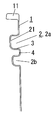
また、請求項3に係る発明にあっては、請求項1又は2に係る発明において、前記凹み部2を上側の凹み部2aとすると共に、上側の凹み部2aの下側を凹ませて下側の凹み部2bを形成し、上側の凹み部2aと下側の凹み部2bとの間の凸となった部分を掴み部4として成ることを特徴とするものである。
In the invention according to
このような構成とすることで、上側の凹み部2aの手掛け面3に手を掛けると共に、下側の凹み部2bに指先を挿入して掴み部4を掴むことができて、より一層安定した手摺りとすることができる。
By adopting such a configuration, it is possible to place the hand on the
本発明にあっては、浴槽の内面に一部を凹ませて凹み部を形成し、凹み部の下端部を略上方を向いて人体の手を載置することのできる手掛け面として手摺りを構成したことで、握力が弱い入浴者の場合でも、浴槽内において立ち上がる際、上記握り部や握りバーをしっかり握って体重を掛ける必要がなく、手掛け面に手を載置して体重を掛けることができて、容易に立ち上がることが可能となって、手摺りとしての機能が充分に果たされるものとなる。 In the present invention, a handrail is formed as a handgrip surface on which a part of the inner surface of the bathtub is recessed to form a recessed portion, and the lower end portion of the recessed portion faces substantially upward, and a human hand can be placed thereon. With this configuration, even if you are a bather with weak grip, when you stand up in the bathtub, you do not need to hold the grip part or grip bar firmly and put your weight on it. Thus, it becomes possible to stand up easily, and the function as a handrail is sufficiently fulfilled.
以下、本発明を添付図面に示す実施形態に基づいて説明する。 Hereinafter, the present invention will be described based on embodiments shown in the accompanying drawings.
浴槽1は、例えばFRP等のような合成樹脂やその他の材料にて形成されていて、床パン上に載置される。床パンは、図示はしないが、浴槽床パン及び洗い場床パンを別々に備えた床パンや、あるいは浴槽設置部と洗い場部とを備えた一体の床パンであってもよく、特に限定されない。また、洗い場床パンのみを有するいわゆるハーフ床パンであってもよく、この場合には浴室の床スラブ上に載置される。また、浴槽1と床パンが一体に形成してあってもよく、特に限定されないものである。
The
浴槽1は、浴水が内部に溜まる上方に開口する凹部を有するものであれば特に限定されないものであり、平面視における形状は、一般的には浴槽1のフランジ部11の輪郭が略矩形状をしているが特に限定されないものであり、浴水が内部に溜まる上方に開口する凹部の平面視における形状も、略楕円形状や略矩形状等、特に限定されないものである。
The
そして、浴槽1の内面(内側面)には、一部を凹ませて手摺りとしての凹み部2を形成するものである。本実施形態では、浴槽1の内面の全周に亘って、上下幅が略一定の凹み部2を水平に形成してあるが、浴槽1の内面の全周のうちの一部でもよい。
And in the inner surface (inner surface) of the
凹み部2の断面形状は、本実施形態では隅部にRを形成した略矩形状をしたもので、凹み部2の下端部の面は、上方を向く平面からなる手掛け面3となっている。
In this embodiment, the cross-sectional shape of the
この凹み部2の上下幅は、平均的な人体の手が容易に入れられる幅とするもので、例えば5cm〜20cm、好ましくは10cm〜15cm程度とする。
The vertical width of the
また、凹み部2の奥行き幅は、例えば5cm〜20cm、好ましくは10cm〜15cm程度とする。
Moreover, the depth width of the
凹み部2を形成する上下位置は、浴槽1の内面の上端部から下端部までの間のいずれの位置でもよいが、上下中央部以下の位置とすることで、手掛け面3に入浴者が手を載置して体重を掛ける際に、腕を手掛け面3に突いて立ち上がることができ、立ち上がり易くなるものである。
The upper and lower positions forming the
上記のように、浴槽1の内面に一部を凹ませて凹み部2を形成し、凹み部2の下端部を略上方を向いて人体の手を載置することのできる手掛け面3として手摺りを構成したことで、握力が弱い入浴者の場合でも、浴槽1内において立ち上がる際、上記握り部や握りバーをしっかり握って体重を掛ける必要がなく、手掛け面3に手を載置して体重を掛けることができて、容易に立ち上がることが可能となって、手摺りとしての機能が充分に果たされるものとなる。
As described above, a part of the inner surface of the
また、浴槽1の内面に凹み部2を設けたものであるため、凹み部2の奥底面21が手の滑り止めとなって、単に浴槽1の上端面に手を掛けるもののように、手が浴槽1の上端面を横に滑ってしまうといったこともないものである。
Moreover, since the
また、握りバーのように、浴槽1と握りバーとの間の隙間に手足等の身体の一部やタオルや入浴用具等が入り込んで引っ掛かったり挟まったりする、といったことも勿論ないものである。
In addition, like a grip bar, there is of course no part of the body such as limbs, towels, bathing tools, or the like that get caught or caught in the gap between the
また、凹み部2を浴槽1の内面に全周に亘って形成することで、全周のいずれの位置にでも凹み部2の手掛け面3に手を掛けることができて使い勝手が向上するものである。
Moreover, by forming the
また、図3に示すように、前記手掛け面3を有する凹み部2を上側の凹み部2aとすると共に、上側の凹み部2aの下側に、別の下側の凹み部2bを形成してもよい。下側の凹み部2bは、特に下端部に手掛け面3を形成する必要はないものである。
Further, as shown in FIG. 3, the
このように、上側の凹み部2aの下側に下側の凹み部2bを形成し、上側の凹み部2aと下側の凹み部2bとの間の凸となった部分を掴み部4とすることで、上側の凹み部2aの手掛け面3に手を掛けると共に下側の凹み部2bに指先を挿入して掴み部4を掴むことができて、より一層安定するものである。
In this way, the
1 浴槽
2 凹み部
2a 上側の凹み部
2b 下側の凹み部
21 奥底面
3 手掛け面
4 掴み部
DESCRIPTION OF
Claims (3)
Priority Applications (1)
| Application Number | Priority Date | Filing Date | Title |
|---|---|---|---|
| JP2007168192A JP2009005776A (en) | 2007-06-26 | 2007-06-26 | Bathtub with handrail |
Applications Claiming Priority (1)
| Application Number | Priority Date | Filing Date | Title |
|---|---|---|---|
| JP2007168192A JP2009005776A (en) | 2007-06-26 | 2007-06-26 | Bathtub with handrail |
Publications (1)
| Publication Number | Publication Date |
|---|---|
| JP2009005776A true JP2009005776A (en) | 2009-01-15 |
Family
ID=40321511
Family Applications (1)
| Application Number | Title | Priority Date | Filing Date |
|---|---|---|---|
| JP2007168192A Withdrawn JP2009005776A (en) | 2007-06-26 | 2007-06-26 | Bathtub with handrail |
Country Status (1)
| Country | Link |
|---|---|
| JP (1) | JP2009005776A (en) |
Cited By (1)
| Publication number | Priority date | Publication date | Assignee | Title |
|---|---|---|---|---|
| JP2012196372A (en) * | 2011-03-23 | 2012-10-18 | Panasonic Corp | Bathtub device, and water-saving member |
-
2007
- 2007-06-26 JP JP2007168192A patent/JP2009005776A/en not_active Withdrawn
Cited By (1)
| Publication number | Priority date | Publication date | Assignee | Title |
|---|---|---|---|---|
| JP2012196372A (en) * | 2011-03-23 | 2012-10-18 | Panasonic Corp | Bathtub device, and water-saving member |
Similar Documents
| Publication | Publication Date | Title |
|---|---|---|
| US7310837B2 (en) | Bathtub/shower seat | |
| US9675214B2 (en) | Oversized bath pillow | |
| JP2009005776A (en) | Bathtub with handrail | |
| JP2006334387A (en) | Bathtub | |
| JP4552605B2 (en) | Bathing railing | |
| JP2009261626A (en) | Bathroom structure | |
| JP5861979B2 (en) | Bathtub | |
| JP5144132B2 (en) | Bathroom grip bar | |
| JP2010094428A (en) | Wash basin stand and bathroom structure provided with the same | |
| JP3045192U (en) | Bathtub grabber | |
| JPH11216076A (en) | Bathtub and bathroom | |
| JP2006020988A (en) | Bath pail | |
| KR200369198Y1 (en) | Improving type shower head | |
| JP6397749B2 (en) | Bus board | |
| JP3201917U (en) | Bathtub | |
| JP6340309B2 (en) | Bus board | |
| JPS6122557Y2 (en) | ||
| KR101574477B1 (en) | Safety toilet seat installed handle for a disabled person | |
| JP2011045683A (en) | Wash pot | |
| KR200349683Y1 (en) | A bathtub | |
| JP2582165Y2 (en) | Bathtub armrests | |
| KR200273438Y1 (en) | Auxiliary sitting-plate for bath | |
| JP3012947U (en) | Bath stool | |
| JP2002303028A (en) | Handrail and bathroom | |
| JPH0710635Y2 (en) | Bath |
Legal Events
| Date | Code | Title | Description |
|---|---|---|---|
| A711 | Notification of change in applicant |
Free format text: JAPANESE INTERMEDIATE CODE: A712 Effective date: 20100408 |
|
| A521 | Written amendment |
Free format text: JAPANESE INTERMEDIATE CODE: A821 Effective date: 20100416 |
|
| RD02 | Notification of acceptance of power of attorney |
Free format text: JAPANESE INTERMEDIATE CODE: A7422 Effective date: 20100416 |
|
| A300 | Withdrawal of application because of no request for examination |
Free format text: JAPANESE INTERMEDIATE CODE: A300 Effective date: 20100907 |