JP2009004877A - Data transmission device and data transmission method - Google Patents
Data transmission device and data transmission method Download PDFInfo
- Publication number
- JP2009004877A JP2009004877A JP2007161470A JP2007161470A JP2009004877A JP 2009004877 A JP2009004877 A JP 2009004877A JP 2007161470 A JP2007161470 A JP 2007161470A JP 2007161470 A JP2007161470 A JP 2007161470A JP 2009004877 A JP2009004877 A JP 2009004877A
- Authority
- JP
- Japan
- Prior art keywords
- electronic device
- data
- specified
- video
- audio
- Prior art date
- Legal status (The legal status is an assumption and is not a legal conclusion. Google has not performed a legal analysis and makes no representation as to the accuracy of the status listed.)
- Abandoned
Links
Images


Classifications
-
- H—ELECTRICITY
- H04—ELECTRIC COMMUNICATION TECHNIQUE
- H04N—PICTORIAL COMMUNICATION, e.g. TELEVISION
- H04N21/00—Selective content distribution, e.g. interactive television or video on demand [VOD]
- H04N21/40—Client devices specifically adapted for the reception of or interaction with content, e.g. set-top-box [STB]; Operations thereof
- H04N21/47—End-user applications
- H04N21/485—End-user interface for client configuration
-
- H—ELECTRICITY
- H04—ELECTRIC COMMUNICATION TECHNIQUE
- H04N—PICTORIAL COMMUNICATION, e.g. TELEVISION
- H04N21/00—Selective content distribution, e.g. interactive television or video on demand [VOD]
- H04N21/40—Client devices specifically adapted for the reception of or interaction with content, e.g. set-top-box [STB]; Operations thereof
- H04N21/43—Processing of content or additional data, e.g. demultiplexing additional data from a digital video stream; Elementary client operations, e.g. monitoring of home network or synchronising decoder's clock; Client middleware
- H04N21/436—Interfacing a local distribution network, e.g. communicating with another STB or one or more peripheral devices inside the home
- H04N21/43615—Interfacing a Home Network, e.g. for connecting the client to a plurality of peripherals
-
- H—ELECTRICITY
- H04—ELECTRIC COMMUNICATION TECHNIQUE
- H04L—TRANSMISSION OF DIGITAL INFORMATION, e.g. TELEGRAPHIC COMMUNICATION
- H04L12/00—Data switching networks
- H04L12/28—Data switching networks characterised by path configuration, e.g. LAN [Local Area Networks] or WAN [Wide Area Networks]
- H04L12/2803—Home automation networks
- H04L12/2807—Exchanging configuration information on appliance services in a home automation network
- H04L12/2809—Exchanging configuration information on appliance services in a home automation network indicating that an appliance service is present in a home automation network
-
- H—ELECTRICITY
- H04—ELECTRIC COMMUNICATION TECHNIQUE
- H04L—TRANSMISSION OF DIGITAL INFORMATION, e.g. TELEGRAPHIC COMMUNICATION
- H04L12/00—Data switching networks
- H04L12/28—Data switching networks characterised by path configuration, e.g. LAN [Local Area Networks] or WAN [Wide Area Networks]
- H04L12/2803—Home automation networks
- H04L2012/2847—Home automation networks characterised by the type of home appliance used
- H04L2012/2849—Audio/video appliances
Abstract
Description
本発明は、ソースデバイスから出力されるコンテンツデータを電子機器に伝送するデータ伝送装置およびデータ伝送方法に関する。 The present invention relates to a data transmission apparatus and a data transmission method for transmitting content data output from a source device to an electronic device.
近年、映像データを伝送するためのインタフェースとして、HDMI(High-Definition Multimedia Interface)などのインタフェース規格が用いられている。HDMIインタフェースは、デジタルテレビジョン信号のようなコンテンツデータを、DVD(Digital Versatile Disc)プレーヤのようなソースデバイスから、TVセット、プロジェクタ、オーディオシステムのような電子機器に送信するために使用される。ソースデバイスと電子機器(シンクデバイスと称されることもある)との間は一本のケーブルを介して接続される。ソースデバイスから出力されるコンテンツデータに含まれる映像データおよびオーディオデータの双方は、一本のケーブルを介して電子機器に伝送される。 In recent years, interface standards such as HDMI (High-Definition Multimedia Interface) have been used as an interface for transmitting video data. The HDMI interface is used to transmit content data such as a digital television signal from a source device such as a DVD (Digital Versatile Disc) player to an electronic device such as a TV set, a projector, or an audio system. The source device and the electronic device (sometimes referred to as a sink device) are connected via a single cable. Both video data and audio data included in the content data output from the source device are transmitted to the electronic device via a single cable.
しかし、ケーブル接続はソースデバイスおよび電子機器それぞれの設置場所を制限するので、ソースデバイスおよび電子機器をそれぞれ任意の場所に配置することは困難となる。 However, since the cable connection restricts the installation locations of the source device and the electronic device, it is difficult to place the source device and the electronic device in arbitrary locations.
特許文献1には、DVDデバイスと、TV、オーディオ機器のような電子機器との間を無線接続する無線ネットワークシステムが開示されている。この無線ネットワークシステムにおいては、DVDデバイスと電子機器それぞれとの間の距離が検出され、DVDデバイスから所定距離内に存在する電子機器が優先的にDVDデバイスに無線接続される。
しかし、特許文献1のシステムにおいては、映像出力に使用すべき電子機器とオーディオ出力に使用すべき電子機器との組み合わせの選択に関しては特に考慮されていない。HDMIのようなインタフェースが無線化されたならば、ソースデバイスは複数の電子機器に容易に無線接続することができる。このため、ソースデバイスから出力されるコンテンツデータに含まれる映像データおよびオーディオデータそれぞれを任意の電子機器に伝送するための新たな機能の実現が必要である。
However, in the system of
本発明は上述の事情を考慮してなされたものであり、ソースデバイスからのコンテンツデータに含まれる映像データおよびオーディオデータそれぞれを複数の電子機器内の任意の1以上の電子機器に伝送することが可能なデータ伝送装置およびデータ伝送方法を提供することを目的とする。 The present invention has been made in consideration of the above-described circumstances, and each of video data and audio data included in content data from a source device can be transmitted to any one or more electronic devices in a plurality of electronic devices. An object of the present invention is to provide a possible data transmission apparatus and data transmission method.
上述の課題を解決するため、本発明は、ソースデバイスに接続され、前記ソースデバイスから出力されるコンテンツデータを複数の電子機器に無線信号によって選択的に伝送するデータ伝送装置であって、前記複数の電子機器それぞれとの無線通信によって前記複数の電子機器それぞれの機能を検出する機能検出手段と、前記検出された前記複数の電子機器それぞれの機能に応じて、前記複数の電子機器を、各々のグループが映像表示に使用可能な電子機器とオーディオ出力に使用可能な電子機器との組み合わせ、または映像表示およびオーディオ出力の双方に使用可能な一つの電子機器を含む、複数のグループに分類し、前記複数のグループそれぞれの構成の一覧を示すリスト情報を生成するリスト情報生成手段と、前記生成されたリスト情報を前記ソースデバイスに送信するリスト情報送信手段と、前記ソースデバイスから出力される前記複数のグループの一つを指定する選択情報に応じて、前記複数の電子機器の内から前記コンテンツデータに含まれる映像データを伝送すべき第1の電子機器と前記コンテンツデータに含まれるオーディオデータを伝送すべき第2の電子機器とを特定し、前記特定された第1の電子機器と前記特定された第2の電子機器とが異なる電子機器である場合、前記コンテンツデータに含まれる映像データおよびオーディオデータを前記特定された第1の電子機器および第2の電子機器にそれぞれ無線信号によって伝送し、前記特定された第1の電子機器と前記特定された第2の電子機器とが一つの電子機器である場合、前記コンテンツデータに含まれる映像データおよびオーディオデータを前記一つの電子機器に無線信号によって伝送するデータ伝送制御手段とを具備することを特徴とする。 In order to solve the above-described problems, the present invention provides a data transmission apparatus that is connected to a source device and selectively transmits content data output from the source device to a plurality of electronic devices by radio signals. Function detecting means for detecting the function of each of the plurality of electronic devices by wireless communication with each of the plurality of electronic devices, and depending on the detected function of each of the plurality of electronic devices, The group is classified into a plurality of groups including a combination of electronic devices that can be used for video display and electronic devices that can be used for audio output, or one electronic device that can be used for both video display and audio output. List information generating means for generating list information indicating a list of configurations of each of a plurality of groups, and the generated list Information included in the content data from among the plurality of electronic devices in accordance with list information transmitting means for transmitting information to the source device and selection information designating one of the plurality of groups output from the source device A first electronic device to transmit the video data to be transmitted and a second electronic device to transmit the audio data included in the content data are identified, and the identified first electronic device and the identified first electronic device are identified. When the electronic device of 2 is different from the electronic device, video data and audio data included in the content data are transmitted to the specified first electronic device and the second electronic device by radio signals, respectively, and the specified Included in the content data when the first electronic device and the identified second electronic device are one electronic device. That is characterized by comprising a data transmission control means for transmitting the radio signal to video data and audio data to the one of the electronic device.
本発明によれば、ソースデバイスからのコンテンツデータに含まれる映像データおよびオーディオデータそれぞれを複数の電子機器内の任意の1以上の電子機器に伝送することが可能となる。 According to the present invention, video data and audio data included in content data from a source device can be transmitted to any one or more electronic devices in a plurality of electronic devices.
以下、図面を参照して、本発明の実施形態を説明する。
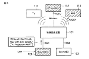
図1には、本発明の一実施形態に係るデータ伝送装置を含む無線伝送システムの構成例が示されている。この無線伝送システムは、映像伝送装置101、TVセット111、プロジェクタ112、AVアンプ(オーディオシステム)113、ソースデバイス121,122、等から構成されている。
Hereinafter, embodiments of the present invention will be described with reference to the drawings.
FIG. 1 shows a configuration example of a wireless transmission system including a data transmission apparatus according to an embodiment of the present invention. The wireless transmission system includes a
映像伝送装置101は本実施形態のデータ伝送装置であり、ソースデバイス121,122の各々から出力される、映像データおよびオーディオデータを含むコンテンツデータを、複数の電子機器(TVセット111、プロジェクタ112、AVアンプ113、等)に無線信号によって選択的に伝送する。
The
ソースデバイス121,122の各々は、例えば、DVDプレーヤ、AVレコーダ等のデバイスであり、映像データ(非圧縮の映像データ)、およびオーディオデータを含むコンテンツデータを再生して当該コンテンツデータのストリームを出力することができる。ソースデバイス121の出力端子は、例えば、HDMI規格のケーブルを介して映像伝送装置101の入力端子に接続されている。同様に、ソースデバイス122の出力端子も、例えば、HDMI規格のケーブルを介して映像伝送装置101の別の入力端子に接続されている。
Each of the
TVセット111、プロジェクタ112、AVアンプ113の各々は、映像表示機能、オーディオ出力機能、または映像表示機能とオーディオ出力機能の双方を有する電子機器である。TVセット111、プロジェクタ112、AVアンプ113の各々は、ソースデバイスから出力されるストリーム(コンテンツデータ)を受信するSinkデバイスとして機能する。
Each of the
映像伝送装置101は、ソースデバイス121、122の各々から出力されるコンテンツデータを受信し、その受信したコンテンツデータを、無線信号によってTVセット111、プロジェクタ112、AVアンプ113に選択的に伝送する。映像送信装置101と、TVセット111、プロジェクタ112、AVアンプ113の各々との間の無線インタフェースは、例えば、HDMI規格のケーブルを無線化したものと同等の能力を持つ。この無線伝送システムにおいて使用される無線通信方式は、無線LANと比較して高速な、
例えば、WirelessHD、またはUWB(Ultra Wideband)のような高速無線通信方式が好適である。この場合、映像伝送装置101は、WirelessHD、UWBのような高速無線通信方式を用いて無線通信を実行し、またTVセット111、プロジェクタ112、AVアンプ113の各々も、WirelessHD、UWBのような高速無線通信方式を用いて無線通信を実行する。WirelessHDにおいては、60GHz帯のミリ波を用いて無線通信が実行される。
The
For example, a high-speed wireless communication system such as WirelessHD or UWB (Ultra Wideband) is suitable. In this case, the
映像伝送装置101は、例えばHDMI規格で規定された通信手順に従って、TVセット111、プロジェクタ112、AVアンプ113の各々との通無線信を実行することができる。この無線通信により、映像伝送装置101は、ソースデバイス121、122の各々から出力される、非圧縮の映像データを含むコンテンツデータをTVセット111、プロジェクタ112、AVアンプ113に選択的に伝送する。
The
映像伝送装置101は、映像伝送装置101に無線接続可能な複数の電子機器(図1の例では、TVセット111、プロジェクタ112、AVアンプ113)それぞれの機能に応じて、これら複数の電子機器を複数のグループ(複数のトポロジーグループ)に分類し、これらグループそれぞれの構成の一覧を示すリスト情報(トポロジーリスト情報)を生成する。各トポロジーグループは、映像表示に使用可能な電子機器(Sinkデバイス)とオーディオ出力に使用可能な電子機器(Sinkデバイス)との組み合わせ、または映像表示およびオーディオ出力の双方に使用可能な一つの電子機器、から構成される。
The
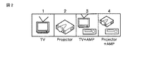
TVセット(TVデバイスとも云う)111は映像表示機能およびオーディオ出力機能の双方を有するSinkデバイスである。プロジェクタ112は、映像表示機能を有し、オーディオ出力機能は有さないSinkデバイスである。AVアンプ113はオーディオ出力機能を有し、映像表示機能を有さないSinkデバイスである。このため、これらTVセット111、プロジェクタ112、AVアンプ113それぞれの機能に応じて、映像伝送装置101は、図2に示すようなトポロジーリスト情報を生成する。
A TV set (also referred to as a TV device) 111 is a sink device having both a video display function and an audio output function. The
図2のトポロジーリスト情報においては、TVセット111、プロジェクタ112、AVアンプ113は4つのトポロジーグループに分類されている。なお、図2においては、コンテンツデータの中には、映像データのみを含み、オーディオデータを含まないものも存在することを考慮して、オーディオ出力機能のみを有するプロジェクタ2のみから構成されるトポロジーグループも、トポロジーグループの一つとして扱われている。
In the topology list information of FIG. 2, the
すなわち、トポロジーグループ1には、TVセット111のみが属している。トポロジーグループ1は、映像表示およびオーディオ出力の双方をTVセット111を用いて行うトポロジーグループである。トポロジーグループ1が例えばソースデバイス121によって選択された場合、ソースデバイス121から出力されるコンテンツデータに含まれる、映像データおよびオーディオデータの双方が、映像伝送装置101とTVセット111との間に確立された無線通信チャネルを介して、映像伝送装置101からTVセット111に伝送される。
That is, only the
トポロジーグループ2には、プロジェクタ112のみが属している。トポロジーグループ2は、映像表示をプロジェクタ112を用いて行うトポロジーグループである。トポロジーグループ2が例えばソースデバイス121によって選択された場合、ソースデバイス121から出力されるコンテンツデータに含まれる、映像データおよびオーディオデータの双方が、または当該コンテンツデータに含まれる映像データのみが、映像伝送装置101とプロジェクタ112との間に確立された無線通信チャネルを介して、映像伝送装置101からプロジェクタ112に伝送される。
Only the
トポロジーグループ3には、TVセット111とAVアンプ113とが属している。トポロジーグループ3は、映像表示をTVセット111を用いて行い、オーディオ出力をAVアンプ113を用いて行うトポロジーグループである。トポロジーグループ3が例えばソースデバイス121によって選択された場合、ソースデバイス121から出力されるコンテンツデータに含まれる映像データおよびオーディオデータの内、映像データは、映像伝送装置101とTVセット111との間に確立された無線通信チャネルを介して、映像伝送装置101からTVセット111に伝送される。一方、ソースデバイス121から出力されるコンテンツデータに含まれる映像データおよびオーディオデータの内、オーディオデータは、映像伝送装置101とAVアンプ113との間に確立された無線通信チャネルを介して、映像伝送装置101からAVアンプ113に伝送される。
In the
トポロジーグループ4には、プロジェクタ112とAVアンプ113とが属している。トポロジーグループ4は、映像表示をプロジェクタ112を用いて行い、オーディオ出力をAVアンプ113を用いて行うトポロジーグループである。トポロジーグループ4が例えばソースデバイス121によって選択された場合、ソースデバイス121から出力されるコンテンツデータに含まれる映像データおよびオーディオデータの内、映像データは、映像伝送装置101とプロジェクタ112との間に確立された無線通信チャネルを介して、映像伝送装置101からプロジェクタ112に伝送される。一方、ソースデバイス121から出力されるコンテンツデータに含まれる映像データおよびオーディオデータの内、オーディオデータは、映像伝送装置101とAVアンプ113との間に確立された無線通信チャネルを介して、映像伝送装置101からAVアンプ113に伝送される。
The
映像伝送装置101は、トポロジーリスト情報をソースデバイス121,122の各々に送信する。ソースデバイス121,122の各々は、トポロジーリスト情報によって指定される複数のトポロジーグループの中の任意の一つを指定することができる。
The
例えば、トポロジーリスト情報によって指定される複数のトポロジーグループは、ソースデバイスに設けられたチャネル切り替えボタンのような一つの操作ボタンに割り当てることができる。ユーザがこの操作ボタンを押すたびに、選択されるべきトポロジーグループは、トポロジーグループ1、2、3、4、1、…の順番で、順次切り替えられる。また、複数のトポロジーグループをソースデバイスに設けられた複数の操作ボタンにそれぞれ割り当ててもよい。
For example, a plurality of topology groups specified by the topology list information can be assigned to one operation button such as a channel switching button provided in the source device. Each time the user presses this operation button, the topology groups to be selected are sequentially switched in the order of
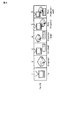
次に、図3を参照して、映像伝送装置101の構成例を説明する。
Next, a configuration example of the
映像伝送装置101は、無線通信部201、HDMIインタフェース部202、機能検出部203、トポロジーリスト生成部204、リスト情報送信部205、データ伝送制御部206、および伝送先特定部207等を備えている。
The
無線通信部201は、TVセット111、プロジェクタ112、AVアンプ113それぞれとの無線通信を実行する。HDMIインタフェース部202は、HDMIケーブルを介してソースデバイス121に接続されており、また他のHDMIケーブルを介してソースデバイス122に接続されている。HDMIインタフェース部202は、HDMIケーブルを介してソースデバイス121,122の各々との通信を実行する。
The
機能検出部203は、映像伝送装置101に無線接続可能なSinkデバイスそれぞれとの無線通信によって、それらSinkデバイスそれぞれの機能を検出する。例えば、機能検出部203は、映像伝送装置101に無線接続可能なSinkデバイスを検出するためのスキャン処理を実行し、そして検出されたSinkデバイスそれぞれの機能(能力とも云う)を検出する。例えば、映像伝送装置101からの電波が届くエリア内に、TVセット111、プロジェクタ112、AVアンプ113それぞれが存在する場合には、機能検出部203は、TVセット111、プロジェクタ112、AVアンプ113の各々との無線通信を無線通信部201を介して実行し、これによってTVセット111、プロジェクタ112、AVアンプ113の各々の機能を検出する。
The
HDMI規格においては、複数のSinkデバイスの種類それぞれに対してユニークなデバイスタイプ情報(例えばユニークな論理アドレス)が割り当てられている。したがって、機能検出部203は、スキャン処理等によって検出された複数のSinkデバイスそれぞれからデバイスタイプ情報(Sinkタイプ情報)を取得することにより、複数のSinkデバイスそれぞれの機能を検出することができる。
In the HDMI standard, unique device type information (for example, a unique logical address) is assigned to each of a plurality of types of sink devices. Therefore, the
トポロジーリスト生成部204は、機能検出部203によって検出された複数のSinkデバイスそれぞれの機能に応じて、複数のSinkデバイスを、各々のグループが映像表示に使用可能なSinkデバイスとオーディオ出力に使用可能なSinkデバイスとの組み合わせ、または映像表示およびオーディオ出力の双方に使用可能な一つのSinkデバイスを含む、複数のトポロジーグループに分類し、この複数のトポロジーグループそれぞれの構成(例えば、トポロジーグループそれぞれに属するSinkデバイス名等)の一覧を示す上述のトポロジーリスト情報を生成する。
The topology
リスト情報送信部205は、トポロジーリスト生成部204によって生成されたトポロジーリスト情報をソースデバイス121,122の各々に送信する。HDMI規格のケーブルにおいては、データ転送用のデータ伝送線群に加え、制御情報およびステータスを転送するための制御信号線であるCEC(Consumer Electronics Control)線が定義されている。このため、ソースデバイス121,122の各々へのトポロジーリスト情報の送信にはCEC線を用いることができる。データ伝送線群は、例えば、3組の差動信号線対から構成されている。
The list
ソースデバイス121,122の各々は、3組の作動信号線対を介して、コンテンツデータ(非圧縮の映像データ、オーディオデータ)を出力することができる。この場合、オーディオデータの伝送は、例えば、映像データのブランキング期間内に実行される。
Each of the
データ伝送制御部206は、ソースデバイス121または122から出力されるコンテンツデータに含まれる映像データおよびオーディオデータそれぞれの伝送先を特定し、特定された映像データ用の伝送先に対しては映像データを無線信号によって伝送し、特定されたオーディオデータ用の伝送先に対してはオーディオデータを無線信号によって伝送する。映像データおよびオーディオデータそれぞれの伝送先を特定するために、データ伝送制御部206は、伝送先特定部207を備えている。
The data
伝送先特定部207は、ソースデバイス121(または122)から出力される、複数のトポロジーグループの一つを指定する選択情報に応じて、ソースデバイス121(または122)から出力されるコンテンツデータに含まれる映像データを伝送すべき第1のSinkデバイス(ターゲットデバイス)と当該コンテンツデータに含まれるオーディオデータを伝送すべき第2のSinkデバイス(ターゲットデバイス)とを特定する。
The transmission
特定された第1のSinkデバイスと特定された第2のSinkデバイスとが異なるSinkデバイスである場合、データ伝送制御部206は、特定された第1のSinkデバイスおよび第2のSinkデバイスそれぞれとの無線通信を無線通信部201を介して実行して、ソースデバイス121(または122)から出力されるコンテンツデータに含まれる映像データおよびオーディオデータを、特定された第1のSinkデバイスおよび第2のSinkデバイス、つまり異なる2つのSinkデバイスに、それぞれ無線信号によって伝送する。ソースデバイスから出力されるコンテンツデータのストリームには映像データおよびオーディオデータが含まれているので、データ伝送制御部206は、受信したストリームから映像データおよびオーディオデータをそれぞれ抽出し、抽出した映像データを特定された第1のSinkデバイスに伝送し、抽出したオーディオデータを特定された第2のSinkデバイスに伝送する。
In the case where the identified first sink device and the identified second sink device are different sink devices, the data
一方、特定された第1のSinkデバイスと特定された第2のSinkデバイスとが一つの同一のSinkデバイスである場合、データ伝送制御部206は、当該一つのSinkデバイスとの無線通信を無線通信部201を介して実行して、ソースデバイス121(または122)から出力されるコンテンツデータに含まれる映像データおよびオーディオデータを、当該一つのSinkデバイスに無線信号によって伝送する。
On the other hand, when the specified first sink device and the specified second sink device are one and the same sink device, the data
前述の選択情報は、例えば、Sinkデバイスから出力されるメッセージに付加することができる。このメッセージは、Sinkデバイスが、コンテンツデータを伝送すべき伝送先Sinkデバイスに対して、映像表示またはオーディオ出力をすべきことを指示するメッセージである。このメッセージは、例えば、HDMI規格で定義されたワンタッチプレイ機能の実現のために使用することができる。ワンタッチプレイ機能は、ユーザがソースデバイスの操作ボタンを一回押すだけで、ソースデバイスに対してコンテンツデータのストリームの出力を実行させ、且つソースデバイスに結合された伝送先Sinkデバイスに対してストリームの処理(映像表示、オーディオ出力)を開始させる機能である。 The selection information described above can be added to a message output from the sink device, for example. This message is a message instructing that the sink device should display video or output audio to the transmission destination sink device to which the content data is to be transmitted. This message can be used, for example, for realizing a one-touch play function defined in the HDMI standard. The one-touch play function allows the source device to output a stream of content data with a single press of the operation button of the source device and the stream of the stream to the transmission destination sink device coupled to the source device. This function starts processing (video display, audio output).
本実施形態のシステムにおいては、任意のSinkデバイスを用いたワンタッチプレイ機能を実現するために、例えば、上述のワンタッチプレイ用のメッセージに選択情報が付加された状態で、当該メッセージがソースデバイスから映像伝送装置101に送信される。すなわち、ユーザがソースデバイスに設けられたある操作ボタンを押すと、ソースデバイスは、伝送先Sinkデバイスに対して映像表示またはオーディオ出力をすべきことを指示する、ワンタッチプレイ用のメッセージを出力すると共に、コンテンツデータの出力を開始する。このメッセージには、そのメッセージに対応する引数として、一つのトポロジーグループを指定する選択情報が付加されている。選択情報が付加されたメッセージは、例えば、上述のCEC線を介してソースデバイスから映像伝送装置101に伝送され、またコンテンツデータはデータ伝送線群を介してソースデバイスから映像伝送装置101に伝送される。
In the system of this embodiment, in order to realize a one-touch play function using an arbitrary sink device, for example, in a state where selection information is added to the above-mentioned one-touch play message, the message is transmitted from the source device. It is transmitted to the
伝送先特定部207は、ソースデバイスから出力されるメッセージに付加された選択情報に応じて、複数のSinkデバイスの中から、第1のSinkデバイスと第2のSinkデバイスとを特定する。
The transmission
特定された第1のSinkデバイスと特定された第2のSinkデバイスとが異なるSinkデバイスである場合、データ伝送制御部206は、特定された第1のSinkデバイスおよび第2のSinkデバイスそれぞれとの無線通信を無線通信部201を介して実行して、ソースデバイスから出力されるメッセージと、ソースデバイスから出力されるコンテンツデータに含まれる映像データとを、特定された第1のSinkデバイスに無線信号によって伝送すると共に、上記メッセージと、ソースデバイスから出力されるコンテンツデータに含まれるオーディオデータとを、特定された第2のSinkデバイスに無線信号によって伝送する。これにより、異なる2つのSinkデバイスにそれぞれワンタッチプレイ機能を実行させることが可能となる。
In the case where the identified first sink device and the identified second sink device are different sink devices, the data
一方、特定された第1のSinkデバイスと特定された第2のSinkデバイスとが一つの同一のSinkデバイスである場合、データ伝送制御部206は、当該一つのSinkデバイスとの無線通信を無線通信部201を介して実行して、ソースデバイスから出力されるメッセージと、ソースデバイスから出力されるコンテンツデータに含まれる映像データおよびオーディオデータとを、当該一つのSinkデバイスに無線信号によって伝送する。
On the other hand, when the specified first sink device and the specified second sink device are one and the same sink device, the data
次に、図4および図5を参照して、映像伝送装置101の動作例について説明する。
Next, an operation example of the
図4は、映像伝送装置101からソースデバイス121,122の各々にトポロジーリスト情報を送信する動作を示している。
FIG. 4 shows an operation of transmitting topology list information from the
映像伝送装置101は、トポロジーグループ1〜4それぞれの構成を示すトポロジーリスト情報を生成する。このトポロジーリスト情報においては、トポロジーグループ1〜4それぞれに関連づけられたSinkデバイス識別情報が含まれている。Sinkデバイス識別情報は、対応するトポロジーグループに属する1以上のSinkデバイスを示す。例えば、トポロジーグループ1に関連づけられたSinkデバイス識別情報には、TVセットを識別する識別情報(TV)が含まれている。トポロジーグループ2に関連づけられたSinkデバイス識別情報には、プロジェクタを識別する識別情報(プロジェクタ)が含まれている。トポロジーグループ3に関連づけられたSinkデバイス識別情報には、TVセットを識別する識別情報(TV)とAVアンプを識別する識別情報(AMP)とが含まれている。トポロジーグループ4に関連づけられたSinkデバイス識別情報には、プロジェクタを識別する識別情報(プロジェクタ)とAVアンプを識別する識別情報(AMP)とが含まれている。トポロジーグループ1〜4は、例えば、Sinkデバイスに設けられた4つの操作ボタンに割り当てることができる。もちろん、トポロジーグループ1〜4を、Sinkデバイスに設けられた1つの操作ボタンに割り当ててもよい。
The
図5には、ソースデバイス121から出力される選択情報付きメッセージを受信に応答して実行される映像伝送装置101の動作を示している。
FIG. 5 shows an operation of the
ここでは、トポロジーグループ1〜4がSinkデバイスに設けられた4つの操作ボタンにそれぞれ割り当てられている場合を想定する。4つの操作ボタンの内の1つがユーザによって操作された時、ソースデバイス121は、操作された操作ボタンに割り当てられたトポロジーグループを指定する選択情報付きのメッセージをCEC線を介して映像伝送装置101に送信すると共に、コンテンツデータをプレイバックする処理を開始し、コンテンツデータのストリームをデータ伝送線群を介して映像伝送装置101に送信する。このストリームには、映像データとオーディオデータとが含まれている。
Here, it is assumed that the
図5においては、トポロジーグループ4を指定する選択情報付きのメッセージ(<One Touch Play with Sink Select>)が出力された場合を示している。メッセージ<One Touch Play with Sink Select>に付加された選択情報は、例えば、トポロジーグループ4を指定するグループ番号(=4)と、トポロジーグループ4に属するSinkデバイス識別情報(プロジェクタおよびAMP)とが含まれている。
FIG. 5 shows a case where a message with selection information (<One Touch Play with Sink Select>) specifying
トポロジーグループ4を指定する選択情報付きのメッセージを受信すると、映像伝送装置101は、その選択情報に応じて、プロジェクタ112を映像データを伝送すべき第1のSinkデバイスとして特定すると共に、AVアンプ113をオーディオデータを伝送すべき第2のSinkデバイスとして特定する。そして、映像伝送装置101は、受信したメッセージ<One Touch Play with Sink Select>から選択情報を取り除き、メッセージ<One Touch Play>のみをプロジェクタ112に無線信号によって伝送すると共に、ソースデバイス121から受信したコンテンツデータに含まれる映像データをプロジェクタ112に無線信号によって伝送する。さらに、映像伝送装置101は、メッセージ<One Touch Play>をAVアンプ113に無線信号によって伝送すると共に、ソースデバイス121から受信したコンテンツデータに含まれるオーディオデータをAVアンプ113に無線信号によって伝送する。
When receiving the message with selection information specifying the
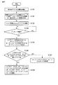
次に、図6のフローチャートを参照して、映像伝送装置101によって実行される一連の処理手順を説明する。
Next, a series of processing procedures executed by the
まず、映像伝送装置101は、映像伝送装置101に無線接続可能なSinkデバイスそれぞれとの無線通信によって、それらSinkデバイスそれぞれの機能を検出する(ステップS101)。このステップS101では、映像伝送装置101は、例えば、特定種類のSinkデバイスを探索するための問い合わせパケットをブロードキャストして当該特定種類のSinkデバイスからの応答の有無を判別する処理を、探索対象とすべきSinkデバイスの種類を変更しながら繰り返し実行する。これにより、映像伝送装置101に無線接続可能なSinkデバイスそれぞれの機能を検出することができる。
First, the
次いで、映像伝送装置101は、検出されたSinkデバイスそれぞれの機能に応じて、それらSinkデバイスを、それらSinkデバイスによって構成し得る複数のトポロジーグループに分類し、これら複数のトポロジーグループそれぞれの構成の一覧を示すトポロジーリスト情報を生成する(ステップS102)。映像伝送装置101は、生成したトポロジーリスト情報を各ソースデバイスに送信する(ステップS103)。
Next, the
あるソースデバイスから送信される、選択情報付きメッセージを受信すると(ステップS104のYES)、映像伝送装置101は、選択情報付きメッセージに含まれる選択情報に応じて、ソースデバイスからの映像データが伝送されるべき第1のSinkデバイス(ビデオデータ用ターゲットデバイス)と、ソースデバイスからのオーディオデータが伝送されるべき第2のSinkデバイス(オーディオデータ用ターゲットデバイス)とを特定する(ステップS105)。このステップS105では、映像伝送装置101は、生成したトポロジーリスト情報を参照して、選択情報によって指定されたトポロジーグループに属するSinkデバイスを検出する。選択情報内に、当該選択情報によって指定されたトポロジーグループに属する各SinkデバイスのSinkデバイス識別情報が含まれているならば、映像伝送装置101は、生成したトポロジーリスト情報を参照せずとも、ビデオデータ用ターゲットデバイスとオーディオデータ用ターゲットデバイスとを特定することができる。
When a message with selection information transmitted from a certain source device is received (YES in step S104), the
次いで、映像伝送装置101は、ビデオデータ用ターゲットデバイスとオーディオデータ用ターゲットデバイスとが同じ一つのSinkデバイスであるか否かを判定する(ステップS106)。
Next, the
ビデオデータ用ターゲットデバイスとオーディオデータ用ターゲットデバイスとが同じ一つのSinkデバイスであるならば(ステップS106のYES)、映像伝送装置101は、当該1つのSinkデバイスとの無線接続を確立し、そして、当該1つのSinkデバイスに対して、ソースデバイスから受信したメッセージと、ソースデバイスから受信したコンテンツデータ(ビデオデータおよびオーディオデータ)とを伝送する(ステップS107)。
If the target device for video data and the target device for audio data are the same sink device (YES in step S106), the
ビデオデータ用ターゲットデバイスとオーディオデータ用ターゲットデバイスとが異なる2つのSinkデバイスであるならば(ステップS106のNO)、映像伝送装置101は、ビデオデータ用ターゲットデバイスとして特定されたSinkデバイスとオーディオデータ用ターゲットデバイスとして特定されたSinkデバイスそれぞれとの無線接続を確立し、そして、ビデオデータ用ターゲットデバイスとして特定されたSinkデバイスに対して、ソースデバイスから受信したメッセージと、ソースデバイスから受信したコンテンツデータに含まれるビデオデータとを伝送し、オーディオデータ用ターゲットデバイスとして特定されたSinkデバイスに対して、ソースデバイスから受信したメッセージと、ソースデバイスから受信したコンテンツデータに含まれるオーディオデータとを伝送する(ステップS108)。
If the video data target device and the audio data target device are two different sink devices (NO in step S106), the
以上のように、本実施形態においては、ソースデバイスからのコンテンツデータに含まれる映像データおよびオーディオデータそれぞれを複数のSinkデバイス内の任意の1以上のSinkデバイスに伝送することが可能となる。特に、選択情報が付加されたメッセージを用いることにより、複数のSinkデバイスに選択的に無線接続可能な環境においても、任意のSinkデバイスを対象に、そのSinkデバイスに映像表示またはオーディオ出力を自動的に実行させるというワンタッチプレイ機能を実現することができる。 As described above, in the present embodiment, each of video data and audio data included in content data from a source device can be transmitted to any one or more sink devices in the plurality of sink devices. In particular, by using a message to which selection information is added, video display or audio output is automatically performed on any sink device even in an environment where it can be selectively wirelessly connected to a plurality of sink devices. It is possible to realize a one-touch play function to be executed.
なお、メッセージとは無関係に、選択情報のみをSinkデバイスから映像伝送装置101に送信するようにしてもよい。
Note that only the selection information may be transmitted from the sink device to the
次に、図7を参照して、本実施形態の映像伝送装置101を含む無線伝送システムの他の構成例を説明する。
Next, another configuration example of the wireless transmission system including the
図7の無線伝送システムにおいては、映像伝送装置101は、例えば、パーソナルコンピュータのような情報処理装置から構成されている。この映像伝送装置101は、ユーザの操作に応じて、トポロジーリスト情報によって示される複数のトポロジーグループの内から、使用すべき一つのトポロジーグループを選択する機能を有している。すなわち、映像伝送装置101は、生成したトポロジーリスト情報を、映像伝送装置101に設けられた画面、またはTVセット111のようなSinkデバイスの画面上に表示し、ユーザによる映像伝送装置101に設けられた入力装置(操作ボタン、キーボード、リモコンユニット、マウス、等)の操作に応じて、使用すべき一つのトポロジーグループを複数のトポロジーグループの中から選択する。この映像伝送装置101の機能により、ユーザは、映像表示、オーディオ出力を実行させるべき伝送先Sinkデバイス(または伝送先のSinkデバイス群)を容易に切り替えることが出来る。
In the wireless transmission system of FIG. 7, the
伝送先Sinkデバイスの切り替え動作は、例えば、以下の手順で実行される。 The switching operation of the transmission destination sink device is executed by the following procedure, for example.
(1)ユーザからの要求に応答して、映像伝送装置101は、生成したトポロジーリスト情報(トポロジーグループ1,2,3,4)を、例えば、TVセット111のようなSinkデバイスの画面上に表示する。ユーザは、映像伝送装置101に設けられた入力装置を操作することにより、トポロジーグループ1,2,3,4の内の一つを指定する。映像伝送装置101は、ユーザによって指定されたトポロジーグループを選択し、選択されたトポロジーグループに応じて、複数のSinkデバイスの内から、映像データを伝送すべき第1のSinkデバイス(ビデオデータ用ターゲットデバイス)とオーディオデータを伝送すべき第2のSinkデバイス(オーディオデータ用ターゲットデバイス)とを特定する。そして、映像伝送装置101は、ソースデバイスからの映像データをビデオデータ用ターゲットデバイスに無線信号によって伝送すると共に、ソースデバイスからのオーディオデータをオーディオデータ用ターゲットデバイスに無線信号によって伝送する。
(1) In response to a request from the user, the
例えば、今、TVセット111に映像データおよびオーディオデータが伝送されている状態で、ユーザによって、トポロジーグループ4が新たに指定された場合を想定する。映像伝送装置101は、トポロジーグループ4に属するプロジェクタ112およびAVアンプ113それぞれとの無線接続を確立し、そして、ソースデバイスからの映像データをプロジェクタ112に無線信号によって伝送する処理と、ソースデバイスからのオーディオデータをAVアンプ113に伝送する処理を開始する。
For example, it is assumed that the
この場合、TVセット111が表示可能な映像データフォーマット(例えば、映像データ解像度、ピクセルエンコード方式(RGB4:4:4,YCrCb4:4:4,YCrCb4:2:2,YCrCb4:2:0,等))とプロジェクタ112が表示可能な映像データフォーマットとが異なる場合がある。同様に、TVセット111が処理可能なオーディオデータフォーマット(例えば、オーディオデータの信号のフォーマット、等)とAVアンプ113が処理可能なオーディオデータフォーマットとが異なる場合もある。
In this case, the video data format that the
そこで、映像伝送装置101は、新たに選択されたビデオデータ用ターゲットデバイスが表示可能な映像データフォーマットを示すビデオデータ用ターゲットデバイスの機器情報、例えば、プロジェクタ112の機器情報を、ソースデバイスに通知する。また、映像伝送装置101は、新たに選択されたオーディオデータ用ターゲットデバイスが処理可能なオーディオデータフォーマットを示すオーディオデータ用ターゲットデバイスの機器情報、例えば、AVアンプ113の機器情報を、ソースデバイスに通知する
HDMI規格に対応する各Sinkデバイスは、EDID(Extended Display Identification Data)と称される情報を保持している。この情報は、対応するSinkデバイスがサポートする映像データフォーマット、オーディオデータフォーマット等を示す機器情報を含んでいる。したがって、映像伝送装置101は、例えば、プロジェクタ112のEDIDおよびAVアンプ113のEDIDを用いることにより、プロジェクタ112が表示可能な映像データフォーマットおよびAVアンプ113が処理可能なオーディオデータフォーマットをソースデバイスに通知することができる。
Therefore, the
この通知の処理は、例えば、以下の手順で行うことが出来る。 This notification process can be performed, for example, by the following procedure.
(2)例えば、トポロジーグループ1からトポロジーグループ4への切り替え時においては、映像伝送装置101は、ソースデバイスに通知すべきSinkデバイスのEDIDを、TVセット111が表示可能なビデオデータフォーマットおよびTVセット111が処理可能なオーディオデータフォーマットを示す情報から、プロジェクタ112が表示可能なビデオデータフォーマットおよびAVアンプ113が処理可能なオーディオデータフォーマットを示す情報に更新する。
(2) For example, when switching from
(3)次いで、映像伝送装置101は、HDMIケーブル内に定義されたホットプラグ検出信号をリセットする。すなわち、映像伝送装置101は、ホットプラグ検出信号を一旦ディスエーブル状態に設定した後、ホットプラグ検出信号をイネーブル状態に設定する。このホットプラグ検出信号は、Sinkデバイスがレディ状態になったことをソースデバイスに通知するための信号である。ホットプラグ検出信号がイネーブルになった時、ソースデバイスは、SinkデバイスのEDIDを取得する処理を自動的に開始する。これにより、変更された新たなEDID(プロジェクタ112が表示可能なビデオデータフォーマットを示す情報、AVアンプ113が処理可能なオーディオデータフォーマットを示す情報)をソースデバイスに通知することができる。
(3) Next, the
(4)この後、映像伝送装置101は、ソースデバイスに対して新たな論理アドレスを割り当てる処理を必要に応じて実行する。
(4) Thereafter, the
ソースデバイスは、映像データを新たなSinkデバイスが表示可能なビデオデータフォーマットにエンコードし、そのエンコードした映像データを出力する。また、ソースデバイスは、オーディオデータを新たなSinkデバイスが処理可能なオーディオデータフォーマットにエンコードし、そのエンコードしたオーディオデータを出力する。 The source device encodes the video data into a video data format that can be displayed by the new sink device, and outputs the encoded video data. The source device encodes the audio data into an audio data format that can be processed by the new sink device, and outputs the encoded audio data.
なお、映像伝送装置101がパーソナルコンピュータから構成されている場合においては、ソースデバイスは、例えば、映像伝送装置101に内蔵されたDVDドライブおよびこのDVDドライブを制御するソフトウェアによって実現することもできる。
In the case where the
図8には、トポロジーグループの他の例が示されている。 FIG. 8 shows another example of the topology group.
図8のトポロジーリスト情報においては、前述のトポロジーグループ1〜4に加え、トポロジーグループ5,6が設けられている。
In the topology list information of FIG. 8,
トポロジーグループ5には、TVセット111とプロジェクタ112とが属している。このトポロジーグループ5は、例えば、2つの異なる画面イメージを同時に2つのSinkデバイス(TVセット111とプロジェクタ112)に表示するため等に用いられる。
A
トポロジーグループ6には、TVセット111とプロジェクタ112とAVアンプ113とが属している。このトポロジーグループ6は、例えば、2つの異なる画面イメージを同時に2つのSinkデバイス(TVセット111とプロジェクタ112)に表示し、オーディオデータの出力処理をAVアンプ113に実行させる場合等に利用される。
The
使用すべきトポロジーグループの切替は、例えば、キーボード上のキーの操作によって行うこともできる。例えば、ユーザが“Fn”キーと“F5”キーとを同時に押すたびに、使用すべきトポロジーグループを、トポロジーグループ1、2、3、4、5、6、1、2、…のように切り替えることができる。
The topology group to be used can be switched, for example, by operating a key on the keyboard. For example, every time the user presses the “Fn” key and the “F5” key at the same time, the topology group to be used is switched to
次に、図9を参照して、図7のシステム構成に適用される映像伝送装置101の構成例を説明する。
Next, a configuration example of the
この映像伝送装置101は、図3で説明したリスト情報送信部205の代わりに、リスト情報表示部301およびグループ選択部302を備えている。さらに、映像伝送装置101は、機器情報通知部303も備えている。他の点は、図3の構成と同じである。
The
リスト情報表示部301は、ユーザからの要求に応じて、トポロジーリスト生成部204によって生成されたトポロジーリスト情報を映像伝送装置101に設けられた画面またはSinkデバイスの画面上に表示する。グループ選択部302は、ユーザ操作に応じて、トポロジーリスト情報によって示される複数のトポロジーグループの一つを選択する。
The list
伝送先特定部207は、グループ選択部302によって選択されたトポロジーグループに応じて、ソースデバイスから出力されるコンテンツデータに含まれる映像データを伝送すべき第1のSinkデバイス(ビデオデータ用ターゲットデバイス)と当該コンテンツデータに含まれるオーディオデータを伝送すべき第2のSinkデバイス(オーディオデータ用ターゲットデバイス)とを特定する。
The transmission
機器情報通知部303は、特定されたビデオデータ用ターゲットデバイスが表示可能な映像データフォーマットを示すビデオデータ用ターゲットデバイスの機器情報と、特定されたオーディオデータ用ターゲットデバイスが処理可能なオーディオデータフォーマットを示すオーディオデータ用ターゲットデバイスの機器情報とを、ソースデバイスに通知する処理を実行する。
The device
次に、図10のフローチャートを参照して、図10に示した映像伝送装置101によって実行される一連の処理手順を説明する。
Next, a series of processing procedures executed by the
まず、映像伝送装置101は、映像伝送装置101に無線接続可能なSinkデバイスそれぞれとの無線通信によって、それらSinkデバイスそれぞれの機能を検出する(ステップS201)。このステップS201では、映像伝送装置101は、例えば、特定種類のSinkデバイスを探索するための問い合わせパケットをブロードキャストして当該特定種類のSinkデバイスからの応答の有無を判別する処理を、探索対象とすべきSinkデバイスの種類を変更しながら繰り返し実行する。これにより、映像伝送装置101に無線接続可能なSinkデバイスそれぞれの機能を検出することができる。
First, the
次いで、映像伝送装置101は、検出されたSinkデバイスそれぞれの機能に応じて、それらSinkデバイスを、それらSinkデバイスが取り得る複数のトポロジーグループに分類し、これら複数のトポロジーグループそれぞれの構成の一覧を示すトポロジーリスト情報を生成する(ステップS202)。映像伝送装置101は、生成したトポロジーリスト情報を、映像伝送装置101に設けられた画面またはSinkデバイスの画面上に表示する(ステップS203)。この後、映像伝送装置101は、ユーザ操作に応じて、トポロジーグループの1つを選択する(ステップS204)。
Next, the
そして、映像伝送装置101は、選択されたトポロジーグループに応じて、ソースデバイスからの映像データが伝送されるべき第1のSinkデバイス(ビデオデータ用ターゲットデバイス)と、ソースデバイスからのオーディオデータが伝送されるべき第2のSinkデバイス(オーディオデータ用ターゲットデバイス)とを特定する(ステップS205)。
Then, the
次いで、映像伝送装置101は、ビデオデータ用ターゲットデバイスとオーディオデータ用ターゲットデバイスとが同じ一つのSinkデバイスであるか否かを判定する(ステップS206)。
Next, the
ビデオデータ用ターゲットデバイスとオーディオデータ用ターゲットデバイスとが同じ一つのSinkデバイスであるならば(ステップS206のYES)、映像伝送装置101は、当該1つのSinkデバイスの機器情報(当該1つのSinkデバイスが表示可能な映像データフォーマットと、当該1つのSinkデバイスが処理可能なオーディオデータフォーマットとを示す)をソースデバイスに通知する(ステップS207)。そして、映像伝送装置101は、当該1つのSinkデバイスとの無線接続を確立し、そして、当該1つのSinkデバイスに対して、ソースデバイスから受信したコンテンツデータ(ビデオデータおよびオーディオデータ)を伝送する(ステップS208)。
If the target device for video data and the target device for audio data are the same one sink device (YES in step S206), the
ビデオデータ用ターゲットデバイスとオーディオデータ用ターゲットデバイスとが異なる2つのSinkデバイスであるならば(ステップS206のNO)、映像伝送装置101は、ビデオデータ用ターゲットデバイスの機器情報(ビデオデータ用ターゲットデバイスが表示可能な映像データフォーマットを示す)とオーディオデータ用ターゲットデバイスの機器情報(オーディオデータ用ターゲットデバイスが処理可能なオーディオデータフォーマットを示す)とをソースデバイスに通知する(ステップS209)。
If the target device for video data and the target device for audio data are two different sink devices (NO in step S206), the
次いで、映像伝送装置101は、ビデオデータ用ターゲットデバイスとして特定されたSinkデバイスとオーディオデータ用ターゲットデバイスとして特定されたSinkデバイスそれぞれとの無線接続を確立し、そして、ビデオデータ用ターゲットデバイスとして特定されたSinkデバイスに対して、ソースデバイスから受信したコンテンツデータに含まれるビデオデータを伝送し、オーディオデータ用ターゲットデバイスとして特定されたSinkデバイスに対して、ソースデバイスから受信したコンテンツデータに含まれるオーディオデータを伝送する(ステップS210)。
Next, the
以上のように、図9の映像伝送装置101の構成においても、ソースデバイスからのコンテンツデータに含まれる映像データおよびオーディオデータそれぞれを複数のSinkデバイス内の任意の1以上のSinkデバイスに伝送することが可能となる。また、ユーザによる映像伝送装置101の操作に応じて、容易に、伝送先Sinkデバイスの組み合わせを変更することができる。
As described above, also in the configuration of the
なお、図3、図9で説明した機能検出部203、トポロジーリスト生成部204、リスト情報送信部205、データ伝送制御部206、伝送先特定部207、リスト情報表示部301、グループ選択部302、機器情報通知部303それぞれの機能は、映像伝送装置101内に設けられたCPUによって実行される通信制御プログラムによって実現することができる。この場合、図6のフローチャートで説明した処理、および図10のフローチャートで説明した処理は、それぞれCPUによって実行することが出来る。もちろん、上述の機能検出部203、トポロジーリスト生成部204、リスト情報送信部205、データ伝送制御部206、伝送先特定部207、リスト情報表示部301、グループ選択部302、機器情報通知部303の機能をそれぞれ専用の回路によって実現したり、またこれら機能をマイクロコンピュータやDSP等によって実現してもよい。
3 and 9, the
また、本発明は、上記実施形態そのままに限定されるものではなく、実施段階ではその要旨を逸脱しない範囲で構成要素を変形して具体化できる。また、上記実施形態に開示されている複数の構成要素の適宜な組み合わせにより種々の発明を形成できる。例えば、実施形態に示される全構成要素から幾つかの構成要素を削除してもよい。更に、異なる実施形態に構成要素を適宜組み合わせてもよい。 Further, the present invention is not limited to the above-described embodiments as they are, and can be embodied by modifying the constituent elements without departing from the scope of the invention in the implementation stage. In addition, various inventions can be formed by appropriately combining a plurality of components disclosed in the embodiment. For example, some components may be deleted from all the components shown in the embodiment. Furthermore, you may combine a component suitably in different embodiment.
101…映像伝送装置、111…TVセット、112…プロジェクタ、113…AVアンプ、121,122…ソースデバイス、201…無線通信部、202…HDMIインタフェース部、203…機能検出部、204…トポロジーリスト生成部、205…リスト情報送信部、206…データ伝送制御部、207…伝送先特定部。
DESCRIPTION OF
Claims (10)
前記複数の電子機器それぞれとの無線通信によって前記複数の電子機器それぞれの機能を検出する機能検出手段と、
前記検出された前記複数の電子機器それぞれの機能に応じて、前記複数の電子機器を、各々のグループが映像表示に使用可能な電子機器とオーディオ出力に使用可能な電子機器との組み合わせ、または映像表示およびオーディオ出力の双方に使用可能な一つの電子機器を含む、複数のグループに分類し、前記複数のグループそれぞれの構成の一覧を示すリスト情報を生成するリスト情報生成手段と、
前記生成されたリスト情報を前記ソースデバイスに送信するリスト情報送信手段と、
前記ソースデバイスから出力される前記複数のグループの一つを指定する選択情報に応じて、前記複数の電子機器の内から前記コンテンツデータに含まれる映像データを伝送すべき第1の電子機器と前記コンテンツデータに含まれるオーディオデータを伝送すべき第2の電子機器とを特定し、前記特定された第1の電子機器と前記特定された第2の電子機器とが異なる電子機器である場合、前記コンテンツデータに含まれる映像データおよびオーディオデータを前記特定された第1の電子機器および第2の電子機器にそれぞれ無線信号によって伝送し、前記特定された第1の電子機器と前記特定された第2の電子機器とが一つの電子機器である場合、前記コンテンツデータに含まれる映像データおよびオーディオデータを前記一つの電子機器に無線信号によって伝送するデータ伝送制御手段とを具備することを特徴とするデータ伝送装置。 A data transmission apparatus connected to a source device and selectively transmitting content data output from the source device to a plurality of electronic devices by radio signals,
Function detecting means for detecting the function of each of the plurality of electronic devices by wireless communication with each of the plurality of electronic devices;
Depending on the detected functions of the plurality of electronic devices, the plurality of electronic devices may be combined with an electronic device that can be used for video display by each group and an electronic device that can be used for audio output. A list information generating means for classifying into a plurality of groups including one electronic device that can be used for both display and audio output, and generating list information indicating a list of configurations of each of the plurality of groups;
List information transmitting means for transmitting the generated list information to the source device;
A first electronic device to transmit video data included in the content data from the plurality of electronic devices in response to selection information specifying one of the plurality of groups output from the source device; When the second electronic device to which the audio data included in the content data is to be transmitted is specified, and the specified first electronic device and the specified second electronic device are different electronic devices, Video data and audio data included in the content data are transmitted to the specified first electronic device and the second electronic device by radio signals, respectively, and the specified first electronic device and the specified second electronic device are transmitted. If the electronic device is a single electronic device, the video data and audio data included in the content data are transferred to the single electronic device. Data transmission apparatus characterized by comprising a data transmission control means for transmitting the radio signal.
前記データ伝送制御手段は、前記ソースデバイスから出力される前記メッセージに付加された前記選択情報に応じて前記第1の機器と前記第2の機器とを特定することを特徴とする請求項1記載のデータ伝送装置。 In response to an operation of a predetermined button provided on the source device, the source device is a message instructing the transmission destination electronic device to perform video display or audio output, and the selection information is added. Output the received message, and start outputting the content data,
The data transmission control means identifies the first device and the second device according to the selection information added to the message output from the source device. Data transmission equipment.
前記複数の電子機器それぞれとの無線通信によって前記複数の電子機器それぞれの機能を検出する機能検出手段と、
前記検出された前記複数の電子機器それぞれの機能に応じて、前記複数の電子機器を、各々のグループが映像表示に使用可能な電子機器とオーディオ出力に使用可能な電子機器との組み合わせ、または映像表示およびオーディオ出力の双方に使用可能な一つの電子機器を含む、複数のグループに分類し、前記複数のグループそれぞれの構成の一覧を示すリスト情報を生成するリスト情報生成手段と、
前記生成されたリスト情報を画面上に表示するリスト情報表示手段と、
ユーザ操作に応じて、前記リスト情報によって示される前記複数のグループの一つを選択する選択手段と、
前記選択されたグループに応じて、前記複数の電子機器の内から前記コンテンツデータに含まれる映像データを伝送すべき第1の電子機器と前記コンテンツデータに含まれるオーディオデータを伝送すべき第2の電子機器とを特定し、前記特定された第1の電子機器と前記特定された第2の電子機器とが異なる電子機器である場合、前記コンテンツデータに含まれる映像データおよびオーディオデータを前記特定された第1の電子機器および第2の電子機器にそれぞれ無線信号によって伝送し、前記特定された第1の電子機器と前記特定された第2の電子機器とが一つの電子機器である場合、前記コンテンツデータに含まれる映像データおよびオーディオデータを前記一つの電子機器に無線信号によって伝送するデータ伝送制御手段とを具備することを特徴とするデータ伝送装置。 A data transmission apparatus that selectively transmits content data output from a source device to a plurality of electronic devices by radio signals,
Function detecting means for detecting the function of each of the plurality of electronic devices by wireless communication with each of the plurality of electronic devices;
Depending on the detected functions of the plurality of electronic devices, the plurality of electronic devices may be combined with an electronic device that can be used for video display by each group and an electronic device that can be used for audio output. A list information generating means for classifying into a plurality of groups including one electronic device that can be used for both display and audio output, and generating list information indicating a list of configurations of each of the plurality of groups;
List information display means for displaying the generated list information on a screen;
Selection means for selecting one of the plurality of groups indicated by the list information in response to a user operation;
In accordance with the selected group, a first electronic device that transmits video data included in the content data and a second audio data that includes audio data included in the content data from among the plurality of electronic devices. When the electronic device is specified, and the specified first electronic device and the specified second electronic device are different electronic devices, the video data and audio data included in the content data are specified. When the first electronic device and the second electronic device specified are transmitted to the first electronic device and the second electronic device by radio signals, respectively, and the specified second electronic device is a single electronic device, Data transmission control means for transmitting video data and audio data included in content data to the one electronic device by radio signals Data transmission device according to claim Rukoto.
前記複数の電子機器それぞれとの無線通信によって前記複数の電子機器それぞれの機能を検出するステップと、
前記検出された前記複数の電子機器それぞれの機能に応じて、前記複数の電子機器を、各々のグループが映像表示に使用可能な電子機器とオーディオ出力に使用可能な電子機器との組み合わせ、または映像表示およびオーディオ出力の双方に使用可能な一つの電子機器を含む、複数のグループに分類し、前記複数のグループそれぞれの構成の一覧を示すリスト情報を生成するステップと、
前記生成されたリスト情報を前記ソースデバイスに送信するステップと、
前記ソースデバイスから出力される前記複数のグループの一つを指定する選択情報に応じて、前記複数の電子機器の内から前記コンテンツデータに含まれる映像データを伝送すべき第1の電子機器と前記コンテンツデータに含まれるオーディオデータを伝送すべき第2の電子機器とを特定する機器特定ステップと、
前記特定された第1の電子機器と前記特定された第2の電子機器とが異なる電子機器である場合、前記コンテンツデータに含まれる映像データおよびオーディオデータを前記特定された第1の電子機器および第2の電子機器にそれぞれ無線信号によって伝送し、前記特定された第1の電子機器と前記特定された第2の電子機器とが一つの電子機器である場合、前記コンテンツデータに含まれる映像データおよびオーディオデータを前記一つの電子機器に無線信号によって伝送するデータ伝送制御ステップとを具備することを特徴とするデータ伝送方法。 A data transmission method for controlling a data transmission apparatus connected to a source device and selectively transmitting content data output from the source device to a plurality of electronic devices by radio signals,
Detecting the function of each of the plurality of electronic devices by wireless communication with each of the plurality of electronic devices;
Depending on the detected functions of the plurality of electronic devices, the plurality of electronic devices may be combined with an electronic device that can be used for video display by each group and an electronic device that can be used for audio output. Classifying into a plurality of groups including one electronic device that can be used for both display and audio output, and generating list information indicating a list of configurations of each of the plurality of groups;
Sending the generated list information to the source device;
A first electronic device to transmit video data included in the content data from the plurality of electronic devices in response to selection information specifying one of the plurality of groups output from the source device; A device specifying step for specifying a second electronic device to transmit audio data included in the content data;
When the specified first electronic device and the specified second electronic device are different electronic devices, the specified first electronic device and video data and audio data included in the content data are Video data included in the content data when each of the identified first electronic device and the identified second electronic device is a single electronic device that is transmitted to each second electronic device by a radio signal. And a data transmission control step of transmitting audio data to the one electronic device by radio signals.
前記機器特定ステップは、前記ソースデバイスから出力される前記メッセージに付加された前記選択情報に応じて前記第1の機器と前記第2の機器とを特定することを特徴とする請求項7記載のデータ伝送方法。 In response to an operation of a predetermined button provided on the source device, the source device is a message instructing the transmission destination electronic device to perform video display or audio output, and the selection information is added. Output the received message, and start outputting the content data,
8. The device specifying step of specifying the first device and the second device according to the selection information added to the message output from the source device. Data transmission method.
Priority Applications (2)
| Application Number | Priority Date | Filing Date | Title |
|---|---|---|---|
| JP2007161470A JP2009004877A (en) | 2007-06-19 | 2007-06-19 | Data transmission device and data transmission method |
| US12/131,791 US20080320539A1 (en) | 2007-06-19 | 2008-06-02 | Data Transmission Apparatus and Data Transmission Method |
Applications Claiming Priority (1)
| Application Number | Priority Date | Filing Date | Title |
|---|---|---|---|
| JP2007161470A JP2009004877A (en) | 2007-06-19 | 2007-06-19 | Data transmission device and data transmission method |
Related Child Applications (1)
| Application Number | Title | Priority Date | Filing Date |
|---|---|---|---|
| JP2012055863A Division JP2012157033A (en) | 2012-03-13 | 2012-03-13 | Data transmission device and data transmission method |
Publications (1)
| Publication Number | Publication Date |
|---|---|
| JP2009004877A true JP2009004877A (en) | 2009-01-08 |
Family
ID=40137893
Family Applications (1)
| Application Number | Title | Priority Date | Filing Date |
|---|---|---|---|
| JP2007161470A Abandoned JP2009004877A (en) | 2007-06-19 | 2007-06-19 | Data transmission device and data transmission method |
Country Status (2)
| Country | Link |
|---|---|
| US (1) | US20080320539A1 (en) |
| JP (1) | JP2009004877A (en) |
Cited By (21)
| Publication number | Priority date | Publication date | Assignee | Title |
|---|---|---|---|---|
| JP2010166609A (en) * | 2010-03-25 | 2010-07-29 | Sharp Corp | Source device and radio transmission system |
| WO2010087189A1 (en) * | 2009-01-29 | 2010-08-05 | パナソニック株式会社 | Wireless audio/video transmission system, wireless transmission device, and audio output device and video output device |
| WO2010106705A1 (en) * | 2009-03-16 | 2010-09-23 | シャープ株式会社 | Radio transmission system, relay device, radio synchronization device, and radio source device |
| JP2010259119A (en) * | 2010-08-19 | 2010-11-11 | Sharp Corp | Radio transmission system |
| JP2010259118A (en) * | 2010-08-19 | 2010-11-11 | Sharp Corp | Radio transmission system |
| WO2010131316A1 (en) * | 2009-05-14 | 2010-11-18 | パナソニック株式会社 | Method of transmitting video data |
| WO2010131314A1 (en) * | 2009-05-14 | 2010-11-18 | パナソニック株式会社 | Method for transmitting video data |
| JP2010272975A (en) * | 2009-05-19 | 2010-12-02 | Toshiba Corp | Wireless transfer apparatus and wireless transfer method |
| JP2010277253A (en) * | 2009-05-27 | 2010-12-09 | Toshiba Corp | Information processor and method for changing voice output destination |
| JP2010279072A (en) * | 2010-08-19 | 2010-12-09 | Sharp Corp | Radio transmission system |
| WO2010140199A1 (en) * | 2009-06-01 | 2010-12-09 | パナソニック株式会社 | Method of transmitting video data |
| JP2011015245A (en) * | 2009-07-03 | 2011-01-20 | Hitachi Consumer Electronics Co Ltd | Video transmitter apparatus and video receiver apparatus |
| JP2011019261A (en) * | 2010-08-19 | 2011-01-27 | Sharp Corp | Wireless transmission system |
| JP2011019262A (en) * | 2010-08-19 | 2011-01-27 | Sharp Corp | Radio transmission system |
| JP2011082633A (en) * | 2009-10-02 | 2011-04-21 | Canon Inc | Electronic apparatus and method of controlling the same |
| WO2011048778A1 (en) * | 2009-10-22 | 2011-04-28 | パナソニック株式会社 | Wireless transmission method, wireless transmission device, wireless transmission system, program, and integrated circuit |
| JP2011234123A (en) * | 2010-04-27 | 2011-11-17 | Sharp Corp | Output apparatus, control method of output apparatus, control program, and recording medium |
| WO2012153566A1 (en) * | 2011-05-11 | 2012-11-15 | オリンパス株式会社 | Wireless terminal and wireless system |
| JP2012253493A (en) * | 2011-06-01 | 2012-12-20 | Sony Corp | Communication apparatus, communication method, and communication system |
| JP2014027360A (en) * | 2012-07-24 | 2014-02-06 | Sharp Corp | Source device, sink device, system, program and storage medium |
| US8982760B2 (en) | 2009-01-19 | 2015-03-17 | Sharp Kabushiki Kaisha | Sink device and wireless transmission system |
Families Citing this family (26)
| Publication number | Priority date | Publication date | Assignee | Title |
|---|---|---|---|---|
| JP4270270B2 (en) * | 2006-12-05 | 2009-05-27 | ソニー株式会社 | Electronic device, imaging apparatus, electronic device control method and program |
| EP2028882B1 (en) * | 2007-08-01 | 2018-10-10 | Yamaha Corporation | Remote audio monitoring system for amplifiers in a network |
| JP5230267B2 (en) * | 2008-05-27 | 2013-07-10 | キヤノン株式会社 | Device control apparatus and control method |
| JP5171428B2 (en) * | 2008-06-25 | 2013-03-27 | 三洋電機株式会社 | Electronics |
| CN101646046A (en) * | 2008-08-07 | 2010-02-10 | 海尔集团公司 | Method and device for selecting video channel, video equipment and television equipment |
| JP4645697B2 (en) * | 2008-08-07 | 2011-03-09 | ソニー株式会社 | Video transmission device and output destination switching control method by video transmission device |
| KR20100104025A (en) * | 2009-03-16 | 2010-09-29 | 삼성전자주식회사 | Apparatus to process signal of digital multimedia interface and method thereof |
| WO2010147264A1 (en) | 2009-06-16 | 2010-12-23 | Lg Electronics Inc. | Method of exchanging messages and transmitting and receiving devices |
| WO2010147263A1 (en) | 2009-06-16 | 2010-12-23 | Lg Electronics Inc. | Method of exchanging messages, sink device and source device |
| WO2010147276A1 (en) * | 2009-06-16 | 2010-12-23 | Lg Electronics Inc. | Method of controlling devices and tuner device |
| US8782237B2 (en) | 2010-01-28 | 2014-07-15 | Intel Corporation | Audio/video streaming in a topology of devices |
| US8918569B2 (en) * | 2011-08-10 | 2014-12-23 | Intel Corporation | Streaming audio visual content simultaneously to different topologies on a wireless adapter |
| JP2013055386A (en) * | 2011-09-01 | 2013-03-21 | Canon Inc | Electronic apparatus |
| US9313258B2 (en) | 2013-08-02 | 2016-04-12 | Nagravision S.A. | System and method to manage switching between devices |
| US9600465B2 (en) * | 2014-01-10 | 2017-03-21 | Qualcomm Incorporated | Methods and apparatuses for quantifying the holistic value of an existing network of devices by measuring the complexity of a generated grammar |
| KR102283778B1 (en) * | 2014-03-04 | 2021-08-02 | 삼성전자주식회사 | Method and device for providing contents in communication system |
| WO2015174753A1 (en) | 2014-05-16 | 2015-11-19 | Samsung Electronics Co., Ltd. | Content output apparatus, mobile apparatus, and controlling methods thereof |
| JP6467822B2 (en) * | 2014-08-29 | 2019-02-13 | セイコーエプソン株式会社 | Display system, transmission device, and display system control method |
| US10037374B2 (en) | 2015-01-30 | 2018-07-31 | Qualcomm Incorporated | Measuring semantic and syntactic similarity between grammars according to distance metrics for clustered data |
| US9536072B2 (en) | 2015-04-09 | 2017-01-03 | Qualcomm Incorporated | Machine-learning behavioral analysis to detect device theft and unauthorized device usage |
| US10938909B2 (en) | 2015-12-26 | 2021-03-02 | Intel Corporation | Reusable device management in machine-to-machine systems |
| US20170195735A1 (en) | 2015-12-31 | 2017-07-06 | Nagravision S.A. | Method and apparatus for peripheral context management |
| US10492156B2 (en) * | 2016-08-31 | 2019-11-26 | Inizio Capital Llc | Dynamic direct multinode (DDM) wireless network |
| US10671261B2 (en) | 2017-01-17 | 2020-06-02 | Opentv, Inc. | Application dependent remote control |
| CN109361616B (en) * | 2018-10-31 | 2022-05-31 | 晶晨半导体(上海)股份有限公司 | Control method for improving network performance |
| KR20210087190A (en) * | 2020-01-02 | 2021-07-12 | 삼성전자주식회사 | Display apparatus and controlling method thereof |
Citations (5)
| Publication number | Priority date | Publication date | Assignee | Title |
|---|---|---|---|---|
| JP2002189707A (en) * | 2000-12-21 | 2002-07-05 | Matsushita Electric Ind Co Ltd | Data communication system and data communication device used for the same |
| JP2005057714A (en) * | 2003-07-31 | 2005-03-03 | Toshiba Corp | Transmitter and transmitting method |
| WO2006057324A1 (en) * | 2004-11-25 | 2006-06-01 | Matsushita Electric Industrial Co., Ltd. | Repeater apparatus and method for controlling the same |
| JP2006340339A (en) * | 2005-04-18 | 2006-12-14 | Marvell World Trade Ltd | Wireless audio for entertainment system |
| JP2007128589A (en) * | 2005-11-02 | 2007-05-24 | Sharp Corp | Reproducing equipment |
Family Cites Families (5)
| Publication number | Priority date | Publication date | Assignee | Title |
|---|---|---|---|---|
| US20050055722A1 (en) * | 2003-09-09 | 2005-03-10 | Sony Corporation | Intelligent routing of digital content |
| US20060031887A1 (en) * | 2004-04-30 | 2006-02-09 | Sparrell Carlton J | Centralized resource manager |
| US20060031891A1 (en) * | 2004-07-30 | 2006-02-09 | Pulitzer J H | Wireless video camera for an A/V telecommunication device |
| US20060248557A1 (en) * | 2005-04-01 | 2006-11-02 | Vulcan Inc. | Interface for controlling device groups |
| TW200729959A (en) * | 2006-01-26 | 2007-08-01 | Asustek Comp Inc | Media playback system having a real-time displaying capability of displaying images generated from a camera and method thereof |
-
2007
- 2007-06-19 JP JP2007161470A patent/JP2009004877A/en not_active Abandoned
-
2008
- 2008-06-02 US US12/131,791 patent/US20080320539A1/en not_active Abandoned
Patent Citations (5)
| Publication number | Priority date | Publication date | Assignee | Title |
|---|---|---|---|---|
| JP2002189707A (en) * | 2000-12-21 | 2002-07-05 | Matsushita Electric Ind Co Ltd | Data communication system and data communication device used for the same |
| JP2005057714A (en) * | 2003-07-31 | 2005-03-03 | Toshiba Corp | Transmitter and transmitting method |
| WO2006057324A1 (en) * | 2004-11-25 | 2006-06-01 | Matsushita Electric Industrial Co., Ltd. | Repeater apparatus and method for controlling the same |
| JP2006340339A (en) * | 2005-04-18 | 2006-12-14 | Marvell World Trade Ltd | Wireless audio for entertainment system |
| JP2007128589A (en) * | 2005-11-02 | 2007-05-24 | Sharp Corp | Reproducing equipment |
Cited By (38)
| Publication number | Priority date | Publication date | Assignee | Title |
|---|---|---|---|---|
| US8982760B2 (en) | 2009-01-19 | 2015-03-17 | Sharp Kabushiki Kaisha | Sink device and wireless transmission system |
| WO2010087189A1 (en) * | 2009-01-29 | 2010-08-05 | パナソニック株式会社 | Wireless audio/video transmission system, wireless transmission device, and audio output device and video output device |
| JPWO2010087189A1 (en) * | 2009-01-29 | 2012-08-02 | パナソニック株式会社 | Wireless video / audio transmission system, wireless transmission device, audio output device, and video output device |
| US8898710B2 (en) | 2009-03-16 | 2014-11-25 | Sharp Kabushiki Kaisha | Wireless transmission system, relay device, wireless sink device, and wireless source device |
| WO2010106705A1 (en) * | 2009-03-16 | 2010-09-23 | シャープ株式会社 | Radio transmission system, relay device, radio synchronization device, and radio source device |
| JP2010219782A (en) * | 2009-03-16 | 2010-09-30 | Sharp Corp | Radio transmission system, relay equipment, radio sink device, and radio source device |
| US9161097B2 (en) | 2009-03-16 | 2015-10-13 | Sharp Kabushiki Kaisha | Wireless transmission system, relay device, wireless sink device, and wireless source device |
| US9161096B2 (en) | 2009-03-16 | 2015-10-13 | Sharp Kabushiki Kaisha | Wireless transmission system, relay device, wireless sink device, and wireless source device |
| RU2480943C1 (en) * | 2009-03-16 | 2013-04-27 | Шарп Кабусики Кайся | Wireless transmission system, relay device, wireless recipient device and wireless source device |
| US8613029B2 (en) | 2009-03-16 | 2013-12-17 | Sharp Kabushiki Kaisha | Wireless transmission system, relay device, wireless sink device, and wireless source device |
| JP5367814B2 (en) * | 2009-05-14 | 2013-12-11 | パナソニック株式会社 | Video data transmission method |
| WO2010131314A1 (en) * | 2009-05-14 | 2010-11-18 | パナソニック株式会社 | Method for transmitting video data |
| JP5351960B2 (en) * | 2009-05-14 | 2013-11-27 | パナソニック株式会社 | Video data transmission method |
| US8477179B2 (en) | 2009-05-14 | 2013-07-02 | Panasonic Corporation | Method of transmitting video data for wirelessly transmitting three-dimensional video data |
| WO2010131316A1 (en) * | 2009-05-14 | 2010-11-18 | パナソニック株式会社 | Method of transmitting video data |
| US8427525B2 (en) | 2009-05-14 | 2013-04-23 | Panasonic Corporation | Method of transmitting video data for wirelessly transmitting three-dimensional video data |
| JPWO2010131316A1 (en) * | 2009-05-14 | 2012-11-01 | パナソニック株式会社 | Video data transmission method |
| JP2010272975A (en) * | 2009-05-19 | 2010-12-02 | Toshiba Corp | Wireless transfer apparatus and wireless transfer method |
| JP4621787B2 (en) * | 2009-05-19 | 2011-01-26 | 株式会社東芝 | Wireless transfer apparatus and wireless transfer method |
| JP2010277253A (en) * | 2009-05-27 | 2010-12-09 | Toshiba Corp | Information processor and method for changing voice output destination |
| WO2010140199A1 (en) * | 2009-06-01 | 2010-12-09 | パナソニック株式会社 | Method of transmitting video data |
| US11611718B2 (en) | 2009-07-03 | 2023-03-21 | Maxell, Ltd. | Video transmitter apparatus and video receiver apparatus |
| JP2011015245A (en) * | 2009-07-03 | 2011-01-20 | Hitachi Consumer Electronics Co Ltd | Video transmitter apparatus and video receiver apparatus |
| JP2011082633A (en) * | 2009-10-02 | 2011-04-21 | Canon Inc | Electronic apparatus and method of controlling the same |
| JP5560282B2 (en) * | 2009-10-22 | 2014-07-23 | パナソニック株式会社 | Wireless transmission method, wireless transmission device, wireless transmission system, program, and integrated circuit |
| US8365232B2 (en) | 2009-10-22 | 2013-01-29 | Panasonic Corporation | Method, device, system, program, and integrated circuit for wireless transmission |
| WO2011048778A1 (en) * | 2009-10-22 | 2011-04-28 | パナソニック株式会社 | Wireless transmission method, wireless transmission device, wireless transmission system, program, and integrated circuit |
| JP2010166609A (en) * | 2010-03-25 | 2010-07-29 | Sharp Corp | Source device and radio transmission system |
| JP2011234123A (en) * | 2010-04-27 | 2011-11-17 | Sharp Corp | Output apparatus, control method of output apparatus, control program, and recording medium |
| JP2011019261A (en) * | 2010-08-19 | 2011-01-27 | Sharp Corp | Wireless transmission system |
| JP2010279072A (en) * | 2010-08-19 | 2010-12-09 | Sharp Corp | Radio transmission system |
| JP2011019262A (en) * | 2010-08-19 | 2011-01-27 | Sharp Corp | Radio transmission system |
| JP2010259118A (en) * | 2010-08-19 | 2010-11-11 | Sharp Corp | Radio transmission system |
| JP2010259119A (en) * | 2010-08-19 | 2010-11-11 | Sharp Corp | Radio transmission system |
| JP2012239002A (en) * | 2011-05-11 | 2012-12-06 | Olympus Corp | Radio terminal and radio system |
| WO2012153566A1 (en) * | 2011-05-11 | 2012-11-15 | オリンパス株式会社 | Wireless terminal and wireless system |
| JP2012253493A (en) * | 2011-06-01 | 2012-12-20 | Sony Corp | Communication apparatus, communication method, and communication system |
| JP2014027360A (en) * | 2012-07-24 | 2014-02-06 | Sharp Corp | Source device, sink device, system, program and storage medium |
Also Published As
| Publication number | Publication date |
|---|---|
| US20080320539A1 (en) | 2008-12-25 |
Similar Documents
| Publication | Publication Date | Title |
|---|---|---|
| JP2009004877A (en) | Data transmission device and data transmission method | |
| EP2048882A1 (en) | Display apparatus | |
| US8364868B2 (en) | Device control apparatus, device control method and program for initiating control of an operation of an external device | |
| CN107615258B (en) | Information processing method, program, information processing apparatus, and information processing system | |
| JP5708562B2 (en) | Audio / video control system, portable terminal device, and audio / video control program | |
| JP2005057714A (en) | Transmitter and transmitting method | |
| EP2469767B1 (en) | Network System, Information Processing Apparatus, Content-Reproduction-Takeover Method, and Program | |
| US20110167465A1 (en) | Device control apparatus, device control method and computer program | |
| JP2009201010A (en) | Projector system, projector and remote controller | |
| CN101138202B (en) | Communication connecting method and device | |
| JP2012213131A (en) | Input switching device | |
| JP2008016877A (en) | Digital broadcast receiver and input switching method | |
| WO2011145041A1 (en) | Cec compliant video switch with non-cec input | |
| JP7000959B2 (en) | Transmission equipment, teleconferencing systems, information processing methods, and programs | |
| JP2012199620A (en) | Display control device and display control method | |
| JP2007158591A (en) | Content-switching discrimination system and switching designation terminal, and content-switching discrimination method | |
| JP5739015B2 (en) | COMMUNICATION DEVICE, COMMUNICATION METHOD, AND PROGRAM | |
| JP2010056966A (en) | Server for transmitting image content, image display device, method of transmitting image content, and method of displaying image | |
| US20140184395A1 (en) | Communication device and communication system | |
| JP5032202B2 (en) | Video output device and display device | |
| US11418406B2 (en) | Information processing apparatus and information processing method | |
| JP2006246057A (en) | Network apparatus and program to be applied to the same | |
| WO2022080866A1 (en) | Electronic device and operation method therefor | |
| JP2012157033A (en) | Data transmission device and data transmission method | |
| WO2014003378A1 (en) | Remote control device capable of synchronizing screens |
Legal Events
| Date | Code | Title | Description |
|---|---|---|---|
| A621 | Written request for application examination |
Free format text: JAPANESE INTERMEDIATE CODE: A621 Effective date: 20090909 |
|
| A977 | Report on retrieval |
Free format text: JAPANESE INTERMEDIATE CODE: A971007 Effective date: 20120214 |
|
| A01 | Written decision to grant a patent or to grant a registration (utility model) |
Free format text: JAPANESE INTERMEDIATE CODE: A01 Effective date: 20120221 |
|
| A762 | Written abandonment of application |
Free format text: JAPANESE INTERMEDIATE CODE: A762 Effective date: 20120316 |