JP2008545299A - Method for detecting navigation beacon signals using two antennas or the like - Google Patents
Method for detecting navigation beacon signals using two antennas or the like Download PDFInfo
- Publication number
- JP2008545299A JP2008545299A JP2008511447A JP2008511447A JP2008545299A JP 2008545299 A JP2008545299 A JP 2008545299A JP 2008511447 A JP2008511447 A JP 2008511447A JP 2008511447 A JP2008511447 A JP 2008511447A JP 2008545299 A JP2008545299 A JP 2008545299A
- Authority
- JP
- Japan
- Prior art keywords
- antenna
- weight components
- navigation beacon
- antenna weight
- beacon signals
- Prior art date
- Legal status (The legal status is an assumption and is not a legal conclusion. Google has not performed a legal analysis and makes no representation as to the accuracy of the status listed.)
- Withdrawn
Links
Images


Classifications
-
- G—PHYSICS
- G01—MEASURING; TESTING
- G01S—RADIO DIRECTION-FINDING; RADIO NAVIGATION; DETERMINING DISTANCE OR VELOCITY BY USE OF RADIO WAVES; LOCATING OR PRESENCE-DETECTING BY USE OF THE REFLECTION OR RERADIATION OF RADIO WAVES; ANALOGOUS ARRANGEMENTS USING OTHER WAVES
- G01S3/00—Direction-finders for determining the direction from which infrasonic, sonic, ultrasonic, or electromagnetic waves, or particle emission, not having a directional significance, are being received
- G01S3/02—Direction-finders for determining the direction from which infrasonic, sonic, ultrasonic, or electromagnetic waves, or particle emission, not having a directional significance, are being received using radio waves
-
- G—PHYSICS
- G01—MEASURING; TESTING
- G01S—RADIO DIRECTION-FINDING; RADIO NAVIGATION; DETERMINING DISTANCE OR VELOCITY BY USE OF RADIO WAVES; LOCATING OR PRESENCE-DETECTING BY USE OF THE REFLECTION OR RERADIATION OF RADIO WAVES; ANALOGOUS ARRANGEMENTS USING OTHER WAVES
- G01S19/00—Satellite radio beacon positioning systems; Determining position, velocity or attitude using signals transmitted by such systems
- G01S19/01—Satellite radio beacon positioning systems transmitting time-stamped messages, e.g. GPS [Global Positioning System], GLONASS [Global Orbiting Navigation Satellite System] or GALILEO
- G01S19/13—Receivers
- G01S19/21—Interference related issues ; Issues related to cross-correlation, spoofing or other methods of denial of service
-
- G—PHYSICS
- G01—MEASURING; TESTING
- G01S—RADIO DIRECTION-FINDING; RADIO NAVIGATION; DETERMINING DISTANCE OR VELOCITY BY USE OF RADIO WAVES; LOCATING OR PRESENCE-DETECTING BY USE OF THE REFLECTION OR RERADIATION OF RADIO WAVES; ANALOGOUS ARRANGEMENTS USING OTHER WAVES
- G01S19/00—Satellite radio beacon positioning systems; Determining position, velocity or attitude using signals transmitted by such systems
- G01S19/01—Satellite radio beacon positioning systems transmitting time-stamped messages, e.g. GPS [Global Positioning System], GLONASS [Global Orbiting Navigation Satellite System] or GALILEO
- G01S19/13—Receivers
- G01S19/35—Constructional details or hardware or software details of the signal processing chain
- G01S19/36—Constructional details or hardware or software details of the signal processing chain relating to the receiver frond end
-
- G—PHYSICS
- G01—MEASURING; TESTING
- G01S—RADIO DIRECTION-FINDING; RADIO NAVIGATION; DETERMINING DISTANCE OR VELOCITY BY USE OF RADIO WAVES; LOCATING OR PRESENCE-DETECTING BY USE OF THE REFLECTION OR RERADIATION OF RADIO WAVES; ANALOGOUS ARRANGEMENTS USING OTHER WAVES
- G01S3/00—Direction-finders for determining the direction from which infrasonic, sonic, ultrasonic, or electromagnetic waves, or particle emission, not having a directional significance, are being received
- G01S3/02—Direction-finders for determining the direction from which infrasonic, sonic, ultrasonic, or electromagnetic waves, or particle emission, not having a directional significance, are being received using radio waves
- G01S3/14—Systems for determining direction or deviation from predetermined direction
- G01S3/16—Systems for determining direction or deviation from predetermined direction using amplitude comparison of signals derived sequentially from receiving antennas or antenna systems having differently-oriented directivity characteristics or from an antenna system having periodically-varied orientation of directivity characteristic
-
- G—PHYSICS
- G01—MEASURING; TESTING
- G01S—RADIO DIRECTION-FINDING; RADIO NAVIGATION; DETERMINING DISTANCE OR VELOCITY BY USE OF RADIO WAVES; LOCATING OR PRESENCE-DETECTING BY USE OF THE REFLECTION OR RERADIATION OF RADIO WAVES; ANALOGOUS ARRANGEMENTS USING OTHER WAVES
- G01S5/00—Position-fixing by co-ordinating two or more direction or position line determinations; Position-fixing by co-ordinating two or more distance determinations
- G01S5/02—Position-fixing by co-ordinating two or more direction or position line determinations; Position-fixing by co-ordinating two or more distance determinations using radio waves
- G01S5/0205—Details
- G01S5/0215—Interference
-
- H—ELECTRICITY
- H04—ELECTRIC COMMUNICATION TECHNIQUE
- H04B—TRANSMISSION
- H04B7/00—Radio transmission systems, i.e. using radiation field
- H04B7/02—Diversity systems; Multi-antenna system, i.e. transmission or reception using multiple antennas
- H04B7/04—Diversity systems; Multi-antenna system, i.e. transmission or reception using multiple antennas using two or more spaced independent antennas
- H04B7/08—Diversity systems; Multi-antenna system, i.e. transmission or reception using multiple antennas using two or more spaced independent antennas at the receiving station
- H04B7/0837—Diversity systems; Multi-antenna system, i.e. transmission or reception using multiple antennas using two or more spaced independent antennas at the receiving station using pre-detection combining
- H04B7/0842—Weighted combining
- H04B7/0848—Joint weighting
- H04B7/0854—Joint weighting using error minimizing algorithms, e.g. minimum mean squared error [MMSE], "cross-correlation" or matrix inversion
-
- G—PHYSICS
- G01—MEASURING; TESTING
- G01S—RADIO DIRECTION-FINDING; RADIO NAVIGATION; DETERMINING DISTANCE OR VELOCITY BY USE OF RADIO WAVES; LOCATING OR PRESENCE-DETECTING BY USE OF THE REFLECTION OR RERADIATION OF RADIO WAVES; ANALOGOUS ARRANGEMENTS USING OTHER WAVES
- G01S13/00—Systems using the reflection or reradiation of radio waves, e.g. radar systems; Analogous systems using reflection or reradiation of waves whose nature or wavelength is irrelevant or unspecified
- G01S13/02—Systems using reflection of radio waves, e.g. primary radar systems; Analogous systems
- G01S13/06—Systems determining position data of a target
- G01S13/46—Indirect determination of position data
- G01S2013/466—Indirect determination of position data by Trilateration, i.e. two antennas or two sensors determine separately the distance to a target, whereby with the knowledge of the baseline length, i.e. the distance between the antennas or sensors, the position data of the target is determined
Landscapes
- Engineering & Computer Science (AREA)
- Radar, Positioning & Navigation (AREA)
- Remote Sensing (AREA)
- Physics & Mathematics (AREA)
- General Physics & Mathematics (AREA)
- Computer Networks & Wireless Communication (AREA)
- Signal Processing (AREA)
- Mathematical Physics (AREA)
- Mobile Radio Communication Systems (AREA)
- Radio Transmission System (AREA)
- Position Fixing By Use Of Radio Waves (AREA)
- Radar Systems Or Details Thereof (AREA)
- Noise Elimination (AREA)
- Navigation (AREA)
Abstract
2つのアンテナまたは合成開口アンテナのいずれかを使用して複数の異なる測定値を受信すること、および干渉除去ビームを形成するために複数のアンテナ重み成分を使用して複数の異なる測定値を結合することにより、複数のナビゲーションビーコン信号を検出するための方法。一実施形態では、複数のアンテナ重み成分が固有値処理によって決定される。他の実施形態では、複数のアンテナ重み成分が簡略化された処理によって決定される。他の態様では、単一アンテナが最初に受信される測定値を受信するために使用される。最初に受信された測定値のコピーが作成され、空間ダイバーシティをエミュレートするために適切な時間遅延を実現するために処理される。最初に受信された測定値および処理されたコピーが干渉除去ビームを形成するために結合される。
【選択図】 図1AReceiving multiple different measurements using either two antennas or a synthetic aperture antenna, and combining multiple different measurements using multiple antenna weight components to form an interference cancellation beam A method for detecting a plurality of navigation beacon signals. In one embodiment, multiple antenna weight components are determined by eigenvalue processing. In other embodiments, multiple antenna weight components are determined by a simplified process. In other aspects, a single antenna is used to receive the first received measurement. A copy of the first received measurement is made and processed to achieve an appropriate time delay to emulate spatial diversity. Initially received measurements and processed copies are combined to form an interference cancellation beam.
[Selection] Figure 1A
Description
本出願は、2005年5月11日に出願された米国仮特許出願第60/680,454号に基づいて優先権を主張するものである。 This application claims priority from US Provisional Patent Application No. 60 / 680,454, filed May 11, 2005.
本発明は、一般に、位置決定のための方法に関する。 The present invention relates generally to a method for position determination.
距離に基づく位置決定システムでは、複数のソースからのナビゲーション(navigation)ビーコン信号の時間遅延測定値が各ナビゲーションビーコン信号のソースに関連する距離情報に変換される。未知のユーザ位置を見いだすために既知の位置に関する様々なソースまでの距離が、たとえば三辺測量または多辺測量として知られている幾何学的技法によって結合される(combined)。ナビゲーションビーコン信号の遅延が(たとえば、ユーザクロックがネットワークに同期されていないシステムで)全然知られることができない場合、位置決定アルゴリズムは、追加の時間遅延測定値を使用して、三辺測量法によって見いだされるために、ユーザクロックの時間バイアスを別の未知のものとみなすこともある。 In a distance-based positioning system, time delay measurements of navigation beacon signals from multiple sources are converted into distance information associated with the source of each navigation beacon signal. To find the unknown user position, the distances to the various sources with respect to the known position are combined, for example, by a geometric technique known as trilateration or multilateral surveying. If the delay of the navigation beacon signal cannot be known at all (for example, in a system where the user clock is not synchronized to the network), the positioning algorithm uses an additional time delay measurement and is triangulated To be found, the time bias of the user clock may be considered another unknown.
位置決定の正確さを向上させるために、マルチプルの(multiple)ナビゲーションビーコン信号(すなわち信号ソース)を受信することが望ましい。しかし、多くの場合、より弱いビーコン信号(すなわちユーザ受信機からより遠く離れた信号)は、より強いナビゲーションビーコン信号によってマスクされる(masked)ので、検出不可能である(したがって、使用不可能である)。 In order to improve positioning accuracy, it is desirable to receive multiple navigation beacon signals (ie, signal sources). However, in many cases, weaker beacon signals (ie signals farther away from the user receiver) are masked by a stronger navigation beacon signal and are therefore undetectable (and therefore unusable). is there).
より弱いナビゲーションビーコン信号を捕捉しようとする場合、従来技法はユーザ受信機ごとに単一のアンテナを使用する。より弱いナビゲーションビーコン信号の検出は、より弱いナビゲーションビーコン信号の感度を上げるために増加された信号積分時間を使用することによって試みられる。 When trying to capture a weaker navigation beacon signal, conventional techniques use a single antenna for each user receiver. Detection of weaker navigation beacon signals is attempted by using an increased signal integration time to increase the sensitivity of weaker navigation beacon signals.
したがって、2つのアンテナまたはその同等物を使用することによってナビゲーションビーコン信号を検出するための方法を提供することが望ましい。 Accordingly, it is desirable to provide a method for detecting navigation beacon signals by using two antennas or the like.
[サマリー]
2つのアンテナまたはその同等物を使用することによってナビゲーションビーコン信号を検出するための方法が開示される。
[summary]
A method for detecting a navigation beacon signal by using two antennas or the like is disclosed.
一態様によれば、複数のナビゲーションビーコン信号を検出するための方法は、2つの互いに異なる測定値を受信するために2つのアンテナを使用すること、および干渉除去ビームを形成するために2つのアンテナ重み成分を使用して2つの互いに異なる測定値を結合することを具備する。一実施形態では、2つのアンテナ重み成分が固有値(eigenvalue)処理によって決定される。他の実施形態では、2つのアンテナ重み成分が簡略化された処理によって決定される。 According to one aspect, a method for detecting a plurality of navigation beacon signals uses two antennas to receive two different measurements and two antennas to form an interference cancellation beam. Combining two different measurements using a weight component. In one embodiment, the two antenna weight components are determined by an eigenvalue process. In other embodiments, the two antenna weight components are determined by a simplified process.
他の実施形態によれば、複数のナビゲーションビーコン信号を検出するための方法は、複数の互いに異なる測定値を受信するために1つの合成開口アンテナ(synthetic aperture)を使用すること、および干渉除去ビームを形成するために複数のアンテナ重み成分を使用して複数の互いに異なる測定値を結合することを具備する。一実施形態では、複数のアンテナ重み成分が固有値処理によって決定される。他の実施形態では、複数のアンテナ重み成分が簡略化された処理によって決定される。 According to another embodiment, a method for detecting a plurality of navigation beacon signals uses a single synthetic aperture to receive a plurality of different measurements and an interference cancellation beam. Combining a plurality of different measurements using a plurality of antenna weight components to form. In one embodiment, multiple antenna weight components are determined by eigenvalue processing. In other embodiments, multiple antenna weight components are determined by a simplified process.
一態様によれば、複数のナビゲーションビーコン信号を検出する方法は、最初に受信される測定値を受信するために1つのアンテナを使用すること、最初に受信された測定値のコピーを作成し、最初に受信された測定値の処理されたコピーになるように、空間ダイバーシティをエミュレートするために時間遅延を一致させることにより最初に受信された測定値のコピーを処理すること、および干渉除去ビームを形成するために2つのアンテナ重み成分を使用して、最初に受信された測定値を最初に受信された測定値の処理されたコピーと結合することを具備する。一実施形態では、2つのアンテナ重み成分が固有値処理によって決定される。他の実施形態では、2つのアンテナ重み成分が簡略化された処理によって決定される。 According to one aspect, a method for detecting a plurality of navigation beacon signals uses one antenna to receive a first received measurement, creates a copy of the first received measurement, Processing a copy of the first received measurement by matching the time delay to emulate spatial diversity to be a processed copy of the first received measurement, and an interference cancellation beam Using the two antenna weight components to form a first received measurement with a processed copy of the first received measurement. In one embodiment, two antenna weight components are determined by eigenvalue processing. In other embodiments, the two antenna weight components are determined by a simplified process.
他の実施形態は、以下の詳細な説明から当業者には容易に明らかになることが理解され、それは例として図示され説明されている様々な実施形態である。図面および詳細な説明は、本来例示的とみなされるべきであり、制限的とみなされるべきではない。 It will be appreciated that other embodiments will be readily apparent to those skilled in the art from the following detailed description, which are the various embodiments shown and described by way of example. The drawings and detailed description are to be regarded as illustrative in nature and not as restrictive.
添付の図面に関連して以下に記載される詳細な説明は、本発明の様々な実施形態の説明を意図するものであって、本発明が実施されることができる実施形態だけを示すことを意図するものではない。本開示に記載の各実施形態は、本発明の例または図としてのみ提供されるものであり、必ずしも他の実施形態より好ましいまたは有利であると解釈されるべきではない。本明細書は、本発明の完全な理解を提供するために具体的で詳細な説明を含む。しかし、本発明はこれらの具体的で詳細な説明がなくても実施されることができることが当業者には明らかであろう。いくつかの例では、本発明の概念を不明瞭にするのを避けるためによく知られている構造およびデバイスがブロック図形式で示されている。頭字語および他の記述的専門用語は、単に便宜のためにおよび明瞭にするためにのみ使用されることができ、本発明の範囲を限定するものではない。 The detailed description set forth below in connection with the appended drawings is intended as a description of various embodiments of the invention and is intended to illustrate only the embodiments in which the invention can be practiced. Not intended. Each embodiment described in this disclosure is provided only as an example or illustration of the present invention and should not necessarily be construed as preferred or advantageous over other embodiments. The specification includes specific details for the purpose of providing a thorough understanding of the present invention. However, it will be apparent to those skilled in the art that the present invention may be practiced without these specific details. In some instances, well-known structures and devices are shown in block diagram form in order to avoid obscuring the concepts of the invention. Acronyms and other descriptive terminology may be used merely for convenience and clarity and do not limit the scope of the invention.
本発明は、2つのアンテナまたはその同等物を使用することによってナビゲーションビーコン信号を検出するための方法を開示する。2つのアンテナを使用することは、周囲の無線環境の2つの互いに異なる測定値を受信するための空間ダイバーシティの形態を提供する。空間ダイバーシティは、位置の正確さおよび信頼性を改善するためにより多くのナビゲーションビーコン信号を受信する際に改善された感度を可能にする。2つの互いに異なる測定値が、干渉除去(IC)アルゴリズムの代替形態によってより弱いナビゲーションビーコン信号の検出性を高めるようにユーザ受信機で処理される。本明細書では干渉除去アルゴリズムの2つの実施形態、すなわち固有値処理および簡略化された処理が開示される。本明細書では干渉除去アルゴリズムの2つの実施形態だけが開示されるが、干渉除去アルゴリズムの他の実施形態が本発明の範囲内で使用されることができることを当業者は知ることになるであろう。 The present invention discloses a method for detecting a navigation beacon signal by using two antennas or the like. Using two antennas provides a form of spatial diversity for receiving two different measurements of the surrounding wireless environment. Spatial diversity allows improved sensitivity in receiving more navigation beacon signals to improve location accuracy and reliability. Two different measurements are processed at the user receiver to increase the detectability of weaker navigation beacon signals by an alternative form of interference cancellation (IC) algorithm. Two embodiments of interference cancellation algorithms are disclosed herein: eigenvalue processing and simplified processing. Although only two embodiments of the interference cancellation algorithm are disclosed herein, those skilled in the art will know that other embodiments of the interference cancellation algorithm can be used within the scope of the present invention. Let's go.
空間ダイバーシティを実現するためには、2つの物理的アンテナが必ずしも必要であるとは限らないことを当業者は知ることになるであろう。異なる時点に受信された測定値を、それらがあたかも同時に2つの別々のアンテナによって受信された2つの異なる測定値であるかのように捕捉する単一アンテナは、合成開口アンテナとして知られている。合成開口アンテナは、より強いナビゲーションビーコン信号によってマスクされる可能性があるナビゲーションビーコン信号を検出するために干渉除去アルゴリズムを用いて使用されることができる。 One skilled in the art will know that two physical antennas are not necessarily required to achieve spatial diversity. A single antenna that captures measurements received at different times as if they were two different measurements received by two separate antennas simultaneously is known as a synthetic aperture antenna. Synthetic aperture antennas can be used with interference cancellation algorithms to detect navigation beacon signals that may be masked by stronger navigation beacon signals.
また、仮想空間ダイバーシティの形態は1つの物理的アンテナを使用する連続除去(successive cancellation)によっても実現される。受信機はそのメモリ内に最も強い受信ナビゲーションビーコン信号のコピーを含む。このメモリは第2の仮想アンテナ、すなわち、雑音も、干渉も、または他のより弱いナビゲーションビーコン信号の存在もない最も強いナビゲーションビーコン信号だけを受信するアンテナとして働く。メモリ内のこのコピーは、適切に計算されたアンテナ重み成分によって最初に受信された測定値から減じられることができる。2番目に強いナビゲーションビーコン信号、3番目に強いナビゲーションビーコン信号などは、所望のレベルの感度のナビゲーションビーコン信号に達するようにこれと同様のやり方で除去されることができることを当業者は理解するであろう。 The form of virtual space diversity is also realized by successive cancellation using one physical antenna. The receiver contains a copy of the strongest received navigation beacon signal in its memory. This memory serves as the second virtual antenna, ie, the antenna that receives only the strongest navigation beacon signal without noise, interference, or the presence of other weaker navigation beacon signals. This copy in memory can be subtracted from the initially received measurement by an appropriately calculated antenna weight component. Those skilled in the art will appreciate that the second strongest navigation beacon signal, the third strongest navigation beacon signal, etc. can be removed in a similar manner to reach a navigation beacon signal with a desired level of sensitivity. I will.
図1a、1bおよび1cは、複数のナビゲーションビーコン信号を検出するシステムを示す。(地上、空中および/または宇宙のソースを含む)マルチプルの信号ソース31、32、33は、ナビゲーションビーコン信号21、22、23をユーザ受信機10に送信する。図1aでは、ユーザ受信機10は、ナビゲーションビーコン信号を受信するための2つの物理的アンテナ11、12を含む。図1bでは、合成開口アンテナ14が図1aに示されている2つの物理的アンテナに取って代わる。図1cでは、連続除去を使用する単一物理的アンテナ16が図1aに示されている2つの物理的アンテナに取って代わる。
1a, 1b and 1c show a system for detecting multiple navigation beacon signals.
図2a、2bおよび2cは、複数のナビゲーションビーコン信号を検出するためのアルゴリズムの流れ図である。図2a、ステップ210に示されているように、2つの互いに異なる測定値を受信するために2つのアンテナが使用される。ステップ220で、2つの互いに異なる測定値が、干渉除去ビームを形成するために2つのアンテナ重み成分を使用して結合される。図2bでは、合成開口アンテナが使用される。ステップ240で、合成開口アンテナが複数の互いに異なる測定値を受信する。ステップ250で、複数のアンテナ重み成分を使用して、複数の互いに異なる測定値が干渉除去ビームを形成するために結合される。図2cでは、1つのアンテナがナビゲーションビーコン信号を検出するために使用される。ステップ270で、1つのアンテナが最初に受信される測定値を受信する。ステップ280で、最初に受信された測定値のコピーが作成され、結果として最初に受信された測定値の処理されたコピーになるように、空間ダイバーシティをエミュレートするために時間遅延を一致させることにより処理される。ステップ290で、最初に受信された測定値および処理されたコピーが干渉除去ビームを形成するために2つのアンテナ重み成分を使用する。
2a, 2b and 2c are flowcharts of an algorithm for detecting multiple navigation beacon signals. As shown in FIG. 2a,
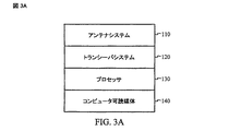
図3aおよび3bは、ユーザ受信機10のブロック図である。相互にすべて電気的に結合されているアンテナシステム110、トランシーバシステム120、プロセッサ130およびコンピュータ可読媒体140を含むユーザ受信機10の第1実施形態が図3aに示されている。アンテナシステム110は、2つの物理的アンテナ、合成開口アンテナまたは連続除去を利用する単一アンテナを含むことができる。図3bは、アンテナシステム110およびトランシーバシステム120を含むユーザ受信機10の第2実施形態を示す。さらに、集積回路150は、アンテナシステム110およびトランシーバシステム120に電気的に結合されている。集積回路150は、プロセッサおよびメモリシステム、FPGA(フィールドプログラマブルゲートアレイ)、ASIC(特定用途向け集積回路)またはそれらの同等物を使用して実装されることもできることを当業者は理解するであろう。
FIGS. 3 a and 3 b are block diagrams of the
一実施形態では、干渉除去アルゴリズムは、代数固有値(algebraic eigenvalues)を使用して干渉除去のために最適のアンテナ重み成分w1およびw2を決定する(「固有値処理」)。ここで、2つのアンテナまたはその同等物を有する移動体ユーザなどのユーザシステムのための固有値処理が説明される。アンテナ#1およびアンテナ#2に関するベースバンド複素(complex)電圧間の複素相関について考察する。複素相関(complex-correlation)は複素値行列(complex valued matrix)を特徴とする:
![]()
![]()
式中、iおよびjはそれぞれ値1または2を取ることができ、IQデータ(時間,1)はアンテナ#1に関する複素電圧サンプルの時系列であり、IQデータ(時間,2)はアンテナ#2に関する複素電圧サンプルの時系列であり、N時間は合計の時間サンプルの合計数であり、sum_timeは全時間の複素合計であり、X’はXの複素共役を示す。ρ(1,1)、ρ(1,2)、ρ(2,1)、およびρ(2,2)は全部合わせて2X2相関行列ρを定義する。
ρは2つの固有ベクトルを有する2つの実数の、正の固有値を有する。2つのアンテナ(アンテナ#1およびアンテナ#2)からのIQストリームの「ビーム形成」組合せについて考察する:
![]()
ρ has two real, positive eigenvalues with two eigenvectors. Consider a “beamforming” combination of IQ streams from two antennas (
![]()
したがって、w1およびw2がρの正規直交固有ベクトルの成分である場合、IQデータC(時間)の平均エネルギーは、|w1|2+|w2|2=1という制約の下で最低値および最大値にある。すなわち、最低エネルギーは1つの固有ベクトルから選択されたw1およびw2に関して生じ、最大値はもう1つの固有ベクトルから選択されたw1およびw2に関して生じる。 Therefore, when w 1 and w 2 are components of orthonormal eigenvectors of ρ, the average energy of IQ data C (time) is the lowest value under the constraint that | w 1 | 2 + | w 2 | 2 = 1. And is at the maximum. That is, the lowest energy occurs with regard w 1 and w 2 selected from one eigenvector, the maximum value occurs with respect to w 1 and w 2 which is selected from another eigenvector.
ビーム形成に関して線形結合について説明すると、1つの固有値がビームを(できるだけ)到来(incoming)無線エネルギーの方に向けるアンテナ重み成分を与え、もう1つの固有値がビームを(できるだけ)到来無線エネルギーから離れた方に向ける直交ビームを与える。低いほうの固有ベクトルは、小さいほうの固有値に対応する固有ビーム(eigenbeam)を表す。高いほうの固有ベクトルは大きいほうの固有値に対応する固有ビームを表す。高いほうの固有ベクトルは2つの単一アンテナ(別々にアンテナ#1およびアンテナ#2)のいずれかに非常に似ているように見える。
Describing a linear combination with respect to beamforming, one eigenvalue gives an antenna weight component that directs the beam towards (as much as possible) incoming radio energy, and another eigenvalue is (as far as possible) away from the incoming radio energy. Gives an orthogonal beam pointing in the direction. The lower eigenvector represents the eigenbeam corresponding to the smaller eigenvalue. The higher eigenvector represents the eigenbeam corresponding to the larger eigenvalue. The higher eigenvector appears to be very similar to either of the two single antennas (separately
表1は、ベースライン、干渉除去(IC)アルゴリズム(固有値処理を使用)、PNオフセットの探索残余リスト(RE)アルゴリズムおよび高感度パイロット探索(IS)アルゴリズムなど、様々なアルゴリズムの性能を分析するために使用される12組のデータを列挙する。ベースラインアルゴリズムでは、3072のチップコヒーレント積分があり、それらのうちの32が積分された合計98304(3PNロール(rolls))に関してインコヒーレントに合計されている。処理ソフトウェアがEc/Io>−33dBのフル探索閾値ごとに10−5誤警報レベルを計算する。(Ecはジュール単位のチップごとのエネルギーに等しく、Ioは1Hzあたりのワット単位の干渉雑音密度に等しい。)IS(高感度パイロット探索)アルゴリズムでは、98304のチップコヒーレント積分があり、フルドップラー探索を伴い、インコヒーレント合計を伴わない。処理ソフトウェアは、Ec/Io>−37dBのフル探索閾値ごとに10−5誤警報レベルを計算する。

ベースライン積分とIS積分は両方とも、80msまたは3PNロールのデータに対応する、同じ数のチップ、98304に関する。信号が(移動体ユーザが移動している場合)それでもなお発見されることができるように、長いコヒーレント積分によるドップラー探索が必要とされる。インコヒーレント対コヒーレントドップラー探索に関する信号対雑音比(SNR)の改善は理論的に約√32または7.5dBであるはずである。しかし、コヒーレント積分とインコヒーレント積分との間の様々な次数のχ2統計値のため、コヒーレント積分の7.5dB効果は、非常に低い誤警報率でたった4dBまで低減される。 Both baseline integration and IS integration relate to the same number of chips, 98304, corresponding to 80 ms or 3 PN roll data. A Doppler search with long coherent integration is required so that the signal can still be found (if the mobile user is moving). The improvement in signal to noise ratio (SNR) for incoherent to coherent Doppler search should theoretically be about √32 or 7.5 dB. However, due to the various orders of χ 2 statistics between coherent and incoherent integration, the 7.5 dB effect of coherent integration is reduced to only 4 dB with a very low false alarm rate.
高いほうの固有ベクトルは、合計のエネルギーを最大化するようなやり方でアンテナ電圧信号を追加する。対照的に、低いほうの固有ベクトルは、合計のエネルギーを最小化するようなやり方でアンテナ電圧信号を追加する。 The higher eigenvector adds the antenna voltage signal in such a way as to maximize the total energy. In contrast, the lower eigenvector adds the antenna voltage signal in such a way as to minimize the total energy.
移動体ユーザが基地局に近い状況について考察する。基地局は、ここではナビゲーションビーコンとして使用されている。2つのアンテナ(アンテナ#1とアンテナ#2)の間の信号の相関は大きく、各アンテナで受信された優勢な近くの基地局ナビゲーションビーコン信号から生じる。高いほうの固有ベクトルは、2つのアンテナ(アンテナ#1およびアンテナ#2)を強いソースに向かってビーム形成する傾向がある。低いほうの固有ベクトルは、対照的に、ビームヌル(たとえばビーム最小)を強い信号ソースの方に向ける傾向がある。高いほうの固有ベクトルは、この組合せからのPPMs(パイロット位相測定値)が各個々のアンテナ(それぞれアンテナ#1およびアンテナ#2)で受信されるものに非常に似ているので、限界便益を有すると予期される。PPMsは、基地局が三辺測量システムでナビゲーションビーコンとして使用されることができるようにする基地局からの信号の時間遅延測定値を提供する。しかし、低いほうの固有ベクトルは、アンテナビームが優勢な近くの基地局ナビゲーションビーコン信号を最小化するように形成されるようにする。最適組合せによって部分的に除去されたこのナビゲーションビーコン信号によって、より弱いナビゲーションビーコン信号は、優勢な近くの基地局ナビゲーションビーコン信号と移動体ユーザから(ビーム形成の点で)同じ方向にない限り、サーチャで分解されることができる。
Consider the situation where a mobile user is close to a base station. The base station is used here as a navigation beacon. The correlation of the signals between the two antennas (
チャネル5および10は、2つの固有ベクトルの解を(等しい雑音レベルに関して基準化した(scaling)後で)インコヒーレントに合計することにより形成される。これはSNRsを高めないはずである。しかし、非常に低い誤警報率では、χ2統計値の次数を上げることによって、検出のより低い閾値が生じる可能性がある。
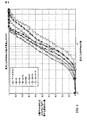
図4は、チャネル7および8の検出されたPPMsのヒストグラムである。チャネル7は、単一ホイップアンテナの場合である。チャネル8(「干渉除去チャネル」)は、低いほうの固有ベクトルを使用する。チャネル7の単一ホイップアンテナは、チャネル7および8からのPPMsの結合(union)を含む合成チャネルを生成するために干渉除去の低いほうの固有ベクトルチャネル(チャネル8)と結合される。両方のチャネルが特定のPNオフセットでPPMを検出した場合、高いほうの値のEc/Ioを有するPPMだけが保持される。干渉除去チャネル(チャネル8)は、Ec/Io>−36dBに関する改善を有効に有しない。しかし、−36dBより下では、干渉除去チャネルは何百ものPPMsを追加する。干渉除去チャネル(チャネル8)によって追加されたPPMsは、隣接リストと残余リストとの間でほぼ等しく分配される。
FIG. 4 is a histogram of detected PPMs for
図5は、チャネル5ならびにチャネル2および3の結合セットに関する検出されたPPMsのヒストグラムである。図5は両方の固有ベクトル(チャネル5)に関するインコヒーレント合計を単一アンテナ(チャネル2)および低いほうの固有ベクトル「干渉除去」固有ベクトル(チャネル3)の組合せと比較する。両方の固有ベクトル(チャネル5)に関するインコヒーレント合計を形成する場合、最も強いEc/Io値がシフトダウンされるが、PPMsはそれでもなお含まれる。したがって、様々なチャネルの最適組合せをどのように得るかは、図5からは、はっきりとは明らかではない。表2は、合成合計チャネルを含めて、各チャネルに関するPPMsの合計数をまとめたものである。表2は、両方の固有ベクトル(チャネル5)に関するインコヒーレント合計と、単一アンテナ(チャネル2)および低いほうの固有ベクトル「干渉除去」固有ベクトル(チャネル3)の組合せとの間のPPMsの数における違いは事実上ないことを示す。表2に示されている例では、チャネル2の残余リストを追加することはPPMsを38%増加させる。
表3は様々なチャネルに関するチャネル2(インコヒーレント合計を使用する単一ホイップアンテナ)のPPMsの数の改善をまとめたものである。表3に示されているように、ベースラインとしてチャネル2で隣接リストだけを使用すると、チャネル7(単一ホイップアンテナでのコヒーレント+ドップラー)に関するPPMsの数の改善は15%である。隣接リストとは、セルラ電話が通信目的で探す基地局のリストのことを表す。残余リストは、電話機が通常は探索しないその他の基地局を表す。残余リストが含まれている場合、改善は25%である。さらに、表3に示されているように、チャネル2をベースラインとして、隣接リストだけを使用すると、チャネル5(2つのアンテナ)に関するPPMsの数の改善は19%である。残余リストが含まれる場合、改善は27%である。チャネル5の結果は、チャネル2+3の場合と同じである。表3に示されているように、チャネル2をベースラインとして、隣接リストだけを使用すると、チャネル7+8に関するPPMsの数の改善は33%である。残余リストが含まれる場合、改善は55%である。
表4は、様々なチャネルに関するチャネル7(長いコヒーレント+ドップラー探索の単一ホイップアンテナ)に関するPPMsの数の改善をまとめたものである。表4に示されているように、隣接リストだけを使用し、2つのアンテナ(チャネル7+8)を使用すると、PPMsの数の改善は16%である。残余リストが含まれる場合、改善は24%である。
図6は、調査された例示的サブセットのチャネルに関する定点ごとのPPMsの数の実験上のCDFを示す。表5は、調査された同じ例示的サブセットのチャネルに関する4以下のPPMsのCDFパーセンタイルをリストアップする。図5は、4以下のPPMsを有していた定点の20%の半分より多くが、REおよびISアルゴリズムの単一アンテナ特徴だけを使用して4PPMsより多くにシフトされることを示す。図5に示されているように、ISアルゴリズムだけは、より多くのPPMsを検出する際にREアルゴリズムだけを使用するのに比べて約2倍効果的である。さらに、ISアルゴリズムとREアルゴリズムを合わせたものはそれぞれ別々のものの合計より良い。表5からの顕著な特徴は、2アンテナ干渉除去(IC)アルゴリズムはそれだけで、単一アンテナを使用するその他の2つのアルゴリズム(REまたはIS)のいずれよりも効果的であることである。さらに表5に示されているように、ICアルゴリズムと組み合わされたREアルゴリズムはREアルゴリズムをISアルゴリズムと結合するより多くの改善を追加する。3つすべてのアルゴリズム(IC、REおよびIS)の組合せは、全体で93%の改善をもたらす。
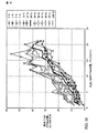
PPMsの小さな数から始まる定点に関する定点ごとのPPMsの数の改善は、追加のPPMごとの最大の改善が、非常に少ないPPMsから始まっている場合に得られることが示されているので興味深い。全CDFにわたるプロットは、1つの変数(たとえば、何らかの改善下の定点ごとのPPMsの数)のCDFが、ベースラインフォーマットに関する定点ごとのPPMsの数など何らかの他の変数を条件にそこからプロットされることができるプロットである。図7〜10は、RSアルゴリズム、ISアルゴリズムまたはICアルゴリズムだけ、または様々な組合せに関する定点ごとのPPMsの数をベースラインフォーマットの定点ごとのPPMsの数と比較する。図7に示されているように、ICアルゴリズムは、低いPPM数の定点においても、定点ごとのPPMsの最大の改善を追加する。図8では、ICアルゴリズムとISアルゴリズムの両方が利用されている。図8に示されているように、ベースライン定点全体にわたって定点ごとのPPMsの数が非常に顕著に増大している。図9では、ICアルゴリズムとREアルゴリズムの両方が利用されている。定点ごとの低いPPMsでは、改善は約2〜3PPMsであるが、定点ごとの高いPPMsでは改善が増大している。図10では、ICアルゴリズム、REアルゴリズムおよびISアルゴリズムが利用されている。図10に示されているように、各定点に追加された平均の改善は約5〜6PPMsであり、より高いPPM数の定点において改善が増大している。2アンテナ干渉除去(IC)アルゴリズムは、低いPPM数の定点を50%より大きく改善する。ICアルゴリズムがREアルゴリズムおよびISアルゴリズムと組合せて追加された場合、改善は、表5に示されているように、93%である。 The improvement in the number of PPMs per fixed point for fixed points starting from a small number of PPMs is interesting as it has been shown that the maximum improvement per additional PPM is obtained when starting with very few PPMs. A plot over the entire CDF is plotted from which CDF of one variable (eg, the number of PPMs per fixed point under some improvement) is subject to some other variable, such as the number of PPMs per fixed point for the baseline format. Is a plot that can. 7-10 compare the number of PPMs per fixed point for the RS algorithm, IS algorithm or IC algorithm alone, or various combinations with the number of PPMs per fixed point in the baseline format. As shown in FIG. 7, the IC algorithm adds the greatest improvement in PPMs per fixed point even at low PPM number fixed points. In FIG. 8, both the IC algorithm and the IS algorithm are used. As shown in FIG. 8, the number of PPMs per fixed point increases very significantly throughout the baseline fixed point. In FIG. 9, both the IC algorithm and the RE algorithm are used. With low PPMs per fixed point, the improvement is about 2-3 PPMs, but with higher PPMs per fixed point, the improvement is increasing. In FIG. 10, an IC algorithm, an RE algorithm, and an IS algorithm are used. As shown in FIG. 10, the average improvement added to each fixed point is about 5-6 PPMs, with the improvement increasing at higher PPM number fixed points. The two antenna interference cancellation (IC) algorithm improves the fixed point of low PPM number by more than 50%. If the IC algorithm is added in combination with the RE and IS algorithms, the improvement is 93%, as shown in Table 5.
干渉除去アルゴリズムの第2実施形態は、簡略化された処理を使用する。アンテナ重み成分は、最も強いナビゲーションビーコン信号を正確に除去するために各アンテナで受信された最も強いナビゲーションビーコン信号の測定値に基づいて選択される。a1およびa2が2つのアンテナ(アンテナ#1およびアンテナ#2)のそれぞれでの最も強いナビゲーションビーコン信号の複素電圧とすると、w1=−a1およびw2=a2のような最強ナビゲーションビーコン信号を除去するためにアンテナ重み成分w1=−a1およびw2=a2を設定する。ここで、w1*a1+w2*a2はゼロに等しく、最も強いナビゲーションビーコン信号を除去する。マルチプルの強いナビゲーションビーコン信号がある場合、できるだけ多くのマルチプルの強いナビゲーションビーコン信号を除去するように複素アンテナ重み成分を設定する。3つの強いナビゲーションビーコン信号を使用する例では、アンテナ#1によって受信された3つの強いナビゲーションビーコン信号の複素電圧がx1、y1およびz1であり、アンテナ#2によって受信された3つの強いナビゲーションビーコン信号がx2、y2およびz2であると仮定する。アンテナ#1での複素電圧の合計がS1=x1+y1+z1であり、アンテナ#2での複素電圧の合計がS2=x2+y2+z2であるとすると、アンテナ重み成分w1およびw2は、他のより弱いナビゲーションビーコン信号がアンテナによって検出可能であるように適当なトレードオフで3つの強いナビゲーションビーコン信号を除去するためにw1=−S2およびw2=S1に設定されるべきである。例ではアンテナ重み成分を計算するために特定の数式が示されているが、他の数式が本発明の範囲を侵害することなくアンテナ重み成分のために使用されることができることを当業者は理解するであろう。さらに、本発明は特定の数の強いナビゲーションビーコン信号だけを除去することに限定されないことを当業者は理解しているであろう。そうではなく、所望の数の強いナビゲーションビーコン信号を除去するためにアンテナ重み成分を複数の強いナビゲーションビーコン信号の複素電圧の合計に適用することが当業者には理解されているであろう。
The second embodiment of the interference cancellation algorithm uses a simplified process. The antenna weight component is selected based on measurements of the strongest navigation beacon signal received at each antenna to accurately remove the strongest navigation beacon signal. When a 1 and a 2 is the complex voltage of the strongest navigation beacon signal at each of the two antennas (
さらに、2つの物理的アンテナを有する必要はない。異なる時点に受信された測定値を、それらがあたかも同時に2つの別々のアンテナによって受信された2つの異なる測定値であるかのように捕捉する単一アンテナは、合成開口アンテナとして知られている。合成開口アンテナは、より強いナビゲーションビーコン信号によってマスクされる可能性のあるナビゲーションビーコン信号を検出するために干渉除去アルゴリズムを用いて使用されることができる。合成開口アンテナを使用する場合、異なる時点に1つの物理的アンテナによって受信されたナビゲーションビーコン信号は、あたかもそれらが同時に受信されたかのように結合されるので、2つの仮想アンテナ(仮想アンテナ#1および仮想アンテナ#2)があると仮定する。たとえば、仮想アンテナ#1は、時間t1とt1+dとの間に到着するパイロットバーストから成ることができ、一方仮想アンテナ#2は、しばらく後で--時間t3とt3+dとの間に到着するパイロットバーストから成ることができる。時間t1およびt3は、整数のPNロールによって異なる。パイロットバーストは正確にPNロールごとに一度繰り返して起こるので、時間で整数のPNロールによって分離された2つのパイロットバーストからのナビゲーションビーコン信号は、空間で分離された2つのアンテナによって受信された同時のナビゲーションビーコン信号に似ている。2つの時間t1およびt3が定義されると、(前述のように)2つの物理的アンテナの場合に適用可能なすべての組合せ処理が適用されることができる。
Furthermore, it is not necessary to have two physical antennas. A single antenna that captures measurements received at different times as if they were two different measurements received by two separate antennas simultaneously is known as a synthetic aperture antenna. Synthetic aperture antennas can be used with interference cancellation algorithms to detect navigation beacon signals that may be masked by stronger navigation beacon signals. When using synthetic aperture antennas, navigation beacon signals received by one physical antenna at different times are combined as if they were received simultaneously, so two virtual antennas (
さらに、1つの物理的アンテナを使用する「連続除去」の使用は、ナビゲーションビーコン信号を検出するために干渉除去アルゴリズムを用いて使用されることができる。ここで、受信機がナビゲーションビーコン信号のコピーを記憶する。受信機が非常に強く受信するナビゲーションビーコン信号では、記憶されたナビゲーションビーコン信号の時間遅延が、空間ダイバーシティをエミュレートするために実際に受信された強いナビゲーションビーコン信号の時間遅延に一致するように設定されている限り、受信機は記憶されたナビゲーションビーコン信号をあたかも第2「仮想アンテナ」から来たように扱うことができる。したがって、固有値または簡略化された処理のいずれかを使用して、強いナビゲーションビーコン信号が効果的に除去されることができ、したがって、マスクされたより弱いナビゲーションビーコン信号が受信されることができる。この「連続除去」技法の使用は、最も強いナビゲーションビーコン信号を除去し、次いで第2に強いナビゲーションビーコン信号を、次いで第3に強いナビゲーションビーコン信号を除去し、その他同様にして、より弱いナビゲーションビーコン信号に対する所望のレベルの感度が実現されるまで、成功裏に利用されることができることが当業者によって理解されるであろう。 Furthermore, the use of “continuous cancellation” using one physical antenna can be used with an interference cancellation algorithm to detect navigation beacon signals. Here, the receiver stores a copy of the navigation beacon signal. For navigation beacon signals that the receiver receives very strongly, the time delay of the stored navigation beacon signal is set to match the time delay of the strong navigation beacon signal actually received to emulate spatial diversity As long as it is, the receiver can treat the stored navigation beacon signal as if it came from the second “virtual antenna”. Thus, using either eigenvalues or simplified processing, strong navigation beacon signals can be effectively removed, and thus masked weaker navigation beacon signals can be received. The use of this “continuous cancellation” technique eliminates the strongest navigation beacon signal, then the second strongest navigation beacon signal, then the third strongest navigation beacon signal, and so on, and the weaker navigation beacons. It will be appreciated by those skilled in the art that a desired level of sensitivity to a signal can be successfully utilized until it is achieved.
開示された諸実施形態の前述の説明は、本発明を当業者なら誰でも作成または使用することができるようにするために提供されている。これらの実施形態に対する様々な変更形態が当業者には容易に明らかになるであろうし、本明細書で定義された一般的原理は、本発明の趣旨および範囲から逸脱することなく、他の諸実施形態に適用されることができる。 The previous description of the disclosed embodiments is provided to enable any person skilled in the art to make or use the present invention. Various modifications to these embodiments will be readily apparent to those skilled in the art, and the generic principles defined herein may be modified in other ways without departing from the spirit and scope of the invention. It can be applied to the embodiment.
Claims (21)
2つの異なる測定値を受信するために2つのアンテナを使用すること、および
干渉除去ビームを形成するために2つのアンテナ重み成分を使用して前記2つの異なる測定値を結合すること
を具備する方法。 A method for detecting a plurality of navigation beacon signals, comprising:
Using two antennas to receive two different measurements, and combining the two different measurements using two antenna weight components to form an interference cancellation beam .
複数の異なる測定値を受信するために1つの合成開口アンテナを使用すること、および
干渉除去ビームを形成するために複数のアンテナ重み成分を使用して前記複数の異なる測定値を結合すること
を具備する方法。 A method for detecting a plurality of navigation beacon signals, comprising:
Using a single synthetic aperture antenna to receive a plurality of different measurements and combining the plurality of different measurements using a plurality of antenna weight components to form an interference cancellation beam. how to.
最初に受信される測定値を受信するために1つのアンテナを使用すること、
前記最初に受信された測定値のコピーを作成し、処理されたコピーになるように空間ダイバーシティをエミュレートするために時間遅延を一致させることにより前記最初に受信された測定値の前記コピーを処理すること、および
干渉除去ビームを形成するために2つのアンテナ重み成分を使用して前記最初に受信された測定値を前記処理されたコピーと結合すること
を具備する方法。 A method for detecting a plurality of navigation beacon signals, comprising:
Using one antenna to receive the first received measurement,
Create a copy of the first received measurement and process the copy of the first received measurement by matching time delays to emulate spatial diversity to be a processed copy And combining the initially received measurement with the processed copy using two antenna weight components to form an interference cancellation beam.
2つの異なる測定値を受信するために2つのアンテナを使用すること、および
干渉除去ビームを形成するために2つのアンテナ重み成分を使用して前記2つの異なる測定値を結合すること
を具備する、コンピュータ可読媒体。 A computer readable medium incorporating a program of instructions executable by a computer program to implement a method for detecting a plurality of navigation beacon signals, the method comprising:
Using two antennas to receive two different measurements, and combining the two different measurements using two antenna weight components to form an interference cancellation beam; Computer readable medium.
複数の異なる測定値を受信するために1つの合成開口アンテナを使用すること、および
干渉除去ビームを形成するために複数のアンテナ重み成分を使用して前記複数の異なる測定値を結合すること
を具備する、コンピュータ可読媒体。 A computer readable medium incorporating a program of instructions executable by a computer program to implement a method for detecting a plurality of navigation beacon signals, the method comprising:
Using a single synthetic aperture antenna to receive a plurality of different measurements and combining the plurality of different measurements using a plurality of antenna weight components to form an interference cancellation beam. A computer readable medium.
最初に受信される測定値を受信するために1つのアンテナを使用すること、
前記最初に受信された測定値のコピーを作成し、処理されたコピーになるように空間ダイバーシティをエミュレートするために時間遅延を一致させることにより前記最初に受信された測定値の前記コピーを処理すること、および
干渉除去ビームを形成するために2つのアンテナ重み成分を使用して前記最初に受信された測定値を前記処理されたコピーと結合すること
を具備する、コンピュータ可読媒体。 A computer readable medium incorporating a program of instructions executable by a computer program to implement a method for detecting a plurality of navigation beacon signals, the method comprising:
Using one antenna to receive the first received measurement,
Create a copy of the first received measurement and process the copy of the first received measurement by matching time delays to emulate spatial diversity to be a processed copy And combining the initially received measurement with the processed copy using two antenna weight components to form an interference cancellation beam.
2つの異なる測定値を受信するために2つのアンテナを使用すること、および
干渉除去ビームを形成するために2つのアンテナ重み成分を使用して前記2つの異なる測定値を結合すること
を具備する、集積回路。 An integrated circuit for implementing a method for detecting a plurality of navigation beacon signals, the method comprising:
Using two antennas to receive two different measurements, and combining the two different measurements using two antenna weight components to form an interference cancellation beam; Integrated circuit.
複数の異なる測定値を受信するために1つの合成開口アンテナを使用すること、
干渉除去ビームを形成するために複数のアンテナ重み成分を使用して前記複数の異なる測定値を結合すること
を具備する、集積回路。 An integrated circuit for implementing a method for detecting a plurality of navigation beacon signals, the method comprising:
Using one synthetic aperture antenna to receive a plurality of different measurements;
Combining said plurality of different measurements using a plurality of antenna weight components to form an interference cancellation beam.
最初に受信される測定値を受信するために1つのアンテナを使用すること、
前記最初に受信された測定値のコピーを作成し、処理されたコピーになるように、空間ダイバーシティをエミュレートするために時間遅延を一致させることにより前記最初に受信された測定値の前記コピーを処理すること、および
干渉除去ビームを形成するために2つのアンテナ重み成分を使用して前記最初に受信された測定値を前記処理されたコピーと結合すること
を具備する、集積回路。 An integrated circuit for implementing a method for detecting a plurality of navigation beacon signals, the method comprising:
Using one antenna to receive the first received measurement,
Make a copy of the first received measurement and make the copy of the first received measurement by matching time delays to emulate spatial diversity to be a processed copy. An integrated circuit comprising: processing and combining the initially received measurement with the processed copy using two antenna weight components to form an interference cancellation beam.
Applications Claiming Priority (3)
| Application Number | Priority Date | Filing Date | Title |
|---|---|---|---|
| US68045405P | 2005-05-11 | 2005-05-11 | |
| US11/165,281 US7362268B2 (en) | 2005-05-11 | 2005-06-22 | Method for detecting navigation beacon signals using two antennas or equivalent thereof |
| PCT/US2006/018605 WO2006122316A2 (en) | 2005-05-11 | 2006-05-11 | Method for detecting navigation beacon signals using two antennas or equivalent thereof |
Related Child Applications (1)
| Application Number | Title | Priority Date | Filing Date |
|---|---|---|---|
| JP2012219358A Division JP5591895B2 (en) | 2005-05-11 | 2012-10-01 | Method for detecting navigation beacon signals using two antennas or the like |
Publications (2)
| Publication Number | Publication Date |
|---|---|
| JP2008545299A true JP2008545299A (en) | 2008-12-11 |
| JP2008545299A5 JP2008545299A5 (en) | 2012-02-02 |
Family
ID=37397346
Family Applications (3)
| Application Number | Title | Priority Date | Filing Date |
|---|---|---|---|
| JP2008511447A Withdrawn JP2008545299A (en) | 2005-05-11 | 2006-05-11 | Method for detecting navigation beacon signals using two antennas or the like |
| JP2012219358A Expired - Fee Related JP5591895B2 (en) | 2005-05-11 | 2012-10-01 | Method for detecting navigation beacon signals using two antennas or the like |
| JP2013256482A Pending JP2014090461A (en) | 2005-05-11 | 2013-12-11 | Method for detecting navigation beacon signals using two antennas or equivalent thereof |
Family Applications After (2)
| Application Number | Title | Priority Date | Filing Date |
|---|---|---|---|
| JP2012219358A Expired - Fee Related JP5591895B2 (en) | 2005-05-11 | 2012-10-01 | Method for detecting navigation beacon signals using two antennas or the like |
| JP2013256482A Pending JP2014090461A (en) | 2005-05-11 | 2013-12-11 | Method for detecting navigation beacon signals using two antennas or equivalent thereof |
Country Status (6)
| Country | Link |
|---|---|
| US (2) | US7362268B2 (en) |
| EP (1) | EP1889090A4 (en) |
| JP (3) | JP2008545299A (en) |
| KR (1) | KR100979608B1 (en) |
| CN (3) | CN102608572B (en) |
| WO (1) | WO2006122316A2 (en) |
Cited By (2)
| Publication number | Priority date | Publication date | Assignee | Title |
|---|---|---|---|---|
| JP2008306662A (en) * | 2007-06-11 | 2008-12-18 | Nippon Telegr & Teleph Corp <Ntt> | Transmitting/receiving device and communication method thereof |
| JP2012531592A (en) * | 2009-06-24 | 2012-12-10 | クゥアルコム・インコーポレイテッド | Receive diversity in GNSS receiver |
Families Citing this family (9)
| Publication number | Priority date | Publication date | Assignee | Title |
|---|---|---|---|---|
| DE102005000732A1 (en) * | 2005-01-04 | 2006-07-13 | Siemens Ag | Radio-based location system with synthetic aperture |
| US7362268B2 (en) * | 2005-05-11 | 2008-04-22 | Qualcomm Inc | Method for detecting navigation beacon signals using two antennas or equivalent thereof |
| US8112358B2 (en) * | 2007-06-04 | 2012-02-07 | Qualcomm Atheros, Inc. | Authorizing customer premise equipment on a sub-network |
| US8019221B2 (en) * | 2007-08-02 | 2011-09-13 | Zoran Corporation | Systems and methods for broadband transmission of signals |
| WO2016127028A1 (en) * | 2015-02-05 | 2016-08-11 | Commscope Technologies Llc | Systems and methods for emulating uplink diversity signals |
| CN104865586B (en) * | 2015-06-15 | 2017-03-22 | 中国人民解放军国防科学技术大学 | Method for realizing interference resistance and multipath restraint of navigation receiver with array antenna |
| FR3046324B1 (en) * | 2015-12-23 | 2018-12-14 | Sagemcom Broadband Sas | METHOD FOR DETERMINING A TIME REFERENCE AND / OR AT LEAST ONE SPATIAL REFERENCE IN A COMMUNICATION SYSTEM |
| US20200333429A1 (en) * | 2017-12-29 | 2020-10-22 | Ubicquia Iq Llc | Sonic pole position triangulation in a lighting system |
| US11550062B2 (en) | 2019-12-24 | 2023-01-10 | All.Space Networks Ltd. | High-gain multibeam GNSS antenna |
Citations (7)
| Publication number | Priority date | Publication date | Assignee | Title |
|---|---|---|---|---|
| JPS6122274A (en) * | 1984-07-11 | 1986-01-30 | Natl Space Dev Agency Japan<Nasda> | Method for data processing of synthetic aperture radar |
| JP2002064331A (en) * | 2000-08-21 | 2002-02-28 | Nec Corp | Multibeam antenna system |
| JP2002507071A (en) * | 1998-03-12 | 2002-03-05 | インターデイジタル テクノロジー コーポレーション | Adaptive Canceller with Fixed Interference Source |
| JP2002314470A (en) * | 2001-04-18 | 2002-10-25 | Kddi Corp | Transmission/reception frequency division multiplex wireless equipment |
| JP2004072427A (en) * | 2002-08-06 | 2004-03-04 | Matsushita Electric Ind Co Ltd | Radio transmitter and radio transmission method |
| JP2004297483A (en) * | 2003-03-27 | 2004-10-21 | Kyocera Corp | Mobile station, and communication control method |
| JP2006500832A (en) * | 2002-09-23 | 2006-01-05 | テンソルコム インコーポレイテッド | Method and apparatus for selectively utilizing interference cancellation in a spread spectrum system |
Family Cites Families (13)
| Publication number | Priority date | Publication date | Assignee | Title |
|---|---|---|---|---|
| US4387373A (en) * | 1977-04-21 | 1983-06-07 | Westinghouse Electric Corp. | Synthetic monopulse radar |
| DE3005928A1 (en) * | 1980-02-16 | 1981-09-10 | Robert Bosch Gmbh, 7000 Stuttgart | HEATED ION CURRENT PROBE FOR HIGH CEMPERATURES |
| US4546355A (en) * | 1982-06-17 | 1985-10-08 | Grumman Aerospace Corporation | Range/azimuth/elevation ship imaging for ordnance control |
| US4794395A (en) * | 1987-04-17 | 1988-12-27 | Environmental Research Institute Of Mich. | Passive interferometric imaging receiver system |
| US4978961A (en) * | 1989-12-21 | 1990-12-18 | Hughes Aircraft Company | Synthetic aperture radar with dead-ahead beam sharpening capability |
| US5515378A (en) * | 1991-12-12 | 1996-05-07 | Arraycomm, Inc. | Spatial division multiple access wireless communication systems |
| JP2853742B2 (en) * | 1997-06-10 | 1999-02-03 | 日本電気株式会社 | Direct Spread / Code Division Multiplexing Interference Cancellation Receiver |
| DE60039637D1 (en) * | 2000-10-06 | 2008-09-04 | Nokia Corp | DECORATED PARALLEL INTERFERENCE SUPPRESSION FOR CDMA SYSTEMS |
| US6745050B1 (en) * | 2000-10-23 | 2004-06-01 | Massachusetts Institute Of Technology | Multichannel multiuser detection |
| KR20030050338A (en) | 2001-12-18 | 2003-06-25 | 엘지전자 주식회사 | Method for updating weighted vector |
| US7012978B2 (en) * | 2002-03-26 | 2006-03-14 | Intel Corporation | Robust multiple chain receiver |
| US6844850B1 (en) * | 2004-05-20 | 2005-01-18 | Benq Corporation | Anti-jammer pre-processor |
| US7362268B2 (en) * | 2005-05-11 | 2008-04-22 | Qualcomm Inc | Method for detecting navigation beacon signals using two antennas or equivalent thereof |
-
2005
- 2005-06-22 US US11/165,281 patent/US7362268B2/en active Active
-
2006
- 2006-05-11 WO PCT/US2006/018605 patent/WO2006122316A2/en active Application Filing
- 2006-05-11 EP EP06759777A patent/EP1889090A4/en not_active Withdrawn
- 2006-05-11 KR KR1020077028911A patent/KR100979608B1/en active IP Right Grant
- 2006-05-11 CN CN201210085448.9A patent/CN102608572B/en not_active Expired - Fee Related
- 2006-05-11 JP JP2008511447A patent/JP2008545299A/en not_active Withdrawn
- 2006-05-11 CN CN201310361688.1A patent/CN103401597B/en not_active Expired - Fee Related
- 2006-05-11 CN CN2006800243702A patent/CN101495884B/en not_active Expired - Fee Related
-
2008
- 2008-04-04 US US12/098,323 patent/US7859461B2/en not_active Expired - Fee Related
-
2012
- 2012-10-01 JP JP2012219358A patent/JP5591895B2/en not_active Expired - Fee Related
-
2013
- 2013-12-11 JP JP2013256482A patent/JP2014090461A/en active Pending
Patent Citations (7)
| Publication number | Priority date | Publication date | Assignee | Title |
|---|---|---|---|---|
| JPS6122274A (en) * | 1984-07-11 | 1986-01-30 | Natl Space Dev Agency Japan<Nasda> | Method for data processing of synthetic aperture radar |
| JP2002507071A (en) * | 1998-03-12 | 2002-03-05 | インターデイジタル テクノロジー コーポレーション | Adaptive Canceller with Fixed Interference Source |
| JP2002064331A (en) * | 2000-08-21 | 2002-02-28 | Nec Corp | Multibeam antenna system |
| JP2002314470A (en) * | 2001-04-18 | 2002-10-25 | Kddi Corp | Transmission/reception frequency division multiplex wireless equipment |
| JP2004072427A (en) * | 2002-08-06 | 2004-03-04 | Matsushita Electric Ind Co Ltd | Radio transmitter and radio transmission method |
| JP2006500832A (en) * | 2002-09-23 | 2006-01-05 | テンソルコム インコーポレイテッド | Method and apparatus for selectively utilizing interference cancellation in a spread spectrum system |
| JP2004297483A (en) * | 2003-03-27 | 2004-10-21 | Kyocera Corp | Mobile station, and communication control method |
Cited By (4)
| Publication number | Priority date | Publication date | Assignee | Title |
|---|---|---|---|---|
| JP2008306662A (en) * | 2007-06-11 | 2008-12-18 | Nippon Telegr & Teleph Corp <Ntt> | Transmitting/receiving device and communication method thereof |
| JP4673869B2 (en) * | 2007-06-11 | 2011-04-20 | 日本電信電話株式会社 | Transceiver and communication method thereof |
| JP2012531592A (en) * | 2009-06-24 | 2012-12-10 | クゥアルコム・インコーポレイテッド | Receive diversity in GNSS receiver |
| US8736490B2 (en) | 2009-06-24 | 2014-05-27 | Qualcomm Incorporated | Receive diversity in GNSS receivers |
Also Published As
| Publication number | Publication date |
|---|---|
| US20080186230A1 (en) | 2008-08-07 |
| EP1889090A2 (en) | 2008-02-20 |
| US7859461B2 (en) | 2010-12-28 |
| WO2006122316A3 (en) | 2009-04-23 |
| CN103401597A (en) | 2013-11-20 |
| US20060256009A1 (en) | 2006-11-16 |
| JP5591895B2 (en) | 2014-09-17 |
| JP2013047684A (en) | 2013-03-07 |
| KR100979608B1 (en) | 2010-09-01 |
| JP2014090461A (en) | 2014-05-15 |
| CN102608572A (en) | 2012-07-25 |
| WO2006122316A2 (en) | 2006-11-16 |
| KR20080019613A (en) | 2008-03-04 |
| CN101495884A (en) | 2009-07-29 |
| CN101495884B (en) | 2013-10-30 |
| CN103401597B (en) | 2015-11-18 |
| EP1889090A4 (en) | 2012-11-21 |
| CN102608572B (en) | 2015-05-06 |
| US7362268B2 (en) | 2008-04-22 |
Similar Documents
| Publication | Publication Date | Title |
|---|---|---|
| JP5591895B2 (en) | Method for detecting navigation beacon signals using two antennas or the like | |
| US9084217B2 (en) | Single-site localization via multipath fingerprinting | |
| US8340588B2 (en) | Handheld synthetic antenna array | |
| Kupershtein et al. | Single-site emitter localization via multipath fingerprinting | |
| CN106909779B (en) | MIMO radar Cramér-Rao lower bound calculation method based on distributed treatment | |
| WO2018160141A1 (en) | Apparatus and method for localisation and/or tracking | |
| Broumandan et al. | Indoor GNSS signal acquisition performance using a synthetic antenna array | |
| US11754658B2 (en) | Radio station for client localization in multipath indoor environment | |
| Elhag et al. | Angle of arrival estimation in smart antenna using MUSIC method for wideband wireless communication | |
| Broumandan et al. | A network-based GNSS structural interference detection, classification and source localization | |
| Haniz et al. | A novel phase-difference fingerprinting technique for localization of unknown emitters | |
| Xiong | Pushing the limits of indoor localization in today’s Wi-Fi networks | |
| US11005507B2 (en) | Targeted ratio of signal power to interference plus noise power for enhancement of a multi-user detection receiver | |
| JP4980548B2 (en) | Method and apparatus for determining operating conditions in a communication system | |
| Malla et al. | Design and analysis of direction of arrival using hybrid expectation-maximization and MUSIC for wireless communication | |
| KR101406349B1 (en) | METHOD AND APPARATUS OF ESTIMATING CELL ID AND DoA IN MULTI PATH ENVIRONMENT | |
| JP6747688B2 (en) | Source estimation method and source estimation apparatus using the same | |
| JP4633667B2 (en) | Array antenna transmitter | |
| JP4147864B2 (en) | Method and receiver for estimating spatial angular spread | |
| Haniz et al. | Hybrid fingerprint-based localization of unknown radios: measurements in an open field | |
| CA2679673A1 (en) | Handheld synthetic antenna array | |
| KR102327993B1 (en) | Position Estimation Method Estimating To Position Of Interference Signal Source, And Position Estimation System For Performing The Method | |
| Sun et al. | Maximum likelihood indoor localization of a WiFi radio transmitter with structural knowledge | |
| Amin et al. | Accurate estimation of DOA and MAI mitigation in the presence of channel impairments at low SNR |
Legal Events
| Date | Code | Title | Description |
|---|---|---|---|
| A977 | Report on retrieval |
Free format text: JAPANESE INTERMEDIATE CODE: A971007 Effective date: 20100823 |
|
| A131 | Notification of reasons for refusal |
Free format text: JAPANESE INTERMEDIATE CODE: A131 Effective date: 20100831 |
|
| A601 | Written request for extension of time |
Free format text: JAPANESE INTERMEDIATE CODE: A601 Effective date: 20101130 |
|
| A602 | Written permission of extension of time |
Free format text: JAPANESE INTERMEDIATE CODE: A602 Effective date: 20101207 |
|
| A601 | Written request for extension of time |
Free format text: JAPANESE INTERMEDIATE CODE: A601 Effective date: 20110104 |
|
| A602 | Written permission of extension of time |
Free format text: JAPANESE INTERMEDIATE CODE: A602 Effective date: 20110112 |
|
| A601 | Written request for extension of time |
Free format text: JAPANESE INTERMEDIATE CODE: A601 Effective date: 20110131 |
|
| A602 | Written permission of extension of time |
Free format text: JAPANESE INTERMEDIATE CODE: A602 Effective date: 20110207 |
|
| A521 | Request for written amendment filed |
Free format text: JAPANESE INTERMEDIATE CODE: A523 Effective date: 20110228 |
|
| A131 | Notification of reasons for refusal |
Free format text: JAPANESE INTERMEDIATE CODE: A131 Effective date: 20110823 |
|
| A601 | Written request for extension of time |
Free format text: JAPANESE INTERMEDIATE CODE: A601 Effective date: 20111124 |
|
| A602 | Written permission of extension of time |
Free format text: JAPANESE INTERMEDIATE CODE: A602 Effective date: 20111201 |
|
| A524 | Written submission of copy of amendment under article 19 pct |
Free format text: JAPANESE INTERMEDIATE CODE: A524 Effective date: 20111207 |
|
| A521 | Request for written amendment filed |
Free format text: JAPANESE INTERMEDIATE CODE: A523 Effective date: 20111208 |
|
| A02 | Decision of refusal |
Free format text: JAPANESE INTERMEDIATE CODE: A02 Effective date: 20120529 |
|
| RD04 | Notification of resignation of power of attorney |
Free format text: JAPANESE INTERMEDIATE CODE: A7424 Effective date: 20120529 |
|
| A521 | Request for written amendment filed |
Free format text: JAPANESE INTERMEDIATE CODE: A523 Effective date: 20121001 |
|
| A911 | Transfer to examiner for re-examination before appeal (zenchi) |
Free format text: JAPANESE INTERMEDIATE CODE: A911 Effective date: 20121010 |
|
| A761 | Written withdrawal of application |
Free format text: JAPANESE INTERMEDIATE CODE: A761 Effective date: 20121128 |