JP2008542816A - Audio signal encoding and decoding method - Google Patents
Audio signal encoding and decoding method Download PDFInfo
- Publication number
- JP2008542816A JP2008542816A JP2008513379A JP2008513379A JP2008542816A JP 2008542816 A JP2008542816 A JP 2008542816A JP 2008513379 A JP2008513379 A JP 2008513379A JP 2008513379 A JP2008513379 A JP 2008513379A JP 2008542816 A JP2008542816 A JP 2008542816A
- Authority
- JP
- Japan
- Prior art keywords
- audio signal
- additional information
- spatial information
- embedded
- information
- Prior art date
- Legal status (The legal status is an assumption and is not a legal conclusion. Google has not performed a legal analysis and makes no representation as to the accuracy of the status listed.)
- Pending
Links
Images


Classifications
-
- H—ELECTRICITY
- H04—ELECTRIC COMMUNICATION TECHNIQUE
- H04H—BROADCAST COMMUNICATION
- H04H20/00—Arrangements for broadcast or for distribution combined with broadcast
- H04H20/86—Arrangements characterised by the broadcast information itself
- H04H20/88—Stereophonic broadcast systems
- H04H20/89—Stereophonic broadcast systems using three or more audio channels, e.g. triphonic or quadraphonic
-
- G—PHYSICS
- G10—MUSICAL INSTRUMENTS; ACOUSTICS
- G10L—SPEECH ANALYSIS OR SYNTHESIS; SPEECH RECOGNITION; SPEECH OR VOICE PROCESSING; SPEECH OR AUDIO CODING OR DECODING
- G10L19/00—Speech or audio signals analysis-synthesis techniques for redundancy reduction, e.g. in vocoders; Coding or decoding of speech or audio signals, using source filter models or psychoacoustic analysis
- G10L19/008—Multichannel audio signal coding or decoding using interchannel correlation to reduce redundancy, e.g. joint-stereo, intensity-coding or matrixing
-
- G—PHYSICS
- G10—MUSICAL INSTRUMENTS; ACOUSTICS
- G10L—SPEECH ANALYSIS OR SYNTHESIS; SPEECH RECOGNITION; SPEECH OR VOICE PROCESSING; SPEECH OR AUDIO CODING OR DECODING
- G10L19/00—Speech or audio signals analysis-synthesis techniques for redundancy reduction, e.g. in vocoders; Coding or decoding of speech or audio signals, using source filter models or psychoacoustic analysis
- G10L19/018—Audio watermarking, i.e. embedding inaudible data in the audio signal
-
- G—PHYSICS
- G10—MUSICAL INSTRUMENTS; ACOUSTICS
- G10L—SPEECH ANALYSIS OR SYNTHESIS; SPEECH RECOGNITION; SPEECH OR VOICE PROCESSING; SPEECH OR AUDIO CODING OR DECODING
- G10L19/00—Speech or audio signals analysis-synthesis techniques for redundancy reduction, e.g. in vocoders; Coding or decoding of speech or audio signals, using source filter models or psychoacoustic analysis
- G10L19/04—Speech or audio signals analysis-synthesis techniques for redundancy reduction, e.g. in vocoders; Coding or decoding of speech or audio signals, using source filter models or psychoacoustic analysis using predictive techniques
- G10L19/16—Vocoder architecture
- G10L19/167—Audio streaming, i.e. formatting and decoding of an encoded audio signal representation into a data stream for transmission or storage purposes
Abstract
【課題】オーディオ信号を符号化(encoding)及び復号化(decoding)する方法を提供する。
【解決手段】オーディオ信号を符号化及び復号化する方法を提供するために、ダウンミックス信号に空間情報を埋め込む方法及び装置を提供する。このとき、前記ダウンミックス信号を用いて挿入ビット長を求め、該ダウンミックス信号の挿入ビットに前記空間情報を埋め込む。また、前記ダウンミックス信号に前記空間情報を埋め込むフレーム長を效率的に構成できる方法及び装置を提供する。また、前記空間情報を少なくとも1チャンネルを持つダウンミックス信号に效率的に分割して挿入する方法及び装置を提供する。
【選択図】図24A method for encoding and decoding an audio signal is provided.
To provide a method for encoding and decoding an audio signal, a method and apparatus for embedding spatial information in a downmix signal is provided. At this time, the insertion bit length is obtained using the downmix signal, and the spatial information is embedded in the insertion bit of the downmix signal. The present invention also provides a method and apparatus that can efficiently configure a frame length for embedding the spatial information in the downmix signal. The present invention also provides a method and apparatus for efficiently dividing and inserting the spatial information into a downmix signal having at least one channel.
[Selection] Figure 24
Description
本発明は、オーディオ信号の符号化(encoding)及び復号化(decoding)方法に関する。 The present invention relates to an audio signal encoding and decoding method.
近年、デジタルオーディオ信号に対する様々なコーディング技術及び方法が開発されており、その様々なコーディング技術及び方法と関連した製品も生産されている。また、マルチチャネルオーディオ信号の空間情報を用いてモノまたはステレオオーディオ信号をマルチチャネルオーディオ信号に変えるコーディング方法が開発されてきている。 In recent years, various coding techniques and methods for digital audio signals have been developed, and products related to the various coding techniques and methods have been produced. Also, a coding method has been developed that converts a mono or stereo audio signal into a multichannel audio signal using spatial information of the multichannel audio signal.
しかしながら、オーディオ信号を保存する場合、空間情報を保存できる補助データ領域が存在しない記録媒体がある。したがって、このような場合には、モノまたはステレオオーディオ信号のみを保存または転送することによって、モノまたはステレオオーディオ信号にしか再生されず、音質が単調になる問題点があった。また、空間情報を別個に保存する、または、別個に転送する場合には、一般のモノまたはステレオオーディオ信号の再生器との互換性において問題があった。 However, when storing an audio signal, there is a recording medium that does not have an auxiliary data area in which spatial information can be stored. Therefore, in such a case, only the mono or stereo audio signal is stored or transferred, so that only the mono or stereo audio signal is reproduced and the sound quality becomes monotonous. In addition, when spatial information is stored separately or transferred separately, there is a problem in compatibility with a general mono or stereo audio signal player.
本発明は関連技術の限界や欠点による1つ以上の問題を実質的に排除するオーディオ信号の符号化・復号化装置及び符号化・復号化方法に関する。
その目的は、オーディオ信号のコーディングにおいて、一般のモノまたはステレオオーディオ信号の再生器と互換性を持つ符号化・復号化装置と、符号化及び復号化方法を提供することにある。
本発明の他の目的は、補助データ領域が存在しない場合にもマルチチャネルオーディオ信号に対する空間情報を保存または転送できるようにした符号化・復号化装置と符号化及び復号化方法を提供することにある。
The present invention relates to an audio signal encoding / decoding apparatus and encoding / decoding method that substantially eliminate one or more problems due to limitations and disadvantages of the related art.
An object of the present invention is to provide an encoding / decoding device and an encoding / decoding method compatible with a general mono or stereo audio signal regenerator in coding of an audio signal.
Another object of the present invention is to provide an encoding / decoding device and an encoding / decoding method capable of storing or transferring spatial information for a multi-channel audio signal even when no auxiliary data area exists. is there.
上記の目的を達成するために、本発明は、オーディオ信号成分のうち非知覚的成分に埋め込まれた(embeded)付加情報を抽出する段階と、前記付加情報を用いて前記オーディオ信号をデコーディングする段階と、を含むことを特徴とするオーディオ信号のデコーディング方法を提供する。 To achieve the above object, the present invention extracts the additional information embedded in the non-perceptual component of the audio signal component, and decodes the audio signal using the additional information. And a method for decoding an audio signal.
また、上記の目的を達成するために、本発明は、前記オーディオ信号をデコーディングするのに必要な付加情報を生成する段階と、前記生成された付加情報を、前記オーディオ信号成分のうち非知覚的成分に埋め込む段階と、を含むことを特徴とするオーディオ信号のエンコーディング方法を提供する。 In order to achieve the above object, the present invention includes a step of generating additional information necessary for decoding the audio signal, and the generated additional information is not perceived among the audio signal components. And embedding it in a target component.
また、上記の目的を達成するために、本発明は、オーディオ信号及び前記オーディオ信号成分のうち非知覚的成分に埋め込まれた付加情報を持つデータ構造を提供する。 In order to achieve the above object, the present invention provides a data structure having additional information embedded in an audio signal and a non-perceptual component of the audio signal component.
また、上記の目的を達成するために、本発明は、前記オーディオ信号に対する付加情報を抽出する付加情報抽出部と、前記付加情報を前記オーディオ信号成分のうち非知覚的成分に埋め込む埋め込み部と、を含むことを特徴とするオーディオ信号のエンコーディング装置を提供する。 In order to achieve the above object, the present invention includes an additional information extraction unit that extracts additional information for the audio signal, an embedding unit that embeds the additional information in a non-perceptual component of the audio signal component, An audio signal encoding apparatus is provided.
また、上記の目的を達成するために、本発明は、オーディオ信号成分のうち非知覚的成分に埋め込まれた付加情報ビットストリームを抽出する埋め込み信号デコーダと、前記付加情報ビットストリームをデコーディングして付加情報を生成する付加情報デコーダと、前記付加情報を用いて前記オーディオ信号をデコーディングするマルチチャネル生成部と、を含むことを特徴とするオーディオ信号のデコーディング装置を提供する。 To achieve the above object, the present invention provides an embedded signal decoder for extracting an additional information bit stream embedded in a non-perceptual component of audio signal components, and decoding the additional information bit stream. An audio signal decoding apparatus comprising: an additional information decoder that generates additional information; and a multi-channel generation unit that decodes the audio signal using the additional information.
本発明は、以下の効果及び利点を提供する。
第1に、マルチチャネルオーディオ信号をコーディングする際に、空間情報をダウンミックス信号に埋め込むことによって、補助データ領域が存在しないストレージ媒体(例えば、ステレオCD)や、補助データ領域が存在しないオーディオデータフォーマットにマルチチャネルオーディオ信号を保存し再生できる。
The present invention provides the following effects and advantages.
First, when coding a multi-channel audio signal, by embedding spatial information in the downmix signal, a storage medium (eg, stereo CD) that does not have an auxiliary data area or an audio data format that does not have an auxiliary data area. Can store and play multi-channel audio signals.
また、第2に、空間情報をダウンミックス信号に様々なフレーム長または一定のフレーム長で埋め込み、該空間情報を少なくとも1チャンネルを持つダウンミックス信号に埋め込むことによって、エンコーディング及びデコーディング効率を向上させることができる。 Second, encoding and decoding efficiency is improved by embedding spatial information in a downmix signal with various frame lengths or a fixed frame length, and embedding the spatial information in a downmix signal having at least one channel. be able to.
以下、上記の目的を具体的に実現できる本発明の実施例を、添付の図面を参照しつつ説明する。本発明は、オーディオ信号(audio signal)をデコーディングするのに必要な付加情報(side information)を、前記オーディオ信号に埋め込む(embed)方法及び装置に関する。ただし、便宜上、本明細書では前記オーディオ信号及び付加情報をそれぞれ、ダウンミックス信号(downmix signal)及び空間情報(spatial information)として記述するが、本発明がこれに限定されることはない。また、該オーディオ信号は、PCM信号を含む。 Hereinafter, embodiments of the present invention capable of specifically realizing the above object will be described with reference to the accompanying drawings. The present invention relates to a method and apparatus for embedding side information necessary for decoding an audio signal in the audio signal. However, for convenience, the audio signal and the additional information are described as a downmix signal and a spatial information in this specification, respectively, but the present invention is not limited to this. The audio signal includes a PCM signal.
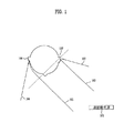
図1は、本発明によるオーディオ信号(audio signal)に対する空間情報(spatialin formation)を人間が認識する方法を示す。マルチチャネルオーディオ信号に対するコーディング方法は、人間がオーディオ信号を3次元的空間として認知するという事実から、複数のパラメータセット(parameter sets)を用いて前記オーディオ信号を3次元的空間情報として表現できるということを利用する。マルチチャネルオーディオ信号の空間情報を表示するための“空間パラメータ(spatial parameter)”には、CLD(Channel level differences)、ICC(Inter Channel Coherences)及びCTD(Channel Time Difference)等がある。CLDは、2チャンネル間のエネルギー差を表し、ICCは、2チャンネル間の相関関係(correlation)を表し、CTDは、2チャンネル間の時間差を表す。 FIG. 1 illustrates a method for a human to recognize spatial information for an audio signal according to the present invention. A coding method for a multi-channel audio signal can represent the audio signal as three-dimensional spatial information using a plurality of parameter sets due to the fact that a human recognizes the audio signal as a three-dimensional space. Is used. “Spatial parameters” for displaying spatial information of a multi-channel audio signal include CLD (Channel level differences), ICC (Inter Channel Channels), CTD (Channel Time Differences), and the like. CLD represents the energy difference between the two channels, ICC represents the correlation between the two channels, and CTD represents the time difference between the two channels.
人間がオーディオ信号をどのように空間的に認識し、空間パラメータの概念がどのように生成されるかについて、図1に示す。遠距離にある音源(sound source)101からの直接的な一つの音波(direct sound wave)103が人間の左耳107に到達し、他の直接的な音波102は頭の周囲で回折(diffract)して右耳106に到達する。これらの2音波102及び103は、到達時間及びエネルギーレベルでズレがあり、このようなズレによってCTD及びCLDパラメータが生成されるわけである。また、もし反射された音波104及び105が両耳に到達する、または、音源101が分散されていると、互いに相関関係を持たない音波が両耳に到達し、これによってICCパラメータが生成される。上記のような原理から生成された空間パラメータを用いて、マルチチャネルオーディオ信号をモノまたはステレオ信号として転送した後、再びマルチチャネルとして出力することができる。本発明は、前記空間情報、すなわち、空間パラメータを前記モノまたはステレオオーディオ信号に埋め込んで転送した後、再びマルチチャネルオーディオ信号に再生できる方法を提供する。本発明は、マルチチャネルオーディオ信号に限定されるわけではないが、本明細書では便宜上、マルチチャネルオーディオ信号について述べるものとする。
FIG. 1 shows how humans perceive audio signals spatially and how the concept of spatial parameters is generated. One
図2は、本発明によるエンコーディング装置(encoding apparatus)を示すブロック図である。同図で、まず、本発明によるエンコーディング装置は、マルチチャネルオーディオ信号(multi−channel audio signal)201を受信する。ここで、‘n’は、入力チャンネル(input channel)の数を表す。該マルチチャネルオーディオ信号201は、オーディオ信号生成部(audio singnal generating part)203でダウンミックス信号Lo/Ro(205)になる。該ダウンミックス信号205は、モノ(mono)またはステレオ(stereo)オーディオ信号を含み、また、マルチチャネルオーディオ信号になりうる。本明細書では、便宜上、ステレオオーディオ信号を例に挙げて説明するが、本発明がステレオオーディオ信号に限定されることはない。そして、前記マルチチャネルオーディオ信号の空間情報、すなわち、空間パラメータが付加情報生成部(side information generating part)204で前記マルチチャネルオーディオ信号201から生成される。本発明で空間情報(spatial information)とは、マルチチャネル(例えば、左、右、中央、周辺左側、周辺右側等)信号をダウンミックスして生成されたダウンミックス信号205を転送し、該転送されたダウンミックス信号を再びマルチチャネルオーディオ信号にアップミックス(upmix)する時に用いられるオーディオ信号チャンネルに対する情報のことをいう。選択的に、ダウンミックス信号205は、外部から直接提供されるダウンミックス信号、例えば、アーティスティックダウンミックス信号(Artistic down−mix signal)202を用いて生成されても良い。
FIG. 2 is a block diagram illustrating an encoding apparatus according to the present invention. In the figure, first, the encoding apparatus according to the present invention receives a
付加情報生成部204で生成された空間情報は、付加情報エンコーディング部(side information encoding part)206で、転送(transmission)及び保存(storage)のための空間情報ビットストリーム(spatial information bitstream)に符号化(encoding)される過程を経る。該空間情報ビットストリームは、適当に再構成(reshaping)された後、埋め込み部(embedding part)207から転送するオーディオ信号、すなわち、ダウンミックス信号205に直接挿入されるが、この時、“デジタルオーディオ埋め込み技法(Digital Audio Embedded Method)”を用いれば良い。例えば、ダウンミックス信号205が、空間情報を保存し難いストレージ媒体(storage media)(例えば、ステレオコンパクトディスク(stereo CD))に保存される、または、SPDIF(Sony/Philips Digital Interface)のような方式で転送する元(raw)PCMオーディオ信号である場合、AACなどで圧縮符号化(compression encoding)される場合とは違い、前記空間情報を保存できる補助データ領域(Ancillary Data Field)が存在しない。この場合、前記“デジタルオーディオ埋め込み技法”を用いると、前記元PCMオーディオ信号に音質歪み(sound quality distortion)が生じることなく前記空間情報を埋め込むことができ、該空間情報が埋め込まれたオーディオ信号は、一般的なデコーダ側では元信号と区別されない。すなわち、空間情報が埋め込まれている出力信号(output signal)Lo'/Ro'(208)は、一般的なPCMデコーダから見ると入力信号Lo/Ro(205)と同じ信号とみなされる。
Spatial information generated by the additional information generation unit 204 is encoded by a side
上記“デジタルオーディオ埋め込み技法”には、ビット置換符号化方法(Bit Replacement Coding Method)、反響挿入方法(Echo Hiding Method)、帯域拡散通信法(Spread−Spectrum −based Method)などがある。ビット置換符号化方法は、量子化されたオーディオサンプルの下位ビット(lower bit)を変形して所望の情報を挿入する方法で、オーディオ信号において下位ビットの変形(modification)がオーディオ信号の品質にほとんど影響を与えないという特性に基づく方法である。反響挿入方法は、人の耳に聞こえないような小さい大きさの反響(echo)をオーディオ信号に挿入する方法である。帯域拡散通信法は、離散コサイン変換(Discrete Cosine Transform)、離散フーリエ変換(Discrete Fourier Transform)等を用いてオーディオ信号を周波数領域に変換した後に、2進数からなる所望の情報をPN(Pseudo Noise)シーケンス(sequence)に帯域拡散(spread spectrum)し、周波数領域(frequency domain)に変換されたオーディオ信号に添加する方法である。本発明では、上記の埋め込み方法のうち、ビット置換符号化方法について説明するが、本発明がこのビット置換符号化方法に限定されることはない。 Examples of the “digital audio embedding technique” include a bit replacement coding method (Bit Replacement Coding Method), an echo insertion method (Echo Hiding Method), and a spread-band communication method (Spread-Spectrum-based Method). The bit permutation coding method is a method in which lower bits of a quantized audio sample are transformed and desired information is inserted, and the modification of lower bits in an audio signal hardly affects the quality of the audio signal. It is a method based on the property of not affecting. The echo insertion method is a method of inserting a small echo (echo) that cannot be heard by human ears into an audio signal. In the spread band communication method, an audio signal is converted into a frequency domain using a discrete cosine transform, a discrete Fourier transform, or the like, and then desired information including binary numbers is converted into a PN (Pseudo Noise). This is a method of adding to an audio signal that has been spread spectrum into a sequence and converted into a frequency domain. In the present invention, the bit substitution coding method will be described among the above-described embedding methods, but the present invention is not limited to this bit substitution coding method.
図3は、本発明による図2に示す空間的エンコーダーを構成する埋め込み部を示す詳細ブロック図である。上記のビット置換符号化方法によって空間情報をダウンミックス信号成分のうち非知覚的成分に埋め込む時、該空間情報を埋め込み可能な挿入ビット長(insertion bits length)(以下、K値という。)は、下位1ビットのみを使用するのではなく、定められた方法(pre−decided method)によってK(K>0)ビットを使用することができる。このKビットは、ダウンミックス信号の下位ビット値を使用することができるが、下位ビットのみに限定されることはない。ここで、定められた方法とは、例えば、心理音響モデル(Psychoacoustic Model)によるマスキング限界値(Masking Threshold)を求め、該マスキング限界値によって適当なビットを割り当てる(allocating)方法をいう。図示の如く、ダウンミックス信号Lo/Ro(301)は、埋め込み部内のバッファ(buffer)303を経てオーディオ信号エンコーディング部306に転送される。マスキング限界値計算部(masking threshold computing part)304は、入力されたオーディオ信号を一定の区間(section)(例えば、ブロック(block))に分け、該当の区間に対するマスキング限界値を求める。また、マスキング限界値計算部304は、マスキング限界値によって、聴覚的な歪み(aural distortion)が生じることなく変更(modify)可能なダウンミックス信号の挿入ビット長、すなわち、K値を求める。すなわち、前記空間情報を前記ダウンミックス信号に埋め込むのに使用可能なビット数を、ブロック別に割り当てる。本明細書で、ブロックとは、フレーム(frame)内に存在する一つの挿入ビット長(すなわち、K値)を用いて挿入されたデータ単位のことをいう。一つのフレームには、1個以上のブロックが存在でき、したがって、フレーム長が固定されていると、ブロック長は、ブロックの個数が増加するにつれて減少する。前記K値が決定されると、該K値を空間情報ビットストリームに含めることができる。すなわち、ビットストリーム再構成部(bitstream reshaping part)305は、前記K値を含むように前記空間情報ビットストリームを再構成できる。この場合、前記空間情報ビットストリームにはシンクワード(syncword)、誤り検出コード(error detection code)または誤り訂正コード(error correction code)などを含めることができる。
FIG. 3 is a detailed block diagram showing an embedding unit constituting the spatial encoder shown in FIG. 2 according to the present invention. When spatial information is embedded in a non-perceptual component of the downmix signal component by the above bit permutation encoding method, an insertion bit length (hereinafter referred to as a K value) in which the spatial information can be embedded is as follows. Rather than using only the lower 1 bit, K (K> 0) bits can be used according to a pre-decided method. The K bit can use the lower bit value of the downmix signal, but is not limited to only the lower bit. Here, the determined method refers to, for example, a method of obtaining a masking threshold value (Masking Threshold) using a psychoacoustic model and assigning appropriate bits according to the masking threshold value. As illustrated, the downmix signal Lo / Ro (301) is transferred to the audio
再構成された空間情報ビットストリームは、埋め込み可能な形態に再整列(rearrange)されることができる。再整列された前記空間情報ビットストリームは、オーディオ信号エンコーディング部306で前記ダウンミックス信号に埋め込まれ、前記空間情報ビットストリームが埋め込まれたオーディオ信号Lo’/Ro’(307)として出力される。このとき、前記空間情報ビットストリームは、前記ダウンミックス信号のKビット内に埋め込み可能である。前記K値は、ブロック内で固定された一つの値を持つことができる。いずれの場合においても、前記K値は前記空間情報ビットストリームの再構成過程または再整列過程で空間情報ビットストリームに挿入されて、デコーディング装置に転送され、デコーディング装置は、前記K値を用いて空間情報データを復元することができる。
The reconstructed spatial information bitstream can be rearranged into an embeddable form. The rearranged spatial information bit stream is embedded in the downmix signal by an audio
前述の如く、前記空間情報ビットストリームは、ブロック別に前記ダウンミックス信号に埋め込まれる過程を経る。この過程には、様々な方法が用いられることができる。第1の方法は、単純に前記ダウンミックス信号の下位Kビットのみを0に入れ替えた(substitude)後、再整列(rearrange)された前記空間情報ビットストリームデータを加える方法である。例えば、K値が3で、ダウンミックス信号のあるサンプルデータが11101101で、埋め込むべき空間情報ビットストリームデータが111である場合、前記11101101の下位3ビットを0に入れ替えて11101000にした後、前記空間情報ビットストリームデータ111を加えて11101111にする。 As described above, the spatial information bit stream is embedded in the downmix signal block by block. Various methods can be used for this process. The first method is a method of adding the rearranged spatial information bitstream data after simply substituting only the lower K bits of the downmix signal with 0. For example, when the K value is 3, the sample data with the downmix signal is 11101101, and the spatial information bitstream data to be embedded is 111, the lower 3 bits of the 11101101 are replaced with 0 to 11101000, and then the space The information bit stream data 111 is added to make 11101111.
第2の方法は、ディザリング(dithering)方法を利用するもので、まず、再整列された空間情報ビットストリームデータを前記ダウンミックス信号の挿入領域から引いた後に、前記ダウンミックス信号を前記K値に基づいて再量子化し、再量子化された前記ダウンミックス信号に、前記再整列された空間情報ビットストリームデータを加える方法である。例えば、K値が3で、ダウンミックス信号のあるサンプルデータが11101101で、埋め込むべき空間情報ビットストリームデータが111である場合、前記11101101から111を引いて11100110にした後、下位3ビットに対して再量子化を行って11101000(四捨五入を適用)にし、次に、11101000に111を加えて11101111にする。 The second method uses a dithering method. First, after subtracting the rearranged spatial information bitstream data from the insertion region of the downmix signal, the downmix signal is converted to the K value. The re-ordered spatial information bitstream data is added to the down-mixed signal that has been re-quantized based on the re-quantization. For example, if the K value is 3, the sample data with the downmix signal is 11101101, and the spatial information bitstream data to be embedded is 111, after subtracting 111 from 11101101 to 11100110, the lower 3 bits Re-quantization is performed to make 11101000 (rounding is applied), and 111 is added to 11101000 to make 11101111.
前記ダウンミックス信号に埋め込まれる空間情報ビットストリームは任意のビットストリームであるがために白色雑音的な特性を持たないことがある。ダウンミックス信号に白色雑音形態の信号が加えられることが、音質特性の上で有利なため、前記空間情報ビットストリームを白色化(whitening)する過程を行なってから前記ダウンミックス信号に加えると良い。前記白色化は、シンクワード以外の空間情報ビットストリームに適用できる。本発明で白色化とは、オーディオ信号の音量が全ての周波数領域で同一であるか、略同一な大きさを持つランダム信号にすることをいう。また、空間情報ビットストリームをダウンミックス信号に埋め込む過程で、前記空間情報ビットストリームにノイズシェーピング(Noise shaping)技法を適用して聴覚的歪みを最小化することができる。本発明でノイズシェーピングとは、量子化過程で生成される量子化ノイズのエネルギーが可聴周波数帯域以上の高周波数帯域へ移動するようにノイズ特性を変形させる、または、該当のオーディオ信号からマスキング限界値を求め、該マスキング限界値に対応する時変(time−varing)フィルタを生成し、該フィルタによって量子化過程で発生するノイズの特性を変形させる過程のことをいう。 Since the spatial information bit stream embedded in the downmix signal is an arbitrary bit stream, it may not have white noise characteristics. Since it is advantageous in terms of sound quality characteristics to add a white noise signal to the downmix signal, it may be added to the downmix signal after whitening the spatial information bitstream. The whitening can be applied to a spatial information bit stream other than a sync word. In the present invention, whitening means that the volume of the audio signal is the same in all frequency regions or is a random signal having substantially the same magnitude. In addition, in the process of embedding the spatial information bitstream in the downmix signal, a noise shaping technique can be applied to the spatial information bitstream to minimize auditory distortion. In the present invention, noise shaping means that noise characteristics are modified so that the energy of quantization noise generated in the quantization process moves to a higher frequency band higher than the audible frequency band, or the masking limit value from the corresponding audio signal. A time-varing filter corresponding to the masking limit value is generated, and a characteristic of noise generated in the quantization process is deformed by the filter.
図4は、本発明による空間情報ビットストリームを再整列する第1の方法を示す。図4を参照すると、上述のように、前記空間情報ビットストリームは、前記K値を用いて埋め込まれることができる形態に再整列できる。このとき、前記空間情報ビットストリームは様々な方式で再整列されて、前記ダウンミックス信号に埋め込まれることができるが、図4は、上記の方式のうち、サンプルプレーン順に前記空間情報を埋め込む方式を示す。該第1の方法は、Kビット単位に該当のブロックに対する前記空間情報ビットストリームを分散し、分散した前記空間情報ビットストリームを順次埋め込むことができるように前記空間情報ビットストリームを再整列する方法である。K値が4で、1つのブロック405がN個のサンプル403で構成された場合、空間情報ビットストリーム401は、各サンプルの下位4ビットに順次埋め込まれることができるように再整列できる。前述の如く、本発明は、各サンプルの下位4ビットに空間情報ビットストリームを埋め込む場合に限定されることはない。そして、各サンプルの下位Kビット内では、図示の如く、前記空間情報ビットストリームが最上位ビットから埋め込まれる(MSB(Most Significant Bit) first)、または、最下位ビットから埋め込まれる(LSB(Least Significant Bit) first))。
FIG. 4 shows a first method of reordering the spatial information bitstream according to the present invention. Referring to FIG. 4, as described above, the spatial information bitstream can be rearranged into a form that can be embedded using the K value. At this time, the spatial information bitstream can be rearranged by various methods and embedded in the downmix signal. FIG. 4 illustrates a method of embedding the spatial information in the order of sample planes. Show. The first method is a method of distributing the spatial information bitstream for a corresponding block in K bit units and rearranging the spatial information bitstream so that the distributed spatial information bitstream can be embedded sequentially. is there. If the K value is 4 and one block 405 is composed of
図4で、矢印404は埋め込まれる方向を表し、括弧中の数字はデータ再整列順序を表す。また、ビットプレーンは、複数のビットで構成される一定のビット階層をいう。前記空間情報ビットストリームが埋め込まれる挿入領域で、埋め込み可能なビット数よりも埋め込むべき空間情報ビットストリームのビット数が小さい場合には、残りのビットを0で埋める(406)、残りのビットにランダム信号(Random signal)を入れる、または、元のダウンミックス信号に置換することができる。例えば、ブロックを構成するサンプル数(N)が100で、K値が4である場合、前記ブロックに埋め込み可能なビット数(W)は、W=N*K=100*4=400ビットとなる。もし埋め込むべき空間情報ビットストリームのビット数(V)が390ビットである場合(すなわち、V<Wである場合)、残りの10ビットは0で埋めるか、ランダム信号を入れるか、元のダウンミックス信号に置き換えるか、データの終わりを知らせるテールビット列(tail sequence)で埋めるか、または、これらを組みわせて埋めれば良い。前記テールビット列は、該当のブロックで空間情報ビットストリームの終わりを知らせるビット列を意味する。図4ではブロック毎に残りのビットを埋めているが、本発明は、上記のような方法で、挿入フレーム毎に残りのビットを埋める場合も含む。
In FIG. 4, an
図5は、本発明による空間情報ビットストリームを再整列する第2の方法を示す。図5を参照すると、該第2の方法は、空間情報ビットストリーム501をビットプレーン(Bit Plane)502の順に再整列する。この場合、前記空間情報ビットストリームは、ブロック毎に前記ダウンミックス信号の下位ビットから順次埋め込まれることができるが、本発明はこれに限定されない。例えば、ブロックを構成するサンプル数(N)が100で、K値が4である場合、まず、ビットプレーン0(502)を構成する最下位100ビットをまず埋め、続いてビットプレーン1(502)を構成する100ビットを埋める。
FIG. 5 shows a second method for reordering the spatial information bitstream according to the invention. Referring to FIG. 5, the second method rearranges the spatial information bitstream 501 in the order of the
図5で、矢印505は、埋め込まれる方向を表し、括弧中の数字は、データ再整列順序を表す。この第2の方法は、特に、任意の位置でシンクワード(Sync Word)を抽出するのに有利である。上記のようにして再整列及び符号化された信号から、挿入された空間情報ビットストリームのシンクワードを探すときには、LSBのみを抽出してシンクワードを検索すれば良い。また、この第2の方法は、埋め込むべき空間情報ビットストリームのビット数(V)によって、最小のLSBのみを使用する効果が期待できる。このときにも、前記空間情報ビットストリームが埋め込まれる挿入領域で、埋め込み可能なビット数(W)よりも埋め込むべき空間情報ビットストリームのビット数(V)が小さい場合には、上記のように残りのビットを0で埋めるか(506)、残りのビットにランダム信号を入れるか、残りのビットを元のダウンミックス信号に変えるか、残りのビットをデータの終わりを知らせるテールビット列で埋めるか、または、これらを組み合わせて埋めれば良い。特に、上記方法のうち、前記ダウンミックス信号をそのまま利用することが有利である。図5は、ブロック毎に残りのビットを埋める例を示しているが、本発明は上記のような方法で挿入フレーム毎に残りのビットを埋める場合を含む。
In FIG. 5, an
図6Aは、本発明による、ダウンミックス信号に空間情報ビットストリームを埋め込むためのビットストリーム構造を示す。図6を参照すると、空間情報ビットストリーム607は、ビットストリーム再構成部305で、該空間情報ビットストリームに対するシンクワード(Sync Word)603とK値604を含むように再構成できる。また、再構成過程で、空間情報ビットストリーム607が転送または保存の際に損傷したか否かを判断できる少なくとも一つの誤り検出コードまたは誤り訂正コード606,608(以下、誤り検出コードと略す。)を、前記再構成された空間情報ビットストリームに含めることができる。該誤り検出コードは、CRC(Cyclic Redundancy Check)を含む。前記誤り検出コードは、2段階に分けて含めることができるが、K値が含まれたヘッダ601に対する誤り検出コード1と、空間情報ビットストリームのフレームデータ602に対する誤り検出コード2を、前記空間情報ビットストリームに個別に含めることができる。さらに、その他情報605が個別に、前記埋め込みのための空間情報ビットストリームに含めることができる。このその他情報605には、空間情報ビットストリームの再整列方法に関する情報などを含めることができる。
FIG. 6A illustrates a bitstream structure for embedding a spatial information bitstream in a downmix signal according to the present invention. Referring to FIG. 6, the
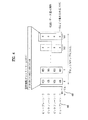
図6Bは、図6Aの空間情報ビットストリームを示す詳細図である。図示のように、図6Bは、空間情報ビットストリーム610の1フレームが2個のブロックで構成された実施例を示しているが、本発明はこの実施例に限定されない。図6Bを参照すると図6Bの空間情報ビットストリームも、シンクワード612、K値(K1,K2,K3及びK4)613、614、615及び616、その他情報617、誤り検出コード618及び623を含んでなることができる。空間情報ビットストリーム610は、2ブロックで構成されているが、ステレオ信号の場合、ブロック1は左(left)チャンネルと右(Right)チャンネルに対するブロック619及び620でそれぞれ構成され、ブロック2も、左チャンネルと右チャンネルに対するブロック621及び622でそれぞれ構成されることができる。図6Bは、ステレオ信号について示しているが、本発明がこのステレオ信号に限定されることはない。これらのブロックに対する挿入ビット長(K値)は、ヘッダ部分に含まれる。K1613は、ブロック1の左チャンネルに対する挿入ビット長、K2614はブロック1の右チャンネルに対する挿入ビット長、K3615はブロック2の左チャンネルに対する挿入ビット長、K4616はブロック2の右チャンネルに対する挿入ビット長を示す。また、前記誤り検出コードは2段階に分けて含めることができるが、K値の含まれたヘッダ609に対する誤り検出コード1(618)と、前記空間情報ビットストリームのフレームデータ611に対する誤り検出コード2(623)を別個に含めることができる。
FIG. 6B is a detailed diagram illustrating the spatial information bitstream of FIG. 6A. As shown in the figure, FIG. 6B shows an embodiment in which one frame of the spatial information bitstream 610 is composed of two blocks, but the present invention is not limited to this embodiment. Referring to FIG. 6B, the spatial information bit stream of FIG. 6B also includes a
図7は、本発明によるデコーディング装置を示すブロック図である。同図に示すように、本発明によるデコーディング装置は、空間情報ビットストリームの埋め込まれたオーディオ信号Lo’/Ro’(701)を受信する。該空間情報ビットストリームが埋め込まれたオーディオ信号は、モノ、ステレオ、またはマルチチャネル信号になり得、便宜上、ここではステレオ信号に基づいて説明するが、本発明はこれに限定されない。なお、埋め込み信号デコーディング部702は、オーディオ信号701から空間情報ビットストリームを抽出できる。埋め込み信号デコーディング部702で抽出された空間情報ビットストリームは、符号化された空間情報ビットストリームであり、該符号化された空間情報ビットストリームは、空間情報デコーディング部703への入力信号になりうる。空間情報デコーディング部703は、前記符号化された空間情報ビットストリームを復号化してマルチチャネル生成部704に出力する。マルチチャネル生成部704は、ダウンミックス信号701及び復号化より得られた空間情報を入力として受信し、マルチチャネルオーディオ信号705として出力する。
FIG. 7 is a block diagram illustrating a decoding apparatus according to the present invention. As shown in the figure, the decoding apparatus according to the present invention receives an audio signal Lo '/ Ro' (701) in which a spatial information bitstream is embedded. The audio signal in which the spatial information bit stream is embedded may be a mono, stereo, or multi-channel signal. For convenience, the audio signal is described here based on the stereo signal, but the present invention is not limited thereto. The embedded
図8は、本発明によるデコーディング装置を構成する埋め込み信号デコーディング部702の詳細を示す。図8を参照すると、この埋め込み信号デコーディング部702には、空間情報の埋め込まれたオーディオ信号Lo’/Ro'が入力され、シンクワード探索部802は、該オーディオ信号801からシンクワード(Sync Word)を検出する。この場合、該シンクワードは、前記オーディオ信号の一チャンネルから検出することができる。該シンクワードが検出された後に、ヘッダデコーディング部803は、ヘッダ領域をデコーディングする。このとき、該ヘッダ領域からあらかじめ指定された大きさの情報を読み出し、データ逆変形部804は、読み出された情報のうち、シンクワード以外のヘッダ領域情報に逆白色化技法を適用することができる。次に、この逆白色化技法の適用されたヘッダ領域情報から前記ヘッダ領域の大きさ情報などを得ることができる。また、データ逆変形部804は、残りの空間情報ビットストリームに対しても逆白色化技法を適用できる。このヘッダデコーディングによってK値などの情報を得、K値などの該情報を用いて、再整列された空間情報ビットストリームを再び整列することによって本来の空間情報ビットストリーム805を得ることができる。また、ダウンミックス信号と空間情報ビットストリームのフレームを整列するためのシンク位置(Sync Position)情報、すなわち、フレーム整列情報806を得ることができる。
FIG. 8 shows details of the embedded
図9は、本発明によるオーディオ信号を一般のPCMデコーディング装置で再生する様子を示す。図9を参照すると、空間情報ビットストリームの埋め込まれたオーディオ信号Lo’/Ro’が、一般のPCMデコーディング装置の入力として印加される。この場合、一般のPCMデコーディング装置は、前記空間情報ビットストリームの埋め込まれたオーディオ信号Lo’/Ro’を、正常なステレオオーディオ信号と認識して音声を再生する。該再生された音声は、音質の点では、空間情報の埋め込まれる前のオーディオ信号902と区別されない。したがって、本発明による空間情報が埋め込まれたオーディオ信号は、一般のPCMデコーディング装置において正常なステレオ信号を再生する互換性を有し、マルチチャネルに復号化可能なデコーダでマルチチャネルオーディオ信号を提供できる長所を有する。
FIG. 9 shows a state in which an audio signal according to the present invention is reproduced by a general PCM decoding apparatus. Referring to FIG. 9, an audio signal Lo '/ Ro' embedded with a spatial information bit stream is applied as an input of a general PCM decoding apparatus. In this case, a general PCM decoding apparatus recognizes the audio signal Lo ′ / Ro ′ in which the spatial information bitstream is embedded as a normal stereo audio signal and reproduces sound. The reproduced sound is not distinguished from the
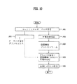
図10は、本発明によるダウンミックス信号に空間情報を埋め込むエンコーディング方法を示すフローチャートである。図10を参照すると、マルチチャネルオーディオ信号(1001)からオーディオ信号をダウンミックス(1002)する。この場合、このダウンミックス信号は、モノ、ステレオまたはマルチチャネル信号のうちの1つとすることができる。次に、マルチチャネルオーディオ信号から空間情報を抽出(1003)し、該空間情報を用いて空間情報ビットストリームを生成(1004)する。前記空間情報ビットストリームを前記ダウンミックス信号に埋め込み(1005)、前記空間情報ビットストリームの埋め込まれたダウンミックス信号を含む全体ビットストリームをデコーディング装置に転送(1006)する。ここで、本発明は、前記ダウンミックス信号を用いて、前記空間情報ビットストリームが埋め込まれる挿入領域の挿入ビット長(すなわち、K値)を求め、前記挿入領域に空間情報ビットストリームを埋め込むことができる。 FIG. 10 is a flowchart illustrating an encoding method for embedding spatial information in a downmix signal according to the present invention. Referring to FIG. 10, an audio signal is downmixed (1002) from a multi-channel audio signal (1001). In this case, the downmix signal can be one of a mono, stereo or multi-channel signal. Next, spatial information is extracted from the multi-channel audio signal (1003), and a spatial information bit stream is generated (1004) using the spatial information. The spatial information bitstream is embedded in the downmix signal (1005), and the entire bitstream including the downmix signal in which the spatial information bitstream is embedded is transferred to a decoding device (1006). Here, the present invention obtains an insertion bit length (that is, a K value) of an insertion area in which the spatial information bitstream is embedded using the downmix signal, and embeds the spatial information bitstream in the insertion area. it can.
図11は、本発明によるダウンミックス信号に埋め込まれた空間情報をデコーディングする方法を示すフローチャートである。図11を参照すると、デコーディング装置は、空間情報ビットストリームが埋め込まれたダウンミックス信号を含む全体ビットストリームを受信(1101)し、該ビットストリームからダウンミックス信号を検出(1102)する。また、前記デコーディング装置は前記全体ビットストリームから空間情報ビットストリームを検出及びデコーディング(1103)する。前記デコーディング装置は、このデコーディングによって空間情報を抽出(1104)し、抽出された空間情報を用いてダウンミックス信号をデコーディング(1105)する。この場合、前記ダウンミックス信号は、2チャンネルにデコーディングするか、または、マルチチャネルにデコーディングすることができる。ここで、本発明は、前記空間情報ビットストリームの埋め込み方法に関する情報及びK値に関する情報を読み出し、該読み出された埋め込み方法及びK値を用いて前記空間情報ビットストリームをデコーディングすることができる。 FIG. 11 is a flowchart illustrating a method for decoding spatial information embedded in a downmix signal according to the present invention. Referring to FIG. 11, the decoding apparatus receives (1101) an entire bitstream including a downmix signal in which a spatial information bitstream is embedded, and detects a downmix signal from the bitstream (1102). Also, the decoding apparatus detects and decodes (1103) a spatial information bit stream from the entire bit stream. The decoding apparatus extracts spatial information by this decoding (1104), and decodes the downmix signal using the extracted spatial information (1105). In this case, the downmix signal can be decoded into two channels or multi-channel. Here, the present invention can read information on the embedding method of the spatial information bitstream and information on the K value, and can decode the spatial information bitstream using the read embedding method and K value. .
図12は、本発明によるダウンミックス信号に埋め込まれる空間情報ビットストリームのフレーム長を示す。図12を参照して、本発明で“フレーム”とは、一つのヘッダを持つ一定の長さの独立した復号化が可能な単位のことをいい、本明細書では、“フレーム”が、後続する“挿入フレーム”を意味する。本発明で“挿入フレーム”とは、ダウンミックス信号に空間情報ビットストリームを埋め込む単位のことをいう。この挿入フレーム長は、フレーム毎に定義されるか、または、あらかじめ指定された長さを使用することができる。例えば、前記挿入フレーム長は、空間情報を復号化して適用する単位に該当する空間情報ビットストリームのフレーム長(S)(以下、“復号化フレーム長”と略す。)と同一の長さを持つようにするか(図12の(a)参照)、Sの倍数になるようにするか(図12の(b)参照)、または、SがNの倍数になるようにする(図12の(c)参照)方法がある。図12の(a)に示すように、N=Sの場合には、復号化フレーム長(S)1201と前記挿入フレーム長(N)1202が一致するので、復号化過程が容易になる。図12の(b)に示すように、N>Sの場合では、複数の復号化フレーム1203を纏めて一つの挿入フレーム(N)1204として転送し、これにより、ヘッダや誤り検出コード(例えば、CRC)などによって付加されるビット数を低減することができる。図12の(c)に示すように、N<Sの場合では、数個の挿入フレーム(N)1206を纏めて一つの復号化フレーム長(S)1205にすることができる。前記挿入フレームヘッダ内には、空間情報が埋め込まれる挿入ビット長に関する情報、前記挿入フレーム長(N)に関する情報、または、前記挿入フレーム内に含まれるサブフレーム個数に関する情報などが情報として挿入されることができる。
FIG. 12 shows the frame length of the spatial information bit stream embedded in the downmix signal according to the present invention. Referring to FIG. 12, in the present invention, a “frame” refers to a unit having a certain header and capable of independent decoding of a certain length, and in this specification, “frame” is a succeeding unit. Means “insert frame”. In the present invention, an “insert frame” refers to a unit in which a spatial information bit stream is embedded in a downmix signal. This insertion frame length is defined for each frame, or a predesignated length can be used. For example, the insertion frame length has the same length as the frame length (S) of the spatial information bit stream corresponding to the unit to be applied after decoding the spatial information (hereinafter abbreviated as “decoded frame length”). 12 (see (a) of FIG. 12), a multiple of S (see (b) of FIG. 12), or S is a multiple of N (see (12) of FIG. 12). c) see) there is a method. As shown in FIG. 12A, when N = S, the decoding frame length (S) 1201 and the insertion frame length (N) 1202 match, so that the decoding process is facilitated. As shown in FIG. 12B, in the case of N> S, a plurality of decoded
図13は、本発明によるダウンミックス信号に挿入フレーム単位で埋め込まれる空間情報ビットストリームを示す。まず第1に、図12の(a)、(b)及び(c)に示す場合はいずれも、前記挿入フレームと前記復号化フレームが互いに整数倍になるように構成される。図13を参照すると、固定された長さのビットストリーム、例えば、トランスポートストリーム(Transport Stream:TS)1303のようなフォーマットのパケット(packet)を構成して転送しても良い。特に、空間情報ビットストリームの復号化フレームの長さによらず、前記空間情報ビットストリーム1301を一定長のパケット単位に纏め、該パケットにTSヘッダ1302などの情報を入れて転送することができる。前記挿入フレーム長は、フレーム毎に定義されても良く、フレーム内で定義せずにあらかじめ指定された長さを使用しても良い。
FIG. 13 shows a spatial information bit stream embedded in a downmix signal according to the present invention in units of inserted frames. First, in each of the cases shown in FIGS. 12A, 12B, and 12C, the inserted frame and the decoded frame are configured to be an integral multiple of each other. Referring to FIG. 13, a bit stream having a fixed length, for example, a packet having a format such as a transport stream (TS) 1303 may be configured and transferred. In particular, regardless of the length of the decoding frame of the spatial information bit stream, the spatial
この方法は、ダウンミックス信号の特性によって、ブロック毎にマスキング限界値が異なり、これにより、前記ダウンミックス信号の音質劣化無しに割り当てうる最大ビット数(K_max)が異なってくる点から、空間情報ビットストリームのデータ転送速度を可変させるために必要である。例えば、前記K_maxが該当のブロックで必要とする空間情報ビットストリームを全て表現するに不足している場合には、K_maxまでデータを転送し、残りは以降の他のブロックで転送すれば良い。K_maxで十分な場合には、次のブロックに対する空間情報ビットストリームをあらかじめ取り込める。この場合、各TSパケットは独立したヘッダを持ち、該ヘッダ内には、シンクワード(Sync Word)、TSパケット長情報、TSパケット内に含まれるサブフレーム数情報またはパケット内で割り当てられた挿入ビット長情報などを含めることができる。 In this method, the masking limit value is different for each block depending on the characteristics of the downmix signal, and the maximum number of bits (K_max) that can be assigned without deterioration of the sound quality of the downmix signal varies accordingly. This is necessary to vary the data transfer rate of the stream. For example, if K_max is insufficient to express all the spatial information bitstreams required by the corresponding block, data may be transferred up to K_max, and the rest may be transferred in other blocks thereafter. If K_max is sufficient, a spatial information bitstream for the next block can be captured in advance. In this case, each TS packet has an independent header, and in the header, a sync word, TS packet length information, information on the number of subframes included in the TS packet, or an insertion bit assigned in the packet Long information can be included.
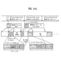
図14Aは、挿入フレーム単位に埋め込まれる空間情報ビットストリームの時間軸整列(time align)問題を解決するための第1の方法を示す。前記挿入フレームの長さはフレーム毎に定義されるか、または、あらかじめ指定された長さを使用することができる。前記挿入フレーム単位に埋め込む方法は、埋め込まれた空間情報ビットストリームの挿入フレーム開始位置とダウンミックス信号との時間軸整列(time align)が合わないという問題がありうる。したがって、この時間軸整列の問題を解決する方法が必要である。図14Aに示す第1の方法は、空間情報の復号化フレーム1403に対するヘッダ1402(以下、“復号化フレームヘッダ”という。)を別個に置く方法である。復号化フレームヘッダ1402内には、前記空間情報が適用されるオーディオ信号の位置情報が存在しているか否かに関する識別情報を含めることができる。
FIG. 14A illustrates a first method for solving the time alignment problem of a spatial information bitstream embedded in an inserted frame unit. The length of the insertion frame may be defined for each frame, or a predetermined length may be used. The method of embedding in the inserted frame unit may have a problem that the time axis alignment between the inserted frame start position of the embedded spatial information bitstream and the downmix signal does not match. Therefore, there is a need for a method that solves this time axis alignment problem. The first method shown in FIG. 14A is a method of separately placing a header 1402 (hereinafter referred to as “decoded frame header”) for a decoded
TSパケット1404及び1405について説明すると、TSパケットヘッダ1404内には、現在のパケット内に復号化フレームヘッダ1402の存在の有無を知らせる識別情報1408(例えば、フラグ)を含めることができる。
The
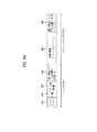
もし識別情報1408が1であれば(すなわち、復号化フレームヘッダ1402が存在すれば)、該復号化フレームヘッダから、前記空間情報ビットストリームが適用されるダウンミックス信号の位置情報が存在しているか否かに関する識別情報を読み出すことができる。次に、該読み出された識別情報によって、前記復号化フレームヘッダ1402から、前記空間情報ビットストリームが整列されるべきダウンミックス信号に対する位置情報1409(例えば、遅延(delay)情報)を読み出すことができる。もし、識別情報1411が0であれば、TSパケットのヘッダ内に前記位置情報を含めない。一般に、空間情報ビットストリーム1403は、対応するダウンミックス信号1401よりも先に来ることが好ましいので、位置情報1409は、主として遅延(delay)に対するサンプル値でありうる。一方、遅延が過大なため、サンプル値を表現するのに必要な情報量が過大になる問題を防止すべく、サンプル単位ではなく、一定サンプルを纏めて表現するサンプル群単位(例えば、グラニュール(granule)単位)などを定義し、該サンプル群単位に前記位置情報を表現しても良い。前述したように、前記TSヘッダ内には、TSシンクワード1406、挿入ビット長1407、前記復号化フレームヘッダの存在の有無に関する識別情報及びその他情報1409を含めることができる。
If the identification information 1408 is 1 (that is, if the decoded frame header 1402 exists), the position information of the downmix signal to which the spatial information bitstream is applied exists from the decoded frame header. Identification information regarding whether or not can be read. Next, position information 1409 (eg, delay information) for the downmix signal in which the spatial information bitstream is to be aligned is read from the decoded frame header 1402 according to the read identification information. it can. If the identification information 1411 is 0, the position information is not included in the header of the TS packet. In general, since the
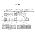
図14bは、フレーム毎に定義された長さの挿入フレームに埋め込まれる空間情報ビットストリームの時間軸整列(time align)問題を解決するための第2の方法を示す。TSパケットで構成される場合について説明すると、第2の方法は、復号化フレームの始点1413、TSパケットの始点、及び対応するダウンミックス信号1412の始点を一致させる方法である。このように一致する部分に対して、上記3つの始点が整列されたことを知らせる識別情報1420または1422(例えば、フラグ)を、前記TSパケットのヘッダ1415内に含めることができる。図14Bでは、ダウンミックス信号のn番目のフレーム1412で上記3つの識別情報が一致している。この場合、識別情報1422は1の値を持つ。もし上記3つの識別情報が一致しないと、識別情報1420は0の値を持つことができる。これら3つの始点を一致させるために、以前のTSパケットに続く一定部分1417(fill部分)は、0で埋められるか、ランダム信号を入れるか、元来のダウンミックスされたオーディオ信号に変えるか、または、これらを組み合わせて埋めることができる。前述したように、TSヘッダ1415内には、TSシンクワード1418、挿入ビット値1419及びその他情報1421を含めることができる。
FIG. 14b shows a second method for solving the time alignment problem of a spatial information bitstream embedded in an insertion frame having a defined length for each frame. The case where the packet is composed of TS packets will be described. The second method is a method of matching the start point 1413 of the decoded frame, the start point of the TS packet, and the start point of the corresponding downmix signal 1412. Identification information 1420 or 1422 (for example, a flag) notifying that the three start points are aligned with respect to the matching part can be included in the header 1415 of the TS packet. In FIG. 14B, the three pieces of identification information coincide with each other in the nth frame 1412 of the downmix signal. In this case, the identification information 1422 has a value of 1. If the three pieces of identification information do not match, the identification information 1420 can have a value of zero. To match these three starting points, the constant part 1417 (fill part) following the previous TS packet is padded with zeros, puts a random signal, or changes to the original downmixed audio signal, Or, a combination of these can be filled. As described above, the TS header 1415 can include a
図15は、本発明によるダウンミックス信号に空間情報ビットストリームがアタッチ(attach)されるように生成する方法を示す。前記空間情報ビットストリームがアタッチされるフレーム(以下、“結合フレーム”という。)の長さは、フレーム毎に定義された長さ単位である、または、フレーム毎に定義されるのではなくあらかじめ指定された一定の長さ単位でありうる。例えば、前記挿入フレーム長は、図示のように、前記空間情報の復号化フレーム1504の長さと互いに整数倍になる、または、固定された長さ単位とすることができる。もし、復号化フレーム長1504と前記挿入フレーム長が異なるときは、前記空間情報ビットストリームを任意に切って前記挿入フレームに埋め合わせるのではなく、前記空間情報ビットストリームを分離せずに、例えば、復号化フレーム1504と同じ長さ単位に前記挿入フレームを生成すれば良い。このとき、前記空間情報ビットストリームはダウンミックス信号に埋め込まれるように構成することができ、また、前記ダウンミックス信号に埋め込まれずに前記ダウンミックス信号にアタッチされるように構成することができる。PCM信号のようにアナログ信号をデジタル信号に変換した信号(以下、“第1のオーディオ信号”という。)では、前記空間情報ビットストリームが前記第1のオーディオ信号に埋め込まれるように構成することができる。MP3のようにより圧縮されたデジタル信号(以下、“第2のオーディオ信号”という。)では、前記空間情報ビットストリームが前記第2のオーディオ信号にアタッチされるように構成することができる。前記第2のオーディオ信号に対する、例えば前記ダウンミックス信号も、圧縮された形態のビットストリームで表現することができる。したがって、図示のように、圧縮された形態のダウンミックス信号ビットストリーム1502が存在し、このダウンミックス信号ビットストリーム1502に、空間情報に対する復号化フレーム1504長でアタッチすることができる。したがって、本発明では、前記空間情報ビットストリームを一度に集中的(burst)に転送することができる。前記復号化フレームにはヘッダ1503が存在でき、前記ヘッダ1503には、空間情報が適用されるダウンミックス信号の位置情報を含めることができる。
FIG. 15 illustrates a method for generating a spatial information bitstream to be attached to a downmix signal according to the present invention. The length of the frame to which the spatial information bitstream is attached (hereinafter referred to as “combined frame”) is a length unit defined for each frame, or is specified in advance instead of being defined for each frame. Can be a certain unit of length. For example, the inserted frame length may be an integral multiple of the length of the spatial
また、本発明では、前記空間情報ビットストリームを圧縮された形態の結合フレーム(例えば、TSビットストリーム1506)にし、前記圧縮された形態のダウンミックス信号ビットストリーム1502にアタッチすることができる。この場合、TSビットストリーム1506に対するTSヘッダ1505が存在できる。前記結合フレームのヘッダ(すなわち、TSヘッダ1505)には、結合フレームシンク情報1507、前記結合フレーム内に復号化フレームのヘッダが存在するか否かに関する識別情報1508、前記結合フレームに含まれるサブフレーム数情報またはその他情報1509のうち一つ以上を含めることができる。また、前記結合フレーム内には、前記結合フレームの始点及び前記復号化フレームの始点が一致しているか否かに関する識別情報を含めることができる。もし前記結合フレーム内に前記復号化フレームヘッダが存在すると、前記復号化フレームヘッダから、前記空間情報が適用されるダウンミックス信号の位置情報が存在しているか否かに関する識別情報を読み出す。次に、前記識別情報によって、前記空間情報が適用されるダウンミックス信号の位置情報を読み出すことができる。
In the present invention, the spatial information bit stream can be converted into a combined frame (for example, a TS bit stream 1506) in a compressed form, and can be attached to the down-mix signal bit stream 1502 in the compressed form. In this case, a
図16は、本発明によるダウンミックス信号に様々な大きさの挿入フレームで埋め込まれる空間情報ビットストリームをエンコーディングする方法を示すフローチャートである。まず、マルチチャネルオーディオ信号(1601)からオーディオ信号をダウンミックス(1602)する。該ダウンミックス信号はモノまたはステレオ信号を含むことができる。また、マルチチャネルオーディオ信号(1601)から空間情報を抽出(1603)し、該空間情報を用いて空間情報ビットストリームを生成(1604)する。生成された空間情報ビットストリームはフレーム毎に、復号化フレームと互いに整数倍に該当する長さの挿入フレーム単位に前記ダウンミックス信号に埋め込むことができる。もし、復号化フレーム長(S)が挿入フレーム長(N)よりも大きいと(1605)、前記挿入フレーム長(N)は、複数のNを纏めて一つのSと同一になるように形成(1607)する。もし復号化フレーム長(S)が、挿入フレーム長(N)よりも小さいと(1606)、前記挿入フレーム長(N)を、複数のSを纏めて一つのNと同一になるように形成(1608)する。もしNとSが同一であれば、前記挿入フレーム長(N)を、復号化フレーム長(S)と同一に形成(1609)する。このような方式で形成された空間情報ビットストリームは、前記ダウンミックス信号に埋め込まれ(1610)、次に、前記空間情報ビットストリームの埋め込まれた前記ダウンミックス信号を含む全体ビットストリームを転送(1611)する。ここで、本発明は、前記空間情報ビットストリームの挿入フレームの長さに対する情報を、全体ビットストリーム内に埋め込むことができる。 FIG. 16 is a flowchart illustrating a method of encoding a spatial information bitstream embedded in a downmix signal with various sizes of insertion frames according to the present invention. First, the audio signal is downmixed (1602) from the multi-channel audio signal (1601). The downmix signal can include a mono or stereo signal. Also, spatial information is extracted (1603) from the multi-channel audio signal (1601), and a spatial information bit stream is generated (1604) using the spatial information. The generated spatial information bit stream can be embedded in the downmix signal in units of inserted frames each having a length corresponding to an integral multiple of the decoded frame for each frame. If the decoded frame length (S) is longer than the inserted frame length (N) (1605), the inserted frame length (N) is formed such that a plurality of Ns are combined to be the same as one S ( 1607). If the decoded frame length (S) is smaller than the inserted frame length (N) (1606), the inserted frame length (N) is formed to be the same as one N by combining a plurality of S ( 1608). If N and S are the same, the inserted frame length (N) is formed to be the same as the decoded frame length (S) (1609). The spatial information bitstream formed in this manner is embedded in the downmix signal (1610), and then the entire bitstream including the downmix signal in which the spatial information bitstream is embedded is transferred (1611). ) Here, the present invention can embed information on the length of the insertion frame of the spatial information bitstream in the entire bitstream.
図17は、本発明によるダウンミックス信号に一定の長さで埋め込まれる空間情報ビットストリームをエンコーディングする方法を示すフローチャートである。まず、マルチチャネルオーディオ信号(1701)からオーディオ信号をダウンミックス(1702)する。前記ダウンミックス信号はモノまたはステレオ信号を含むことができる。また、前記マルチチャネルオーディオ信号(1701)から空間情報を抽出(1703)し、前記空間情報を用いて空間情報ビットストリームを生成(1704)する。前記空間情報ビットストリームを一定の大きさ(パケット単位)のビットストリーム、例えば、トランスポートストリーム(TS)に纏めた後(1705)、前記一定の大きさの空間情報ビットストリームを前記ダウンミックス信号に埋め込む(1706)。次に、前記空間情報ビットストリームの埋め込まれた前記ダウンミックス信号を含む全体ビットストリームを転送(1707)する。ここで、本発明は、前記ダウンミックス信号を用いて、前記空間情報ビットストリームが埋め込まれる挿入領域の挿入ビット長(すなわち、K値)を求め、前記挿入領域に前記空間情報ビットストリームを埋め込むことができる。 FIG. 17 is a flowchart illustrating a method of encoding a spatial information bitstream embedded with a certain length in a downmix signal according to the present invention. First, the audio signal is downmixed (1702) from the multi-channel audio signal (1701). The downmix signal may include a mono or stereo signal. Also, spatial information is extracted from the multi-channel audio signal (1701) (1703), and a spatial information bit stream is generated (1704) using the spatial information. After the spatial information bit stream is combined into a bit stream of a certain size (unit of packet), for example, a transport stream (TS) (1705), the spatial information bit stream of the certain size is used as the downmix signal. Embed (1706). Next, the entire bit stream including the downmix signal in which the spatial information bit stream is embedded is transferred (1707). Here, the present invention obtains an insertion bit length (that is, a K value) of an insertion area in which the spatial information bitstream is embedded using the downmix signal, and embeds the spatial information bitstream in the insertion area. Can do.
図18は、本発明による少なくとも1チャンネルにダウンミックスされたオーディオ信号に空間情報を埋め込む第1の方法を示す。ダウンミックス信号が少なくとも1チャンネルで構成された場合、空間情報は、該少なくとも1チャンネルに共通するデータとされる。したがって、前記空間情報を少なくとも1チャンネルに分けて埋め込む方法が必要である。図18は、前記空間情報を、少なくとも1チャンネルを持つダウンミックス信号のうち、1チャンネルにのみ埋め込む方法を示す。図示のように、前記空間情報はダウンミックス信号のKビットに埋め込まれるが、一つのチャンネルにのみ埋め込まれ、他のチャンネルには埋め込まない。該K値は、ブロック別にまたはチャンネル毎に異なってくる。前述の如く、前記K値に該当するビットはダウンミックス信号の下位ビットに該当することができるが、本発明はこれに限定されない。ここで、前記空間情報ビットストリームは、1チャンネルにLSBからビットプレーン(Bit Plane)順に入れるか、または、サンプル順に入れることができる。 FIG. 18 illustrates a first method of embedding spatial information in an audio signal downmixed into at least one channel according to the present invention. When the downmix signal is composed of at least one channel, the spatial information is data common to the at least one channel. Therefore, there is a need for a method of embedding the spatial information by dividing it into at least one channel. FIG. 18 shows a method of embedding the spatial information in only one channel of the downmix signal having at least one channel. As shown in the figure, the spatial information is embedded in the K bits of the downmix signal, but is embedded only in one channel and not embedded in the other channels. The K value varies from block to block or from channel to channel. As described above, the bit corresponding to the K value may correspond to the lower bit of the downmix signal, but the present invention is not limited thereto. Here, the spatial information bit stream can be placed in one channel in the order of the bit plane (bit plane) from the LSB or in the order of samples.
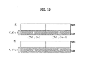
図19は、本発明による少なくとも1チャンネルを持つダウンミックス信号に空間情報を埋め込む第2の方法を示す。図19では、便宜上、2チャンネルを持つダウンミックス信号について説明するが、本発明がこれに限定されることはない。図示のように、第2の方法は、空間情報を1チャンネル(ここでは、左チャンネル)のブロックnにまず埋め込んだ後、他のチャンネル(ここでは、右チャンネル)のブロックnに埋め込み、続いて元チャンネル(左チャンネル)のブロックn+1に再び埋め込む方式で行われる。この場合、シンク情報は一つのチャンネルにのみ埋め込むことができる。ブロック毎に前記空間情報ビットストリームを前記ダウンミックス信号に埋め込むことができるが、復号化過程ではブロック毎またはフレーム毎に前記空間情報ビットストリームを抽出することができる。前記ダウンミックス信号の2チャンネルの信号特性が異なるので、各チャンネルでのマスキング限界値を個別に求め、K値を各チャンネルにそれぞれ割り当てることができる。すなわち、図示のように、一つのチャンネルにはK1を、他のチャンネルにはK2を割り当てることができる。また、前記K値は各ブロック毎に異なっても良い。この場合にも同様に、前記空間情報は各チャンネルに、LSBからビットプレーン(Bit Plane)順に埋め込まれる、または、サンプル順に埋め込むことができる。 FIG. 19 shows a second method of embedding spatial information in a downmix signal having at least one channel according to the present invention. In FIG. 19, for the sake of convenience, a downmix signal having two channels will be described, but the present invention is not limited to this. As shown in the figure, the second method first embeds spatial information in block n of one channel (here, the left channel), and then embeds it in block n of another channel (here, the right channel). This is performed by embedding again in block n + 1 of the original channel (left channel). In this case, the sync information can be embedded only in one channel. Although the spatial information bit stream can be embedded in the downmix signal for each block, the spatial information bit stream can be extracted for each block or frame in a decoding process. Since the signal characteristics of the two channels of the downmix signal are different, the masking limit value in each channel can be obtained individually and a K value can be assigned to each channel. That is, as shown, K 1 can be assigned to one channel and K 2 can be assigned to the other channel. The K value may be different for each block. Similarly, in this case, the spatial information can be embedded in each channel in the order of the bit plane (bit plane) from the LSB or in the order of samples.
図20は、本発明による少なくとも1チャンネルを持つダウンミックス信号に空間情報を埋め込む第3の方法を示す。図20では、2チャンネルを持つダウンミックス信号について説明しているが、本発明はこれに限定されない。図示のように、第3の方法は、空間情報を2チャンネルに分けて埋め込むものの、これをサンプル単位に2チャンネルに交互に埋め込む方式で行われる。なお、2チャンネルの信号特性が異なるので、各チャンネルにおけるマスキング限界値を個別に求め、各K値を各チャンネルにそれぞれ割り当てることができる。すなわち、図示のように、一つのチャンネルにはK1を、他のチャンネルにはK2を割り当てることができる。また、前記K値は、ブロック毎に異なっても良い。例えば、前記空間情報をまず一つのチャンネル(ここでは、左チャンネル)のサンプル1の下位K1ビットにまず埋め、他のチャンネル(ここでは、右チャンネル)のサンプル1の下位K2ビットに埋める。次に、元チャンネル(左チャンネル)のサンプル2の下位K1ビットを再び埋め、他のチャンネル(右チャンネル)のサンプル2の下位K2ビットを埋める。同図で、ブロック内の数字は、空間情報ビットストリームを埋め込む順序を表す。図20では、MSBから埋めるとしたが、LSBから埋めても良い。
FIG. 20 illustrates a third method of embedding spatial information in a downmix signal having at least one channel according to the present invention. Although FIG. 20 illustrates a downmix signal having two channels, the present invention is not limited to this. As shown in the figure, the third method is performed by embedding spatial information in two channels separately, but by embedding the spatial information alternately in two channels in units of samples. Since the signal characteristics of the two channels are different, masking limit values in each channel can be obtained individually and each K value can be assigned to each channel. That is, as shown, K 1 can be assigned to one channel and K 2 can be assigned to the other channel. The K value may be different for each block. For example, the spatial information is first filled in the lower K1 bits of the
図21は、本発明による少なくとも1チャンネルを持つダウンミックス信号に空間情報を埋め込む第4の方法を示す。図21では、2チャンネルを持つダウンミックス信号について説明するが、本発明はこれに限定されない。図示のように、第4の方法は、空間情報を少なくとも1チャンネルに分けて埋め込むものの、それをLSBからビットプレーン単位に2チャンネルに交互に埋め込む方式で行う。なお、2チャンネルの信号特性が異なるので、各チャンネルでのマスキング限界値を個別に求め、K(K1及びK2)値を各チャンネルにそれぞれ割り当てることができる。すなわち、図示のように一つのチャンネルにはK1を、他のチャンネルにはK2を割り当てることができる。 FIG. 21 illustrates a fourth method of embedding spatial information in a downmix signal having at least one channel according to the present invention. Although FIG. 21 illustrates a downmix signal having two channels, the present invention is not limited to this. As shown in the figure, the fourth method embeds spatial information divided into at least one channel, but embeds it alternately in two channels from the LSB in bit plane units. Since the signal characteristics of the two channels are different, the masking limit value for each channel can be obtained individually and the K (K 1 and K 2 ) value can be assigned to each channel. That is, as shown in the figure, one channel can be assigned K 1 and the other channel can be assigned K 2 .
また、前記K値は各ブロック毎に異なっても良い。例えば、まず一つのチャンネル(ここでは、左チャンネル)のサンプル1の最下位1ビットを埋め、他のチャンネル(ここでは、右チャンネル)のサンプル1の最下位1ビットを埋める。次に、元チャンネル(左チャンネル)のサンプル2の最下位1ビットを再び埋め、他のチャンネル(右チャンネル)のサンプル2の最下位1ビットを再び埋める。同図で、ブロック内の数字は、空間情報を埋める順序を表す。
The K value may be different for each block. For example, the least significant 1 bit of
オーディオ信号が補助データ領域がないストレージ媒体(例えば、ステレオCD)に保存されるか、SPDIFのような方式で転送される場合、L/Rチャンネルがサンプル単位にインタリービング(interleaving)されるため、上記第3の方法、第4の方法で保存されている方が、デコーダの立場では受信する順に処理できるので有利である。また、上記第4の方法は、空間情報ビットストリームを再整列する過程でビットプレーン単位に再整列して保存する場合に適用できる。上述のように、2チャンネルに空間情報ビットストリームを分けて埋め込む場合に、K値を各チャンネルに異ならせて割り当てることが可能であるが、この場合、ビットストリーム内に各チャンネル別にK値を個別に転送することが可能である。また、前記K値を複数にして転送する場合、前記K値を符号化する時にディファレンシャル(differential)符号化方法を利用すれば良い。 When the audio signal is stored in a storage medium having no auxiliary data area (for example, stereo CD) or transferred by a method such as SPDIF, the L / R channel is interleaved in units of samples. The third and fourth methods are advantageous because they can be processed in the order of reception from the standpoint of the decoder. The fourth method can be applied to the case where the spatial information bitstream is rearranged and stored in units of bitplanes in the process of rearranging. As described above, when the spatial information bit stream is embedded in two channels separately, the K value can be assigned differently to each channel. In this case, the K value is individually assigned to each channel in the bit stream. Can be transferred to. In addition, when transferring a plurality of K values, a differential encoding method may be used when encoding the K values.
図22は、本発明による少なくとも1チャンネルを持つダウンミックス信号に空間情報を埋め込む第5の方法を示す。図22では、2チャンネルを持つダウンミックス信号について説明しているが、本発明はこれに限定されない。図示のように、第5の方法は、前記空間情報を2チャンネルに分けて埋め込むものの、これら2チャンネルに同じ値を繰り返し挿入する方式で行われる。このとき、前記少なくとも2チャンネルに同じ符号の値を挿入するか、または、符号を反対にして挿入する。例えば、2チャンネルに1の値を挿入するか、または、1と−1の値を交互に挿入することができる。この第5の方法は、少なくとも1チャンネルの最下位挿入ビット(例えば、Kビット)を比較することによって、転送誤りを容易に確認できる長所を持つ。特に、モノオーディオ信号をCDのようなステレオ媒体に転送する場合、ダウンミックス信号のL(left)チャンネルとR(right)チャンネルが同一なため、挿入される空間情報も同一にすることによってロバスト性(robust)の向上などを図ることができる。ここでも同様に、前記空間情報は各チャンネルにLSBからビットプレーン順に埋め込まれても良く、サンプル順に埋め込まれても良い。 FIG. 22 shows a fifth method of embedding spatial information in a downmix signal having at least one channel according to the present invention. Although FIG. 22 illustrates a downmix signal having two channels, the present invention is not limited to this. As shown in the figure, the fifth method is performed by repeatedly inserting the same value into these two channels, although the spatial information is divided into two channels and embedded. At this time, the value of the same sign is inserted into the at least two channels, or the signs are reversed. For example, a value of 1 can be inserted into two channels, or values of 1 and -1 can be inserted alternately. The fifth method has an advantage that a transfer error can be easily confirmed by comparing the least significant insertion bits (for example, K bits) of at least one channel. In particular, when a mono audio signal is transferred to a stereo medium such as a CD, since the L (left) channel and the R (right) channel of the downmix signal are the same, robustness can be achieved by making the inserted spatial information the same. (robust) can be improved. Similarly, the spatial information may be embedded in each channel from the LSB in the bit plane order or may be embedded in the sample order.
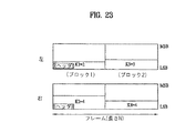
図23は、本発明による少なくとも1チャンネルを持つダウンミックス信号に空間情報を埋め込む第6の方法を示す。第6の方法は、各チャンネルのフレームが複数のブロック(長さB)で構成された場合に、前記空間情報を少なくとも1チャンネルを持つダウンミックス信号に挿入する方法に関する。図示のように、前記挿入ビット長(すなわち、K値)は、各チャンネル毎及びブロック毎にそれぞれ異なる値を持つか、または、同じ値を持つことができる。これらの挿入ビット長(例えば、K1,K2,K3及びK4)は、フレーム全体に対して1回転送されるフレームヘッダ内に保存されることができ、該フレームヘッダはLSBに位置することができる。この場合に、前記ヘッダはビットプレーン単位に挿入することができ、空間情報データはサンプル単位に交互に挿入されるか、または、ブロック単位に交互に挿入することができる。図23は、フレーム内ブロック数が2である場合を示しており、したがって、前記ブロックの大きさ(B)は、N/2となる。この場合、前記フレームに挿入されたビット数は、(K1+K2+K3+K4)*Bとなる。 FIG. 23 shows a sixth method of embedding spatial information in a downmix signal having at least one channel according to the present invention. The sixth method relates to a method of inserting the spatial information into a downmix signal having at least one channel when a frame of each channel is composed of a plurality of blocks (length B). As illustrated, the insertion bit length (that is, the K value) may have a different value for each channel and each block, or may have the same value. These insertion bit lengths (eg, K 1 , K 2 , K 3 and K 4 ) can be stored in a frame header that is transferred once for the entire frame, and the frame header is located in the LSB. can do. In this case, the header can be inserted in bit plane units, and the spatial information data can be inserted alternately in sample units or alternately in block units. FIG. 23 shows a case where the number of blocks in a frame is 2, and therefore the size (B) of the block is N / 2. In this case, the number of bits inserted in the frame is (K 1 + K 2 + K 3 + K 4 ) * B.
図24は、本発明による少なくとも1チャンネルを持つダウンミックス信号に空間情報を埋め込む第7の方法を示す。図24では、2チャンネルを持つダウンミックス信号について説明しているが、本発明はこれに限定されない。図示のように、第7の方法は、前記空間情報を少なくとも2チャンネルに分けて埋め込むものの、それをLSB(または、MSB)からビットプレーン順に2チャンネルに交互に挿入する方法と、サンプル単位に交互に挿入する方法とを混合したものである。この方法は、フレーム単位に行われる、または、図示のようにブロック単位に行われることができる。図24に図示のように、1〜C(ハッチング部分)はヘッダに対応する部分で、挿入フレームシンクワードの探索を容易にするためにLSB(または、MSB)にビットプレーン順に挿入することができる。C+1以上(非ハッチング部分)はヘッダ以外の部分で、空間情報データの読み出しを容易にするためにサンプル単位に2チャンネルに交互に挿入することができる。挿入ビット長(例えば、K値)は、各チャンネル及びブロック毎に異なる値を持つか、または、同じ値を持つことができる。前記挿入ビット長はいずれも、ヘッダ内に含めることができる。 FIG. 24 shows a seventh method of embedding spatial information in a downmix signal having at least one channel according to the present invention. FIG. 24 illustrates a downmix signal having two channels, but the present invention is not limited to this. As shown in the figure, the seventh method embeds the spatial information divided into at least two channels, but alternately inserts the spatial information into the two channels in the bit plane order from the LSB (or MSB), and alternately in units of samples. It is a mixture of the method of inserting into the. This method may be performed on a frame basis or on a block basis as shown. As shown in FIG. 24, 1 to C (hatched portion) are portions corresponding to the header, and can be inserted into the LSB (or MSB) in order of bit planes in order to facilitate the search for the inserted frame sync word. . C + 1 or more (non-hatched part) is a part other than the header, and can be alternately inserted into two channels in units of samples in order to facilitate reading of spatial information data. The insertion bit length (eg, K value) may have a different value for each channel and block, or may have the same value. Any of the insertion bit lengths can be included in the header.
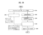
図25は、本発明による少なくとも1チャンネルを持つダウンミックス信号に埋め込まれる空間情報をエンコーディングする方法を示すフローチャートである。まず、マルチチャネルオーディオ信号(2501)からオーディオ信号を少なくとも1チャンネルにダウンミックス(2502)する。また、前記マルチチャネルオーディオ信号(2501)から空間情報を抽出(2503)し、該空間情報を用いて空間情報ビットストリームを生成(2504)する。前記少なくとも1チャンネルを持つダウンミックス信号に前記空間情報ビットストリームを埋め込む(2505)。このとき、空間情報ビットストリームを少なくとも1チャンネルに埋め込む上記の7つの方法のうち、一つ以上の方法を用いることができる。次に、前記空間情報ビットストリームの埋め込まれた前記ダウンミックス信号を含む全体ビットストリームを転送(2506)する。ここで、本発明は、前記ダウンミックス信号を用いてK値を求め、該Kビットに前記空間情報ビットストリームを埋め込むことができる。 FIG. 25 is a flowchart illustrating a method for encoding spatial information embedded in a downmix signal having at least one channel according to the present invention. First, the audio signal is downmixed (2502) to at least one channel from the multichannel audio signal (2501). Also, spatial information is extracted (2503) from the multi-channel audio signal (2501), and a spatial information bit stream is generated (2504) using the spatial information. The spatial information bitstream is embedded in the downmix signal having at least one channel (2505). At this time, one or more of the seven methods described above for embedding the spatial information bitstream in at least one channel can be used. Next, the entire bit stream including the downmix signal in which the spatial information bit stream is embedded is transferred (2506). Here, according to the present invention, a K value can be obtained using the downmix signal, and the spatial information bitstream can be embedded in the K bits.
図26は、本発明による少なくとも1チャンネルを持つダウンミックス信号に埋め込まれた空間情報ビットストリームをデコーディングする方法を示すフローチャートである。まず、空間デコーダは、空間情報ビットストリームの埋め込まれたダウンミックス信号を含むビットストリームを受信(2601)し、該ビットストリームからダウンミックス信号を検出(2602)する。また、前記受信されたビットストリームから、少なくとも1チャンネルを持つダウンミックス信号に埋め込まれた空間情報ビットストリームを抽出し且つデコーディング(2603)する。続いて、前記デコーディングから得られた空間情報を用いて、前記ダウンミックス信号をマルチチャネル信号に変換(2604)する。ここで、本発明は、前記空間情報ビットストリームが埋め込まれた順序に対する識別情報を抽出し、該識別情報を用いて前記空間情報ビットストリームを抽出及びデコーディングすることができる。なお、本発明は、前記ビットストリームからK値に対する情報を読み出し、該K値を用いて前記空間情報ビットストリームをデコーディングすることができる。 FIG. 26 is a flowchart illustrating a method for decoding a spatial information bitstream embedded in a downmix signal having at least one channel according to the present invention. First, the spatial decoder receives a bitstream including a downmix signal in which a spatial information bitstream is embedded (2601), and detects a downmix signal from the bitstream (2602). In addition, a spatial information bit stream embedded in a downmix signal having at least one channel is extracted from the received bit stream and decoded (2603). Subsequently, the spatial information obtained from the decoding is used to convert the downmix signal into a multi-channel signal (2604). Here, the present invention can extract identification information for an order in which the spatial information bitstream is embedded, and extract and decode the spatial information bitstream using the identification information. In the present invention, information on a K value can be read from the bit stream, and the spatial information bit stream can be decoded using the K value.
以上では具体的な実施例に挙げて本発明を説明してきたが、これらの実施例は、本発明を理解するための説明のために提示されたもので、本発明の範囲を制限するためのものではない。本発明の技術的思想の範囲内で本発明の様々な変形が可能であるということは、当該技術分野における通常の知識を持つ者にとっては明らかであり、したがって、本発明の範囲は、添付した特許請求の範囲によって定められるべきである。 Although the present invention has been described with reference to specific embodiments, these embodiments are presented for the purpose of understanding the present invention and are intended to limit the scope of the present invention. It is not a thing. It is apparent to those skilled in the art that various modifications of the present invention are possible within the scope of the technical idea of the present invention, and therefore the scope of the present invention is attached. It should be defined by the scope of the claims.
Claims (23)
前記付加情報を用いて前記オーディオ信号をデコーディングする段階と、
を含むことを特徴とする、オーディオ信号のデコーディング方法。 Extracting additional information embedded in the non-perceptual component of the audio signal component;
Decoding the audio signal using the additional information;
A method for decoding an audio signal, comprising:
前記付加情報に対するヘッダ領域から、あらかじめ指定された大きさの情報を読み出す段階をさらに含むことを特徴とする、請求項1に記載のオーディオ信号のデコーディング方法。 The decoding method is:
The audio signal decoding method according to claim 1, further comprising a step of reading information of a predetermined size from a header area for the additional information.
前記読み出されたヘッダ領域情報のうち、シンクワード以外のヘッダ領域情報に逆白色化技法を適用する段階をさらに含むことを特徴とする、請求項2に記載のオーディオ信号のデコーディング方法。 The decoding method is:
The audio signal decoding method according to claim 2, further comprising applying an inverse whitening technique to header area information other than the sync word in the read header area information.
前記逆白色化技法の適用されたヘッダ領域情報を用いて、前記ヘッダ領域の大きさ情報を得る段階をさらに含むことを特徴とする、請求項3に記載のオーディオ信号のデコーディング方法。 The decoding method is:
The audio signal decoding method according to claim 3, further comprising: obtaining size information of the header region using header region information to which the inverse whitening technique is applied.
前記付加情報の埋め込まれた挿入ビット長を読み出す段階をさらに含むことを特徴とする、請求項1に記載のオーディオ信号のデコーディング方法。 The decoding method is:
The audio signal decoding method according to claim 1, further comprising a step of reading an insertion bit length in which the additional information is embedded.
前記付加情報に逆白色化技法を適用する段階をさらに含むことを特徴とする、請求項1に記載のオーディオ信号のデコーディング方法。 The decoding method is:
The method of claim 1, further comprising applying an inverse whitening technique to the additional information.
前記オーディオ信号に埋め込まれた少なくとも一つの誤り検出コードまたは誤り訂正コードを抽出し、前記抽出された誤り検出コードまたは誤り訂正コードを用いて前記付加情報の損傷の有無を判断する段階をさらに含むことを特徴とする、請求項1に記載のオーディオ信号のデコーディング方法。 The decoding method is:
The method further includes extracting at least one error detection code or error correction code embedded in the audio signal and determining whether the additional information is damaged using the extracted error detection code or error correction code. The audio signal decoding method according to claim 1, wherein:
(b)前記生成された付加情報を、前記オーディオ信号成分のうち非知覚的成分に埋め込む段階と、
を含むことを特徴とする、オーディオ信号のエンコーディング方法。 (A) generating an audio signal and additional information necessary for decoding the audio signal;
(B) embedding the generated additional information in a non-perceptual component of the audio signal component;
A method for encoding an audio signal, comprising:
前記付加情報の埋め込まれる挿入領域に、サンプルプレーン順またはビットプレーン順に前記付加情報を挿入する段階を含むことを特徴とする、請求項11に記載のオーディオ信号のエンコーディング方法。 In step (b),
12. The audio signal encoding method according to claim 11, further comprising the step of inserting the additional information into an insertion area in which the additional information is embedded in order of a sample plane or a bit plane.
前記付加情報を前記挿入領域内で上位ビットから挿入する、または、下位ビットから挿入する段階をさらに含むことを特徴とする、請求項12に記載のオーディオ信号のエンコーディング方法。 In step (b),
The audio signal encoding method according to claim 12, further comprising the step of inserting the additional information from the upper bit or the lower bit in the insertion area.
前記付加情報が埋め込まれる挿入領域を0に入れ替えた後に、前記付加情報を埋め込む段階をさらに含むことを特徴とする、請求項11に記載のオーディオ信号のエンコーディング方法。 In step (b),
12. The audio signal encoding method according to claim 11, further comprising the step of embedding the additional information after replacing the insertion area in which the additional information is embedded with 0.
前記付加情報が埋め込まれる挿入領域から付加情報を引き、前記挿入領域を再量子化した後に、前記付加情報を埋め込む段階をさらに含むことを特徴とする、請求項11に記載のオーディオ信号のエンコーディング方法。 In step (b),
12. The audio signal encoding method according to claim 11, further comprising the step of subtracting the additional information from the insertion area in which the additional information is embedded, re-quantizing the insertion area, and then embedding the additional information. .
前記付加情報を白色化(whitening)する段階をさらに含むことを特徴とする、請求項16に記載のオーディオ信号のエンコーディング方法。 In step (b),
The method of claim 16, further comprising whitening the additional information.
前記空間情報が埋め込まれる挿入領域で、埋め込み可能なビット数よりも埋め込むべき付加情報のビット数が小さい場合には、残りのビットを0で埋めるか、ランダム信号で埋めるか、元のオーディオ信号で埋めるか、テールビット列で埋めるか、または、これらを組み合わせて埋める段階をさらに含むことを特徴とする、請求項11に記載のオーディオ信号のエンコーディング方法。 In step (b),
When the number of bits of additional information to be embedded is smaller than the number of bits that can be embedded in the insertion area in which the spatial information is embedded, the remaining bits are padded with 0, a random signal, or the original audio signal. The audio signal encoding method according to claim 11, further comprising a step of filling, filling with a tail bit string, or a combination thereof.
前記付加情報にノイズシェーピング(noise shaping)技法を適用する段階をさらに含むことを特徴とする、請求項11に記載のオーディオ信号のエンコーディング方法。 The encoding method is:
The method of claim 11, further comprising applying a noise shaping technique to the additional information.
前記オーディオ信号に対する付加情報を抽出する付加情報抽出部と、
前記付加情報を前記オーディオ信号成分のうち非知覚的成分に埋め込む埋め込み部と、
を含むことを特徴とする、オーディオ信号のエンコーディング装置。 An audio signal generator for generating an audio signal;
An additional information extraction unit for extracting additional information for the audio signal;
An embedding unit that embeds the additional information in a non-perceptual component of the audio signal component;
A device for encoding an audio signal, comprising:
前記付加情報ビットストリームをデコーディングして付加情報を生成する付加情報デコーダと、
前記付加情報を用いて前記オーディオ信号をデコーディングするマルチチャネル生成部と、
を含むことを特徴とする、オーディオ信号のデコーディング装置。 An embedded signal decoder that extracts an additional information bitstream embedded in a non-perceptual component of the audio signal component;
An additional information decoder that decodes the additional information bitstream to generate additional information;
A multi-channel generation unit that decodes the audio signal using the additional information;
A device for decoding an audio signal, comprising:
Applications Claiming Priority (8)
| Application Number | Priority Date | Filing Date | Title |
|---|---|---|---|
| US68457805P | 2005-05-26 | 2005-05-26 | |
| US75860806P | 2006-01-13 | 2006-01-13 | |
| US78717206P | 2006-03-30 | 2006-03-30 | |
| KR1020060030660A KR20060122693A (en) | 2005-05-26 | 2006-04-04 | Modulation for insertion length of saptial bitstream into down-mix audio signal |
| KR1020060030658A KR20060122692A (en) | 2005-05-26 | 2006-04-04 | Method of encoding and decoding down-mix audio signal embeded with spatial bitstream |
| KR1020060030661A KR20060122694A (en) | 2005-05-26 | 2006-04-04 | Method of inserting spatial bitstream in at least two channel down-mix audio signal |
| KR1020060046972A KR20060122734A (en) | 2005-05-26 | 2006-05-25 | Encoding and decoding method of audio signal with selectable transmission method of spatial bitstream |
| PCT/KR2006/002018 WO2006126856A2 (en) | 2005-05-26 | 2006-05-26 | Method of encoding and decoding an audio signal |
Publications (2)
| Publication Number | Publication Date |
|---|---|
| JP2008542816A true JP2008542816A (en) | 2008-11-27 |
| JP2008542816A5 JP2008542816A5 (en) | 2009-01-15 |
Family
ID=40148670
Family Applications (4)
| Application Number | Title | Priority Date | Filing Date |
|---|---|---|---|
| JP2008513382A Active JP5118022B2 (en) | 2005-05-26 | 2006-05-26 | Audio signal encoding / decoding method and encoding / decoding device |
| JP2008513380A Active JP5452915B2 (en) | 2005-05-26 | 2006-05-26 | Audio signal encoding / decoding method and encoding / decoding device |
| JP2008513381A Active JP5461835B2 (en) | 2005-05-26 | 2006-05-26 | Audio signal encoding / decoding method and encoding / decoding device |
| JP2008513379A Pending JP2008542816A (en) | 2005-05-26 | 2006-05-26 | Audio signal encoding and decoding method |
Family Applications Before (3)
| Application Number | Title | Priority Date | Filing Date |
|---|---|---|---|
| JP2008513382A Active JP5118022B2 (en) | 2005-05-26 | 2006-05-26 | Audio signal encoding / decoding method and encoding / decoding device |
| JP2008513380A Active JP5452915B2 (en) | 2005-05-26 | 2006-05-26 | Audio signal encoding / decoding method and encoding / decoding device |
| JP2008513381A Active JP5461835B2 (en) | 2005-05-26 | 2006-05-26 | Audio signal encoding / decoding method and encoding / decoding device |
Country Status (4)
| Country | Link |
|---|---|
| US (4) | US8214220B2 (en) |
| EP (4) | EP1897084A2 (en) |
| JP (4) | JP5118022B2 (en) |
| WO (4) | WO2006126859A2 (en) |
Cited By (6)
| Publication number | Priority date | Publication date | Assignee | Title |
|---|---|---|---|---|
| JP2016514394A (en) * | 2013-02-20 | 2016-05-19 | クゥアルコム・インコーポレイテッドQualcomm Incorporated | Remote conferencing using audio data embedded in steganography |
| US9655360B2 (en) | 2004-01-23 | 2017-05-23 | Eden Research Plc | Nematicidal compositions and methods of using them |
| US10258033B2 (en) | 2005-11-30 | 2019-04-16 | Eden Research Plc | Compositions and methods comprising terpenes or terpene mixtures selected from thymol, eugenol, geraniol, citral and L-carvone |
| US10383329B2 (en) | 2012-11-21 | 2019-08-20 | Eden Research Plc | Preservatives |
| US10638750B2 (en) | 2004-05-20 | 2020-05-05 | Eden Research Plc | Compositions containing a hollow glucan particle or a cell wall particle encapsulating a terpene component, methods of making and using them |
| US10667512B2 (en) | 2005-11-30 | 2020-06-02 | Eden Research Plc | Terpene-containing compositions and methods of making and using them |
Families Citing this family (40)
| Publication number | Priority date | Publication date | Assignee | Title |
|---|---|---|---|---|
| KR100754220B1 (en) | 2006-03-07 | 2007-09-03 | 삼성전자주식회사 | Binaural decoder for spatial stereo sound and method for decoding thereof |
| EP2122613B1 (en) | 2006-12-07 | 2019-01-30 | LG Electronics Inc. | A method and an apparatus for processing an audio signal |
| EP2595152A3 (en) * | 2006-12-27 | 2013-11-13 | Electronics and Telecommunications Research Institute | Transkoding apparatus |
| EP2210252B1 (en) | 2007-11-12 | 2017-05-24 | The Nielsen Company (US), LLC | Methods and apparatus to perform audio watermarking and watermark detection and extraction |
| US8457951B2 (en) | 2008-01-29 | 2013-06-04 | The Nielsen Company (Us), Llc | Methods and apparatus for performing variable black length watermarking of media |
| WO2010000313A1 (en) | 2008-07-01 | 2010-01-07 | Nokia Corporation | Apparatus and method for adjusting spatial cue information of a multichannel audio signal |
| TWI475896B (en) | 2008-09-25 | 2015-03-01 | Dolby Lab Licensing Corp | Binaural filters for monophonic compatibility and loudspeaker compatibility |
| JP5309944B2 (en) * | 2008-12-11 | 2013-10-09 | 富士通株式会社 | Audio decoding apparatus, method, and program |
| KR20110138367A (en) * | 2009-03-13 | 2011-12-27 | 코닌클리케 필립스 일렉트로닉스 엔.브이. | Embedding and extracting ancillary data |
| FR2944403B1 (en) * | 2009-04-10 | 2017-02-03 | Inst Polytechnique Grenoble | METHOD AND DEVICE FOR FORMING A MIXED SIGNAL, METHOD AND DEVICE FOR SEPARATING SIGNALS, AND CORRESPONDING SIGNAL |
| US20100324915A1 (en) * | 2009-06-23 | 2010-12-23 | Electronic And Telecommunications Research Institute | Encoding and decoding apparatuses for high quality multi-channel audio codec |
| EP2475116A4 (en) | 2009-09-01 | 2013-11-06 | Panasonic Corp | Digital broadcasting transmission device, digital broadcasting reception device, digital broadcasting reception system |
| US9826266B2 (en) | 2009-09-29 | 2017-11-21 | Universal Electronics Inc. | System and method for reconfiguration of an entertainment system controlling device |
| BR112012008793B1 (en) * | 2009-10-15 | 2021-02-23 | France Telecom | CODIFICATION AND PARAMETRIC DECODING PROCESSES OF A MULTIChannel SIGNAL AUDIO, DIGITAL PARAMETER ENCODER AND DECODER OF A MULTICANAL SIGNAL |
| TWI444989B (en) * | 2010-01-22 | 2014-07-11 | Dolby Lab Licensing Corp | Using multichannel decorrelation for improved multichannel upmixing |
| KR101773631B1 (en) | 2010-06-09 | 2017-08-31 | 파나소닉 인텔렉츄얼 프로퍼티 코포레이션 오브 아메리카 | Band enhancement method, band enhancement apparatus, program, integrated circuit and audio decoder apparatus |
| US9514768B2 (en) * | 2010-08-06 | 2016-12-06 | Samsung Electronics Co., Ltd. | Audio reproducing method, audio reproducing apparatus therefor, and information storage medium |
| FR2966277B1 (en) * | 2010-10-13 | 2017-03-31 | Inst Polytechnique Grenoble | METHOD AND DEVICE FOR FORMING AUDIO DIGITAL MIXED SIGNAL, SIGNAL SEPARATION METHOD AND DEVICE, AND CORRESPONDING SIGNAL |
| EP2686848A1 (en) * | 2011-03-18 | 2014-01-22 | Fraunhofer-Gesellschaft zur Förderung der angewandten Forschung e.V. | Frame element positioning in frames of a bitstream representing audio content |
| US20130108053A1 (en) * | 2011-10-31 | 2013-05-02 | Otto A. Gygax | Generating a stereo audio data packet |
| KR101871234B1 (en) * | 2012-01-02 | 2018-08-02 | 삼성전자주식회사 | Apparatus and method for generating sound panorama |
| EP2873073A1 (en) * | 2012-07-12 | 2015-05-20 | Dolby Laboratories Licensing Corporation | Embedding data in stereo audio using saturation parameter modulation |
| KR102259112B1 (en) * | 2012-11-15 | 2021-05-31 | 가부시키가이샤 엔.티.티.도코모 | Audio coding device, audio coding method, audio coding program, audio decoding device, audio decoding method, and audio decoding program |
| US9854377B2 (en) * | 2013-05-29 | 2017-12-26 | Qualcomm Incorporated | Interpolation for decomposed representations of a sound field |
| GB2515539A (en) | 2013-06-27 | 2014-12-31 | Samsung Electronics Co Ltd | Data structure for physical layer encapsulation |
| US9883311B2 (en) | 2013-06-28 | 2018-01-30 | Dolby Laboratories Licensing Corporation | Rendering of audio objects using discontinuous rendering-matrix updates |
| EP2830065A1 (en) | 2013-07-22 | 2015-01-28 | Fraunhofer-Gesellschaft zur Förderung der angewandten Forschung e.V. | Apparatus and method for decoding an encoded audio signal using a cross-over filter around a transition frequency |
| KR102243395B1 (en) * | 2013-09-05 | 2021-04-22 | 한국전자통신연구원 | Apparatus for encoding audio signal, apparatus for decoding audio signal, and apparatus for replaying audio signal |
| WO2015147619A1 (en) | 2014-03-28 | 2015-10-01 | 삼성전자 주식회사 | Method and apparatus for rendering acoustic signal, and computer-readable recording medium |
| EP3301673A1 (en) * | 2016-09-30 | 2018-04-04 | Nxp B.V. | Audio communication method and apparatus |
| GB201617409D0 (en) | 2016-10-13 | 2016-11-30 | Asio Ltd | A method and system for acoustic communication of data |
| GB201617408D0 (en) | 2016-10-13 | 2016-11-30 | Asio Ltd | A method and system for acoustic communication of data |
| US10339947B2 (en) | 2017-03-22 | 2019-07-02 | Immersion Networks, Inc. | System and method for processing audio data |
| GB201704636D0 (en) | 2017-03-23 | 2017-05-10 | Asio Ltd | A method and system for authenticating a device |
| GB2565751B (en) | 2017-06-15 | 2022-05-04 | Sonos Experience Ltd | A method and system for triggering events |
| GB2570634A (en) * | 2017-12-20 | 2019-08-07 | Asio Ltd | A method and system for improved acoustic transmission of data |
| CN112166569B (en) * | 2018-06-07 | 2022-05-13 | 华为技术有限公司 | Data transmission method and device |
| US11239988B2 (en) * | 2019-04-22 | 2022-02-01 | Texas Instruments Incorporated | Methods and systems for synchronization of slave device with master device |
| JP7419778B2 (en) | 2019-12-06 | 2024-01-23 | ヤマハ株式会社 | Audio signal output device, audio system and audio signal output method |
| JP7282066B2 (en) * | 2020-10-26 | 2023-05-26 | 株式会社日立製作所 | Data compression device and data compression method |
Citations (3)
| Publication number | Priority date | Publication date | Assignee | Title |
|---|---|---|---|---|
| JP2002521739A (en) * | 1998-07-29 | 2002-07-16 | ブリティッシュ・ブロードキャスティング・コーポレーション | Method of inserting sub data into audio data stream |
| JP2004110770A (en) * | 2002-06-11 | 2004-04-08 | Matsushita Electric Ind Co Ltd | Content delivery system and data communication control device |
| WO2004090868A1 (en) * | 2003-04-08 | 2004-10-21 | Koninklijke Philips Electronics N.V. | Updating of a buried data channel |
Family Cites Families (126)
| Publication number | Priority date | Publication date | Assignee | Title |
|---|---|---|---|---|
| JPS6096079A (en) | 1983-10-31 | 1985-05-29 | Matsushita Electric Ind Co Ltd | Encoding method of multivalue picture |
| US4661862A (en) * | 1984-04-27 | 1987-04-28 | Rca Corporation | Differential PCM video transmission system employing horizontally offset five pixel groups and delta signals having plural non-linear encoding functions |
| US4621862A (en) * | 1984-10-22 | 1986-11-11 | The Coca-Cola Company | Closing means for trucks |
| JPS6294090A (en) | 1985-10-21 | 1987-04-30 | Hitachi Ltd | Encoding device |
| US4725885A (en) * | 1986-12-22 | 1988-02-16 | International Business Machines Corporation | Adaptive graylevel image compression system |
| JPH0793584B2 (en) | 1987-09-25 | 1995-10-09 | 株式会社日立製作所 | Encoder |
| NL8901032A (en) | 1988-11-10 | 1990-06-01 | Philips Nv | CODER FOR INCLUDING ADDITIONAL INFORMATION IN A DIGITAL AUDIO SIGNAL WITH A PREFERRED FORMAT, A DECODER FOR DERIVING THIS ADDITIONAL INFORMATION FROM THIS DIGITAL SIGNAL, AN APPARATUS FOR RECORDING A DIGITAL SIGNAL ON A CODE OF RECORD. OBTAINED A RECORD CARRIER WITH THIS DEVICE. |
| US5243686A (en) * | 1988-12-09 | 1993-09-07 | Oki Electric Industry Co., Ltd. | Multi-stage linear predictive analysis method for feature extraction from acoustic signals |
| CA2140678C (en) | 1989-01-27 | 2001-05-01 | Louis Dunn Fielder | Coder and decoder for high-quality audio |
| DE3943879B4 (en) | 1989-04-17 | 2008-07-17 | Fraunhofer-Gesellschaft zur Förderung der angewandten Forschung e.V. | Digital coding method |
| US6289308B1 (en) * | 1990-06-01 | 2001-09-11 | U.S. Philips Corporation | Encoded wideband digital transmission signal and record carrier recorded with such a signal |
| NL9000338A (en) * | 1989-06-02 | 1991-01-02 | Koninkl Philips Electronics Nv | DIGITAL TRANSMISSION SYSTEM, TRANSMITTER AND RECEIVER FOR USE IN THE TRANSMISSION SYSTEM AND RECORD CARRIED OUT WITH THE TRANSMITTER IN THE FORM OF A RECORDING DEVICE. |
| GB8921320D0 (en) | 1989-09-21 | 1989-11-08 | British Broadcasting Corp | Digital video coding |
| EP0520068B1 (en) | 1991-01-08 | 1996-05-15 | Dolby Laboratories Licensing Corporation | Encoder/decoder for multidimensional sound fields |
| ES2164640T3 (en) * | 1991-08-02 | 2002-03-01 | Sony Corp | DIGITAL ENCODER WITH DYNAMIC ASSIGNMENT OF QUANTIFICATION BITS. |
| DE4209544A1 (en) * | 1992-03-24 | 1993-09-30 | Inst Rundfunktechnik Gmbh | Method for transmitting or storing digitized, multi-channel audio signals |
| JP3104400B2 (en) | 1992-04-27 | 2000-10-30 | ソニー株式会社 | Audio signal encoding apparatus and method |
| US5890190A (en) * | 1992-12-31 | 1999-03-30 | Intel Corporation | Frame buffer for storing graphics and video data |
| JP3123286B2 (en) * | 1993-02-18 | 2001-01-09 | ソニー株式会社 | Digital signal processing device or method, and recording medium |
| US5481643A (en) * | 1993-03-18 | 1996-01-02 | U.S. Philips Corporation | Transmitter, receiver and record carrier for transmitting/receiving at least a first and a second signal component |
| US5563661A (en) * | 1993-04-05 | 1996-10-08 | Canon Kabushiki Kaisha | Image processing apparatus |
| US6125398A (en) * | 1993-11-24 | 2000-09-26 | Intel Corporation | Communications subsystem for computer-based conferencing system using both ISDN B channels for transmission |
| US5488570A (en) | 1993-11-24 | 1996-01-30 | Intel Corporation | Encoding and decoding video signals using adaptive filter switching criteria |
| US5640159A (en) * | 1994-01-03 | 1997-06-17 | International Business Machines Corporation | Quantization method for image data compression employing context modeling algorithm |
| RU2158970C2 (en) | 1994-03-01 | 2000-11-10 | Сони Корпорейшн | Method for digital signal encoding and device which implements said method, carrier for digital signal recording, method for digital signal decoding and device which implements said method |
| JP3498375B2 (en) * | 1994-07-20 | 2004-02-16 | ソニー株式会社 | Digital audio signal recording device |
| US6549666B1 (en) * | 1994-09-21 | 2003-04-15 | Ricoh Company, Ltd | Reversible embedded wavelet system implementation |
| JPH08123494A (en) | 1994-10-28 | 1996-05-17 | Mitsubishi Electric Corp | Speech encoding device, speech decoding device, speech encoding and decoding method, and phase amplitude characteristic derivation device usable for same |
| JPH08130649A (en) | 1994-11-01 | 1996-05-21 | Canon Inc | Data processing unit |
| KR100209877B1 (en) * | 1994-11-26 | 1999-07-15 | 윤종용 | Variable length coding encoder and decoder using multiple huffman table |
| JP3371590B2 (en) | 1994-12-28 | 2003-01-27 | ソニー株式会社 | High efficiency coding method and high efficiency decoding method |
| JP3484832B2 (en) | 1995-08-02 | 2004-01-06 | ソニー株式会社 | Recording apparatus, recording method, reproducing apparatus and reproducing method |
| US5956674A (en) * | 1995-12-01 | 1999-09-21 | Digital Theater Systems, Inc. | Multi-channel predictive subband audio coder using psychoacoustic adaptive bit allocation in frequency, time and over the multiple channels |
| US6047027A (en) | 1996-02-07 | 2000-04-04 | Matsushita Electric Industrial Co., Ltd. | Packetized data stream decoder using timing information extraction and insertion |
| JP3088319B2 (en) | 1996-02-07 | 2000-09-18 | 松下電器産業株式会社 | Decoding device and decoding method |
| US6399760B1 (en) * | 1996-04-12 | 2002-06-04 | Millennium Pharmaceuticals, Inc. | RP compositions and therapeutic and diagnostic uses therefor |
| EP0827312A3 (en) | 1996-08-22 | 2003-10-01 | Marconi Communications GmbH | Method for changing the configuration of data packets |
| US5912636A (en) * | 1996-09-26 | 1999-06-15 | Ricoh Company, Ltd. | Apparatus and method for performing m-ary finite state machine entropy coding |
| US5893066A (en) | 1996-10-15 | 1999-04-06 | Samsung Electronics Co. Ltd. | Fast requantization apparatus and method for MPEG audio decoding |
| TW429700B (en) | 1997-02-26 | 2001-04-11 | Sony Corp | Information encoding method and apparatus, information decoding method and apparatus and information recording medium |
| US6134518A (en) | 1997-03-04 | 2000-10-17 | International Business Machines Corporation | Digital audio signal coding using a CELP coder and a transform coder |
| US6131084A (en) | 1997-03-14 | 2000-10-10 | Digital Voice Systems, Inc. | Dual subframe quantization of spectral magnitudes |
| US6639945B2 (en) * | 1997-03-14 | 2003-10-28 | Microsoft Corporation | Method and apparatus for implementing motion detection in video compression |
| US6356639B1 (en) | 1997-04-11 | 2002-03-12 | Matsushita Electric Industrial Co., Ltd. | Audio decoding apparatus, signal processing device, sound image localization device, sound image control method, audio signal processing device, and audio signal high-rate reproduction method used for audio visual equipment |
| US5890125A (en) * | 1997-07-16 | 1999-03-30 | Dolby Laboratories Licensing Corporation | Method and apparatus for encoding and decoding multiple audio channels at low bit rates using adaptive selection of encoding method |
| EP0903744B1 (en) * | 1997-09-17 | 2001-01-10 | Matsushita Electric Industrial Co., Ltd | Optical disc, video data editing apparatus, computer-readable recording medium storing an editing program, reproduction apparatus for the optical disc, and computer-readable recording medium storing a reproduction program |
| US6130418A (en) | 1997-10-06 | 2000-10-10 | U.S. Philips Corporation | Optical scanning unit having a main lens and an auxiliary lens |
| US5966688A (en) | 1997-10-28 | 1999-10-12 | Hughes Electronics Corporation | Speech mode based multi-stage vector quantizer |
| JP2005063655A (en) | 1997-11-28 | 2005-03-10 | Victor Co Of Japan Ltd | Encoding method and decoding method of audio signal |
| JP3022462B2 (en) | 1998-01-13 | 2000-03-21 | 興和株式会社 | Vibration wave encoding method and decoding method |
| ATE302991T1 (en) | 1998-01-22 | 2005-09-15 | Deutsche Telekom Ag | METHOD FOR SIGNAL-CONTROLLED SWITCHING BETWEEN DIFFERENT AUDIO CODING SYSTEMS |
| JPH11282496A (en) * | 1998-03-30 | 1999-10-15 | Matsushita Electric Ind Co Ltd | Decoding device |
| US6339760B1 (en) * | 1998-04-28 | 2002-01-15 | Hitachi, Ltd. | Method and system for synchronization of decoded audio and video by adding dummy data to compressed audio data |
| JPH11330980A (en) | 1998-05-13 | 1999-11-30 | Matsushita Electric Ind Co Ltd | Decoding device and method and recording medium recording decoding procedure |
| MY118961A (en) | 1998-09-03 | 2005-02-28 | Sony Corp | Beam irradiation apparatus, optical apparatus having beam irradiation apparatus for information recording medium, method for manufacturing original disk for information recording medium, and method for manufacturing information recording medium |
| US6298071B1 (en) * | 1998-09-03 | 2001-10-02 | Diva Systems Corporation | Method and apparatus for processing variable bit rate information in an information distribution system |
| US6148283A (en) | 1998-09-23 | 2000-11-14 | Qualcomm Inc. | Method and apparatus using multi-path multi-stage vector quantizer |
| US6553147B2 (en) * | 1998-10-05 | 2003-04-22 | Sarnoff Corporation | Apparatus and method for data partitioning to improving error resilience |
| US6556685B1 (en) * | 1998-11-06 | 2003-04-29 | Harman Music Group | Companding noise reduction system with simultaneous encode and decode |
| US6757659B1 (en) | 1998-11-16 | 2004-06-29 | Victor Company Of Japan, Ltd. | Audio signal processing apparatus |
| JP3346556B2 (en) | 1998-11-16 | 2002-11-18 | 日本ビクター株式会社 | Audio encoding method and audio decoding method |
| US6195024B1 (en) * | 1998-12-11 | 2001-02-27 | Realtime Data, Llc | Content independent data compression method and system |
| US6208276B1 (en) * | 1998-12-30 | 2001-03-27 | At&T Corporation | Method and apparatus for sample rate pre- and post-processing to achieve maximal coding gain for transform-based audio encoding and decoding |
| US6631352B1 (en) * | 1999-01-08 | 2003-10-07 | Matushita Electric Industrial Co. Ltd. | Decoding circuit and reproduction apparatus which mutes audio after header parameter changes |
| JP4610087B2 (en) * | 1999-04-07 | 2011-01-12 | ドルビー・ラボラトリーズ・ライセンシング・コーポレーション | Matrix improvement to lossless encoding / decoding |
| JP3323175B2 (en) | 1999-04-20 | 2002-09-09 | 松下電器産業株式会社 | Encoding device |
| US6421467B1 (en) * | 1999-05-28 | 2002-07-16 | Texas Tech University | Adaptive vector quantization/quantizer |
| KR100307596B1 (en) | 1999-06-10 | 2001-11-01 | 윤종용 | Lossless coding and decoding apparatuses of digital audio data |
| JP2001006291A (en) * | 1999-06-21 | 2001-01-12 | Fuji Film Microdevices Co Ltd | Encoding system judging device of audio signal and encoding system judging method for audio signal |
| JP3762579B2 (en) | 1999-08-05 | 2006-04-05 | 株式会社リコー | Digital audio signal encoding apparatus, digital audio signal encoding method, and medium on which digital audio signal encoding program is recorded |
| US20020049586A1 (en) * | 2000-09-11 | 2002-04-25 | Kousuke Nishio | Audio encoder, audio decoder, and broadcasting system |
| US6636830B1 (en) * | 2000-11-22 | 2003-10-21 | Vialta Inc. | System and method for noise reduction using bi-orthogonal modified discrete cosine transform |
| JP4008244B2 (en) | 2001-03-02 | 2007-11-14 | 松下電器産業株式会社 | Encoding device and decoding device |
| JP3566220B2 (en) | 2001-03-09 | 2004-09-15 | 三菱電機株式会社 | Speech coding apparatus, speech coding method, speech decoding apparatus, and speech decoding method |
| US7583805B2 (en) | 2004-02-12 | 2009-09-01 | Agere Systems Inc. | Late reverberation-based synthesis of auditory scenes |
| US7292901B2 (en) | 2002-06-24 | 2007-11-06 | Agere Systems Inc. | Hybrid multi-channel/cue coding/decoding of audio signals |
| US7644003B2 (en) * | 2001-05-04 | 2010-01-05 | Agere Systems Inc. | Cue-based audio coding/decoding |
| JP2002335230A (en) | 2001-05-11 | 2002-11-22 | Victor Co Of Japan Ltd | Method and device for decoding audio encoded signal |
| JP2003005797A (en) | 2001-06-21 | 2003-01-08 | Matsushita Electric Ind Co Ltd | Method and device for encoding audio signal, and system for encoding and decoding audio signal |
| GB0119569D0 (en) * | 2001-08-13 | 2001-10-03 | Radioscape Ltd | Data hiding in digital audio broadcasting (DAB) |
| EP1308931A1 (en) | 2001-10-23 | 2003-05-07 | Deutsche Thomson-Brandt Gmbh | Decoding of a digital audio signal organised in frames comprising a header |
| EP1315148A1 (en) * | 2001-11-17 | 2003-05-28 | Deutsche Thomson-Brandt Gmbh | Determination of the presence of ancillary data in an audio bitstream |
| KR100480787B1 (en) | 2001-11-27 | 2005-04-07 | 삼성전자주식회사 | Encoding/decoding method and apparatus for key value of coordinate interpolator node |
| EP1466320B1 (en) | 2001-11-30 | 2007-02-07 | Koninklijke Philips Electronics N.V. | Signal coding |
| TW569550B (en) | 2001-12-28 | 2004-01-01 | Univ Nat Central | Method of inverse-modified discrete cosine transform and overlap-add for MPEG layer 3 voice signal decoding and apparatus thereof |
| CA2574127A1 (en) * | 2002-01-18 | 2003-07-31 | Kabushiki Kaisha Toshiba | Video encoding method and apparatus and video decoding method and apparatus |
| JP2003233395A (en) | 2002-02-07 | 2003-08-22 | Matsushita Electric Ind Co Ltd | Method and device for encoding audio signal and encoding and decoding system |
| AU2003213439A1 (en) | 2002-03-08 | 2003-09-22 | Nippon Telegraph And Telephone Corporation | Digital signal encoding method, decoding method, encoding device, decoding device, digital signal encoding program, and decoding program |
| DE60307252T2 (en) | 2002-04-11 | 2007-07-19 | Matsushita Electric Industrial Co., Ltd., Kadoma | DEVICES, METHODS AND PROGRAMS FOR CODING AND DECODING |
| US7275036B2 (en) * | 2002-04-18 | 2007-09-25 | Fraunhofer-Gesellschaft Zur Foerderung Der Angewandten Forschung E.V. | Apparatus and method for coding a time-discrete audio signal to obtain coded audio data and for decoding coded audio data |
| KR100981699B1 (en) | 2002-07-12 | 2010-09-13 | 코닌클리케 필립스 일렉트로닉스 엔.브이. | Audio coding |
| KR20050021484A (en) | 2002-07-16 | 2005-03-07 | 코닌클리케 필립스 일렉트로닉스 엔.브이. | Audio coding |
| KR100602975B1 (en) | 2002-07-19 | 2006-07-20 | 닛본 덴끼 가부시끼가이샤 | Audio decoding apparatus and decoding method and computer-readable recording medium |
| PL373120A1 (en) | 2002-08-07 | 2005-08-08 | Dolby Laboratories Licensing Corporation | Audio channel spatial translation |
| US7536305B2 (en) | 2002-09-04 | 2009-05-19 | Microsoft Corporation | Mixed lossless audio compression |
| US7502743B2 (en) | 2002-09-04 | 2009-03-10 | Microsoft Corporation | Multi-channel audio encoding and decoding with multi-channel transform selection |
| TW567466B (en) | 2002-09-13 | 2003-12-21 | Inventec Besta Co Ltd | Method using computer to compress and encode audio data |
| CN100401778C (en) | 2002-09-17 | 2008-07-09 | 弗拉迪米尔·切佩尔科维奇 | Fast CODEC with high compression ratio and minimum required resources |
| JP4084990B2 (en) | 2002-11-19 | 2008-04-30 | 株式会社ケンウッド | Encoding device, decoding device, encoding method and decoding method |
| JP2004220743A (en) | 2003-01-17 | 2004-08-05 | Sony Corp | Information recording device, information recording control method, information reproducing device, information reproduction control method |
| JP4431568B2 (en) | 2003-02-11 | 2010-03-17 | コーニンクレッカ フィリップス エレクトロニクス エヌ ヴィ | Speech coding |
| EP1611772A1 (en) | 2003-03-04 | 2006-01-04 | Nokia Corporation | Support of a multichannel audio extension |
| US20040199276A1 (en) * | 2003-04-03 | 2004-10-07 | Wai-Leong Poon | Method and apparatus for audio synchronization |
| KR20050121733A (en) | 2003-04-17 | 2005-12-27 | 코닌클리케 필립스 일렉트로닉스 엔.브이. | Audio signal generation |
| RU2335022C2 (en) * | 2003-07-21 | 2008-09-27 | Фраунхофер-Гезелльшафт Цур Фердерунг Дер Ангевандтен Форшунг Е.Ф. | Transformation of audio file format |
| JP2005086486A (en) * | 2003-09-09 | 2005-03-31 | Alpine Electronics Inc | Audio system and audio processing method |
| US7447317B2 (en) * | 2003-10-02 | 2008-11-04 | Fraunhofer-Gesellschaft Zur Foerderung Der Angewandten Forschung E.V | Compatible multi-channel coding/decoding by weighting the downmix channel |
| ATE354160T1 (en) * | 2003-10-30 | 2007-03-15 | Koninkl Philips Electronics Nv | AUDIO SIGNAL ENCODING OR DECODING |
| US20050137729A1 (en) * | 2003-12-18 | 2005-06-23 | Atsuhiro Sakurai | Time-scale modification stereo audio signals |
| SE527670C2 (en) * | 2003-12-19 | 2006-05-09 | Ericsson Telefon Ab L M | Natural fidelity optimized coding with variable frame length |
| US7394903B2 (en) * | 2004-01-20 | 2008-07-01 | Fraunhofer-Gesellschaft Zur Forderung Der Angewandten Forschung E.V. | Apparatus and method for constructing a multi-channel output signal or for generating a downmix signal |
| US20050174269A1 (en) * | 2004-02-05 | 2005-08-11 | Broadcom Corporation | Huffman decoder used for decoding both advanced audio coding (AAC) and MP3 audio |
| US7392195B2 (en) | 2004-03-25 | 2008-06-24 | Dts, Inc. | Lossless multi-channel audio codec |
| US7813571B2 (en) * | 2004-04-22 | 2010-10-12 | Mitsubishi Electric Corporation | Image encoding apparatus and image decoding apparatus |
| JP2005332449A (en) | 2004-05-18 | 2005-12-02 | Sony Corp | Optical pickup device, optical recording and reproducing device and tilt control method |
| TWM257575U (en) | 2004-05-26 | 2005-02-21 | Aimtron Technology Corp | Encoder and decoder for audio and video information |
| JP2006012301A (en) * | 2004-06-25 | 2006-01-12 | Sony Corp | Optical recording/reproducing method, optical pickup device, optical recording/reproducing device, method for manufacturing optical recording medium, and semiconductor laser device |
| US7391870B2 (en) * | 2004-07-09 | 2008-06-24 | Fraunhofer-Gesellschaft Zur Foerderung Der Angewandten Forschung E V | Apparatus and method for generating a multi-channel output signal |
| DE102004042819A1 (en) * | 2004-09-03 | 2006-03-23 | Fraunhofer-Gesellschaft zur Förderung der angewandten Forschung e.V. | Apparatus and method for generating a coded multi-channel signal and apparatus and method for decoding a coded multi-channel signal |
| US8204261B2 (en) * | 2004-10-20 | 2012-06-19 | Fraunhofer-Gesellschaft Zur Foerderung Der Angewandten Forschung E.V. | Diffuse sound shaping for BCC schemes and the like |
| JP2006120247A (en) | 2004-10-21 | 2006-05-11 | Sony Corp | Condenser lens and its manufacturing method, exposure apparatus using same, optical pickup apparatus, and optical recording and reproducing apparatus |
| US7573912B2 (en) * | 2005-02-22 | 2009-08-11 | Fraunhofer-Gesellschaft Zur Foerderung Der Angewandten Forschunng E.V. | Near-transparent or transparent multi-channel encoder/decoder scheme |
| US7991610B2 (en) | 2005-04-13 | 2011-08-02 | Fraunhofer-Gesellschaft Zur Foerderung Der Angewandten Forschung E.V. | Adaptive grouping of parameters for enhanced coding efficiency |
| KR100803205B1 (en) | 2005-07-15 | 2008-02-14 | 삼성전자주식회사 | Method and apparatus for encoding/decoding audio signal |
| JP4876574B2 (en) * | 2005-12-26 | 2012-02-15 | ソニー株式会社 | Signal encoding apparatus and method, signal decoding apparatus and method, program, and recording medium |
| EP1971978B1 (en) | 2006-01-09 | 2010-08-04 | Nokia Corporation | Controlling the decoding of binaural audio signals |
-
2006
- 2006-05-26 US US11/915,555 patent/US8214220B2/en active Active
- 2006-05-26 WO PCT/KR2006/002021 patent/WO2006126859A2/en active Application Filing
- 2006-05-26 WO PCT/KR2006/002019 patent/WO2006126857A2/en active Application Filing
- 2006-05-26 EP EP06747468A patent/EP1897084A2/en not_active Withdrawn
- 2006-05-26 US US11/915,325 patent/US8090586B2/en active Active
- 2006-05-26 JP JP2008513382A patent/JP5118022B2/en active Active
- 2006-05-26 EP EP06747465A patent/EP1899959A2/en not_active Ceased
- 2006-05-26 WO PCT/KR2006/002020 patent/WO2006126858A2/en active Application Filing
- 2006-05-26 US US11/915,574 patent/US8150701B2/en active Active
- 2006-05-26 EP EP06747467A patent/EP1899960A2/en not_active Ceased
- 2006-05-26 JP JP2008513380A patent/JP5452915B2/en active Active
- 2006-05-26 US US11/915,562 patent/US8170883B2/en active Active
- 2006-05-26 EP EP06747466A patent/EP1905004A2/en not_active Ceased
- 2006-05-26 JP JP2008513381A patent/JP5461835B2/en active Active
- 2006-05-26 WO PCT/KR2006/002018 patent/WO2006126856A2/en active Application Filing
- 2006-05-26 JP JP2008513379A patent/JP2008542816A/en active Pending
Patent Citations (3)
| Publication number | Priority date | Publication date | Assignee | Title |
|---|---|---|---|---|
| JP2002521739A (en) * | 1998-07-29 | 2002-07-16 | ブリティッシュ・ブロードキャスティング・コーポレーション | Method of inserting sub data into audio data stream |
| JP2004110770A (en) * | 2002-06-11 | 2004-04-08 | Matsushita Electric Ind Co Ltd | Content delivery system and data communication control device |
| WO2004090868A1 (en) * | 2003-04-08 | 2004-10-21 | Koninklijke Philips Electronics N.V. | Updating of a buried data channel |
Cited By (8)
| Publication number | Priority date | Publication date | Assignee | Title |
|---|---|---|---|---|
| US9655360B2 (en) | 2004-01-23 | 2017-05-23 | Eden Research Plc | Nematicidal compositions and methods of using them |
| US10004229B2 (en) | 2004-01-23 | 2018-06-26 | Eden Research Plc | Nematicidal compositions and methods of using them |
| US10729130B2 (en) | 2004-01-23 | 2020-08-04 | Eden Research Plc | Nematicidal compositions and methods of using them |
| US10638750B2 (en) | 2004-05-20 | 2020-05-05 | Eden Research Plc | Compositions containing a hollow glucan particle or a cell wall particle encapsulating a terpene component, methods of making and using them |
| US10258033B2 (en) | 2005-11-30 | 2019-04-16 | Eden Research Plc | Compositions and methods comprising terpenes or terpene mixtures selected from thymol, eugenol, geraniol, citral and L-carvone |
| US10667512B2 (en) | 2005-11-30 | 2020-06-02 | Eden Research Plc | Terpene-containing compositions and methods of making and using them |
| US10383329B2 (en) | 2012-11-21 | 2019-08-20 | Eden Research Plc | Preservatives |
| JP2016514394A (en) * | 2013-02-20 | 2016-05-19 | クゥアルコム・インコーポレイテッドQualcomm Incorporated | Remote conferencing using audio data embedded in steganography |
Also Published As
| Publication number | Publication date |
|---|---|
| JP5118022B2 (en) | 2013-01-16 |
| JP2008542817A (en) | 2008-11-27 |
| WO2006126856A2 (en) | 2006-11-30 |
| US8090586B2 (en) | 2012-01-03 |
| WO2006126856A3 (en) | 2007-01-11 |
| WO2006126857A2 (en) | 2006-11-30 |
| WO2006126858A3 (en) | 2007-01-11 |
| US20090055196A1 (en) | 2009-02-26 |
| WO2006126859A2 (en) | 2006-11-30 |
| EP1897084A2 (en) | 2008-03-12 |
| US8170883B2 (en) | 2012-05-01 |
| EP1899959A2 (en) | 2008-03-19 |
| US20090234656A1 (en) | 2009-09-17 |
| WO2006126859A3 (en) | 2007-01-11 |
| EP1905004A2 (en) | 2008-04-02 |
| JP5452915B2 (en) | 2014-03-26 |
| WO2006126858A2 (en) | 2006-11-30 |
| US20090119110A1 (en) | 2009-05-07 |
| JP2008542819A (en) | 2008-11-27 |
| WO2006126857A3 (en) | 2007-01-11 |
| JP5461835B2 (en) | 2014-04-02 |
| JP2008542818A (en) | 2008-11-27 |
| US20090216541A1 (en) | 2009-08-27 |
| EP1899960A2 (en) | 2008-03-19 |
| US8150701B2 (en) | 2012-04-03 |
| US8214220B2 (en) | 2012-07-03 |
Similar Documents
| Publication | Publication Date | Title |
|---|---|---|
| JP5452915B2 (en) | Audio signal encoding / decoding method and encoding / decoding device | |
| KR100717598B1 (en) | Frequency-based coding of audio channels in parametric multi-channel coding systems | |
| CN101253550B (en) | Method of encoding and decoding an audio signal | |
| KR101315077B1 (en) | Scalable multi-channel audio coding | |
| US11200906B2 (en) | Audio encoding method, to which BRIR/RIR parameterization is applied, and method and device for reproducing audio by using parameterized BRIR/RIR information | |
| KR101837084B1 (en) | Method for signal processing, encoding apparatus thereof, decoding apparatus thereof, and information storage medium | |
| KR20060122692A (en) | Method of encoding and decoding down-mix audio signal embeded with spatial bitstream | |
| US20080288263A1 (en) | Method and Apparatus for Encoding/Decoding | |
| KR20070003544A (en) | Clipping restoration by arbitrary downmix gain | |
| KR100891666B1 (en) | Apparatus for processing audio signal and method thereof |
Legal Events
| Date | Code | Title | Description |
|---|---|---|---|
| A521 | Request for written amendment filed |
Free format text: JAPANESE INTERMEDIATE CODE: A523 Effective date: 20080924 |
|
| A131 | Notification of reasons for refusal |
Free format text: JAPANESE INTERMEDIATE CODE: A131 Effective date: 20110111 |
|
| A521 | Request for written amendment filed |
Free format text: JAPANESE INTERMEDIATE CODE: A523 Effective date: 20110411 |
|
| A131 | Notification of reasons for refusal |
Free format text: JAPANESE INTERMEDIATE CODE: A131 Effective date: 20120110 |
|
| A521 | Request for written amendment filed |
Free format text: JAPANESE INTERMEDIATE CODE: A523 Effective date: 20120322 |
|
| A02 | Decision of refusal |
Free format text: JAPANESE INTERMEDIATE CODE: A02 Effective date: 20120911 |