JP2008538480A - Method and apparatus for transmitting and receiving packet data using a preset length indicator in a mobile communication system - Google Patents
Method and apparatus for transmitting and receiving packet data using a preset length indicator in a mobile communication system Download PDFInfo
- Publication number
- JP2008538480A JP2008538480A JP2008507565A JP2008507565A JP2008538480A JP 2008538480 A JP2008538480 A JP 2008538480A JP 2008507565 A JP2008507565 A JP 2008507565A JP 2008507565 A JP2008507565 A JP 2008507565A JP 2008538480 A JP2008538480 A JP 2008538480A
- Authority
- JP
- Japan
- Prior art keywords
- field
- pdu
- sdu
- data
- rlc
- Prior art date
- Legal status (The legal status is an assumption and is not a legal conclusion. Google has not performed a legal analysis and makes no representation as to the accuracy of the status listed.)
- Granted
Links
- 238000000034 method Methods 0.000 title claims abstract description 36
- 238000010295 mobile communication Methods 0.000 title claims abstract description 19
- 230000005540 biological transmission Effects 0.000 claims abstract description 41
- 238000003780 insertion Methods 0.000 claims description 19
- 230000037431 insertion Effects 0.000 claims description 19
- 239000000284 extract Substances 0.000 claims description 2
- 238000009432 framing Methods 0.000 description 25
- 238000010586 diagram Methods 0.000 description 9
- 238000004891 communication Methods 0.000 description 8
- 238000012545 processing Methods 0.000 description 3
- 230000000694 effects Effects 0.000 description 2
- 230000011218 segmentation Effects 0.000 description 2
- 230000003044 adaptive effect Effects 0.000 description 1
- 230000006835 compression Effects 0.000 description 1
- 238000007906 compression Methods 0.000 description 1
- 238000007796 conventional method Methods 0.000 description 1
- 238000012986 modification Methods 0.000 description 1
- 230000004048 modification Effects 0.000 description 1
Images


Classifications
-
- H—ELECTRICITY
- H04—ELECTRIC COMMUNICATION TECHNIQUE
- H04W—WIRELESS COMMUNICATION NETWORKS
- H04W28/00—Network traffic management; Network resource management
- H04W28/02—Traffic management, e.g. flow control or congestion control
- H04W28/06—Optimizing the usage of the radio link, e.g. header compression, information sizing, discarding information
-
- H—ELECTRICITY
- H04—ELECTRIC COMMUNICATION TECHNIQUE
- H04L—TRANSMISSION OF DIGITAL INFORMATION, e.g. TELEGRAPHIC COMMUNICATION
- H04L1/00—Arrangements for detecting or preventing errors in the information received
- H04L1/12—Arrangements for detecting or preventing errors in the information received by using return channel
- H04L1/16—Arrangements for detecting or preventing errors in the information received by using return channel in which the return channel carries supervisory signals, e.g. repetition request signals
- H04L1/18—Automatic repetition systems, e.g. Van Duuren systems
- H04L1/1829—Arrangements specially adapted for the receiver end
- H04L1/1835—Buffer management
- H04L1/1841—Resequencing
-
- H—ELECTRICITY
- H04—ELECTRIC COMMUNICATION TECHNIQUE
- H04L—TRANSMISSION OF DIGITAL INFORMATION, e.g. TELEGRAPHIC COMMUNICATION
- H04L41/00—Arrangements for maintenance, administration or management of data switching networks, e.g. of packet switching networks
- H04L41/02—Standardisation; Integration
- H04L41/0213—Standardised network management protocols, e.g. simple network management protocol [SNMP]
-
- H—ELECTRICITY
- H04—ELECTRIC COMMUNICATION TECHNIQUE
- H04W—WIRELESS COMMUNICATION NETWORKS
- H04W80/00—Wireless network protocols or protocol adaptations to wireless operation
- H04W80/02—Data link layer protocols
Abstract
Description
本発明はパケットサービスを支援する移動通信システムに関するもので、特に無線リンク上のプロトコルデータユニット(Protocol Data Unit:以下、“PDU”とする)のヘッダーサイズを減少させて無線リソースを効率的に使用する方法及び装置に関するものである。 The present invention relates to a mobile communication system that supports packet services, and in particular, efficiently uses radio resources by reducing the header size of a protocol data unit (hereinafter referred to as “PDU”) on a radio link. The present invention relates to a method and apparatus.
現在の移動通信システムは、高速及び高品質の無線データパケット通信システムに発展している。このシステムは、従来の音声サービスだけでなく、データサービス及びマルチメディアサービスを提供することができる。ヨーロッパ式移動通信システムであるGSM(Global System for Mobile communications)とGPRS(General Packet Radio Services)に基づいて広帯域符号分割多重接続(Code Division Multiple Access:以下、“CDMA”とする)を使用する第3世代の移動通信システムであるUMTS(Universal Mobile Telecommunication Service)システムは、移動電話加入者又はコンピュータユーザーが全世界のどこにいてもパケットベースのテキスト、デジタル化された音声、ビデオ、及びマルチメディアデータを2Mbps以上の高速で伝送できるサービスを提供する。
このUMTSシステムは、インターネットプロトコル(Internet Protocol:以下、“IP”とする)のようなパケットプロトコルを用いるパケット交換アクセス方式の概念を導入している。
上記のUMTS通信システムに対する標準化を担当する3GPP(3rd Generation Partnership Project)で音声サービスについて、インターネットプロトコルを用いて音声パケットを支援するVoIP(Voice over IP)通信が論議されている。VoIPは、音声コーデック(CODEC)から発生した音声フレームをIP/UDP(User Datagram Protocol)/RTP(Real-time Transport Protocol)パケットの形態で伝送する通信技術である。このVoIP、パケットネットワークを通じる音声サービスの提供を容易にする。
Current mobile communication systems have evolved into high speed and high quality wireless data packet communication systems. This system can provide not only conventional voice services but also data services and multimedia services. Third, which uses wideband code division multiple access (hereinafter referred to as “CDMA”) based on GSM (Global System for Mobile communications) and GPRS (General Packet Radio Services), which are European mobile communication systems. The UMTS (Universal Mobile Telecommunication Service) system, the next generation mobile communication system, delivers 2 Mbps of packet-based text, digitized voice, video, and multimedia data wherever mobile phone subscribers or computer users are located anywhere in the world. Provide services that can be transmitted at high speeds.
This UMTS system introduces the concept of a packet exchange access method using a packet protocol such as the Internet Protocol (hereinafter referred to as “IP”).
In 3GPP (3rd Generation Partnership Project), which is responsible for standardization of the above-mentioned UMTS communication system, VoIP (Voice over IP) communication supporting voice packets using the Internet protocol is discussed for voice services. VoIP is a communication technique for transmitting voice frames generated from a voice codec (CODEC) in the form of IP / UDP (User Datagram Protocol) / RTP (Real-time Transport Protocol) packets. The provision of voice service through the VoIP and packet network is facilitated.
図1は、VoIPを支援する通常の移動通信システムの構成を示す。
図1を参照すると、ユーザー端末機(UE)100は、音声信号を音声フレームに変換するためのCODEC105と、この音声フレームをIP/UDP/RTPパケットフレームに変換するIP/UDP/RTP階層104と、IP/UDP/RTPパケットのヘッダーを圧縮するPDCP(Packet Data Convergence Protocol)階層103と、ヘッダーが圧縮されたIP/UDP/RTPパケットを無線チャンネルを通じて伝送するために適合した形態に変換するRLC(Radio Link Control)階層102と、RLC階層102の出力を無線チャンネルを通じて伝送するMAC(Medium Access Control)/PHY(Physical)階層101とを含む。
UE100からの無線データは、無線チャンネルを通じて基地局(Node B)110のPHY階層(図示せず)を経て無線ネットワーク制御器(Radio Network Controller:以下、“RNC”とする)120に伝送される。UE100に類似しているRNC120は、MAC階層121と、RLC階層122と、PDCP階層123とを含み、無線データを元のIP/UDP/RTPパケットに変換してコアネットワーク(CN)130に伝送する。このIP/UDP/RTPパケットは、IPネットワーク140を通じて相手側、例えば受信側UE(図示せず)に伝送される。受信側UEは、送信側UE100に類似した階層構造を有し、上記のIP/UDP/RTPパケットを逆順に処理することによって元の音声信号を復元する。RLC階層102,122は、次のような役割をする。
FIG. 1 shows a configuration of a normal mobile communication system that supports VoIP.
Referring to FIG. 1, a user terminal (UE) 100 includes a
Radio data from the UE 100 is transmitted to a radio network controller (hereinafter referred to as “RNC”) 120 through a PHY layer (not shown) of a base station (Node
一般に、RLC階層は、動作方式によりUM(Unacknowledged Mode)、AM(Acknowledged Mode)、TM(Transparent Mode)に分けられる。VoIPは、上記RLC UMで動作する。
送信器において、RLC UM階層は、上位階層から受信されたRLCサービスデータユニット(Service Data Unit:以下、“RLC SDU”とする)を無線チャンネルを通じて伝送するのに適合したサイズに分割し、連結し、或いはパディングする。RLC UM階層は、分割/連結/パディング(segmentation/concatenation/padding)情報とシーケンス番号(SN)を上記結果値に挿入して無線チャンネルを通じて伝送に適合したRLC PDU(Protocol Data Unit)を構成し、このLCP PDUを下位階層に伝送する。
受信器において、RLC UM階層は、送信器の動作に対応して、下位階層から受信されたRLC PDUのSNと分割/連結/パディング情報を解析してデータを復旧した後に、上記データを連結又は分割してRLC SDUを再構成する。再構成されたRLC SDUは、上位階層に提供される。ここで、上位階層から受信されたRLC SDUを無線チャンネルを通じて伝送するために適合したサイズに処理する動作は、“RLCフレーミング(framing)”と称する。
In general, the RLC layer is divided into UM (Unacknowledged Mode), AM (Acknowledged Mode), and TM (Transparent Mode) depending on the operation method. VoIP operates with the RLC UM.
In the transmitter, the RLC UM layer is divided into a size suitable for transmitting an RLC service data unit (hereinafter referred to as “RLC SDU”) received from an upper layer through a radio channel, and is connected. Or padding. The RLC UM layer constitutes an RLC PDU (Protocol Data Unit) adapted for transmission through a radio channel by inserting segmentation / concatenation / padding information and a sequence number (SN) into the result value. This LCP PDU is transmitted to the lower layer.
In the receiver, the RLC UM layer analyzes the SN of the RLC PDU received from the lower layer and the division / concatenation / padding information in accordance with the operation of the transmitter, recovers the data, and then concatenates the data. Split and reconstruct the RLC SDU. The reconstructed RLC SDU is provided to the upper layer. Here, the operation of processing the RLC SDU received from the upper layer into a size suitable for transmission through the radio channel is referred to as “RLC framing”.
図2Aは、従来技術による送信器におけるRLCフレーミングを示す。
図2Aを参照すると、RLC階層210は、上位階層205から受信されたデータを無線チャンネルを通じて伝送するのに適合したデータサイズにフレーミングする。下位階層215は、この適切なサイズにフレーミングされたデータを無線チャンネルを通じて受信器に伝送する。上位階層はPDCP階層に該当し、下位階層はMAC階層に該当する。また、RLC階層210と上位階層205との間で交換されるデータは‘RLC SDU’で、RLC階層210と下位階層215との間で交換されるデータを‘RLC PDU'である。
FIG. 2A shows RLC framing in a transmitter according to the prior art.
Referring to FIG. 2A, the
図2Bは、従来技術による受信器におけるRLCフレーミングを示す。
図2Bを参照すると、RLC階層212は、下位階層217から受信されたデータを元のデータに復元した後に上位階層207に伝送する。上位階層207はPDCP階層に該当し、下位階層はMAC階層に該当する。RLC階層212と上位階層207との間で交換されるデータは‘RLC SDU’で、RLC階層212と下位階層217との間で交換されるデータは‘RLC PDU’である。
FIG. 2B shows RLC framing in a receiver according to the prior art.
Referring to FIG. 2B, the
図2Cは、従来技術により、送信器のRLC階層でRLC SDUをフレーミングしてRLC PDUを構成する動作を示す。
図2Cを参照すると、送信器のRLC階層は、上位階層から任意のサイズ、例えば100バイトIPパケットのRLC SDU225を受信する。無線チャンネルを通じて伝送可能なデータのサイズが40バイトである場合に、RLC階層は、RLC SDU225を3個のRLC PDU230,235,240に分割する。このとき、それぞれのRLC PDUは、40バイトである。また、各RLC PDUは、RLCヘッダー245を含む。
RLCヘッダー245は、シーケンス番号(Sequence Number:以下、“SN”とする)250と、Eフィールド255と、長さインジケータ(Length Indicator:以下、“LI”とする)フィールド260とEフィールド265の少なくとも複数の対とから構成される。LIフィールド260は、分割により含まれる。SNフィールド250は、RLC PDUごとに1ずつ単調に増加する7ビットのSNを示す。このSNは、RLC PDU230,235,240の順序を示す。Eフィールド255は、次のフィールド(following field)がデータフィールドであるか否か或いはLIフィールドとEフィールドの対であるか否かを示し、1ビットのサイズを有する。
LIフィールド260は、RLCのフレーミングに基づいて7ビット又は15ビットのサイズを有する。RLC PDUに含まれるRLC SDU225のセグメントが、RLC PDUのデータフィールド270に位置することを示す。すなわち、LIフィールド260は、RLC PDUのデータフィールド270で、RLC SDU225の開始及び終了を示す。LIフィールド260は、パディングしたか否かを示すことができる。LIフィールド260が示す値はバイト単位で設定され、RLCヘッダーからRLC SDUが終了する地点までのバイト数を意味する。便宜のために、LIフィールド260は7ビットであると仮定する。
第1のRLC PDU230の第1のバイトで、SNフィールドは、所定の値‘x’に設定され、第1のEフィールドは‘1’に設定され、次のバイトがLIフィールドとEフィールドの対で構成されることを示す。RLC PDU230の第2のバイトで、LIフィールドはRLC PDU230のデータフィールドの第1のバイトからRLC SDU225が始まることを示す。これは、LIフィールドがRLC SDUの最後のバイト位置を示すことでなく、他の意味として使用される必要がある。このLIは、“予め定められたLI(pre-defined LI)”と称し、下記に説明する。
FIG. 2C illustrates an operation of forming an RLC PDU by framing an RLC SDU in an RLC layer of a transmitter according to the prior art.
Referring to FIG. 2C, the RLC layer of the transmitter receives an
The
The
In the first byte of the
‘1111 100’:RLC PDUのデータフィールドの第1のバイトがRLC SDUの第1のバイトである。
‘0000 000’:RLC SDUの最後のバイトが以前のRLC PDUに含まれているが、以前のRLC PDUにこれを示すLIが含まれていない。
‘1111 111’:RLC PDUのデータフィールドの残りがパディングビットである。
'1111 100': The first byte of the data field of the RLC PDU is the first byte of the RLC SDU.
'0000 000': The last byte of the RLC SDU is included in the previous RLC PDU, but the LI indicating this is not included in the previous RLC PDU.
'1111 111': The rest of the data field of the RLC PDU is padding bits.
したがって、RLC PDU230で、第1のLIフィールドは予め定められたLI‘1111 100’と、次のバイトがデータフィールドであることを示すように第2のEフィールドに挿入された‘0’に設定される。したがって、40バイトの第1のRLC PDU230で最初の2バイトを除いた残りの38バイトのデータフィールドは、RLC SDU225の最初の38バイトが挿入される。
第2のRLC PDU235の第1のバイトで、SNフィールドは‘x+1’に設定され、Eフィールドは次のバイトがデータであることを示す‘0’に設定される。これは、RLC PDU235がRLC SDU225の開始バイト或いは最後のバイトを含まないため、LIフィールドを別途に備えなくてもよいためである。したがって、データフィールドの残りの39バイトに、39バイトから77バイトまでRLC SDU225の39バイトが挿入される。
第3のRLC PDU240の第1のバイトで、SNは‘x+2’に設定され、Eフィールドは次のバイトがLIフィールドとEフィールドの対であることを示す‘1’に設定される。第2のバイトでLIフィールドは、RLC SDU225の最後のバイトがデータフィールドの23(‘100’−‘77’)番目のバイトに対応することを示す‘0010 111(=23)’に設定され、Eフィールドは‘1’に設定される。RLC PDU240のデータフィールドは、合計100バイトのRLC SDU225の最後のセグメントをローディングした後にデータを挿入する余分が残っている。したがって、第2のEフィールドは‘1’に設定され、次の第2のLIフィールドは、第1のLIフィールドが示す位置以後のビットがパディングされることを知らせる値である‘1111 111’に設定される。そして、第3のEフィールドは‘0’に設定される。したがって、第3のRLC PDU240のデータフィールドは、RLC SDU225の最後の23バイトで満たされ、残りの14バイトはパディングされる。
Therefore, in
In the first byte of the
In the first byte of the
送信器のRLC階層の動作に対応した受信器のRLC階層の動作は、次のようである。
受信器のRLC階層は、RLC PDU230,235,240を受信し、RLC PDU230,235,240のSNに基づいて順次に配列する。すなわち、受信器のRLC階層は、第1のRLC PDU230のLIフィールドを通じて第1のRLC PDU230のデータフィールドが、RLC SDU225の第1のセグメントに該当し、第2のRLC PDU235のLIフィールドを通じて第2のRLC PDU235のデータフィールドがRLC SDU225の第2のセグメントに該当すると判定し、このRLC SDU225の再構成が完了しないことを認知する。その後、受信器のRLC階層は、第3のRLC PDU240の第1のLIフィールドを通じて、第3のRLC PDU240のデータフィールドの23バイトがRLC SDU225の最後のセグメントであると判定し、3個のRLC PDU230,235,240から抽出したセグメントを組み合わせてRLC SDU225の再構成を完了する。このとき、受信器のRLC階層は、第3のRLC PDU240の第2のLIフィールドを通じて、第3のRLC PDU240のデータフィールドの残りがパディング処理されることを認知する。
The operation of the RLC layer of the receiver corresponding to the operation of the RLC layer of the transmitter is as follows.
The RLC layer of the receiver receives
上記のように、LIフィールドを用いてRLC SDUの最後のバイトの位置を示す従来の方式は、一つのRLC SDUを複数のRLC PDUに分割し、或いは複数のRLC SDUを一つのRLC PDUに連結する場合に効率的である。しかしながら、通常にVoIPパケットの特性において、一つの完全なRLC SDUが一つのRLC PDUのみに対応し、分割/連結/パディングなしに頻繁に発生する。
12.2kbpsのAMR(Adaptive Multi-Rate)CODECが3GPPで広く使用される場合に、このAMR CODECは、20msecごとに7バイト又は32バイトの音声フレームを発生させる。音声フレームは、IP/UDP/RTPヘッダーでカプセル化(encapsulation)された後に、PDCP階層でヘッダーの圧縮を経てRLC階層に伝送される。圧縮されたヘッダーは、通常に3バイトであるが、たまには4〜12バイトのサイズを有することもある。
したがって、RLC SDUは、10〜19バイト或いは35〜44バイトを有する。このRLC SDUは、20msec単位で送信器のRLC階層に伝送される。RLC階層は、一つの完全なRLC SDUを一つのRLC PDUに再構成して無線チャンネルを通じて伝送する。前述したように、圧縮されたヘッダーが通常に3バイトであるため、大部分のRLC SDUは10バイト或いは35バイトである。したがって、RLC PDUのサイズは、最もよく発生するRLC SDUを効率的に処理できるように決定されることが望ましい。
このようにRLC PDUのサイズが、最も頻繁に発生するRLC SDUのサイズに基づいて定義されると、大多数のRLC SDUは分割/連結/パディングを経ることなく、RLC PDUにフレーミングされる。この場合に、従来のフレーミング方式は非効率的である。
As described above, the conventional method of indicating the position of the last byte of the RLC SDU using the LI field divides one RLC SDU into a plurality of RLC PDUs, or concatenates a plurality of RLC SDUs into one RLC PDU. To be efficient. However, normally, in the characteristics of VoIP packets, one complete RLC SDU corresponds to only one RLC PDU and frequently occurs without segmentation / concatenation / padding.
When 12.2kbps AMR (Adaptive Multi-Rate) CODEC is widely used in 3GPP, this AMR CODEC generates a 7-byte or 32-byte audio frame every 20 msec. The voice frame is encapsulated with an IP / UDP / RTP header, and then transmitted to the RLC layer through header compression in the PDCP layer. The compressed header is usually 3 bytes, but sometimes it has a size of 4-12 bytes.
Therefore, the RLC SDU has 10-19 bytes or 35-44 bytes. This RLC SDU is transmitted to the RLC layer of the transmitter in units of 20 msec. The RLC layer reconstructs one complete RLC SDU into one RLC PDU and transmits it through a radio channel. As mentioned above, since the compressed header is typically 3 bytes, most RLC SDUs are 10 bytes or 35 bytes. Therefore, it is desirable that the size of the RLC PDU is determined so that the most frequently generated RLC SDU can be efficiently processed.
Thus, when the size of the RLC PDU is defined based on the most frequently generated RLC SDU size, the majority of the RLC SDUs are framed into the RLC PDU without being divided / concatenated / padded. In this case, the conventional framing method is inefficient.
図3は、従来技術によるフレーミング方式の問題点を示す。
図3を参照すると、35バイトのRLC SDU305が発生し、RLC PDU310のサイズは38バイトである。RLC SDU305は、一つのRLC PDU310にフレーミングされる。RLC PDU310で第1のLIフィールド315は、RLC SDU305第1のバイトがRLC PDU310のデータフィールド325の第1のバイトに該当することを示す‘1111 100’に設定され、第2のLIフィールド320は、RLC SDU305の最後のバイトがデータフィールド325の35番目のバイトに該当することを示す‘0100 011’に設定される。そして、35バイトのRLC SDU305の全体を含むデータフィールド325が挿入される。
すなわち、35バイトのデータを伝送するために、3バイトのオーバーヘッドが付加され、このオーバーヘッドの中で2バイトはLIフィールドに対して使用される。
上述したように、VoIP通信でパケットデータは、一般的なパケット通信と異なり、リアルタイムで処理されるべきであり、一定周期ごとにRLC SDUが一つずつ発生する。言い換えれば、VoIP通信では、大部分RLC SDUを分割又は連結せず、一つのRLC SDUは一つのRLC PDUで構成する。それにも拘わらず、既存のRLCフレーミング動作は、RLC PDUに少なくとも2個のLIフィールド、すなわちRLC SDUの開始を示すLIフィールドと、RLC SDUの終了を示すLIフィールドが常に要求される。必要によって、データフィールドのパディング可否を示すLIフィールドも追加で挿入される。
したがって、従来技術によるVoIP通信方式でRLCフレーミング方式を使用する場合に、不必要なLIフィールドの使用によって限定された無線リソースが非効率的に使用されるという問題点が発生した。
FIG. 3 shows the problems of the framing method according to the prior art.
Referring to FIG. 3, a 35-
That is, in order to transmit 35 bytes of data, an overhead of 3 bytes is added, and 2 bytes are used for the LI field in this overhead.
As described above, packet data in VoIP communication should be processed in real time, unlike general packet communication, and one RLC SDU is generated every fixed period. In other words, in VoIP communication, most RLC SDUs are not divided or connected, and one RLC SDU is composed of one RLC PDU. Nevertheless, the existing RLC framing operation always requires at least two LI fields in the RLC PDU, namely the LI field indicating the start of the RLC SDU and the LI field indicating the end of the RLC SDU. If necessary, an LI field indicating whether or not padding of the data field is additionally inserted.
Therefore, when the RLC framing method is used in the VoIP communication method according to the prior art, there is a problem in that radio resources limited due to unnecessary use of the LI field are used inefficiently.
したがって、上記の従来技術による問題点を解決するために、本発明の目的は、パケットサービスを支援する移動通信システムで、無線リンク制御階層のプロトコルデータユニット(RLC PDU)のヘッダーサイズを減少させて無線リソースを効率的に使用する方法及び装置を提供することにある。
また、本発明の目的は、上位階層パケットを複数のRLC PDUに分割する方法及び装置を提供することにある。
Accordingly, in order to solve the above-described problems of the prior art, an object of the present invention is to reduce a header size of a protocol data unit (RLC PDU) of a radio link control layer in a mobile communication system supporting a packet service. It is an object of the present invention to provide a method and apparatus for efficiently using radio resources.
It is another object of the present invention to provide a method and apparatus for dividing an upper layer packet into a plurality of RLC PDUs.
上記のような本発明の目的を達成するために、本発明は、移動通信システムにおける予め定められた長さインジケータ(LI)を用いてデータを送信する方法であって、上位階層からサービスデータユニット(SDU)を受信し、前記SDUが一つのプロトコルデータユニット(PDU)に含まれるか否かを判定する段階と、前記SDUが一つのPDUに含まれない場合に、前記SDUを伝送可能なPDUのサイズにより複数のセグメントに分割する段階と、一連番号(SN)フィールドと、LIフィールドが存在することを示す少なくとも一つの1ビットフィールドと、前記LIフィールドとをヘッダー内に有し、前記セグメントをデータフィールド内に有する複数のPDUを構成する段階と、ここで前記SDUの中間セグメントをデータフィールド内に含むPDUの前記LIフィールドは、前記中間セグメントが存在することを示す値に設定され、前記PDUを受信器に伝送する段階とを有することを特徴とする。 In order to achieve the above object of the present invention, the present invention provides a method for transmitting data using a predetermined length indicator (LI) in a mobile communication system, comprising: (SDU) and determining whether or not the SDU is included in one protocol data unit (PDU), and when the SDU is not included in one PDU, the PDU capable of transmitting the SDU. A header having a sequence number (SN) field, at least one 1-bit field indicating the presence of an LI field, and the LI field. Configuring a plurality of PDUs in the data field, wherein an intermediate segment of the SDU is a data field The LI field of the PDU included therein is set to a value indicating that the intermediate segment is present, and the PDU is transmitted to a receiver.
また、本発明は、移動通信システムで予め定められた長さインジケータ(LI)を用いてデータを受信する方法であって、送信器からプロトコルデータユニット(PDU)を受信し、前記PDUのヘッダーからSNフィールドと次のLIフィールドが存在するか否かを示す1ビットフィールドを検出する段階と、前記1ビットフィールドが前記LIフィールドが存在することを示す場合に、前記PDUのヘッダーから次の前記LIフィールドを検出し、前記LIフィールドが前記PDUのデータフィールド内にサービスデータユニット(SDU)の中間セグメントが含まれることを示す値に設定されているか否かを判定する段階と、前記LIフィールドが前記値に設定される場合に、前記PDUを以前のセグメント及び以後のセグメントと組み合わせることができるまで貯蔵する段階と、前記PDUのデータフィールドからの中間セグメントを、少なくとも一つの以前のPDUのデータフィールドから抽出された少なくとも一つの以前のセグメント及び少なくとも一つの以後のPDUのデータフィールドから抽出された少なくとも一つの以後のセグメントと結合して前記SDUを構成する段階とを有することを特徴とする。 The present invention is also a method of receiving data using a predetermined length indicator (LI) in a mobile communication system, wherein a protocol data unit (PDU) is received from a transmitter, and the header of the PDU is received. Detecting a 1-bit field indicating whether an SN field and a next LI field are present; and if the 1-bit field indicates that the LI field is present, from the header of the PDU, the next LI Detecting a field and determining whether the LI field is set to a value indicating that an intermediate segment of a service data unit (SDU) is included in the data field of the PDU; When set to a value, combine the PDU with the previous and subsequent segments And storing the intermediate segment from the PDU data field with at least one previous segment and at least one subsequent PDU data field extracted from the at least one previous PDU data field. And combining with at least one subsequent segment extracted from the SDU.
本発明は、移動通信システムにおける予め定められた長さインジケータ(LI)を用いてデータを送信する装置であって、上位階層からサービスデータユニット(SDU)を受信し、前記SDUが一つのプロトコルデータユニット(PDU)に含まれるか否かを判定し、前記SDUを伝送可能なPDUサイズによって少なくとも一つのセグメントに再構成するための伝送バッファと、SNフィールドと1ビットフィールドをヘッダーに含み、前記少なくとも一つのセグメントをデータフィールド内に有する少なくとも一つのPDUを構成するヘッダー挿入部と、前記少なくとも一つのPDUの1ビットフィールドを、以後のLIフィールドの存在有無のうち少なくとも一つを示す値に設定する1ビットフィールド設定部と、前記SDUが一つのPDUに含まれない場合に、前記少なくとも一つのPDUの前記1ビットフィールド以後にLIフィールドを挿入し、前記SDUの中間セグメントをデータフィールド内に含むPDUのLIフィールドを、前記中間セグメントを含むことを示す値に設定するLI挿入部と、前記LI挿入部から受信される少なくとも一つのPDUを受信部に伝送する送信部とを含むことを特徴をする。 The present invention is an apparatus for transmitting data using a predetermined length indicator (LI) in a mobile communication system, which receives a service data unit (SDU) from an upper layer, and the SDU has one protocol data. A transmission buffer for reconfiguring the SDU into at least one segment according to a PDU size that can be transmitted, an SN field and a 1-bit field included in a header, A header insertion unit constituting at least one PDU having one segment in the data field and a 1-bit field of the at least one PDU are set to values indicating at least one of the presence / absence of subsequent LI fields. 1 bit field setting unit and the SDU is one PD The LI field is inserted after the 1-bit field of the at least one PDU, and the LI field of the PDU including the intermediate segment of the SDU in the data field indicates that the intermediate segment is included. It includes an LI insertion unit that sets a value and a transmission unit that transmits at least one PDU received from the LI insertion unit to the reception unit.
さらに、本発明は、移動通信システムにおける予め定められた長さインジケータ(LI)を用いてデータを受信する装置であって、送信部からプロトコルデータユニット(PDU)を受信して貯蔵する受信バッファと、前記受信したPDUのヘッダーから、SNフィールドと、次のLIフィールドの存在有無のうち少なくとも一つを示す1ビットフィールドを検出し、前記1ビットフィールドが前記LIフィールドが存在することを示す場合に前記LIフィールドを解析し、前記LIフィールドが前記PDUのデータフィールド内にサービスデータユニット(SDU)の中間セグメントが含まれることを示す値に設定されている場合に、前記PDUが以前のセグメント及び以後のセグメントと組み立てができるまで貯蔵されるように前記受信バッファを制御する再組み立て制御部と、前記1ビットフィールドが前記LIフィールドが存在することを示す場合に、前記SNフィールド、前記1ビットフィールド、及び前記LIフィールドを除去して前記PDUのデータフィールドから中間セグメントを抽出するヘッダー及びLI除去部と、前記ヘッダー及びLI除去部から前記中間セグメントを受信し、前記中間セグメントを、少なくとも一つの以前のPDUのデータフィールドから抽出された少なくとも一つの以前のセグメント及び少なくとも一つの以後のPDUのデータフィールドから抽出された少なくとも一つの以後のセグメントと結合して前記SDUを構成する再組み立て部とを含むことを特徴とする。 Furthermore, the present invention is an apparatus for receiving data using a predetermined length indicator (LI) in a mobile communication system, wherein the receiving buffer receives and stores a protocol data unit (PDU) from a transmission unit; A 1-bit field indicating at least one of the SN field and the presence / absence of the next LI field is detected from the received PDU header, and the 1-bit field indicates that the LI field exists When the LI field is analyzed and the LI field is set to a value indicating that an intermediate segment of a service data unit (SDU) is included in the data field of the PDU, the PDU The receiving buffer is stored so that it can be assembled with the segments of A reassembly control unit that controls a key, and when the 1-bit field indicates that the LI field exists, the SN field, the 1-bit field, and the LI field are removed from the data field of the PDU A header and LI removal unit for extracting an intermediate segment; and the intermediate segment is received from the header and LI removal unit, and the intermediate segment is extracted from at least one previous PDU data field. And a reassembly unit configured to combine the at least one subsequent segment extracted from the data field of at least one subsequent PDU to form the SDU.
本発明は、RLC PDUのデータフィールドに完全なRLC SDUが存在することを示す1ビットの情報によって、このRLC SDUの開始/終了/パディングを示すための追加情報の挿入を不要にすることによって、限定された無線伝送リソースを効率的に使用する効果を有する。また、本発明は、上記のようにRLC SDUの中間セグメントのみを含むRLC PDUに、予め定められたLIの新たな値に設定されたLIフィールドを含むことによって、RLC SDUの分割動作が可能になる効果を有する。 The present invention eliminates the need to insert additional information to indicate the start / end / padding of this RLC SDU by 1-bit information indicating that a complete RLC SDU exists in the data field of the RLC PDU. This has the effect of efficiently using limited radio transmission resources. Further, according to the present invention, as described above, the RLC PDU including only the intermediate segment of the RLC SDU includes the LI field set to a new value of the predetermined LI, thereby enabling the RLC SDU division operation. It has the effect.
以下、本発明の望ましい実施形態を添付の図面を参照して詳細に説明する。
下記に、当該技術分野で、本発明の実施形態が、その技術的思想から外れない限り、多様な変形が可能であることは自明なことであろう。また、本発明に関連した公知の機能又は構成に関する具体的な説明が本発明の要旨を不明にすると判断された場合に、その詳細な説明を省略する。
本発明の主な要旨は、パケットサービスを提供する移動通信システムで無線資源の効率的な使用のためのフレーミングを提供することである。
Hereinafter, exemplary embodiments of the present invention will be described in detail with reference to the accompanying drawings.
In the following technical field, it will be obvious that various modifications can be made without departing from the technical idea of the embodiments of the present invention. In addition, when it is determined that a specific description regarding a known function or configuration related to the present invention makes the gist of the present invention unclear, a detailed description thereof will be omitted.
The main gist of the present invention is to provide framing for efficient use of radio resources in a mobile communication system providing packet services.
下記では説明の便宜のために、UMTSシステムで無線リソース制御(RLC)階層での動作、特にRLC UMの動作を説明するが、本発明の実施形態はこれに限定されるものではない。便宜上、上位階層からパケットデータを含むRLC PDUで、RLCヘッダーは、SNフィールド、第1のEフィールド、及び少なくとも一つのLIフィールドとEフィールドの対を含むと定義される。すなわち、一つのRLC PDUでデータフィールドを除いた残りの部分がRLCヘッダーである。
本発明の望ましい実施形態によりRLC階層は、2つのフレーミング方式を使用する。第1の方式は、最も頻繁に使用されるサイズを有するRLC SDUが、LIフィールドを使用せずにRLC PDUにフレーミングを遂行することである。第2の方式は、他のサイズのRLC SDUに対してLIフィールドを使用してRLC PDUにフレーミングを遂行することである。
第1のフレーミング方式は、LIフィールドを使用しないことである。RLC SDUのサイズがRLC PDUのデータフィールドのサイズと一致し、分割/連結/パディングの遂行が不要である場合に使用する。
第2のフレーミング方式は、LIフィールドを使用する。この方式は、RLC SDUのサイズがRLC PDUのデータフィールドのサイズと一致せず、分割/連結/パディングが必要である場合に使用する。
したがって、上位階層のパケットごとに相互に異なるフレーミング方式が適用されることができる。このとき、送信器は各パケットに使用したフレーミング方式を受信器に知らせる。
本発明の望ましい実施形態では、RLCヘッダーの1ビット、具体的には第1のEフィールドの1ビットを用いて該当RLC PDUに適用されたフレーミング方式を示す。第1のEフィールドを、他のEフィールドと区別するために“Fフィールド”と称する。
In the following, for convenience of explanation, the operation in the radio resource control (RLC) layer, particularly the operation of RLC UM, will be described in the UMTS system, but the embodiment of the present invention is not limited to this. For convenience, in an RLC PDU including packet data from an upper layer, the RLC header is defined to include an SN field, a first E field, and at least one LI field and E field pair. That is, the remaining part excluding the data field in one RLC PDU is the RLC header.
According to a preferred embodiment of the present invention, the RLC layer uses two framing schemes. The first scheme is that the RLC SDU having the most frequently used size performs framing on the RLC PDU without using the LI field. The second method is to perform framing on the RLC PDU using the LI field for RLC SDUs of other sizes.
The first framing scheme is not to use the LI field. Used when the size of the RLC SDU matches the size of the data field of the RLC PDU and it is not necessary to perform division / concatenation / padding.
The second framing scheme uses the LI field. This method is used when the size of the RLC SDU does not match the size of the data field of the RLC PDU and division / concatenation / padding is necessary.
Therefore, different framing schemes can be applied to each higher layer packet. At this time, the transmitter informs the receiver of the framing method used for each packet.
The preferred embodiment of the present invention indicates a framing scheme applied to the corresponding RLC PDU using one bit of the RLC header, specifically, one bit of the first E field. The first E field is referred to as an “F field” to distinguish it from other E fields.
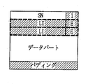
図4は、本発明の望ましい実施形態によるRLC PDUの構造を示す。
図4を参照すると、RLC PDUは、SNフィールド405と、Fフィールド410と、LIフィールド415と、Eフィールド420と、データフィールド425と、パディング430とを含む。LIフィールド415、Eフィールド420、パディング430は、場合によって含まないこともあるが、SNフィールド405、Fフィールド410、及びデータフィールド425は常に存在する。SNフィールド405、LIフィールド415、Eフィールド420、データフィールド425、及びパディング430は、従来のRLC PDUと同一であるため、その説明を省略する。
Fフィールド410は、LIフィールド415の存在有無を示し、すなわちRLC PDUのフレーミング方式を示す。また、Fフィールド410は、RLC SDUが連結/分割/パディングを経ることなく、RLC PDUにフレーミングされたか否かを示す。例えば、Fフィールド410が‘0’に設定されると、該当RLC PDUはLIフィールド415が存在せず、データフィールド425が一つの完全なRLC SDUと一致する。また、Fフィールド410が‘1’に設定されると、該当RLC PDUはLIフィールド415が存在し、データフィールド425のサイズが一つのRLC SDUと一致しない。したがって、LIフィールド415は、含まれるRLC SDUの開始或いは終了を示す。
FIG. 4 shows the structure of an RLC PDU according to a preferred embodiment of the present invention.
Referring to FIG. 4, the RLC PDU includes an
The
図5Aは、本発明の望ましい実施形態により、RLC SDUが分割/連結/パディングを経ることなく、RLC PDUに対応する場合にRLC PDUの構成を示す。
図5Aを参照すると、送信器(すなわち、送信器のRLC階層)は、一つの完全なRLC SDUを分割/連結/パディングせずに、一つのRLC PDUにフレーミングが可能である場合に、Fフィールドを‘0’に設定し、RLC PDUのデータフィールドに完全なRLC SDUを挿入する。
受信器(すなわち、受信器のRLC階層)は、受信されたRLC PDUのFフィールドが‘0’であると、Fフィールド以後からデータフィールドとして認知し、RLC PDUからデータフィールドを抽出して一つのRLC SDUとして上位階層に伝送する。
FIG. 5A illustrates a configuration of an RLC PDU when the RLC SDU corresponds to the RLC PDU without undergoing division / concatenation / padding according to a preferred embodiment of the present invention.
Referring to FIG. 5A, the transmitter (ie, the transmitter's RLC layer) can perform the F field when framing into one RLC PDU without splitting / concatenating / padding one complete RLC SDU. Is set to '0' and a complete RLC SDU is inserted into the data field of the RLC PDU.
If the F field of the received RLC PDU is '0', the receiver (that is, the RLC layer of the receiver) recognizes the data field from the F field onward and extracts one data field from the RLC PDU. It is transmitted to the upper layer as RLC SDU.
図5Bは、本発明の望ましい実施形態により、RLCが分割/連結/パディングを通じてRLC PDUにフレーミングされる場合に、RLC PDUの構造を示す。
図5Bを参照すると、送信器はRLCをフレーミングするために分割/連結/パディングを遂行することが必要である場合に、Fフィールドを‘1’に設定し、分割/連結/パディングに必要なLIフィールドとパディングを含んでRLC PUDを構成する。
受信器は、受信されたRLC PDUのFフィールドが‘1’であると、Fフィールド以後のバイトがLIフィールドとEフィールドであると判定し、LIフィールドの値によりRLC PDUのデータフィールドを一つ或いはそれ以上のRLC SDUに再構成する。
既存の第1のEフィールドをFフィールドとして用いるためには、下記のような問題点を解決すべきである。
通常、RLC PDUがRLC SDUのセグメント(segment)であり、RLC PDUにRLC SDUの開始も終了も含まない場合に、RLC PDUにはLIフィールドが存在しなかった。
図5Aでは、RLC SDUが分割/連結/パディングを経ることなく、一つのRLC PDUにフレーミングされる場合に、LIフィールドを使用しない。RLC PDUが一つの完全なRLC SDUを含まず、かつRLC SDUの開始又は終了を含まないことを示す必要がある。
FIG. 5B illustrates a structure of the RLC PDU when the RLC is framed into the RLC PDU through division / concatenation / padding according to a preferred embodiment of the present invention.
Referring to FIG. 5B, when the transmitter needs to perform division / concatenation / padding for framing the RLC, the F field is set to '1', and the LI necessary for the division / concatenation / padding is set. An RLC PUD is configured including fields and padding.
If the F field of the received RLC PDU is '1', the receiver determines that the bytes after the F field are the LI field and the E field, and determines one data field of the RLC PDU according to the value of the LI field. Or reconfigure to more RLC SDUs.
In order to use the existing first E field as the F field, the following problems should be solved.
Usually, when the RLC PDU is a segment of the RLC SDU and the RLC PDU does not include the start or end of the RLC SDU, the LI field is not present in the RLC PDU.
In FIG. 5A, the LI field is not used when the RLC SDU is framed into one RLC PDU without undergoing division / concatenation / padding. It needs to be shown that the RLC PDU does not contain one complete RLC SDU and does not contain the start or end of the RLC SDU.
図6Aは、従来のRLCフレーミング技術により、一つのRLC SDUが複数のRLC PDUに分割される状況を示す。
図6Aを参照すると、RLC SDU605がSN‘x’,‘x+1’,‘x+2’である3個のRLC PDU610,615,620に分割される。すると、第1のRLC PDU610には、予め定められたLI値‘1111 100’が挿入され、RLC PDU610のデータフィールドの第1のバイトがRLC SDU605の最初のバイトに対応することを示す。
第2のRLC PDU615には、RLC SDU605の開始と終了が含まれないため、第1のEフィールドが‘0’に設定され、LIフィールドは挿入されない。第3のRLC PDU620に、RLC SDU605の終了RLC PDU620のデータフィールドの34番目のバイトまでに該当することを示すために、例えばLI値‘0100 010’を挿入する。
RLC SDUの開始や終了を含まないRLC PDU615にLIフィールドを挿入しないと、受信器は、RLC PDU615のデータフィールドに含まれたセグメントが、一つの完全なRLC SDUを構成するか、或いは以前及び以後のRLC PDUのセグメントと結合して一つのRLC SDUを構成するか判定できない。したがって、後述する本発明の望ましい実施形態では、RLC SDUの開始や終了が含まれないRLC PDU(以下、“中間(intermediate)PDU'とする)を示すために、予め定められたLIの新たな値を定義する。例えば‘1111 110’を予め定められたLIの新たな値として定義する。予め定められたLIの新たな値が挿入されたRLC PDUは、中間RLC PDUとして認識される。ここで、中間RLC PDUのデータフィールドは、RLC SDUの開始と終了との間のRLC SDUセグメントを含む。
FIG. 6A illustrates a situation where one RLC SDU is divided into a plurality of RLC PDUs according to the conventional RLC framing technique.
Referring to FIG. 6A, the
Since the second RLC PDU 615 does not include the start and end of the
If the LI field is not inserted into the RLC PDU 615 that does not include the start or end of the RLC SDU, the receiver may make the segment included in the data field of the RLC PDU 615 form one complete RLC SDU or before and after. It is not possible to determine whether one RLC SDU is formed by combining with a segment of another RLC PDU. Therefore, in the preferred embodiment of the present invention described below, a new LI is newly defined to indicate an RLC PDU that does not include the start or end of the RLC SDU (hereinafter referred to as “intermediate PDU”). For example, '1111 110' is defined as a new value of a predetermined LI, and an RLC PDU in which a new value of a predetermined LI is inserted is recognized as an intermediate RLC PDU. Thus, the data field of the intermediate RLC PDU includes an RLC SDU segment between the start and end of the RLC SDU.
図6Bは、本発明の望ましい実施形態により、予め定められたLIを用いて一つのRLC SDUを複数のRLC PDUに分割する状況を示す。
図6Bを参照すると、一つのRLC SDU625がSN‘x’,‘x+1’,‘x+2’である3個のRLC PDU630,635,640に分割される。すると、第1のRLC PDU630にはFフィールドが‘1’に設定され、予め定められたLI値‘1111 100’が第1のRLC PDU630に挿入され、このRLC PDU630のデータフィールドの第1のバイトがRLC SDU625の第1のバイトに対応することを示す。第2のRLC PDU635にはRLC SDU625の開始も終了も含まれずに中間部分のみを含んでいるため、Fフィールドが‘0’に設定され、予め定められたLI値‘1111 110’が第2のRLC PDU635に挿入されて前記RLC PDU635が中間RLC PDUであることを示す。
第3のRLC PDU640には、RLC SDU625の終了、例えばデータフィールドの35番目のバイトまでであることを示すLI値‘0100 011’が含まれる。
FIG. 6B illustrates a situation in which one RLC SDU is divided into a plurality of RLC PDUs using a predetermined LI according to a preferred embodiment of the present invention.
Referring to FIG. 6B, one
The
以下、本発明の望ましい実施形態による動作及び装置の構成を説明する。下記で、RLC階層で遂行可能な分割/連結/パディングの中で連結の場合に、本発明の主な要旨から外れるため、その動作及び構成に関する説明を省略する。万一、連結が使用される場合に、第1のEフィールド(すなわち、Fフィールド)が‘1’である場合に少なくとも一つのLIフィールドが存在できることは自明である。 Hereinafter, operations and apparatus configurations according to preferred embodiments of the present invention will be described. In the following, in the case of concatenation among the division / concatenation / padding that can be performed in the RLC layer, since it departs from the main gist of the present invention, the description of the operation and configuration is omitted. If concatenation is used, it is obvious that there can be at least one LI field when the first E field (ie, F field) is '1'.
図7は、本発明の望ましい実施形態による送信器のRLC動作を示す。
図7を参照すると、ステップS705で、上位階層から少なくとも一つのRLC SDUを受信すると、ステップS710で送信器のRLC階層は受信された少なくとも一つのRLC SDUのサイズと個数を下位階層に知らせる。下位階層は、MAC階層になることができる。RLC SDUを伝送するときにLI=‘0000 000’を伝送すべきである場合に、送信器のRLC階層はRLC SDUのサイズに1バイトを加算した値を下位階層に知らせる。
ステップS715で、送信器のRLC階層は、下位階層が次の伝送区間で伝送されるRLC PDUのサイズと個数を通報するまで待機する。下位階層は、受信されたRLC SDU情報と次の伝送区間の無線チャンネル状況に基づいて最も効率的なRLC PDUのサイズを決定する。これは送信側RLC階層に通報される。
FIG. 7 illustrates RLC operation of a transmitter according to a preferred embodiment of the present invention.
Referring to FIG. 7, when at least one RLC SDU is received from the upper layer in step S705, the RLC layer of the transmitter notifies the lower layer of the size and number of the received at least one RLC SDU in step S710. The lower layer can be a MAC layer. When LI = '0000 000' should be transmitted when transmitting the RLC SDU, the RLC layer of the transmitter notifies the lower layer of the value obtained by adding 1 byte to the size of the RLC SDU.
In step S715, the transmitter RLC layer waits until the lower layer reports the size and number of RLC PDUs transmitted in the next transmission interval. The lower layer determines the most efficient RLC PDU size based on the received RLC SDU information and the radio channel status of the next transmission interval. This is reported to the transmitting RLC layer.
ステップS720で、RLC階層は、下位階層が通報したRLC PDUのサイズがRLC SDUのサイズと一致するか、或いは以前のRLC PDUに以前のRLC SDUの最後のバイトを示すLIフィールドが含まれたかによって、現在のRLC PDUを通じてLI=‘0000 000’を伝送する必要があるか否かを判定する。その結果、RLC PDUのサイズがRLC SDUのサイズと一致し、LI=‘0000 000’を伝送する必要がないと、RLC階層はステップS725に進行する。ここで、RLC PDUのサイズがRLC SDUのサイズと一致し、或いはRLC SDUのサイズにRLCヘッダーの最小サイズを加算した値が、RLC PDUのサイズと一致し、或いはRLC PDUのサイズより大きくないながらほぼ類似することを意味する。言い換えれば、RLC PDUの第1のEフィールド(すなわち、Fフィールド)を‘0’に設定し、RLC SDUの開始と終了を示すLIフィールドを使用しないときに、完全なRLC SDUはRLC PDUのデータフィールドに挿入して伝送することができる。
参考として、LI=‘00000 000’は、以前のRLC PDUの終了が以前のRLC SDUの終了に正確に一致するときに、終了を示すLIフィールドは、以前のRLC PDUに含めない場合に使用される。
ステップS725で、送信器のRLC階層は、現在のRLC PDUのFフィールドを‘0’に設定し、ステップS730でいずれのLIフィールドも含めずに完全なRLC SDUをRLC PDUのデータフィールドに挿入した後に、ステップS735で、RLC PDUを下位階層に伝送して受信器のRLC階層に伝送する。
In step S720, the RLC layer determines whether the size of the RLC PDU reported by the lower layer matches the size of the RLC SDU, or whether the previous RLC PDU includes an LI field indicating the last byte of the previous RLC SDU. It is determined whether LI = '0000 000' needs to be transmitted through the current RLC PDU. As a result, if the size of the RLC PDU matches the size of the RLC SDU and it is not necessary to transmit LI = '0000 000', the RLC layer proceeds to step S725. Here, the size of the RLC PDU matches the size of the RLC SDU, or the value obtained by adding the minimum size of the RLC header to the size of the RLC SDU matches the size of the RLC PDU or is not larger than the size of the RLC PDU. It means almost similar. In other words, when the first E field (ie, F field) of the RLC PDU is set to '0' and the LI field indicating the start and end of the RLC SDU is not used, the complete RLC SDU is data in the RLC PDU. It can be inserted into the field and transmitted.
For reference, LI = '00000 000' is used when the end of the previous RLC PDU exactly matches the end of the previous RLC SDU and the end LI field is not included in the previous RLC PDU. The
In step S725, the RLC layer of the transmitter sets the F field of the current RLC PDU to '0', and inserts the complete RLC SDU into the data field of the RLC PDU without including any LI field in step S730. Later, in step S735, the RLC PDU is transmitted to the lower layer and transmitted to the RLC layer of the receiver.
一方、ステップS720の結果、RLC PDUのサイズがRLC SDUのサイズと一致せず、或いはLI=‘0000 000’の伝送が必要である場合に、ステップS740で送信器のRLC階層は現在のRLC PDUのFビットを‘1’に設定する。ステップS745で、RLC階層は、上記のRLC SDUから生成された中間RLC PDUであるか否かを判定する。中間RLC PDUが存在すれば、中間RLC PDUのLIフィールドのみが予め定められた新たなLI値‘1111 110’に設定される。予め定められたLIの新たな値は、システム或いは設計者によって設定される。ステップS750で、送信器のRLC階層は、RLC PDUを下位階層に伝送して受信器のRLC階層に伝送されるようにする。 On the other hand, if the size of the RLC PDU does not match the size of the RLC SDU or the transmission of LI = '0000 000' is necessary as a result of step S720, the transmitter's RLC layer becomes the current RLC PDU in step S740. Set the F bit to '1'. In step S745, the RLC layer determines whether it is an intermediate RLC PDU generated from the RLC SDU. If there is an intermediate RLC PDU, only the LI field of the intermediate RLC PDU is set to a new predetermined LI value '1111 110'. A new value for the predetermined LI is set by the system or the designer. In step S750, the RLC layer of the transmitter transmits the RLC PDU to the lower layer to be transmitted to the RLC layer of the receiver.
図8は、本発明の望ましい実施形態による受信器のRLC動作を示すフローチャートである。
図8を参照すると、ステップS805で、受信器のRLC階層は、下位階層からRLC PDUを受信する。ステップS810で、RLC階層は、RLC PDUの第1のEフィールド(すなわち、Fフィールド)を検査する。Fフィールドが‘1’であると、ステップS820に進行し、Fフィールドが‘0’であると、ステップS815に進行する。
Fフィールドが‘0’である場合に、これは、RLC PDUに分割/連結/パディングが適用されないことを意味する。したがって、ステップS815で、受信器のRLC階層は、RLC PDUからRLCヘッダー(すなわち、SNフィールドとFフィールド)を除き、残りのデータフィールドを一つの完全なRLC SDUで再構成する。すなわち、RLC PDUのデータフィールドは一つの完全なRLC SDUで構成される。ステップS850で、上記のRLC階層は、RLC SDUを上位階層に伝送する。
FIG. 8 is a flowchart illustrating an RLC operation of a receiver according to an exemplary embodiment of the present invention.
Referring to FIG. 8, in step S805, the RLC layer of the receiver receives an RLC PDU from a lower layer. In step S810, the RLC layer checks the first E field (ie, F field) of the RLC PDU. If the F field is “1”, the process proceeds to step S820. If the F field is “0”, the process proceeds to step S815.
If the F field is '0', this means that no division / concatenation / padding is applied to the RLC PDU. Accordingly, in step S815, the RLC layer of the receiver removes the RLC header (ie, SN field and F field) from the RLC PDU and reconstructs the remaining data fields with one complete RLC SDU. That is, the data field of RLC PDU is composed of one complete RLC SDU. In step S850, the RLC layer transmits the RLC SDU to the upper layer.
Fフィールドが‘1’である場合に、これは、RLC PDUに分割/連結/パディングが適用され、少なくとも一つのLIフィールドが存在することを意味する。ステップS820で、受信器のRLC階層は、RLC PDUを該当SNにより受信バッファに貯蔵する。
ステップS825で受信器のRLC階層は、RLC PDUの第1のLIフィールドが新たに定義されたLI値‘1111 110’であるか否かを判定する。LI=‘1111 110’であると、RLC階層は、ステップS830に進行する。そうでないと、ステップS835に進行する。ステップS830で、受信器のRLC階層は、RLC PDUがRLC SDUの中間セグメントを含んでいると判定し、ステップS835に進行する。ステップS835で、受信器のRLC階層は、受信バッファに貯蔵されているRLC PDUのSNとLIフィールドを検査し、RLC SDUの再組み立て、すなわち復元が可能であるか否かを判定する。連続的なSNを有する貯蔵されたRLC PDUの中でn個のRLC PDU(nは1より大きい整数)が下記の条件を満足する場合に、RLC SDUの再組み立てが可能になる。
If the F field is '1', this means that division / concatenation / padding is applied to the RLC PDU and there is at least one LI field. In step S820, the RLC layer of the receiver stores the RLC PDU in the reception buffer by the corresponding SN.
In step S825, the RLC layer of the receiver determines whether the first LI field of the RLC PDU is a newly defined LI value '1111 110'. If LI = '1111 110', the RLC layer proceeds to step S830. Otherwise, the process proceeds to step S835. In step S830, the RLC layer of the receiver determines that the RLC PDU includes an intermediate segment of the RLC SDU, and proceeds to step S835. In step S835, the RLC layer of the receiver examines the SN and LI fields of the RLC PDU stored in the reception buffer to determine whether the RLC SDU can be reassembled, that is, restored. When n RLC PDUs (where n is an integer greater than 1) among stored RLC PDUs having consecutive SNs satisfy the following conditions, reassembly of the RLC SDUs becomes possible.
条件1:n個のRLC PDUのうち、第1のRLC PDUの最後のLIフィールドは新たなRLC SDUが始まることを示す。
条件2:第2のRLC PDUから(n-1)番目のRLC PDUは各々一つのLIフィールドのみを含み、各LIフィールドが‘1111 110’に設定される。
条件3:最後のn番目のRLC PDUの第1のLIフィールドがRLC SCUの最後のバイトの位置を示す。
Condition 1: Among the n RLC PDUs, the last LI field of the first RLC PDU indicates that a new RLC SDU starts.
Condition 2: The (n-1) th RLC PDU from the second RLC PDU includes only one LI field, and each LI field is set to '1111 110'.
Condition 3: The first LI field of the last nth RLC PDU indicates the position of the last byte of the RLC SCU.
貯蔵されているRLC PDUの中で、これら条件を満足するn個のRLC PDUがある場合に、受信器のRLC階層はステップS840に進行し、そうでない場合にはステップS845に進行して新たなRLC PDUが受信されるまで待機する。
ステップS840で、RLC階層は上記の条件を満たすRLC PDUのSNとLIフィールドを参照してRLC SDUを再構成し、ステップS850で再構成したRLC SDUを上位階層に伝送する。
If there are n RLC PDUs satisfying these conditions among the stored RLC PDUs, the RLC layer of the receiver proceeds to step S840; otherwise, the process proceeds to step S845. Wait until RLC PDU is received.
In step S840, the RLC layer refers to the SN and LI fields of the RLC PDU that satisfies the above conditions, reconfigures the RLC SDU, and transmits the reconfigured RLC SDU to the upper layer in step S850.
図9は、本発明の望ましい実施形態による送信器のRLC階層として動作する送信器を示すブロック構成図である。
図9を参照すると、送信器は、伝送バッファ905と、RLCヘッダー挿入部910と、LI挿入部915と、送信部920と、F設定部925と、PDUサイズ制御部930とを含む。
伝送バッファ905は、上位階層から受信された少なくとも一つのRLC SDUを貯蔵し、貯蔵された少なくとも一つのRLC SDUのサイズと個数をPDUサイズ制御部930に通報する。このPDUサイズ制御部930は、通報された情報及び追加的な情報を参照して最も高い伝送効率を保証するRLC PDUサイズを決定して伝送バッファ905に通報する。
伝送バッファ905は、貯蔵された少なくとも一つのRLC SDUを通報されたRLC PDUサイズに合わせて再構成してRLCヘッダー挿入部910に提供する。いずれか一つのRLC SDUのサイズがRLC PDUのデータフィールドと同一のサイズを有すると、伝送バッファ905は、RLC SDUを加工せずにその通りRLCヘッダー挿入部910に伝送する。Fフィールド設定部925は、RLC SDUのサイズがRLC PDUのデータフィールドと同一のサイズを有する場合に、RLC PDUのFフィールドを‘0’に設定するようにRLCヘッダー挿入部910を制御する。RLCヘッダー挿入部910は、伝送バッファ905から受信されたデータにF設定部925の制御によるFフィールドとSNを挿入する。LI挿入部915は、Fフィールドが‘0’に設定されると、RLCヘッダー挿入部910から受信されたデータにLIフィールドを挿入せず、その反面、Fフィールドが‘1’に設定されている場合に、LI挿入部915はLIフィールドを挿入する。送信部920は、上記の手順によって生成されたRLC PCUを無線チャンネルを通じて伝送する。
FIG. 9 is a block diagram illustrating a transmitter operating as an RLC layer of a transmitter according to an exemplary embodiment of the present invention.
Referring to FIG. 9, the transmitter includes a
The
The
図10は、本発明の望ましい実施形態による受信器のRLC階層として動作する受信器を示すブロック構成図である。
図10を参照すると、受信器は、受信部1020と、受信バッファ1015とRLCヘッダー及びLI除去部1010と、再組み立て部1005、及び再組み立て制御部1025とを含む。
受信部1020は、下位階層から受信されたRLC PDUを受信バッファ1015に提供する。受信バッファ1015は、RLC PDUが再組み立てされるまで貯蔵する。この再組み立て制御部1025は、受信バッファ1015に貯蔵されているRLC PDUのFフィールドとSNとLIを解析し、再組み立てが可能であるか否かを判定し、再組み立てが可能な少なくとも一つのRLC PDUをRLCヘッダー及びLI除去部1010に提供されるように受信バッファ1015を制御する。
RLCヘッダー及びLI除去部1010は、上記のRLC PDUからRLCヘッダーとLIフィールドを除去する。このとき、Fフィールドが‘0’に設定されたRLC PDUに対しては除去するLIフィールドが存在しないため、RLCヘッダーのみを除去する。
再組み立て部1005は、RLCヘッダーとLIフィールドが除去された一つのRLC PDUを用いてRLC SDUを再組み立てして上位階層に伝送する。このとき、再組み立て部1005は、Fフィールドが‘0’に設定されたRLC PDUのデータフィールドから抽出されたデータのみで一つの完全なRLC SDUを構成する。また、再組み立て部1005は、Fフィールドが‘1’に設定され、予め定められた値である‘1111 110’に設定された唯一のLIフィールドを有するRLC PDUのデータフィールドから抽出された中間SDUセグメントを、以前及び以後のRLC PDUから抽出されたセグメントと結合して一つのRLC SDUで構成する。
FIG. 10 is a block diagram illustrating a receiver that operates as an RLC layer of a receiver according to an exemplary embodiment of the present invention.
Referring to FIG. 10, the receiver includes a
The
The RLC header and
The
以上、本発明の詳細な説明においては具体的な実施形態に関して説明したが、特許請求の範囲を外れない限り、形式や細部についての様々な変更が可能であることは、当該技術分野における通常の知識を持つ者には明らかである。したがって、本発明の範囲は、前述の実施形態に限定されるものではなく、特許請求の範囲の記載及びこれと均等なものに基づいて定められるべきである。 Although the present invention has been described above with reference to specific embodiments, it is understood that various changes in form and details may be made without departing from the scope of the claims. It is clear to those who have knowledge. Therefore, the scope of the present invention should not be limited to the above-described embodiments, but should be determined based on the description of the scope of claims and equivalents thereof.
905 伝送バッファ
910 RLCヘッダー挿入部
915 LI挿入部
920 送信部
925 F設定部
930 PDUサイズ制御部
1005 再組み立て部
1010 RLCヘッダー及びLI除去部
1015 受信バッファ
1020 受信部
1025 再組み立て制御部
905
Claims (18)
上位階層からサービスデータユニット(SDU)を受信し、前記SDUが一つのプロトコルデータユニット(PDU)に含まれるか否かを判定する段階と、
前記SDUが一つのPDUに含まれない場合に、前記SDUを伝送可能なPDUのサイズにより複数のセグメントに分割する段階と、
一連番号(SN)フィールドと、LIフィールドが存在することを示す少なくとも一つの1ビットフィールドと、前記LIフィールドとをヘッダー内に有し、前記セグメントをデータフィールド内に有する複数のPDUを構成する段階と、ここで前記SDUの中間セグメントをデータフィールド内に含むPDUの前記LIフィールドは、前記中間セグメントが存在することを示す値に設定され、
前記PDUを受信器に伝送する段階と、
を有することを特徴とするデータ送信方法。 A method for transmitting data using a predetermined length indicator (LI) in a mobile communication system, comprising:
Receiving a service data unit (SDU) from an upper layer and determining whether the SDU is included in one protocol data unit (PDU);
When the SDU is not included in one PDU, dividing the SDU into a plurality of segments according to the size of a PDU that can be transmitted;
Configuring a plurality of PDUs having a sequence number (SN) field, at least one 1-bit field indicating the presence of an LI field, and the LI field in a header and the segment in a data field Where the LI field of the PDU including the intermediate segment of the SDU in the data field is set to a value indicating that the intermediate segment exists,
Transmitting the PDU to a receiver;
A data transmission method characterized by comprising:
前記SDUのサイズと無線チャンネル状況により決定され、次の伝送区間で使用可能な前記SNフィールドと前記1ビットフィールドを除いたPDUサイズが前記SDUのサイズと一致すると、前記SDUが一つのPDUに含まれると判定することを特徴とする請求項1記載のデータ送信方法。 The step of determining includes
The SDU is included in one PDU when the PDU size determined by the SDU size and the radio channel condition and excluding the SN field and the 1-bit field usable in the next transmission section matches the SDU size. The data transmission method according to claim 1, wherein it is determined that the data is transmitted.
送信器からプロトコルデータユニット(PDU)を受信し、前記PDUのヘッダーからSNフィールドと次のLIフィールドが存在するか否かを示す1ビットフィールドを検出する段階と、
前記1ビットフィールドが前記LIフィールドが存在することを示す場合に、前記PDUのヘッダーから次の前記LIフィールドを検出し、前記LIフィールドが前記PDUのデータフィールド内にサービスデータユニット(SDU)の中間セグメントが含まれることを示す値に設定されているか否かを判定する段階と、
前記LIフィールドが前記値に設定される場合に、前記PDUを以前のセグメント及び以後のセグメントと組み合わせることができるまで貯蔵する段階と、
前記PDUのデータフィールドからの中間セグメントを、少なくとも一つの以前のPDUのデータフィールドから抽出された少なくとも一つの以前のセグメント及び少なくとも一つの以後のPDUのデータフィールドから抽出された少なくとも一つの以後のセグメントと結合して前記SDUを構成する段階と、
を有することを特徴とするデータ受信方法。 A method for receiving data using a predetermined length indicator (LI) in a mobile communication system, comprising:
Receiving a protocol data unit (PDU) from a transmitter and detecting from the header of the PDU a 1-bit field indicating whether an SN field and a next LI field are present;
If the 1-bit field indicates that the LI field is present, the next LI field is detected from the header of the PDU, and the LI field is in the middle of the service data unit (SDU) in the data field of the PDU. Determining whether it is set to a value indicating that a segment is included;
Storing the PDU until it can be combined with previous and subsequent segments when the LI field is set to the value;
An intermediate segment from the PDU data field is extracted from at least one previous segment extracted from at least one previous PDU data field and at least one subsequent segment extracted from at least one subsequent PDU data field. Combining the SDU to configure the SDU;
A data receiving method characterized by comprising:
前記PDUのうち最初のPDUが前記SDUの最初のセグメントを含むことを示すLIフィールドを含み、前記PDUの中で少なくとも一つの中間PDUは前記値に設定されたLIフィールドを含み、前記PDUのうち最後のPDUの第1のLIフィールドが前記SDUの最後のバイトの位置を示す場合に、前記受信バッファに貯蔵された一組のPDUのデータフィールドから抽出されたセグメントを結合して前記SDUを構成することを特徴とする請求項8記載のデータ受信方法。 The step of configuring comprises
A LI field indicating that a first PDU of the PDU includes a first segment of the SDU, wherein at least one intermediate PDU includes a LI field set to the value; When the first LI field of the last PDU indicates the position of the last byte of the SDU, the SDU is configured by combining segments extracted from the data field of a set of PDUs stored in the reception buffer. The data receiving method according to claim 8, wherein:
上位階層からサービスデータユニット(SDU)を受信し、前記SDUが一つのプロトコルデータユニット(PDU)に含まれるか否かを判定し、前記SDUを伝送可能なPDUサイズによって少なくとも一つのセグメントに再構成するための伝送バッファと、
SNフィールドと1ビットフィールドをヘッダーに含み、前記少なくとも一つのセグメントをデータフィールド内に有する少なくとも一つのPDUを構成するヘッダー挿入部と、
前記少なくとも一つのPDUの1ビットフィールドを、以後のLIフィールドの存在有無のうち少なくとも一つを示す値に設定する1ビットフィールド設定部と、
前記SDUが一つのPDUに含まれない場合に、前記少なくとも一つのPDUの前記1ビットフィールド以後にLIフィールドを挿入し、前記SDUの中間セグメントをデータフィールド内に含むPDUのLIフィールドを、前記中間セグメントを含むことを示す値に設定するLI挿入部と、
前記LI挿入部から受信される少なくとも一つのPDUを受信部に伝送する送信部と、
を含むことを特徴をするデータ送信装置。 An apparatus for transmitting data using a predetermined length indicator (LI) in a mobile communication system,
A service data unit (SDU) is received from an upper layer, it is determined whether or not the SDU is included in one protocol data unit (PDU), and the SDU is reconfigured into at least one segment according to a PDU size that can be transmitted. A transmission buffer for
A header insertion unit that includes an SN field and a 1-bit field in a header and constitutes at least one PDU having the at least one segment in a data field;
A 1-bit field setting unit that sets a 1-bit field of the at least one PDU to a value indicating at least one of the presence or absence of a subsequent LI field;
When the SDU is not included in one PDU, an LI field is inserted after the 1-bit field of the at least one PDU, and an LI field of the PDU including an intermediate segment of the SDU in a data field An LI insertion part set to a value indicating that the segment is included;
A transmission unit for transmitting at least one PDU received from the LI insertion unit to the reception unit;
A data transmission device characterized by comprising:
送信部からプロトコルデータユニット(PDU)を受信して貯蔵する受信バッファと、
前記受信したPDUのヘッダーから、SNフィールドと、次のLIフィールドの存在有無のうち少なくとも一つを示す1ビットフィールドを検出し、前記1ビットフィールドが前記LIフィールドが存在することを示す場合に前記LIフィールドを解析し、前記LIフィールドが前記PDUのデータフィールド内にサービスデータユニット(SDU)の中間セグメントが含まれることを示す値に設定されている場合に、前記PDUが以前のセグメント及び以後のセグメントと組み立てができるまで貯蔵されるように前記受信バッファを制御する再組み立て制御部と、
前記1ビットフィールドが前記LIフィールドが存在することを示す場合に、前記SNフィールド、前記1ビットフィールド、及び前記LIフィールドを除去して前記PDUのデータフィールドから中間セグメントを抽出するヘッダー及びLI除去部と、
前記ヘッダー及びLI除去部から前記中間セグメントを受信し、前記中間セグメントを、少なくとも一つの以前のPDUのデータフィールドから抽出された少なくとも一つの以前のセグメント及び少なくとも一つの以後のPDUのデータフィールドから抽出された少なくとも一つの以後のセグメントと結合して前記SDUを構成する再組み立て部と、
を含むことを特徴とするデータ受信装置。 An apparatus for receiving data using a predetermined length indicator (LI) in a mobile communication system, comprising:
A reception buffer for receiving and storing protocol data units (PDUs) from the transmission unit;
When a 1-bit field indicating at least one of the SN field and the presence / absence of the next LI field is detected from the header of the received PDU, and the 1-bit field indicates that the LI field is present, When the LI field is parsed and the LI field is set to a value indicating that an intermediate segment of a service data unit (SDU) is included in the data field of the PDU, the PDU is A reassembly controller that controls the receive buffer to be stored until assembled with a segment;
A header and LI removal unit that removes the SN field, the 1-bit field, and the LI field and extracts an intermediate segment from the data field of the PDU when the 1-bit field indicates that the LI field exists When,
Receiving the intermediate segment from the header and LI remover, and extracting the intermediate segment from at least one previous segment and at least one subsequent PDU data field extracted from at least one previous PDU data field; A reassembly unit combined with at least one subsequent segment formed to constitute the SDU;
A data receiving apparatus comprising:
前記PDUのうち最初のPDUが前記SDUの最初のセグメントを含むことを示すLIフィールドを含み、前記PDUの中で少なくとも一つの中間PDUは前記値に設定されたLIフィールドを含み、前記PDUのうち最後のPDUの第1のLIフィールドが前記SDUの最後のバイトの位置を示す場合に、前記受信バッファに貯蔵された一組のPDUのデータフィールドから抽出されたセグメントを結合して前記SDUを構成することを特徴とする請求項17記載のデータ受信装置。 The reassembly part is
A LI field indicating that a first PDU of the PDU includes a first segment of the SDU, wherein at least one intermediate PDU includes a LI field set to the value; When the first LI field of the last PDU indicates the position of the last byte of the SDU, the SDU is configured by combining segments extracted from the data field of a set of PDUs stored in the reception buffer. 18. The data receiving device according to claim 17, wherein
Applications Claiming Priority (2)
| Application Number | Priority Date | Filing Date | Title |
|---|---|---|---|
| KR20050037774A KR100913900B1 (en) | 2005-05-04 | 2005-05-04 | A method and apparatus for transmitting/receiving packet data using predefined length indicator in mobile communication system |
| PCT/KR2006/001699 WO2006118435A1 (en) | 2005-05-04 | 2006-05-04 | Method and apparatus for transmitting/receiving packet data using pre-defined length indicator in a mobile communication system |
Publications (2)
| Publication Number | Publication Date |
|---|---|
| JP2008538480A true JP2008538480A (en) | 2008-10-23 |
| JP4642898B2 JP4642898B2 (en) | 2011-03-02 |
Family
ID=36838690
Family Applications (1)
| Application Number | Title | Priority Date | Filing Date |
|---|---|---|---|
| JP2008507565A Active JP4642898B2 (en) | 2005-05-04 | 2006-05-04 | Method and apparatus for transmitting and receiving packet data using a preset length indicator in a mobile communication system |
Country Status (17)
| Country | Link |
|---|---|
| US (1) | US7675941B2 (en) |
| EP (1) | EP1720322B1 (en) |
| JP (1) | JP4642898B2 (en) |
| KR (1) | KR100913900B1 (en) |
| CN (1) | CN101171806B (en) |
| AT (1) | ATE546903T1 (en) |
| AU (1) | AU2006241621B2 (en) |
| BR (1) | BRPI0610898A2 (en) |
| CA (1) | CA2602815C (en) |
| CY (1) | CY1112782T1 (en) |
| DK (1) | DK1720322T3 (en) |
| ES (1) | ES2382341T3 (en) |
| PL (1) | PL1720322T3 (en) |
| PT (1) | PT1720322E (en) |
| RU (1) | RU2346402C1 (en) |
| SI (1) | SI1720322T1 (en) |
| WO (1) | WO2006118435A1 (en) |
Cited By (6)
| Publication number | Priority date | Publication date | Assignee | Title |
|---|---|---|---|---|
| JP2012531131A (en) * | 2009-06-22 | 2012-12-06 | アルカテル−ルーセント | Method and apparatus for controlling downlink data synchronization of eMBMS transmission |
| US8681670B2 (en) | 2008-08-08 | 2014-03-25 | Fujitsu Limited | Apparatus and method for multiplexing data of a layer into data transmission unit of another layer |
| JP2015167410A (en) * | 2007-02-02 | 2015-09-24 | インターデイジタル テクノロジー コーポレーション | Method and apparatus for versatile mac multiplexing in evolved hspa |
| JP2019516319A (en) * | 2016-04-27 | 2019-06-13 | エルジー エレクトロニクス インコーポレイティド | Method and apparatus for receiving data units |
| US10701588B2 (en) | 2015-12-23 | 2020-06-30 | Nokia Solutions And Networks Oy | Methods, apparatuses and computer program product for PDU formatting according to SDU segmentation |
| JP2020520153A (en) * | 2017-05-05 | 2020-07-02 | 華為技術有限公司Huawei Technologies Co.,Ltd. | Data transmission method, apparatus, system, and device |
Families Citing this family (123)
| Publication number | Priority date | Publication date | Assignee | Title |
|---|---|---|---|---|
| US7193609B2 (en) | 2002-03-19 | 2007-03-20 | America Online, Inc. | Constraining display motion in display navigation |
| TWI307589B (en) * | 2005-05-18 | 2009-03-11 | Innovative Sonic Ltd | Method and apparatus of data segmentation in a mobile communications system |
| JP4923849B2 (en) | 2006-08-21 | 2012-04-25 | 富士通株式会社 | Wireless receiver |
| KR101387500B1 (en) | 2006-08-22 | 2014-04-21 | 엘지전자 주식회사 | Method of transmitting and receiving control information in wireless communicaiton system |
| KR101265643B1 (en) * | 2006-08-22 | 2013-05-22 | 엘지전자 주식회사 | A mothod of executing handover and controlling thereof in mobile communication system |
| US8619685B2 (en) | 2006-10-02 | 2013-12-31 | Lg Electronics Inc. | Method for transmitting and receiving paging message in wireless communication system |
| JP4523072B2 (en) | 2006-10-30 | 2010-08-11 | エルジー エレクトロニクス インコーポレイティド | Redirection method for uplink connection |
| CN101175087A (en) * | 2006-10-30 | 2008-05-07 | 华硕电脑股份有限公司 | Method and apparatus for header setting in a wireless communications system |
| US8428013B2 (en) * | 2006-10-30 | 2013-04-23 | Lg Electronics Inc. | Method of performing random access in a wireless communcation system |
| WO2008054119A2 (en) * | 2006-10-30 | 2008-05-08 | Lg Electronics Inc. | Methods for transmitting access channel message and response message, and mobile communication terminals |
| KR100938754B1 (en) | 2006-10-30 | 2010-01-26 | 엘지전자 주식회사 | Data transmission method and data receiving method using discontinuous reception |
| WO2008053552A1 (en) * | 2006-11-01 | 2008-05-08 | Fujitsu Limited | Wireless communication apparatus and wireless communication method |
| US8797879B2 (en) | 2006-12-07 | 2014-08-05 | Lg Electronics Inc. | Method of transmitting and receiving status report in a mobile communication system |
| US9173223B2 (en) | 2006-12-07 | 2015-10-27 | Lg Electronics Inc. | Method of transferring data in a wireless communication system |
| TWI466518B (en) * | 2006-12-12 | 2014-12-21 | Interdigital Tech Corp | Method and apparatus for transmitting and receiving a packet via high speed downlink packet access |
| US20100046448A1 (en) * | 2006-12-15 | 2010-02-25 | Telefonak Tiebolaget Lm Ericsson ( | Single Bit Segmentation Indicator |
| TWI521927B (en) | 2007-01-09 | 2016-02-11 | 皇家飛利浦電子股份有限公司 | Wireless communication system |
| KR101211758B1 (en) | 2007-01-10 | 2012-12-12 | 엘지전자 주식회사 | Method for generating block data in wireless communication system |
| RU2414065C1 (en) | 2007-01-10 | 2011-03-10 | ЭлДжи ЭЛЕКТРОНИКС ИНК. | Method of constructing data format in mobile communication and terminal thereof |
| KR101461938B1 (en) | 2007-01-31 | 2014-11-14 | 엘지전자 주식회사 | Method for transmitting and receiving system information |
| US7817669B2 (en) | 2007-02-01 | 2010-10-19 | Interdigital Technology Corporation | Method and apparatus for supporting RLC re-segmentation |
| KR101326474B1 (en) * | 2007-02-06 | 2013-11-07 | 엘지전자 주식회사 | Method for transmitting data block in wireless communication system |
| US9071988B2 (en) * | 2007-03-15 | 2015-06-30 | Core Wireless Licensing S.A.R.L | Apparatus, computer program product, and methods for flexible data unit segmentation and arrangement |
| US8619752B2 (en) * | 2007-03-16 | 2013-12-31 | Qualcomm Incorporated | Method and apparatus for polling in a wireless communication system |
| KR101435832B1 (en) | 2007-03-19 | 2014-08-29 | 엘지전자 주식회사 | Method for processing radio protocol in mobile telecommunications system and transmitter of mobile telecommunications |
| CN101272519B (en) * | 2007-03-21 | 2012-09-19 | 上海贝尔股份有限公司 | Method, device and base station for generating protocol data unit |
| WO2008115025A1 (en) | 2007-03-22 | 2008-09-25 | Lg Electronics Inc. | Method of transmitting data block in wireless communication system |
| KR101023388B1 (en) | 2007-04-11 | 2011-03-18 | 삼성전자주식회사 | Method and apparatus for transmitting and receiving packet data unitin mobile communication system |
| KR101430756B1 (en) * | 2007-04-25 | 2014-08-14 | 삼성전자주식회사 | Method and Apparatus for Transmitting/Receiving Packet in Mobile Communication System |
| KR101386812B1 (en) | 2007-04-30 | 2014-04-29 | 엘지전자 주식회사 | Methods for transmitting or receiving data unit(s) using a header field existence indicator |
| EP2132910B1 (en) * | 2007-04-30 | 2016-01-06 | LG Electronics Inc. | Method of transmitting data in a wireless communication system |
| WO2008133481A1 (en) | 2007-04-30 | 2008-11-06 | Lg Electronics Inc. | Method for performing an authentication of entities during establishment of wireless call connection |
| KR101464748B1 (en) | 2007-04-30 | 2014-11-24 | 엘지전자 주식회사 | Method for triggering a measurement report of mobile terminal |
| KR101455999B1 (en) | 2007-04-30 | 2014-11-03 | 엘지전자 주식회사 | Methods of generating data blocks in wireless communication system |
| KR101469281B1 (en) | 2007-04-30 | 2014-12-04 | 엘지전자 주식회사 | Method for state transition of mobile terminal |
| WO2008133485A1 (en) * | 2007-04-30 | 2008-11-06 | Lg Electronics Inc. | Methods of generating data block in mobile communication system |
| KR101458641B1 (en) * | 2007-04-30 | 2014-11-05 | 엘지전자 주식회사 | Method of transmitting data in wireless communication system supporting multimedia broadcast/multicast service |
| US8358669B2 (en) * | 2007-05-01 | 2013-01-22 | Qualcomm Incorporated | Ciphering sequence number for an adjacent layer protocol in data packet communications |
| KR20080097338A (en) * | 2007-05-01 | 2008-11-05 | 엘지전자 주식회사 | Discontinuous data transmittion/reception method |
| KR100917205B1 (en) * | 2007-05-02 | 2009-09-15 | 엘지전자 주식회사 | Method of configuring a data block in wireless communication system |
| US20080273482A1 (en) * | 2007-05-02 | 2008-11-06 | Lg Electronics Inc. | Uplink access method for receiving a point-to-multipoint service |
| WO2008136598A1 (en) * | 2007-05-03 | 2008-11-13 | Lg Electronics Inc. | Method of data processing in a wireless communication system |
| GB2448933B (en) * | 2007-05-04 | 2009-11-25 | Nec Corp | Content synchronization for mobile communication network |
| US8331399B2 (en) * | 2007-05-07 | 2012-12-11 | Qualcomm Incorporated | Re-using sequence number by multiple protocols for wireless communication |
| KR101470638B1 (en) * | 2007-06-18 | 2014-12-08 | 엘지전자 주식회사 | Method for enhancing radio resource and informing status report in mobile telecommunications system and receiver of mobile telecommunications |
| KR101486352B1 (en) | 2007-06-18 | 2015-01-26 | 엘지전자 주식회사 | Method of controlling uplink synchronization state at a user equipment in a mobile communication system |
| HUE033683T2 (en) | 2007-06-18 | 2017-12-28 | Lg Electronics Inc | Method and user equipment for performing uplink synchronization in wireless communication system |
| KR101341515B1 (en) | 2007-06-18 | 2013-12-16 | 엘지전자 주식회사 | Method of updating repeatedly-transmitted information in wireless communicaiton system |
| US8463300B2 (en) * | 2007-06-18 | 2013-06-11 | Lg Electronics Inc. | Paging information transmission method for effective call setup |
| KR101526971B1 (en) | 2007-06-18 | 2015-06-11 | 엘지전자 주식회사 | Method for transmitting/receiving broadcast or multicast service and terminal thereof |
| WO2008156309A1 (en) * | 2007-06-18 | 2008-12-24 | Lg Electronics Inc. | Control channel reception method for receiving broadcast or multicast service |
| KR101470637B1 (en) * | 2007-06-18 | 2014-12-08 | 엘지전자 주식회사 | Method for enhancing radio resource and informing status report in mobile telecommunications system and receiver of mobile telecommunications |
| WO2008156346A2 (en) * | 2007-06-20 | 2008-12-24 | Lg Electronics Inc. | A method of transmitting data in mobile communication system |
| WO2008156314A2 (en) | 2007-06-20 | 2008-12-24 | Lg Electronics Inc. | Effective system information reception method |
| KR20090016431A (en) * | 2007-08-10 | 2009-02-13 | 엘지전자 주식회사 | A method of performing channel quality report in a wireless communication system |
| KR101392697B1 (en) | 2007-08-10 | 2014-05-19 | 엘지전자 주식회사 | Method for detecting security error in mobile telecommunications system and device of mobile telecommunications |
| US9008006B2 (en) | 2007-08-10 | 2015-04-14 | Lg Electronics Inc. | Random access method for multimedia broadcast multicast service(MBMS) |
| CN101365154B (en) * | 2007-08-10 | 2011-07-20 | 上海贝尔阿尔卡特股份有限公司 | Adaptive, expandable segmented index adding/detecting method and apparatus |
| KR101490253B1 (en) | 2007-08-10 | 2015-02-05 | 엘지전자 주식회사 | Method of transmitting and receiving control information in a wireless communication system |
| KR101495913B1 (en) * | 2007-08-10 | 2015-02-25 | 엘지전자 주식회사 | Method for transmitting and receiving control data in mobile telecommunications system and transmitter and receiver of mobile telecommunications |
| KR101514841B1 (en) | 2007-08-10 | 2015-04-23 | 엘지전자 주식회사 | Method for re-attempting a random access effectively |
| US20110081868A1 (en) * | 2007-08-10 | 2011-04-07 | Yung Mi Kim | Method of reporting measurement result in wireless communication system |
| KR101422032B1 (en) * | 2007-08-10 | 2014-07-23 | 엘지전자 주식회사 | Methods of setting up channel in wireless communication system |
| WO2009022837A1 (en) * | 2007-08-10 | 2009-02-19 | Lg Electronics Inc. | A control method for uplink connection of idle terminal |
| KR20090016412A (en) * | 2007-08-10 | 2009-02-13 | 엘지전자 주식회사 | Method of data communication in a wireless communication system |
| US8488523B2 (en) * | 2007-08-14 | 2013-07-16 | Lg Electronics Inc. | Method of transmitting and processing data block of specific protocol layer in wireless communication system |
| KR100937432B1 (en) * | 2007-09-13 | 2010-01-18 | 엘지전자 주식회사 | Method of allocating radio resources in a wireless communication system |
| EP2432290B1 (en) * | 2007-09-13 | 2013-05-22 | LG Electronics Inc. | Method of allocating radio resources in a wireless communication system |
| KR101461970B1 (en) | 2007-09-13 | 2014-11-14 | 엘지전자 주식회사 | Method of performing polling procedure in a wireless communication system |
| KR101435844B1 (en) | 2007-09-18 | 2014-08-29 | 엘지전자 주식회사 | Method of transmitting a data block in a wireless communication system |
| KR101513033B1 (en) * | 2007-09-18 | 2015-04-17 | 엘지전자 주식회사 | A method for qos guarantees in a multilayer structure |
| KR101396062B1 (en) * | 2007-09-18 | 2014-05-26 | 엘지전자 주식회사 | Effective data block transmission method using a header indicator |
| KR101591824B1 (en) | 2007-09-18 | 2016-02-04 | 엘지전자 주식회사 | Method of performing polling procedure in a wireless communication system |
| EP2168270B1 (en) | 2007-09-20 | 2016-02-17 | LG Electronics Inc. | A method for handling correctly received but header compression failed packets |
| KR101387537B1 (en) | 2007-09-20 | 2014-04-21 | 엘지전자 주식회사 | A method for handling correctly received but header compression failed packets |
| US8687565B2 (en) | 2007-09-20 | 2014-04-01 | Lg Electronics Inc. | Method of effectively transmitting radio resource allocation request in mobile communication system |
| US8139609B2 (en) | 2007-09-27 | 2012-03-20 | Interdigital Patent Holdings, Inc. | Method and apparatus for supporting segmentation of packets for uplink transmission |
| BRPI0816602A2 (en) | 2007-09-28 | 2015-09-29 | Interdigital Patent Holdings | method and apparatus for selecting enhanced transport format combination in wireless communications. |
| CN101809916B (en) * | 2007-09-28 | 2013-06-05 | 交互数字专利控股公司 | Method and apparatus for generating radio link control protocol data units |
| AU2012203724C1 (en) * | 2007-09-28 | 2015-09-24 | Interdigital Patent Holdings, Inc | Method and apparatus for enhanced transport format combination selection in wireless communications |
| KR20090041323A (en) | 2007-10-23 | 2009-04-28 | 엘지전자 주식회사 | Method of effectively transmitting identification information of terminal during the generation of data block |
| KR101487557B1 (en) * | 2007-10-23 | 2015-01-29 | 엘지전자 주식회사 | Method for transmitting data of common control channel |
| EP2208294B1 (en) | 2007-10-29 | 2019-07-31 | LG Electronics Inc. | Method of repairing a security failure |
| WO2009055971A1 (en) * | 2007-11-01 | 2009-05-07 | Alcatel Shanghai Bell Co., Ltd. | Data processing method and device |
| WO2009062066A2 (en) * | 2007-11-08 | 2009-05-14 | Interdigital Technology Corporation | Method and apparatus for combined medium access control and radio link control processing |
| EP2073423A1 (en) * | 2007-12-21 | 2009-06-24 | Nokia Siemens Networks Oy | Method and device for error detection and handling of received radio link control protocol data units in a mobile radio communication system |
| WO2009079854A1 (en) * | 2007-12-24 | 2009-07-02 | Alcatel Shanghai Bell Co., Ltd. | Method and device for identifying sizes and sources of several rlc pdus |
| WO2009096731A2 (en) * | 2008-01-31 | 2009-08-06 | Lg Electronics Inc. | Method for signaling back-off information in random access |
| EP3410623B1 (en) | 2008-01-31 | 2021-07-28 | LG Electronics Inc. | Method for sending status information in mobile telecommunications system and receiver of mobile telecommunications |
| KR101594359B1 (en) | 2008-01-31 | 2016-02-16 | 엘지전자 주식회사 | Method of signaling back-off information in random access |
| EP2266224B1 (en) | 2008-03-17 | 2017-06-14 | LG Electronics Inc. | Method of transmitting rlc data |
| KR101163275B1 (en) | 2008-03-17 | 2012-07-05 | 엘지전자 주식회사 | Method for transmitting pdcp status report |
| US8396083B2 (en) * | 2008-03-31 | 2013-03-12 | Qualcomm Incorporated | Determinative segmentation resegmentation and padding in radio link control (RLC) service data units (SDU) |
| WO2010011054A2 (en) * | 2008-07-21 | 2010-01-28 | Electronics And Telecommunications Research Institute | Communication system for removing transmission overhead |
| US8416808B2 (en) * | 2008-09-12 | 2013-04-09 | Telefonaktiebolaget Lm Ericsson (Publ) | Packet indicator for RLC protocol |
| US8306059B2 (en) * | 2008-11-05 | 2012-11-06 | Htc Corporation | Method of constructing and transmitting packets with MIMO configuration in a wireless communication system and related communication device |
| US8542706B2 (en) * | 2008-12-08 | 2013-09-24 | Qualcomm Incorporated | Method and apparatus related to packet fragmentation and reconstruction |
| JP4601726B2 (en) * | 2009-01-27 | 2010-12-22 | 三菱電機株式会社 | Transmitting apparatus, transmitting / receiving apparatus, communication system, and communication method |
| KR101147777B1 (en) | 2009-04-14 | 2012-05-25 | 엘지전자 주식회사 | Method of transmitting a Media Access Control Protocol Data Unit |
| EP2642789B1 (en) | 2009-04-24 | 2015-06-03 | Interdigital Patent Holdings, Inc. | Method and apparatus for generating a radio link control protocol data unit for multi-carrier operation |
| CN101873713A (en) * | 2009-04-24 | 2010-10-27 | 中兴通讯股份有限公司 | Random accessing method and terminal thereof |
| JP5501464B2 (en) | 2009-08-26 | 2014-05-21 | エルジー エレクトロニクス インコーポレイティド | Multiple frame transmission method and apparatus supporting MU-MIMO |
| EP2517392A4 (en) * | 2009-12-21 | 2014-08-27 | Nokia Corp | Apparatus and method for handling valid protocol data units |
| KR101693772B1 (en) * | 2010-09-06 | 2017-01-06 | 에스케이텔레콤 주식회사 | System and Method for transmitting data in Radio Link Control Layer |
| EP2633650B1 (en) | 2010-10-29 | 2014-12-03 | Telefonaktiebolaget L M Ericsson (publ) | Congestion control in a communication network |
| KR101840290B1 (en) * | 2011-12-20 | 2018-03-21 | 삼성전자주식회사 | Method and apparatus for transmitting/receiving warning message in wireless communication system |
| JP5522211B2 (en) * | 2012-07-30 | 2014-06-18 | 富士通株式会社 | COMMUNICATION DEVICE, TRANSMISSION DATA GENERATION PROGRAM, AND TRANSMISSION DATA GENERATION METHOD |
| CN103888390A (en) * | 2012-12-21 | 2014-06-25 | 河南省电力勘测设计院 | Narrowband interference inhibition method for PLC system |
| CA2931501C (en) | 2013-12-03 | 2019-02-26 | Lg Electronics Inc. | Apparatus for processing at least one pdu (protocol data unit) in a broadcast system, method for processing at least one pdu (protocol data unit) in a broadcast system |
| US9634949B2 (en) * | 2014-03-06 | 2017-04-25 | Samsung Electronics Co., Ltd | Method and apparatus for supporting large service data unit in mobile communication system |
| KR102190921B1 (en) * | 2014-03-06 | 2020-12-14 | 삼성전자주식회사 | Method and apparatus for supporting large service data unit in mobile communication system |
| US10045254B2 (en) * | 2015-01-12 | 2018-08-07 | Mediatek Inc. | Wireless communication method and device |
| EP3453203A4 (en) | 2016-05-03 | 2019-12-18 | LG Electronics Inc. -1- | Method and device for transmitting data unit |
| CN107889163B (en) * | 2016-09-30 | 2022-10-18 | 华为技术有限公司 | Data processing method, device and system |
| EP4221312A3 (en) * | 2016-11-04 | 2023-11-01 | Beijing Xiaomi Mobile Software Co., Ltd. | Method and device for generating protocol data unit (pdu) packet |
| WO2018166042A1 (en) * | 2017-03-14 | 2018-09-20 | 北京小米移动软件有限公司 | Data unit transmission method and apparatus |
| WO2018199622A1 (en) * | 2017-04-25 | 2018-11-01 | Lg Electronics Inc. | Method and device for receiving data unit |
| KR102337701B1 (en) * | 2017-05-19 | 2021-12-09 | 광동 오포 모바일 텔레커뮤니케이션즈 코포레이션 리미티드 | Data transmission methods and devices |
| KR101993648B1 (en) * | 2017-05-29 | 2019-06-27 | 아주대학교산학협력단 | Method and apparatus for security in network device |
| US10602563B2 (en) * | 2017-06-09 | 2020-03-24 | Samsung Electronics Co., Ltd. | Method and apparatus for supporting RLC UM mode operation in next generation mobile communication system |
| US20200404698A1 (en) * | 2018-04-03 | 2020-12-24 | Lg Electronics Inc. | Method and apparatus for transmitting signals by tm rlc entity of transmission end in wireless communication system |
| CN110365609B (en) * | 2018-04-10 | 2021-12-14 | 华为技术有限公司 | Data packet segmentation method and device |
| WO2023131607A2 (en) | 2022-01-04 | 2023-07-13 | Continental Automotive Technologies GmbH | Method for concatenated transmission for ultra-reliable low-latency communication |
Citations (3)
| Publication number | Priority date | Publication date | Assignee | Title |
|---|---|---|---|---|
| JP2002125004A (en) * | 2000-08-19 | 2002-04-26 | Lg Electronics Inc | Method for processing length indicator of protocol data unit information through radio link control |
| JP2002527945A (en) * | 1998-10-06 | 2002-08-27 | ノキア ネットワークス オサケ ユキチュア | Data segmentation method for telecommunications systems |
| WO2005017641A2 (en) * | 2003-08-18 | 2005-02-24 | Asustek Computer Inc. | Method to avoid potential deadlocks in a sdu discard function |
Family Cites Families (8)
| Publication number | Priority date | Publication date | Assignee | Title |
|---|---|---|---|---|
| KR20000075358A (en) | 1999-05-27 | 2000-12-15 | 윤종용 | Variable-length data transmitting and receiving apparatus in accordance with radio link protocol for a mobile telecommunication system and method thereof |
| CA2383245C (en) | 2000-06-28 | 2006-01-31 | Michael Wilt | Method and apparatus of electrical resistivity measurements in geological formations employing modeling data |
| KR100640921B1 (en) * | 2000-06-29 | 2006-11-02 | 엘지전자 주식회사 | Method for Generating and Transmitting Protocol Data Unit |
| EP1198107B1 (en) | 2000-10-07 | 2012-11-28 | LG Electronics Inc. | Method for transmitting data from an RLC layer in a radio communication system |
| US6788944B2 (en) * | 2001-04-02 | 2004-09-07 | Asustek Computer Inc. | Length indicator for a protocol data unit in a wireless communications protocol |
| US7197024B2 (en) * | 2001-06-27 | 2007-03-27 | Lucent Technologies Inc. | Telecommunications system having layered protocol with delimiter of payload |
| US20040160937A1 (en) * | 2003-02-13 | 2004-08-19 | Jiang Sam Shiaw-Shiang | Enhanced SDU discard signaling procedure in wireless communication systems |
| US7391758B2 (en) * | 2004-09-29 | 2008-06-24 | Intel Corporation | UMTS radio link control with full concatenation |
-
2005
- 2005-05-04 KR KR20050037774A patent/KR100913900B1/en active IP Right Grant
-
2006
- 2006-05-04 CN CN2006800154268A patent/CN101171806B/en active Active
- 2006-05-04 AU AU2006241621A patent/AU2006241621B2/en active Active
- 2006-05-04 PT PT06009256T patent/PT1720322E/en unknown
- 2006-05-04 SI SI200631331T patent/SI1720322T1/en unknown
- 2006-05-04 JP JP2008507565A patent/JP4642898B2/en active Active
- 2006-05-04 WO PCT/KR2006/001699 patent/WO2006118435A1/en active Application Filing
- 2006-05-04 ES ES06009256T patent/ES2382341T3/en active Active
- 2006-05-04 DK DK06009256T patent/DK1720322T3/en active
- 2006-05-04 BR BRPI0610898-9A patent/BRPI0610898A2/en not_active IP Right Cessation
- 2006-05-04 PL PL06009256T patent/PL1720322T3/en unknown
- 2006-05-04 CA CA2602815A patent/CA2602815C/en active Active
- 2006-05-04 EP EP20060009256 patent/EP1720322B1/en active Active
- 2006-05-04 US US11/417,219 patent/US7675941B2/en active Active
- 2006-05-04 AT AT06009256T patent/ATE546903T1/en active
- 2006-05-04 RU RU2007140896A patent/RU2346402C1/en active
-
2012
- 2012-05-08 CY CY20121100436T patent/CY1112782T1/en unknown
Patent Citations (3)
| Publication number | Priority date | Publication date | Assignee | Title |
|---|---|---|---|---|
| JP2002527945A (en) * | 1998-10-06 | 2002-08-27 | ノキア ネットワークス オサケ ユキチュア | Data segmentation method for telecommunications systems |
| JP2002125004A (en) * | 2000-08-19 | 2002-04-26 | Lg Electronics Inc | Method for processing length indicator of protocol data unit information through radio link control |
| WO2005017641A2 (en) * | 2003-08-18 | 2005-02-24 | Asustek Computer Inc. | Method to avoid potential deadlocks in a sdu discard function |
Cited By (10)
| Publication number | Priority date | Publication date | Assignee | Title |
|---|---|---|---|---|
| JP2015167410A (en) * | 2007-02-02 | 2015-09-24 | インターデイジタル テクノロジー コーポレーション | Method and apparatus for versatile mac multiplexing in evolved hspa |
| JP2016213883A (en) * | 2007-02-02 | 2016-12-15 | インターデイジタル テクノロジー コーポレーション | Method and apparatus for versatile mac multiplexing in evolved hspa |
| US8681670B2 (en) | 2008-08-08 | 2014-03-25 | Fujitsu Limited | Apparatus and method for multiplexing data of a layer into data transmission unit of another layer |
| US9100965B2 (en) | 2008-08-08 | 2015-08-04 | Fujitsu Limited | Apparatus and method for multiplexing data of a layer into data transmission unit of another layer |
| JP2012531131A (en) * | 2009-06-22 | 2012-12-06 | アルカテル−ルーセント | Method and apparatus for controlling downlink data synchronization of eMBMS transmission |
| US10701588B2 (en) | 2015-12-23 | 2020-06-30 | Nokia Solutions And Networks Oy | Methods, apparatuses and computer program product for PDU formatting according to SDU segmentation |
| JP2019516319A (en) * | 2016-04-27 | 2019-06-13 | エルジー エレクトロニクス インコーポレイティド | Method and apparatus for receiving data units |
| US10986493B2 (en) | 2016-04-27 | 2021-04-20 | Lg Electronics Inc. | Method and device for receiving data unit |
| JP2020520153A (en) * | 2017-05-05 | 2020-07-02 | 華為技術有限公司Huawei Technologies Co.,Ltd. | Data transmission method, apparatus, system, and device |
| JP7046979B2 (en) | 2017-05-05 | 2022-04-04 | 華為技術有限公司 | Data transmission methods, equipment, systems, and devices |
Also Published As
| Publication number | Publication date |
|---|---|
| EP1720322A1 (en) | 2006-11-08 |
| CA2602815A1 (en) | 2006-11-09 |
| AU2006241621B2 (en) | 2009-10-08 |
| JP4642898B2 (en) | 2011-03-02 |
| BRPI0610898A2 (en) | 2010-08-03 |
| CA2602815C (en) | 2010-12-14 |
| US7675941B2 (en) | 2010-03-09 |
| US20070060139A1 (en) | 2007-03-15 |
| KR20060115289A (en) | 2006-11-08 |
| PL1720322T3 (en) | 2012-07-31 |
| KR100913900B1 (en) | 2009-08-26 |
| ES2382341T3 (en) | 2012-06-07 |
| CN101171806B (en) | 2012-06-13 |
| CN101171806A (en) | 2008-04-30 |
| PT1720322E (en) | 2012-05-21 |
| RU2346402C1 (en) | 2009-02-10 |
| SI1720322T1 (en) | 2012-06-29 |
| CY1112782T1 (en) | 2016-02-10 |
| ATE546903T1 (en) | 2012-03-15 |
| EP1720322B1 (en) | 2012-02-22 |
| WO2006118435A1 (en) | 2006-11-09 |
| AU2006241621A1 (en) | 2006-11-09 |
| DK1720322T3 (en) | 2012-06-04 |
Similar Documents
| Publication | Publication Date | Title |
|---|---|---|
| JP4642898B2 (en) | Method and apparatus for transmitting and receiving packet data using a preset length indicator in a mobile communication system | |
| KR101058729B1 (en) | An apparatus and method for efficiently processing voice packet data in a mobile communication system providing a voice service using a packet network | |
| US7778287B2 (en) | Method and apparatus for providing multiple quality of service levels in a wireless packet data services connection | |
| KR20050095419A (en) | Method for efficiently utilizing radio resources of voice over internet protocol in a mobile telecommunication system | |
| US7730380B2 (en) | Method and apparatus for transmitting/receiving voice over internet protocol packets with a user datagram protocol checksum in a mobile communication system | |
| JP4573342B2 (en) | Method and system for decoding a header on a wireless channel | |
| KR101120255B1 (en) | Providing higher layer packet/frame boundary information in gre frames | |
| US20060104278A1 (en) | Apparatus and method for compressing headers in a broadband wireless communication system | |
| AU2002247311A1 (en) | Method and apparatus for providing multiple quality of service levels in a wireless packet data services connection | |
| US8619770B2 (en) | Length indicator optimization | |
| JP4597770B2 (en) | Wireless communication method and wireless communication apparatus | |
| JP2004531992A (en) | Internet protocol framing using wireless link protocol | |
| TWI381687B (en) | Apparatus and method for efficiently supporting voip in a wireless communication system | |
| KR20020017291A (en) | Apparatus and method for compressing protocol header in communication system | |
| KR20050099930A (en) | Apparatus and method for providing efficient voip(voice internet protocol) in mobile telecommunication system |
Legal Events
| Date | Code | Title | Description |
|---|---|---|---|
| A977 | Report on retrieval |
Free format text: JAPANESE INTERMEDIATE CODE: A971007 Effective date: 20100308 |
|
| A131 | Notification of reasons for refusal |
Free format text: JAPANESE INTERMEDIATE CODE: A131 Effective date: 20100406 |
|
| A601 | Written request for extension of time |
Free format text: JAPANESE INTERMEDIATE CODE: A601 Effective date: 20100706 |
|
| A602 | Written permission of extension of time |
Free format text: JAPANESE INTERMEDIATE CODE: A602 Effective date: 20100713 |
|
| A601 | Written request for extension of time |
Free format text: JAPANESE INTERMEDIATE CODE: A601 Effective date: 20100806 |
|
| A602 | Written permission of extension of time |
Free format text: JAPANESE INTERMEDIATE CODE: A602 Effective date: 20100813 |
|
| A601 | Written request for extension of time |
Free format text: JAPANESE INTERMEDIATE CODE: A601 Effective date: 20100906 |
|
| A602 | Written permission of extension of time |
Free format text: JAPANESE INTERMEDIATE CODE: A602 Effective date: 20100913 |
|
| A521 | Request for written amendment filed |
Free format text: JAPANESE INTERMEDIATE CODE: A523 Effective date: 20101006 |
|
| TRDD | Decision of grant or rejection written | ||
| A01 | Written decision to grant a patent or to grant a registration (utility model) |
Free format text: JAPANESE INTERMEDIATE CODE: A01 Effective date: 20101102 |
|
| A01 | Written decision to grant a patent or to grant a registration (utility model) |
Free format text: JAPANESE INTERMEDIATE CODE: A01 |
|
| A61 | First payment of annual fees (during grant procedure) |
Free format text: JAPANESE INTERMEDIATE CODE: A61 Effective date: 20101201 |
|
| R150 | Certificate of patent or registration of utility model |
Ref document number: 4642898 Country of ref document: JP Free format text: JAPANESE INTERMEDIATE CODE: R150 Free format text: JAPANESE INTERMEDIATE CODE: R150 |
|
| FPAY | Renewal fee payment (event date is renewal date of database) |
Free format text: PAYMENT UNTIL: 20131210 Year of fee payment: 3 |
|
| R250 | Receipt of annual fees |
Free format text: JAPANESE INTERMEDIATE CODE: R250 |
|
| R250 | Receipt of annual fees |
Free format text: JAPANESE INTERMEDIATE CODE: R250 |
|
| R250 | Receipt of annual fees |
Free format text: JAPANESE INTERMEDIATE CODE: R250 |
|
| R250 | Receipt of annual fees |
Free format text: JAPANESE INTERMEDIATE CODE: R250 |
|
| R250 | Receipt of annual fees |
Free format text: JAPANESE INTERMEDIATE CODE: R250 |
|
| R250 | Receipt of annual fees |
Free format text: JAPANESE INTERMEDIATE CODE: R250 |
|
| R250 | Receipt of annual fees |
Free format text: JAPANESE INTERMEDIATE CODE: R250 |
|
| R250 | Receipt of annual fees |
Free format text: JAPANESE INTERMEDIATE CODE: R250 |
|
| R250 | Receipt of annual fees |
Free format text: JAPANESE INTERMEDIATE CODE: R250 |
|
| R250 | Receipt of annual fees |
Free format text: JAPANESE INTERMEDIATE CODE: R250 |
|
| R250 | Receipt of annual fees |
Free format text: JAPANESE INTERMEDIATE CODE: R250 |