JP2008532426A - Diversity antenna control for telemetry of implantable medical devices - Google Patents
Diversity antenna control for telemetry of implantable medical devices Download PDFInfo
- Publication number
- JP2008532426A JP2008532426A JP2007558134A JP2007558134A JP2008532426A JP 2008532426 A JP2008532426 A JP 2008532426A JP 2007558134 A JP2007558134 A JP 2007558134A JP 2007558134 A JP2007558134 A JP 2007558134A JP 2008532426 A JP2008532426 A JP 2008532426A
- Authority
- JP
- Japan
- Prior art keywords
- antenna
- response
- frame
- signal
- failure
- Prior art date
- Legal status (The legal status is an assumption and is not a legal conclusion. Google has not performed a legal analysis and makes no representation as to the accuracy of the status listed.)
- Pending
Links
Images


Classifications
-
- A—HUMAN NECESSITIES
- A61—MEDICAL OR VETERINARY SCIENCE; HYGIENE
- A61N—ELECTROTHERAPY; MAGNETOTHERAPY; RADIATION THERAPY; ULTRASOUND THERAPY
- A61N1/00—Electrotherapy; Circuits therefor
- A61N1/18—Applying electric currents by contact electrodes
- A61N1/32—Applying electric currents by contact electrodes alternating or intermittent currents
- A61N1/36—Applying electric currents by contact electrodes alternating or intermittent currents for stimulation
- A61N1/372—Arrangements in connection with the implantation of stimulators
- A61N1/37211—Means for communicating with stimulators
- A61N1/37217—Means for communicating with stimulators characterised by the communication link, e.g. acoustic or tactile
- A61N1/37223—Circuits for electromagnetic coupling
-
- A—HUMAN NECESSITIES
- A61—MEDICAL OR VETERINARY SCIENCE; HYGIENE
- A61N—ELECTROTHERAPY; MAGNETOTHERAPY; RADIATION THERAPY; ULTRASOUND THERAPY
- A61N1/00—Electrotherapy; Circuits therefor
- A61N1/18—Applying electric currents by contact electrodes
- A61N1/32—Applying electric currents by contact electrodes alternating or intermittent currents
- A61N1/36—Applying electric currents by contact electrodes alternating or intermittent currents for stimulation
- A61N1/372—Arrangements in connection with the implantation of stimulators
- A61N1/37211—Means for communicating with stimulators
- A61N1/37252—Details of algorithms or data aspects of communication system, e.g. handshaking, transmitting specific data or segmenting data
- A61N1/37254—Pacemaker or defibrillator security, e.g. to prevent or inhibit programming alterations by hackers or unauthorised individuals
-
- H—ELECTRICITY
- H04—ELECTRIC COMMUNICATION TECHNIQUE
- H04B—TRANSMISSION
- H04B7/00—Radio transmission systems, i.e. using radiation field
- H04B7/02—Diversity systems; Multi-antenna system, i.e. transmission or reception using multiple antennas
- H04B7/04—Diversity systems; Multi-antenna system, i.e. transmission or reception using multiple antennas using two or more spaced independent antennas
- H04B7/06—Diversity systems; Multi-antenna system, i.e. transmission or reception using multiple antennas using two or more spaced independent antennas at the transmitting station
- H04B7/0602—Diversity systems; Multi-antenna system, i.e. transmission or reception using multiple antennas using two or more spaced independent antennas at the transmitting station using antenna switching
- H04B7/0608—Antenna selection according to transmission parameters
-
- H—ELECTRICITY
- H04—ELECTRIC COMMUNICATION TECHNIQUE
- H04B—TRANSMISSION
- H04B7/00—Radio transmission systems, i.e. using radiation field
- H04B7/02—Diversity systems; Multi-antenna system, i.e. transmission or reception using multiple antennas
- H04B7/04—Diversity systems; Multi-antenna system, i.e. transmission or reception using multiple antennas using two or more spaced independent antennas
- H04B7/08—Diversity systems; Multi-antenna system, i.e. transmission or reception using multiple antennas using two or more spaced independent antennas at the receiving station
- H04B7/0802—Diversity systems; Multi-antenna system, i.e. transmission or reception using multiple antennas using two or more spaced independent antennas at the receiving station using antenna selection
- H04B7/0805—Diversity systems; Multi-antenna system, i.e. transmission or reception using multiple antennas using two or more spaced independent antennas at the receiving station using antenna selection with single receiver and antenna switching
- H04B7/0814—Diversity systems; Multi-antenna system, i.e. transmission or reception using multiple antennas using two or more spaced independent antennas at the receiving station using antenna selection with single receiver and antenna switching based on current reception conditions, e.g. switching to different antenna when signal level is below threshold
-
- A—HUMAN NECESSITIES
- A61—MEDICAL OR VETERINARY SCIENCE; HYGIENE
- A61B—DIAGNOSIS; SURGERY; IDENTIFICATION
- A61B5/00—Measuring for diagnostic purposes; Identification of persons
- A61B5/0002—Remote monitoring of patients using telemetry, e.g. transmission of vital signals via a communication network
- A61B5/0031—Implanted circuitry
-
- A—HUMAN NECESSITIES
- A61—MEDICAL OR VETERINARY SCIENCE; HYGIENE
- A61N—ELECTROTHERAPY; MAGNETOTHERAPY; RADIATION THERAPY; ULTRASOUND THERAPY
- A61N1/00—Electrotherapy; Circuits therefor
- A61N1/18—Applying electric currents by contact electrodes
- A61N1/32—Applying electric currents by contact electrodes alternating or intermittent currents
- A61N1/36—Applying electric currents by contact electrodes alternating or intermittent currents for stimulation
- A61N1/372—Arrangements in connection with the implantation of stimulators
- A61N1/37211—Means for communicating with stimulators
- A61N1/37252—Details of algorithms or data aspects of communication system, e.g. handshaking, transmitting specific data or segmenting data
- A61N1/3727—Details of algorithms or data aspects of communication system, e.g. handshaking, transmitting specific data or segmenting data characterised by the modulation technique
Landscapes
- Health & Medical Sciences (AREA)
- Life Sciences & Earth Sciences (AREA)
- Engineering & Computer Science (AREA)
- Public Health (AREA)
- Nuclear Medicine, Radiotherapy & Molecular Imaging (AREA)
- Animal Behavior & Ethology (AREA)
- General Health & Medical Sciences (AREA)
- Biomedical Technology (AREA)
- Veterinary Medicine (AREA)
- Radiology & Medical Imaging (AREA)
- Physics & Mathematics (AREA)
- Computer Networks & Wireless Communication (AREA)
- Signal Processing (AREA)
- Electromagnetism (AREA)
- Acoustics & Sound (AREA)
- Biophysics (AREA)
- Heart & Thoracic Surgery (AREA)
- Mobile Radio Communication Systems (AREA)
- Electrotherapy Devices (AREA)
Abstract
埋め込み式医療機器と通信する遠距離場無線周波(RF)遠隔測定システムは、ダイバーシチ・アンテナ・システムを含む。1つの実施形態では、アンテナ制御回路は、埋め込み式医療機器によって送信された応答データ・フレームに関連する信号受信の品質に基づいて、出力データ・フレームの送信および/または応答データ・フレームの受信のためにダイバーシチ・アンテナ・システムのアンテナを選択する。別の実施形態では、アンテナ制御回路は、RF電磁波の環境反射のせいで遠隔測定システムが遭遇するヌルに関連する潜在的なデータ送信エラーを減少させるために、ダイバーシチ・アンテナ・システムの1つまたは複数のアンテナを選択する。 A far-field radio frequency (RF) telemetry system that communicates with an implantable medical device includes a diversity antenna system. In one embodiment, the antenna control circuit may transmit the output data frame and / or receive the response data frame based on the quality of the signal reception associated with the response data frame transmitted by the implantable medical device. Select the antenna of the diversity antenna system. In another embodiment, the antenna control circuit may select one of the diversity antenna systems to reduce potential data transmission errors associated with nulls encountered by telemetry systems due to environmental reflections of RF electromagnetic waves. Select multiple antennas.
Description
(優先権)
2005年2月28日出願の米国特許出願第11/068,476号および2005年2月28日出願の米国特許出願第11/068,478号に対する優先権を主張し、その出願は参照により本明細書に組み込まれる。
(priority)
Claims priority to US patent application Ser. No. 11 / 068,476 filed Feb. 28, 2005 and US Patent Application No. 11 / 068,478 filed Feb. 28, 2005, which is hereby incorporated by reference. Incorporated in the description.
(関連出願の相互引用)
本出願は、2005年2月28日出願の「DIVERSITY ANTENNA SYSTEM FOR COMMUNICATION WITH AN IMPLANTABLE MEDICAL DEVICE」と題した共願の共通に譲渡された米国特許出願第11/068,497号に関連し、それは参照により全体が本明細書に組み込まれる。
(Mutual citation of related applications)
This application is related to commonly assigned US patent application Ser. No. 11 / 068,497 entitled “DIVERSITY ANTENNA SYSTEM FOR COMMUNICATION WITH AN IMPLANTABLE MEDICAL DEVICE” filed on Feb. 28, 2005, This is incorporated herein by reference in its entirety.
本書は埋め込み式医療システムの遠隔測定システム、特に埋め込み式医療機器と通信するダイバーシチ・アンテナを有する外部遠隔測定システムに関する。 This document relates to telemetry systems for implantable medical systems, and more particularly to external telemetry systems having a diversity antenna in communication with an implantable medical device.
生理学的状態を監視する、病気を診断する、病気を治療する、または器官または組織の機能を回復するために、医療機器が人体に埋め込まれる。このような埋め込み式医療機器の例は、心臓律動管理(CRM)機器、神経刺激器、神経筋刺激器、薬物供給機器、生物学的治療機器を含む。埋め込み式医療機器が患者の体内で長期的に使用するものである場合、そのサイズと電力消費は、埋め込み性および長期性の要件によって制限される。その結果、多くの埋め込み式医療機器は、特定の機能を実行する外部システムに依存する。埋め込み式医療機器と外部システムとの間の通信は遠隔測定を介して実行される。特定の遠隔測定機能の例は、特定の監視または治療作業を実行するために埋め込み式医療機器をプログラムする、埋め込み式医療機器の動作状態を取り出す、埋め込み式医療機器によって取得されたリアルタイムの生理学的データを送信する、さらには埋め込み式医療機器が取得し、記憶している生理学的データを取り出すことを含む。 Medical devices are implanted in the human body to monitor physiological conditions, diagnose disease, treat disease, or restore organ or tissue function. Examples of such implantable medical devices include cardiac rhythm management (CRM) devices, neurostimulators, neuromuscular stimulators, drug delivery devices, biological therapy devices. If an implantable medical device is intended for long-term use within a patient's body, its size and power consumption are limited by implantability and long-term requirements. As a result, many implantable medical devices rely on external systems that perform specific functions. Communication between the implantable medical device and the external system is performed via telemetry. Examples of specific telemetry functions include real-time physiological data acquired by an implantable medical device that retrieves the operational status of the implantable medical device, programs the implantable medical device to perform a specific monitoring or treatment task Sending data, and retrieving physiological data acquired and stored by the implantable medical device.
埋め込み式医療機器と外部システムの間の1タイプの遠隔測定は、2つの接近して配置されたコイル間の誘導結合に基づいており、これらのコイル間の相互インダクタンスを使用する。コイルの一方は埋め込み式医療機器の一部であり、他方のコイルは外部システムの一部である。このタイプの遠隔測定を、誘導遠隔測定または近距離場遠隔測定と呼ぶ。というのは、磁気結合通信を獲得するために、コイルを接近して配置しなければならないからである。 One type of telemetry between an implantable medical device and an external system is based on inductive coupling between two closely placed coils and uses the mutual inductance between these coils. One of the coils is part of the implantable medical device and the other coil is part of the external system. This type of telemetry is called guided telemetry or near field telemetry. This is because the coils must be placed close together in order to obtain magnetically coupled communication.
遠距離場高周波(RF)遠隔測定は、埋め込み式医療機器と外部システム間の別の通信手段を提供する。遠距離場RF遠隔測定は、埋め込み式医療機器内のRF送受信器と外部システム内のRF送受信器を使用して実行される。遠距離場RF遠隔測定は、可動性を制限する体表面への取付けから患者を自由にし、医師または他の専門的介護者が付き添わずに患者が自宅にいる場合に使用するのにより適切である。 Far-field radio frequency (RF) telemetry provides another means of communication between an implantable medical device and an external system. Far-field RF telemetry is performed using an RF transceiver in the implantable medical device and an RF transceiver in the external system. Far-field RF telemetry frees the patient from attachment to body surfaces that limit mobility and is more appropriate to use when the patient is at home without the attendance of a physician or other professional caregiver .
埋め込み式医療機器と外部システムとの間の遠距離場RF遠隔測定は、RF電磁波が様々な種類の表面から反射する環境で動作することが多い。入射波と反射波との弱め合う干渉の結果、入射波と反射波が相殺し合うヌルになる。遠距離場RF遠隔測定リンクは、アンテナがヌルに遭遇すると大幅に中断される。このようなヌルは移動し、通常は過渡的であるが、遠隔測定リンクの中断は、データ送信エラーを引き起こすほど十分に長引くことがある。 Far-field RF telemetry between implantable medical devices and external systems often operates in an environment where RF electromagnetic waves are reflected from various types of surfaces. As a result of the destructive interference between the incident wave and the reflected wave, the incident wave and the reflected wave cancel each other out. The far field RF telemetry link is severely interrupted when the antenna encounters a null. Such nulls move and are usually transient, but the disruption of the telemetry link may be long enough to cause data transmission errors.
したがって、ヌルが存在する場合に、外部システムと埋め込まれた機器との間の遠距離場RF遠隔測定の品質を保証する必要がある。 Therefore, it is necessary to ensure the quality of the far field RF telemetry between the external system and the embedded device when nulls are present.
埋め込み式医療機器と通信する遠距離場RF遠隔測定システムは、ダイバーシチ・アンテナ・システムを含む。1つの実施態様では、それぞれが複数の出力データ・フレームを含む多フレーム・メッセージが、埋め込み式医療機器に送信される。これに応答して、埋め込み式医療機器は、予め決めた通信プロトコルに従って、それぞれ1つまたは複数の出力データ・フレームの後に応答データ・フレームを送信する。アンテナ制御回路は、応答データ・フレームに関連する信号受信の品質に基づいて、出力データ・フレームの送信および/または応答データ・フレームの受信用に、ダイバーシチ・アンテナ・システムのアンテナを選択する。別の実施態様では、アンテナ制御回路が、ヌルに伴う潜在的なデータ送信エラーを減少させるために、ダイバーシチ・アンテナ・システムの1つまたは複数のアンテナを選択する。 A far field RF telemetry system that communicates with an implantable medical device includes a diversity antenna system. In one embodiment, a multi-frame message, each containing multiple output data frames, is sent to the implantable medical device. In response, the implantable medical device transmits a response data frame after each one or more output data frames according to a predetermined communication protocol. The antenna control circuit selects an antenna of the diversity antenna system for transmission of the output data frame and / or reception of the response data frame based on the quality of signal reception associated with the response data frame. In another embodiment, the antenna control circuit selects one or more antennas of the diversity antenna system to reduce potential data transmission errors associated with nulls.
1つの実施態様では、埋め込み式医療機器と通信するシステムは、ダイバーシチ・アンテナ・システム、送受信器、アンテナ・インタフェース回路、アンテナ制御回路を含む。ダイバーシチ・アンテナ・システムは、出力信号を埋め込み式医療機器に送信し、入力信号を埋め込み式医療機器から受信する複数のアンテナを含む。送受信器は、出力信号を変調することによって出力データ・フレームを送信し、入力信号を復調することによって入力データ・フレームを受信する。アンテナ・インタフェース回路は、アンテナ選択信号に従ってダイバーシチ・アンテナ・システムのアンテナを送受信器に接続するスイッチ回路を含む。アンテナ制御回路は、アンテナ選択信号を生成し、入力信号監視タイマ、入力信号監視回路、アンテナ・セレクタを含む。入力信号監視タイマは、予め決めた通信プロトコルに基づいて入力信号監視信号を生成する。入力信号監視回路は、入力信号監視信号それぞれに応答して入力信号の少なくとも1つの品質尺度を検出し、入力信号の品質の指示を生成する。アンテナ・セレクタは、入力信号の品質指示に基づいて、アンテナ選択信号を調節する。 In one embodiment, a system for communicating with an implantable medical device includes a diversity antenna system, a transceiver, an antenna interface circuit, and an antenna control circuit. The diversity antenna system includes a plurality of antennas that transmit output signals to the implantable medical device and receive input signals from the implantable medical device. The transceiver transmits the output data frame by modulating the output signal and receives the input data frame by demodulating the input signal. The antenna interface circuit includes a switch circuit that connects the antenna of the diversity antenna system to the transceiver according to the antenna selection signal. The antenna control circuit generates an antenna selection signal and includes an input signal monitoring timer, an input signal monitoring circuit, and an antenna selector. The input signal monitoring timer generates an input signal monitoring signal based on a predetermined communication protocol. The input signal monitoring circuit detects at least one quality measure of the input signal in response to each input signal monitoring signal and generates an indication of the quality of the input signal. The antenna selector adjusts the antenna selection signal based on the quality indication of the input signal.
1つの実施態様では、埋め込み式医療機器と通信する遠隔測定システムの操作方法を提供する。出力信号を埋め込み式医療機器に送信し、入力信号を埋め込み式医療機器から受信するためにダイバーシチ・アンテナ・システムを使用する。ダイバーシチ・アンテナは複数のアンテナを含む。出力信号を変調することによって、出力データ・フレームが送信される。入力信号を復調することによって、入力データ・フレームが受信される。ダイバーシチ・アンテナ・システムのアンテナが、アンテナ選択信号に従ってアクティブ・アンテナとなるよう選択される。予め決めた通信プロトコルに基づいて、入力信号監視信号が生成される。入力信号監視信号それぞれに応答して、入力信号の少なくとも1つの品質尺度を検出することによって、入力信号の品質指示が生成される。入力信号の品質指示に基づいて、アンテナ選択信号が調節される。 In one embodiment, a method for operating a telemetry system in communication with an implantable medical device is provided. A diversity antenna system is used to transmit the output signal to the implantable medical device and receive the input signal from the implantable medical device. The diversity antenna includes a plurality of antennas. By modulating the output signal, an output data frame is transmitted. An input data frame is received by demodulating the input signal. The antenna of the diversity antenna system is selected to be the active antenna according to the antenna selection signal. An input signal monitoring signal is generated based on a predetermined communication protocol. In response to each of the input signal monitoring signals, an input signal quality indication is generated by detecting at least one quality measure of the input signal. The antenna selection signal is adjusted based on the quality indication of the input signal.
1つの実施態様では、埋め込み式医療機器と通信する外部システムは、ダイバーシチ・アンテナ・システム、送受信器、アンテナ・インタフェース回路、アンテナ制御回路を含む。ダイバーシチ・アンテナ・システムは、出力信号を埋め込み式医療機器に送信し、入力信号を埋め込み式医療機器から受信する複数のアンテナを含む。送受信器は、出力信号を変調することによって出力データ・フレームを送信し、入力信号を復調することによって入力データ・フレームを受信する。アンテナ・インタフェース回路は、アンテナ選択信号に従ってダイバーシチ・アンテナ・システムのアンテナを送受信器に接続するスイッチ回路を含む。アンテナ制御回路は、アンテナ選択信号を生成し、フェージング検出器、アンテナ・セレクタ、アンテナ切り換えタイミング回路を含む。フェージング検出器は、ヌルと関連するとされる送信障害を検出する。アンテナ・セレクタは、送信障害の検出に応答して、ダイバーシチ・アンテナ・システムの異なるアンテナを送受信器に接続するために、アンテナ選択信号を調節する。アンテナ切り換えタイミング回路は、出力データ・フレームのフレームが送信されているか、入力データ・フレームのフレームが受信されている間に、アンテナ選択信号を保留する。 In one embodiment, the external system that communicates with the implantable medical device includes a diversity antenna system, a transceiver, an antenna interface circuit, and an antenna control circuit. The diversity antenna system includes a plurality of antennas that transmit output signals to the implantable medical device and receive input signals from the implantable medical device. The transceiver transmits the output data frame by modulating the output signal and receives the input data frame by demodulating the input signal. The antenna interface circuit includes a switch circuit that connects the antenna of the diversity antenna system to the transceiver according to the antenna selection signal. The antenna control circuit generates an antenna selection signal and includes a fading detector, an antenna selector, and an antenna switching timing circuit. The fading detector detects transmission faults that are associated with nulls. The antenna selector adjusts the antenna selection signal to connect the different antennas of the diversity antenna system to the transceiver in response to detecting a transmission failure. The antenna switching timing circuit suspends the antenna selection signal while an output data frame is being transmitted or an input data frame is being received.
1つの実施態様では、埋め込み式医療機器と通信する遠隔測定システムの操作方法を提供する。複数のアンテナを含むダイバーシチ・アンテナ・システムを使用して、出力データ・フレームによって変調された出力信号を埋め込み式医療機器に送信し、入力データ・フレームによって変調された入力信号を埋め込み式医療機器から受信する。アンテナ選択信号に従って、ダイバーシチ・アンテナ・システムからアクティブ・アンテナを選択する。ヌルに関連するとされる送信障害を検出する。送信障害の検出に応答して、ダイバーシチ・アンテナ・システムの異なるアクティブ・アンテナを選択するために、アンテナ選択信号を調節する。出力データ・フレームのフレームが送信されているか、入力データ・フレームのフレームが受信されている間に、アンテナ選択信号が保留される。送信または受信されているデータ・フレームがない場合、調節したアンテナ選択信号に従って、ダイバーシチ・アンテナ・システムから異なるアクティブ・アンテナを選択する。 In one embodiment, a method for operating a telemetry system in communication with an implantable medical device is provided. A diversity antenna system that includes multiple antennas is used to transmit an output signal modulated by an output data frame to an implantable medical device, and the input signal modulated by the input data frame is transmitted from the implantable medical device. Receive. An active antenna is selected from the diversity antenna system according to the antenna selection signal. Detect transmission failures that are likely to be associated with nulls. In response to detecting a transmission failure, the antenna selection signal is adjusted to select a different active antenna of the diversity antenna system. While the frame of the output data frame is being transmitted or the frame of the input data frame is being received, the antenna selection signal is suspended. If no data frame is being transmitted or received, a different active antenna is selected from the diversity antenna system according to the adjusted antenna selection signal.
1つの実施態様では、埋め込み式医療機器と通信する遠隔測定システムは、ダイバーシチ・アンテナ・システム、送受信器、アンテナ・インタフェース回路、アンテナ制御回路を含む。ダイバーシチ・アンテナ・システムは、出力信号を埋め込み式医療機器に送信し、入力信号を埋め込み式医療機器から受信する複数のアンテナを含む。受信器は、出力信号を変調することによって出力データ・フレームを送信し、入力信号を復調することによって入力データ・フレームを受信する。アンテナ・インタフェース回路は、アンテナ選択信号に従ってダイバーシチ・アンテナ・システムのアンテナを送受信器に接続するスイッチ回路を含む。アンテナ制御回路は、アンテナ切り換えタイミング信号に応答して、送受信器に接続すべきダイバーシチ・アンテナ・システムのアンテナを選択するために、アンテナ選択信号を生成する選択シーケンス生成器を含む。 In one embodiment, a telemetry system that communicates with an implantable medical device includes a diversity antenna system, a transceiver, an antenna interface circuit, and an antenna control circuit. The diversity antenna system includes a plurality of antennas that transmit output signals to the implantable medical device and receive input signals from the implantable medical device. The receiver transmits the output data frame by modulating the output signal and receives the input data frame by demodulating the input signal. The antenna interface circuit includes a switch circuit that connects the antenna of the diversity antenna system to the transceiver according to the antenna selection signal. The antenna control circuit includes a selection sequence generator that generates an antenna selection signal to select an antenna of the diversity antenna system to be connected to the transceiver in response to the antenna switching timing signal.
1つの実施態様では、埋め込み式医療機器と通信する遠隔測定システムを動作させる方法を提供する。複数のアンテナを含むダイバーシチ・アンテナ・システムを使用して、出力データ・フレームによって変調された出力信号を埋め込み式医療機器に送信し、入力データ・フレームによって変調された入力信号を埋め込み医療機器から受信する。アンテナ選択信号に従って、ダイバーシチ・アンテナ・システムからアクティブ・アンテナを選択する。予め決めた周期でダイバーシチ・アンテナ・システムの新しいアクティブ・アンテナを選択するために、アンテナ選択信号を生成する。 In one embodiment, a method for operating a telemetry system in communication with an implantable medical device is provided. Use a diversity antenna system with multiple antennas to send an output signal modulated by the output data frame to the implantable medical device and receive an input signal modulated by the input data frame from the implantable medical device To do. An active antenna is selected from the diversity antenna system according to the antenna selection signal. An antenna selection signal is generated to select a new active antenna for the diversity antenna system at a predetermined period.
1つの実施態様では、埋め込み式医療機器と通信する外部システムは、ダイバーシチ・アンテナ・システム、外部システム制御装置、送受信器、アンテナ制御回路を含む。ダイバーシチ・アンテナ・システムは、出力信号を埋め込み式医療機器に送信し、入力信号を埋め込み式医療機器から受信する複数のアンテナを含む。送受信器は、出力信号を変調することによって出力データ・フレームを送信し、入力信号を復調することによって入力データ・フレームを受信する。送受信器は、複数の受信モジュールとスイッチ回路を含む。受信モジュールはそれぞれ、ダイバーシチ・アンテナ・システムのアンテナに結合する入力と出力を有する。スイッチ回路は、受信パス選択信号に従って、受信モジュールの1つの出力を外部システムの制御装置に接続する。アンテナ制御回路は、受信パス選択信号を生成し、信号品質評価回路と受信パス・セレクタを含む。信号品質評価回路は、各受信モジュールによって処理された入力信号の品質指示を生成する。受信パス・セレクタは、複数の受信モジュールのために生成された入力信号の品質指示に基づいて、受信パス選択信号を調節する。 In one embodiment, the external system that communicates with the implantable medical device includes a diversity antenna system, an external system controller, a transceiver, and an antenna control circuit. The diversity antenna system includes a plurality of antennas that transmit output signals to the implantable medical device and receive input signals from the implantable medical device. The transceiver transmits the output data frame by modulating the output signal and receives the input data frame by demodulating the input signal. The transceiver includes a plurality of receiving modules and a switch circuit. Each receive module has an input and an output coupled to the antenna of the diversity antenna system. The switch circuit connects one output of the reception module to the control device of the external system according to the reception path selection signal. The antenna control circuit generates a reception path selection signal and includes a signal quality evaluation circuit and a reception path selector. The signal quality evaluation circuit generates an indication of the quality of the input signal processed by each receiving module. The reception path selector adjusts the reception path selection signal based on the quality indication of the input signal generated for the plurality of reception modules.
1つの実施態様では、埋め込み式医療機器と通信する遠隔測定システムを動作させる方法を提供する。複数のアンテナを含むダイバーシチ・アンテナ・システムを使用して、出力データ・フレームによって変調された出力信号を埋め込み式医療機器に送信し、入力データ・フレームによって変調された入力信号を埋め込み式医療機器から受信する。入力信号は、それぞれがダイバーシチ・アンテナ・システムのアンテナに結合された複数の処理パスを通して処理される。各処理パスによって処理された入力信号の品質指示を生成する。処理パスに関連して検出された品質指示に基づいて、処理パスの1つが選択される。 In one embodiment, a method for operating a telemetry system in communication with an implantable medical device is provided. A diversity antenna system that includes multiple antennas is used to transmit an output signal modulated by an output data frame to an implantable medical device, and the input signal modulated by the input data frame is transmitted from the implantable medical device. Receive. The input signal is processed through multiple processing paths, each coupled to an antenna of the diversity antenna system. A quality indication for the input signal processed by each processing path is generated. One of the processing paths is selected based on the quality indication detected in connection with the processing path.
以上の要約は、本出願の教示の幾つかを概観し、本発明の主題を排他的または網羅的に扱うものではない。本発明の主題に関するさらなる詳細は、以下の詳細な説明および請求の範囲で見られる。本発明の他の態様は、以下の詳細な説明を読んで、理解し、その一部を形成する図を見ることによって、当業者には明白になる。本発明の範囲は、請求の範囲とその法的均等物によって定義される。 The above summary provides an overview of some of the teachings of the present application and does not deal exclusively or exhaustively with the subject matter of the present invention. Further details regarding the present subject matter are found in the following detailed description and claims. Other aspects of the present invention will become apparent to those skilled in the art upon reading, understanding, and viewing the drawings that form a part thereof, after reading the following detailed description. The scope of the present invention is defined by the claims and their legal equivalents.
必ずしも原寸に比例して示されていない図面では、幾つかの図を通して同様の数字は同様の構成要素を示す。図面は、例示によって本書で検討する様々な実施形態を全体的に示す。 In the drawings, which are not necessarily shown to scale, like numerals indicate like components throughout the several views. The drawings generally illustrate various embodiments discussed herein by way of example.
以下の詳細な説明では、本書の一部を形成して、例示により本発明を実現できる特定の実施形態を示す添付図面を参照する。これらの実施形態は、当業者が本発明を実施できるように十分詳細に説明されており、本発明の精神および範囲から逸脱することなく、実施形態を組み合わせるか、他の実施形態を使用して、構造的、論理的、電気的な変更を加えることができることを理解されたい。以下の詳細な説明は例を示し、本発明の範囲は、請求の範囲およびその法的均等物によって定義される。 In the following detailed description, references are made to the accompanying drawings that form a part hereof, and in which are shown by way of illustration specific embodiments in which the invention may be practiced. These embodiments are described in sufficient detail to enable those skilled in the art to practice the invention, and the embodiments are combined or other embodiments are used without departing from the spirit and scope of the invention. It should be understood that structural, logical and electrical changes can be made. The following detailed description provides examples, and the scope of the present invention is defined by the claims and their legal equivalents.
本開示で「ある」、「1つの」または「様々な」実施形態に言及した場合、それは必ずしも同じ実施形態ではなく、このような言及は複数の実施形態を想定していることに留意されたい。 It should be noted that when reference is made to “an”, “one” or “various” embodiments in this disclosure, it is not necessarily the same embodiment, and such references contemplate multiple embodiments. .
本書は、埋め込み式医療機器と外部システムとの間の双方向通信用のRF遠隔測定システムについて検討する。外部システムは外部遠隔測定システムを含み、そのシステムはダイバーシチ・アンテナ・システムと、通信の品質を保証するためにダイバーシチ・アンテナ・システムのうちの1つまたは複数のアクティブ・アンテナを選択するアンテナ制御回路とを使用する。アクティブ・アンテナは、信号の送受信に現在使用されているアンテナである。1つの実施形態では、アンテナ制御回路は、ヌルに伴うデータ送信エラーを減少させるか、最低限に抑えるためにダイバーシチ・アンテナ・システムの1つまたは複数のアクティブ・アンテナを選択する。ヌルとは、弱め合う干渉によってデータ通信の中断などのRF遠隔測定の大幅な損失を引き起こすポイントである。アンテナ制御回路は、ダイバーシチ・アンテナ・システムの信号受信の品質に基づいて、1つまたは複数のアクティブ・アンテナを選択する。埋め込み式医療機器に送信される信号は、それぞれが複数のデータ・フレームを含む多フレーム・メッセージを含む。埋め込み式医療機器は、これらの送信された1つまたは複数のデータ・フレームの後に、応答データ・フレームを送信する。アンテナ制御回路は、通信プロトコルに従って外部遠隔測定システムが応答データ・フレームを受信すると予想された場合、信号受信の品質を評価する。別の実施形態では、データ送信エラーまたは突然の信号強度低下などの送信障害が検出されると、異なるアクティブ・アンテナが選択される。このような送信障害は、入射電磁波と反射電磁波との弱め合う干渉の結果であるヌルに関連するものとされる。別の実施形態では、周期的など、規則的に新しいアンテナがアクティブ・アンテナであるよう選択される。これは、現在アクティブなアンテナがヌルに遭遇する可能性を低下させる。別の実施形態では、遠隔測定システムは、それぞれがダイバーシチ・アンテナ・システムのアンテナに関連する複数の処理パスを含む。送信障害が検出されると、異なる処理パスが選択される。 This document discusses an RF telemetry system for two-way communication between an implantable medical device and an external system. The external system includes an external telemetry system that includes a diversity antenna system and an antenna control circuit that selects one or more active antennas of the diversity antenna system to ensure communication quality And use. An active antenna is an antenna currently used for transmitting and receiving signals. In one embodiment, the antenna control circuit selects one or more active antennas of the diversity antenna system to reduce or minimize data transmission errors associated with nulls. Null is a point that causes significant loss of RF telemetry such as disruption of data communication due to destructive interference. The antenna control circuit selects one or more active antennas based on the signal reception quality of the diversity antenna system. The signal transmitted to the implantable medical device includes a multi-frame message that includes a plurality of data frames. The implantable medical device transmits a response data frame after these transmitted one or more data frames. The antenna control circuit evaluates the quality of the signal reception if the external telemetry system is expected to receive the response data frame according to the communication protocol. In another embodiment, a different active antenna is selected upon detection of a transmission failure, such as a data transmission error or a sudden signal strength drop. Such transmission faults are related to nulls, which are the result of destructive interference between incident and reflected electromagnetic waves. In another embodiment, the new antenna is selected to be the active antenna regularly, such as periodically. This reduces the likelihood that the currently active antenna will encounter a null. In another embodiment, the telemetry system includes a plurality of processing paths, each associated with an antenna of a diversity antenna system. When a transmission failure is detected, a different processing path is selected.
様々な実施形態では、本書で説明する回路は、ハードウェア、ソフトウェア、ファームウェア、またはその任意の組合せによって実現される。様々な実施形態では、本書で説明する回路またはその一部はそれぞれ、1つまたは複数の特定の機能を実行するように構築された特定用途向けの回路、このような機能を実行するようにプログラムされた汎用回路、またはその組合せである。 In various embodiments, the circuits described herein are implemented by hardware, software, firmware, or any combination thereof. In various embodiments, each of the circuits described herein, or portions thereof, is an application specific circuit that is constructed to perform one or more specific functions, and a program that performs such functions. General-purpose circuit, or a combination thereof.
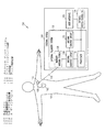
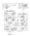
図1は、CRMシステム100の部分、およびシステム100を使用する環境の一部の実施形態の図である。システム100は、埋め込み式医療機器110と外部システム120を含む。図示の実施形態では、埋め込み式医療機器110は、患者の身体101に埋め込まれた後、リード・システム105を通して患者の心臓102に結合される。埋め込み式医療機器110の例は、ペースメーカ、電気的除細動器/除細動器、心臓再同期治療(CRT)機器、心臓再構築制御治療(RCT)機器、神経刺激器、薬物供給システム、生物学的治療機器、患者監視機器を含む。外部システム120によって、医師または他の介護者はRF遠隔測定リンク115を通して埋め込み式医療機器110と相互作用することができ、リンクは埋め込み式医療機器110と外部システム120の間に双方向データ通信を提供する。
FIG. 1 is a diagram of an embodiment of a portion of a
RF遠隔測定リンク115は、埋め込み式医療機器110から外部システム120へのデータ送信を実行する。これは、例えば埋め込み式医療機器110によって取得されたリアルタイムの生理学的データを送信すること、埋め込み式医療機器110が取得し、記憶した生理学的データを取り出すこと、埋め込み式医療機器110に記憶された治療履歴データを取り出すこと、埋め込み式医療機器110の動作状態(例えば電池の状態やリード線のインピーダンス)を示すデータを取り出すことを含む。RF遠隔測定リンク115は、外部システム120から埋め込み式医療機器110へのデータ送信も提供する。これは、例えば生理学的データを取得するために埋め込み式医療機器110をプログラムすること、少なくとも1つの自己診断試験(例えば機器の動作状態)を実行するよう埋め込み式医療機器110をプログラムすること、少なくとも1つの治療を施すために埋め込み式医療機器110をプログラムすることを含む。
The
RF遠隔測定リンク115は遠距離場遠隔測定リンクである。遠距離場は、フラウンホーファ領域とも呼ばれ、電磁放射源を送信することによって生成される電磁場の成分が1/rにほぼ比例して崩壊する領域を指し、ここでrは観察ポイントと放射源との間の距離である。したがって、遠距離場とは、r=λ/2πの境界の外側にある領域を指し、ここでλは送信される電磁エネルギの波長である。1つの実施形態では、RF遠隔測定リンク115の通信範囲(データを無線通信できる距離)は、少なくとも10フィート(3.1m)であるが、使用する通信技術で可能な限り長くてもよい。埋め込み式医療器具110の近傍に配置され、患者に取り付けられて、ケーブルで外部システム120に電気的に接続されたコイルを使用する誘導遠隔測定リンクとは異なり、RF遠隔測定リンク115を使用すると、患者はコイルやケーブルによって引き起こされる物理的制約から自由になり、埋め込み式医療機器110の埋め込みなどの手術中に、外部システム120を無菌場所から完全に離して配置することができる。
The
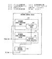
RF遠隔測定リンク115は、埋め込み式医療機器110の埋め込み遠隔測定システムと、外部システム120の外部遠隔測定システム122とによって支持される。外部遠隔測定システム122はダイバーシチ・アンテナ・システム126、アンテナ・インタフェース回路128、送受信器130、アンテナ制御回路132を含む。ダイバーシチ・アンテナ・システム126は、出力信号を埋め込み式医療機器110に送信し、入力信号を埋め込み式医療機器110から受信する複数のアンテナを含む。アンテナ・インタフェース回路128は、ダイバーシチ・アンテナ・システム126の同調回路を含み、ダイバーシチ・アンテナ・システム126と送受信器130の間で出力信号と入力信号の経路を指定する。送受信器130は、出力信号を変調することによって出力データ・フレームを送信し、入力信号を復調することによって入力データ・フレームを受信する。出力データ・フレームと入力データ・フレームはそれぞれ、ヘッダ、ペイロード、トレーラを含むデータの論理的単位であるフレームである。ヘッダは「コンマ」を含み、これはフレーム受信の信号を送るための一意のビット・セットを含む。コンマがないか、コンマを受信できないことは、フレーム受信の障害を示す。ペイロードは送信されるデータ・ブロックを含む。トレーラは、送信器が生成した値を有する巡回冗長検査(CRC)文字を含む。受信器は、そのCRC文字を受信し、さらに受信したデータ・ブロックに基づいてCRC文字を再計算して、その結果をトレーラ内の受信CRC文字と比較する。再計算したCRC文字が受信したCRC文字と一致した場合は、データが正確に送信されたとする。CRCエラーとは、再計算したCRC文字と受信したCRC文字との不一致を指す。特定の通信フォーマットに応じて、ヘッダとトレーラはそれぞれ、フラグをたてる、データ回復を制御する、かつ/または受信機器を同期させるために追加の情報を含む。様々な実施形態では、出力データ・フレームは、それぞれが複数のデータ・フレームを含む多フレーム・メッセージを含む。入力データ・フレームは、それぞれが1つまたは複数の出力データ・フレームに応答して埋め込み式医療機器110が生成した入力データ・フレームである応答フレームを含む。アンテナ制御回路132は、ダイバーシチ・アンテナ・システム126のほぼ最適な性能、または少なくとも許容可能な性能に対して、アンテナ・インタフェース回路の動作を制御する。様々な実施形態では、アンテナ制御回路132は、入力信号の品質に基づいて、ダイバーシチ・アンテナ・システム126のアクティブ・アンテナを選択する。このような品質は、例えば入力信号の強度および/または入力データ・フレームの完全性によって測定される。アンテナ制御回路132は、RF遠隔測定リンク115を介して双方向通信を実行する際に従う予め決めた通信プロトコルに基づいて、入力信号の品質を評価するタイミングを制御する。1つの実施形態では、アンテナ制御回路132は、入力信号における送信障害の検出に応答して、ダイバーシチ・アンテナ・システム126の異なるアクティブ・アンテナを選択する。このような送信障害は、ヌルまたは損傷したアンテナまたは性能が劣化したアンテナと関連する。外部遠隔測定システム122は外部システム制御装置124に接続され、これによって外部システム120は、埋め込み式医療機器110が取得した情報を受信し、埋め込み式医療機器110の動作を制御する。外部システム制御装置124は、送受信器130から入力データ・フレームを受信し、送受信器130に出力データ・フレームを送信する。ユーザ・インタフェース125によって、医師または他の介護者は受信した情報を見て、命令やパラメータを入力し、CRMシステム100の動作を制御することができる。
The
1つの実施形態では、外部システム120はプログラマを含む。別の実施形態では、図2に示すように、外部システム120は患者管理システムを含む。
In one embodiment,
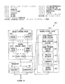
図2は、外部システム120の特定の実施形態である外部システム220の実施形態を示すブロック図である。図2に示すように、外部システム220は、外部機器234、遠隔通信ネットワーク236、1つまたは複数の遠隔機器238を含む患者管理システムである。外部機器234は、埋め込み式医療機器110の近傍に配置され、RF遠隔測定リンク115を介して埋め込み式医療機器110と通信する外部遠隔測定システム122を含む。1つまたは複数の遠隔機器238は、1つまたは複数の遠隔位置にあり、ネットワーク236を通して外部機器234と通信して、これによって医師または他の介護者が遠い距離から患者を監視して、治療する、かつ/または1つまたは複数の遠隔位置から様々な治療資源にアクセスすることができる。
FIG. 2 is a block diagram illustrating an embodiment of an
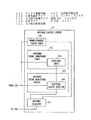
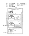
図3は、外部遠隔測定システム122の特定の実施形態である外部遠隔測定システム322の実施形態を示すブロック図である。外部遠隔測定システム322は、ダイバーシチ・アンテナ・システム326、アンテナ・インタフェース回路328、送受信器330、アンテナ制御回路332を含む。
FIG. 3 is a block diagram illustrating an embodiment of an
ダイバーシチ・アンテナ・システム326は、ダイバーシチ・アンテナ・システム126の特定の実施形態であり、2つ以上のアンテナ340A〜Nを含む。アンテナ340A〜Nはそれぞれ、埋め込み式医療機器110への出力信号の送信および/または埋め込み式医療機器110からの入力信号の受信を可能にする。1つの実施形態では、ダイバーシチ・アンテナ・システム126は2つのアンテナを含む。特定の実施形態では、2つのアンテナが、プログラマまたは外部機器234などの外部機器のシャーシに装着される。他の実施形態では、ダイバーシチ・アンテナ・システム126は3つ以上のアンテナを含む。ダイバーシチ・アンテナ・システム126の一例が、2005年2月28日出願の「DIVERSITY ANTENNA SYSTEM FOR COMMUNICATION WITH AN IMPLANTABLE MEDICAL DEVICE」と題した米国特許出願第11/068,497号で検討され、それは参照により全体が本明細書に組み込まれる。
アンテナ・インタフェース回路328は、アンテナ・インタフェース回路128の特定の実施形態であり、同調回路342A〜Nとスイッチ回路344を含む。同調回路342A〜Nはそれぞれ、アンテナ342A〜Nの対応するアンテナをチューニングする。スイッチ回路344は、アンテナ選択信号に従って、ダイバーシチ・アンテナ・システム326のアンテナと送受信器330の間を制御可能な状態で接続する。このアンテナは、出力信号の送信と入力信号の受信に使用される。1つの実施形態では、スイッチ回路344は、ダイバーシチ・アンテナ・システム326のアンテナと送受信器330との接続から、ダイバーシチ・アンテナ・システム326の別のアンテナと送受信器330との接続への変更を、約50マイクロ秒から1ミリ秒でほぼ完了する。
送受信器330は、送受信器130の特定の実施形態であり、変調器346と復調器348を含む。変調器346は、多フレーム・メッセージを形成する出力データ・フレームなどの出力データ・フレームでRF搬送波を変調することによって、出力信号を生成する。1つの実施形態では、出力信号のRF搬送波の周波数は、約902MHzから928MHzの範囲であり、約914MHzが特定の例である。出力信号のデータ送信速度は、毎秒約60キロビットから毎秒500キロビットの範囲であり、毎秒約204.8キロビットは特定の例である。復調器348は、受信した入力信号を復調することによって、入力データ・フレームを回復する。埋め込み式医療機器110の埋め込み遠隔測定回路は、入力データ・フレームで別のRF搬送波を変調することによって入力信号を生成する。1つの実施形態では、入力信号のRF搬送波の周波数は、約902MHzから928MHzの範囲であり、約914MHzが特定の例である。入力信号のデータ送信速度は、毎秒約60キロビットから毎秒約500キロビットの範囲であり、毎秒約102.4キロビットが特定の例である。入力データ・フレームは、それぞれが1つまたは複数の出力データ・フレームに続く応答フレームを含む。1つの実施形態では、振幅シフト・キーイング(ASK)が、出力信号と入力信号の両方に使用される変調方式である。変調器346はASK変調器であり、復調器348はASK復調器である。
The
アンテナ制御回路332は、アンテナ制御回路132の特定の実施形態であり、アンテナ選択信号を生成する。アンテナ制御回路332は、入力信号監視タイマ350、入力信号監視回路352、アンテナ・セレクタ354を含む。入力信号監視タイマ350は、予め決めた通信プロトコルに基づいて入力信号監視信号を生成する。通信プロトコルは、出力データ・フレームを送信するタイミング、および入力データ・フレームを受信するタイミングを決める。入力信号監視信号はそれぞれ、入力データ・フレームを受信するようにスケジュールされている場合に、入力信号の品質評価を可能にする。入力信号監視回路352は、各入力信号監視信号に応答して、入力信号の少なくとも1つの品質尺度を検出することによって、入力信号の品質指示を生成する。品質尺度の例は、入力信号におけるデータ送信エラーの存在や、入力信号の強度を含む。アンテナ・セレクタ354は、入力信号の品質指示に基づいてアンテナ選択信号を調節する。1つの実施形態では、アンテナ・セレクタ354は、予想された入力データ・フレームが予定の受信時間ウィンドウ内に検出されない場合に、ダイバーシチ・アンテナ・システム326の異なるアンテナを送受信器330に接続するためにアンテナ選択信号を調節する。別の実施形態では、アンテナ・セレクタ354は、入力信号から送信エラーが検出された場合に、ダイバーシチ・アンテナ・システム326の異なるアンテナを送受信器330に接続するために、アンテナ選択信号を調節する。別の実施形態では、アンテナ・セレクタ354は、ダイバーシチ・アンテナ・システム326の各アンテナに関連する入力信号の強度に基づいて、ダイバーシチ・アンテナ・システム326のアンテナを送受信器330に接続するために、アンテナ選択信号を調節する。
The
図4は、アンテナ制御回路332の特定の実施形態であるアンテナ制御回路432の実施形態を示すブロック図である。アンテナ制御回路432は、非応答性期間タイマ456、入力信号監視タイマ450、入力信号監視回路452、アンテナ・セレクタ454を含む。
FIG. 4 is a block diagram illustrating an embodiment of an
非応答期間タイマ456は、予め決めた通信プロトコルに従って応答フレームを受信すると予想された場合、多フレーム・メッセージの送信中に非応答期間を開始する。多フレーム・メッセージは、送受信器330に接続されたダイバーシチ・アンテナ・システム326のアクティブ・アンテナで送信される。予め決めた通信プロトコルに従って、多フレーム・メッセージの幾つかの出力データが送信された後、応答フレームの受信が予想される。非応答期間は、データ送信エラーがない状態で、応答フレームを受信する結果にならずにアンテナ選択信号を調節できる最大時間間隔である。入力信号の許容可能な信号品質を提供する別のアクティブ・アンテナが見つからないうちに非応答期間が尽きた場合は、異なるアクティブ・アンテナ、つまり多フレーム・メッセージの送信を最初に開始したものとは異なるアンテナを使用して、多フレーム・メッセージの送信を繰り返す。1つの実施形態では、非応答期間は、約50ミリ秒から1秒の範囲の予め決めた時間間隔であり、約100ミリ秒が特定の例である。
The
入力信号監視タイマ450は、入力信号監視タイマ350の特定の実施形態であり、応答タイマ458を含む。応答タイマ458は、予め決めた通信プロトコルに従って、応答フレームの受信が予想され、1つまたは複数の後続の応答フレームがある場合は、その受信が予想される場合に、多フレーム・メッセージの送信中に応答時間間隔を計数開始する。つまり、応答タイマ458は、それぞれが応答フレームの受信が予想される時間ウィンドウを表す応答時間間隔を計時する。1つの実施形態では、応答時間間隔は、約4ミリ秒から1秒の範囲の予め決めた時間間隔であり、約100ミリ秒が特定の例である。1つの実施形態では、応答時間間隔は、出力データ・フレームの送信終了時と次の出力データ・フレームの送信開始時の間の間隔と等しくなるように設定される。
Input
入力信号監視回路452は、入力信号監視回路352の特定の実施形態であり、応答障害検出器460を含む。応答タイマ458が応答時間間隔を計数開始した後、応答障害検出器460は、応答時間間隔中に応答障害を検出する。応答障害とは、応答フレームに関連するデータ送信エラーである。このようなデータ送信エラーの例は、応答フレームの受信障害、応答フレームのコンマの受信障害、応答フレームのCRCエラーを含む。応答障害検出器460の特定の例については、図5に関して以下で検討する。
Input
アンテナ・セレクタ454は、アンテナ・セレクタ354の特定の実施形態である。非応答期間中に、アンテナ・セレクタ454は、予め決めた応答時間間隔の間に応答障害が検出された場合、ダイバーシチ・アンテナ・システム326の異なるアンテナを送受信器330に接続するために、アンテナ選択信号を調節する。非応答期間に入力データ・フレームの受信に成功しない状態で、非応答期間が尽きると、アンテナ・セレクタ454は、ダイバーシチ・アンテナ・システム326の異なるアンテナを送受信器330に接続するために、アンテナ選択信号を調節する。ここで、異なるアンテナとは、多フレーム・メッセージの送信を開始したものとは異なるアンテナを指す。
図5は、応答障害検出器560の実施形態を示すブロック図であり、これは応答障害検出器460の特定の実施形態である。1つの実施形態では、図5に示すように、応答障害検出器560が応答欠如検出器562、コンマ欠如検出器564、CRC障害検出器566を含む。様々な他の実施形態では、応答障害検出器560は応答欠如検出器562、コンマ欠如検出器564、CRC障害検出器566のうち任意の1つまたは複数を含む。応答欠如検出器562、コンマ欠如検出器564、CRC障害検出器566のうち任意の1つまたは複数が、応答フレームに関連するデータ送信エラーを検出した場合に、応答障害が検出される。応答欠如検出器562は、応答時間間隔中に応答フレームを検出する。応答時間間隔中に応答フレームが検出されない場合に、応答障害が検出される。コンマ欠如検出器564は、応答時間間隔中に応答フレームの受信を示すコンマを検出する。応答時間間隔中にコンマが検出されない場合に、応答障害が検出される。CRC障害検出器556は、応答時間間隔中に入力信号からCRC障害を検出する。応答時間間隔中にCRC障害が検出された場合に、応答障害が検出される。
FIG. 5 is a block diagram illustrating an embodiment of
他の実施形態では、応答障害検出器560は、応答欠如、コンマ欠如、CRC障害とは異なるタイプのデータ送信エラーを検出する1つまたは複数のエラー検出器を含む。通常、応答障害検出器560は、予め決めたタイプのデータ送信エラーが応答障害を表す状態で、応答フレーム中の予め決めたタイプのデータ送信エラーを検出する。
In other embodiments, the
図6は、アンテナ制御回路632の実施形態を示すブロック図であり、これはアンテナ制御回路332の別の特定の実施形態である。アンテナ制御回路632は、試験フレーム生成器668、入力信号監視タイマ450、入力信号監視回路452、アンテナ・セレクタ654を含む。
FIG. 6 is a block diagram illustrating an embodiment of the
フレーム生成器668は、多フレーム・メッセージの送信前にアンテナ試験信号を生成する。アンテナ試験信号は、送受信器330に出力データ・フレームである試験フレームを送信させる。応答タイマ458は、試験フレームの送信後に応答時間間隔を計数開始する。応答障害検出器460は、応答時間間隔中に応答障害を検出する。
アンテナ・セレクタ654は、アンテナ・セレクタ354の別の特定の実施形態である。アンテナ・セレクタ654は、応答時間間隔中に応答障害が検出されると、ダイバーシチ・アンテナ・システム326の異なるアンテナを送受信器330に接続するために、アンテナ選択信号を調節する。1つの実施形態では、試験フレーム生成器668は、許容可能な品質の入力信号に関連するアンテナが見つかるまで、ダイバーシチ・アンテナ・システムの異なるアンテナを使用して、試験フレームを送信するためのアンテナ試験信号を生成する。別の実施形態では、アンテナを使用して受信した入力信号から応答障害が検出されると、そのアンテナは、許容不能な品質の入力信号に関連する唯一のアンテナとして選択解除される。応答障害が、アンテナの遭遇するヌルによって引き起こされた場合は、異なるアンテナもヌルに遭遇する確率が最低になる。1つの実施形態では、試験フレーム生成器668は、ダイバーシチ・アンテナ・システム326の全アンテナについて入力信号の品質が評価されるまで、ダイバーシチ・アンテナ・システムの異なるアンテナを使用して試験フレームを送信するためのアンテナ試験信号を生成する。
図7は、アンテナ制御回路732の実施形態を示すブロック図であり、これはアンテナ制御回路332の別の特定の実施形態である。アンテナ制御回路732は、入力信号監視タイマ450、入力信号監視回路452、アンテナ・セレクタ754を含む。応答タイマ458は、予め決めた通信プロトコルに従って応答フレームの受信が予想された場合に、応答時間間隔を計時する。応答障害検出器460は、応答時間間隔中に応答障害を検出する。
FIG. 7 is a block diagram illustrating an embodiment of the
アンテナ・セレクタ754は、アンテナ・セレクタ354の別の特定の実施形態である。アンテナ・セレクタ754は、多フレーム・メッセージの送信中に応答障害が検出されると、多フレーム・メッセージの送信後に、ダイバーシチ・アンテナ・システム326の異なるアンテナを送受信器330に接続するために、アンテナ選択信号を調節する。応答障害検出器460は、多フレーム・メッセージの送信中に応答障害を検出する。多フレーム・メッセージの送信中に複数の応答フレームの受信が予想される場合、いずれかの応答フレームに関連する1つの応答障害によって、アンテナ・セレクタ754がダイバーシチ・アンテナ・システム326の異なるアンテナを送受信器330に接続するためにアンテナ選択信号を調節する。アンテナ選択信号の調節は、多フレーム・メッセージの送信終了後に実行される。
図8は、アンテナ制御回路832の実施形態を示すブロック図であり、これはアンテナ制御回路332の別の特定の実施形態である。アンテナ制御回路832は、送信期間タイマ870、入力信号監視タイマ450、入力信号監視回路452、アンテナ・セレクタ854を含む。
FIG. 8 is a block diagram illustrating an embodiment of the
送信期間タイマ870は、それぞれが予め決めた数の出力データ・フレームを含む送信期間を計時する。送信期間は、予め決めた通信プロトコルに基づいて決定され、出力データ・フレームの数によって決められる。送信期間は、各送信期間中に少なくとも1つの応答フレームの受信が予想されるように、十分長い。例えば、応答フレームが予想されない状態で、最大5つの連続する出力データ・フレームを送信できた場合、この送信期間は、少なくとも6つの出力データ・フレームを含むと判断される。応答タイマ458は、予め決めた通信プロトコルに従って応答フレームの受信が予想される場合に、応答時間間隔を計時する。応答障害検出器460は、応答時期間中に応答障害を検出する。
The
アンテナ・セレクタ854は、アンテナ・セレクタ354の別の特定の実施形態である。アンテナ・セレクタ854は、送信期間中に応答障害が検出された場合に、各送信期間の終了時にダイバーシチ・アンテナ・システム326の異なるアンテナを送受信器330に接続するために、アンテナ選択信号を調節する。
図9は、アンテナ制御回路932の実施形態を示すブロック図であり、これはアンテナ制御回路332の別の特定の実施形態である。アンテナ制御回路932は、入力信号監視タイマ950、入力信号監視回路952、アンテナ・セレクタ954を含む。
FIG. 9 is a block diagram illustrating an embodiment of the
入力信号監視タイマ950は、入力信号監視タイマ350の別の特定の実施形態であり、信号強度計算タイマ972を含む。信号強度計算タイマ972は、多フレーム・メッセージの送信前に、信号強度計算信号を生成する。
Input
入力信号監視回路952は、入力信号監視回路352の別の特定の実施形態であり、信号強度検出器974、信号強度記憶回路976、信号強度計算器978を含む。信号強度検出器974は、それぞれがダイバーシチ・アンテナ・システム326の1つのアンテナに関連する入力信号の強度を表す強度パラメータを測定する。1つの実施形態では、信号強度検出器974は、アクティブ・アンテナになるようにアンテナを選択する度に、アンテナに関連する強度パラメータを測定する。信号強度記憶回路976は、測定した強度パラメータを記憶する。記憶された各強度パラメータには、その強度パラメータの最後の測定がいつ実行されたかを示すためにタイム・スタンプが与えられる。信号強度計算器978は、信号強度計算信号に応答して、ダイバーシチ・アンテナ・システム326の各アンテナの信号強度指数を計算する。信号強度指数は、記憶された強度パラメータと重み係数の関数である。重み係数は、強度パラメータの最後の測定から経過した時間の関数である。より新しく検出された強度パラメータの方が、信号強度指数の計算で、より重みが与えられる。
Input
アンテナ・セレクタ954は、アンテナ・セレクタ354の別の特定の実施形態である。アンテナ・セレクタ954は、信号強度計算信号に応答して、ダイバーシチ・アンテナ・システム326の全てのアンテナについて計算した強度指数に基づいて、ダイバーシチ・アンテナ・システム326のアンテナを送受信器330に接続するためにアンテナ選択信号を調節する。1つの実施形態では、アンテナ・セレクタ954は、最も高い強度指数に関連するアンテナを選択するために、アンテナ選択信号を調節する。
様々な実施形態では、アンテナ制御回路332は、本書を読み、理解した当業者が決定するように、1つまたは複数のアンテナ制御回路432、632、732、832、932を組み合わせる。概して、アンテナ制御回路は、任意の様々な方法を使用して、入力信号の品質を評価し、ダイバーシチ・アンテナ・システムのアンテナを、このアンテナまたは異なるアンテナについて評価した入力信号の品質に基づいて、アクティブ・アンテナになるように選択する。様々な実施形態では、ダイバーシチ・アンテナ・システムの2つ以上のアンテナがヌルに同時に遭遇する確率はごくわずかなため、1つのアンテナが許容不能な品質の入力信号に関連すると示された場合、1つまたは複数の異なるアンテナが、許容可能な品質の入力信号と関連するとされる。
In various embodiments, the
図10は、埋め込み式医療機器と通信する遠隔測定システムを操作する方法1000の実施形態を示す流れ図である。1つの実施形態では、遠隔測定システムは遠隔測定システム322を含む。
FIG. 10 is a flow diagram illustrating an embodiment of a
1010で、2つ以上のアンテナを含むダイバーシチ・アンテナ・システムを使用して、出力信号を送信し、入力信号を受信する。これは、出力信号を変調することによって出力データ・フレームを埋め込み式医療器具に送信すること、および入力信号を復調することによって入力データ・フレームを埋め込み式医療機器から受信することを含む。様々な実施形態では、送信された出力信号は、それぞれが複数の出力データ・フレームを含む多フレーム・メッセージによって変調される。様々な実施形態では、多フレーム・メッセージはそれぞれ、応答フレームを中断せずに連続して送信される2つ以上の出力データ・フレームを含む。 At 1010, a diversity antenna system that includes two or more antennas is used to transmit an output signal and receive an input signal. This includes transmitting the output data frame to the implantable medical device by modulating the output signal and receiving the input data frame from the implantable medical device by demodulating the input signal. In various embodiments, the transmitted output signal is modulated by a multi-frame message that includes a plurality of output data frames. In various embodiments, each multi-frame message includes two or more output data frames that are transmitted consecutively without interrupting the response frame.
1020で、アンテナ選択信号に従ってアクティブ・アンテナを選択する。アクティブ・アンテナとは、出力信号の送信および/または入力信号の受信に現在使用されているアンテナである。アンテナ選択信号は、どのアンテナがアクティブであるか指定する。 At 1020, an active antenna is selected according to the antenna selection signal. An active antenna is an antenna currently used for transmitting output signals and / or receiving input signals. The antenna selection signal specifies which antenna is active.
1030で、入力信号の品質尺度に基づいて、アンテナ選択信号を調節する。1032で、予め決めた通信プロトコルに基づいて、入力信号監視信号を生成する。この予め決めた通信プロトコルは、出力データ・フレームの送信タイミングと、入力データ・フレームの受信タイミングを特定する。入力信号監視信号は、入力信号の品質を評価すべき時間ウィンドウを示す。1034で、入力信号監視信号に応答して、ダイバーシチ・アンテナ・システムのアンテナに関連する入力信号について、品質指示を生成する。この品質指示は、入力信号における送信エラーの存在や、入力信号の強度など、入力信号の少なくとも1つの品質尺度を検出することによって、この品質指示が生成される。1036で、入力信号の品質指示に基づいて、アンテナ選択信号を調節する。入力信号の品質が許容不能と示された場合、ダイバーシチ・アンテナ・システムの異なるアンテナをアクティブ・アンテナになるものとして選択するために、アンテナ選択信号を調節する。ステップ1030の特定の例示的実施形態について、図11から図15に関して以下で検討する。
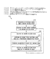
At 1030, the antenna selection signal is adjusted based on the quality measure of the input signal. At 1032, an input signal monitoring signal is generated based on a predetermined communication protocol. This predetermined communication protocol specifies the transmission timing of the output data frame and the reception timing of the input data frame. The input signal monitoring signal indicates a time window in which the quality of the input signal is to be evaluated. At 1034, in response to the input signal monitoring signal, a quality indication is generated for the input signal associated with the antenna of the diversity antenna system. This quality indication is generated by detecting at least one quality measure of the input signal, such as the presence of transmission errors in the input signal and the strength of the input signal. At 1036, the antenna selection signal is adjusted based on the quality indication of the input signal. If the quality of the input signal is indicated as unacceptable, the antenna selection signal is adjusted to select a different antenna of the diversity antenna system as the active antenna. Specific exemplary embodiments of
図11は、アンテナ選択信号を調節する方法1100の実施形態を示す流れ図である。方法1100は、方法1000の特定の実施形態である。特定の実施形態では、方法1100がアンテナ制御回路432によって実行される。
FIG. 11 is a flow diagram illustrating an embodiment of a
多フレーム・メッセージの送信中に、予め決めた通信プロトコルに従って応答フレームの受信が予想されると、1110で予め決めた非応答期間が開始する。ダイバーシチ・アンテナ・システムの第1アンテナを使用して、多フレーム・メッセージの送信を実行する。第1アンテナを使用して多フレーム・メッセージの2つ以上の出力データ・フレームを送信した後、応答フレームの受信が予想される。1つの実施形態では、予め決めた非応答期間は約50ミリ秒から1秒の範囲であり、100ミリ秒が特定の例である。 If a response frame is expected to be received according to a predetermined communication protocol during the transmission of the multi-frame message, a predetermined non-response period starts at 1110. The first antenna of the diversity antenna system is used to perform multi-frame message transmission. A response frame is expected to be received after transmitting more than one output data frame of the multi-frame message using the first antenna. In one embodiment, the predetermined non-response period ranges from about 50 milliseconds to 1 second, with 100 milliseconds being a specific example.
多フレーム・メッセージの送信中に、応答フレームの受信が予想され、1つまたは複数の後続の応答フレームがある場合、それぞれの受信が予想されると、1120で予め決めた応答時間間隔が開始する。1つの実施形態では、予め決めた応答時間間隔は約4ミリ秒から1秒の範囲であり、約100ミリ秒が特定の例である。1つの実施形態では、予め決めた応答時間間隔は、出力データ・フレームの送信終了時と次の出力データ・フレームの送信開始時の間の時間間隔によって制限される。 During the transmission of a multi-frame message, if a response frame is expected to be received and there are one or more subsequent response frames, a predetermined response time interval begins at 1120 when each reception is expected. . In one embodiment, the predetermined response time interval ranges from about 4 milliseconds to 1 second, with about 100 milliseconds being a specific example. In one embodiment, the predetermined response time interval is limited by the time interval between the end of transmission of the output data frame and the start of transmission of the next output data frame.
1130で、予め決めた応答時間間隔中に応答障害が検出される。応答障害は、応答フレームに関連するデータ送信エラーである。1つの実施形態では、応答フレームは、予め決めた応答時間間隔中に検出される。予め決めた応答時間間隔中に応答フレームが検出されない場合、応答障害が検出される。別の実施形態では、予め決めた応答時間間隔中に応答フレームの受信を示すコンマが検出される。予め決めた応答時間間隔中にコンマが検出されない場合、応答障害が検出される。別の実施形態では、予め決めた応答時間間隔中に応答フレームのCRC障害が検出される。予め決めた応答時間間隔中にCRC障害が検出されると、応答障害が検出される。別の実施形態では、応答フレーム、コンマ、CRC障害のうち1つまたは複数が検出される。予め決めた応答時間間隔中に、応答フレームが検出されない、またはコンマが検出されない、またはCRC障害が検出されない場合、応答障害が検出される。 At 1130, a response failure is detected during a predetermined response time interval. A response failure is a data transmission error associated with a response frame. In one embodiment, the response frame is detected during a predetermined response time interval. If a response frame is not detected during a predetermined response time interval, a response failure is detected. In another embodiment, a comma indicating receipt of a response frame is detected during a predetermined response time interval. If no comma is detected during a predetermined response time interval, a response failure is detected. In another embodiment, a CRC failure in the response frame is detected during a predetermined response time interval. If a CRC failure is detected during a predetermined response time interval, a response failure is detected. In another embodiment, one or more of response frames, commas, CRC faults are detected. If no response frame is detected or no comma is detected or no CRC failure is detected during a predetermined response time interval, a response failure is detected.
予め決めた応答時間間隔中に応答障害が検出されると、1140で、ダイバーシチ・アンテナ・システムの異なるアンテナをアクティブ・アンテナになるよう選択するために、アンテナ選択信号を調節する。多フレーム・メッセージの送信中に、2つ以上の応答フレームの受信が予想される場合、各応答フレームの受信が予想される時に予め決めた応答時間間隔が開始し、予め決めた応答時間間隔中に応答障害が検出されると、異なるアンテナを選択するために、アンテナ選択信号を調節する。 If a response failure is detected during a predetermined response time interval, at 1140, the antenna selection signal is adjusted to select a different antenna of the diversity antenna system to be the active antenna. If multiple response frames are expected to be received during transmission of a multi-frame message, a predetermined response time interval starts when each response frame is expected to be received, and during the predetermined response time interval If a response failure is detected, the antenna selection signal is adjusted to select a different antenna.
応答フレームを成功裏に受信することなく予め決めた非応答期間が尽きると、1150でダイバーシチ・アンテナ・システムの第2アンテナを選択するために、アンテナ選択信号を調節する。第2アンテナは、第1アンテナとは異なるアンテナである。つまり、予め決めた非応答期間中に、データ送信エラーがない状態で、入力データ・フレームを全く受信しない場合は、多フレーム・メッセージの送信を繰り返すか、別の多フレーム・メッセージの送信を実行するために、異なるアンテナを選択する。 When the predetermined non-response period has run out without successfully receiving the response frame, the antenna selection signal is adjusted at 1150 to select the second antenna of the diversity antenna system. The second antenna is an antenna different from the first antenna. In other words, if there is no data transmission error during the predetermined non-response period and no input data frame is received, repeat the transmission of a multi-frame message or execute another multi-frame message. To choose different antennas.
図12は、アンテナ選択信号を調節する方法1200の実施形態を示す流れ図である。方法1200は、方法1000の別の特定の実施形態である。特定の実施形態では、方法1200はアンテナ制御回路632によって実行される。
FIG. 12 is a flow diagram illustrating an embodiment of a
多フレーム・メッセージの送信前に、1210でアンテナ試験信号を生成する。アンテナ試験信号は、試験フレームを埋め込み式医療機器へと送信させ、これは試験フレームの受信後に応答フレームを送信する。試験フレームの送信後、1220で予め決めた応答時間間隔が開始する。予め決めた応答時間間隔中に、1230で応答障害が検出される。応答障害が検出された場合、1240でダイバーシチ・アンテナ・システムの異なるアンテナをアクティブ・アンテナになるように選択するために、アンテナ選択信号を調節する。1つの実施形態では、ダイバーシチ・アンテナ・システムの全アンテナで方法1200を繰り返す。別の実施形態では、現在アクティブなアンテナで応答障害が検出された場合、別のアンテナで方法1200を繰り返す。別の実施形態では、現在アクティブなアンテナで応答障害が検出された場合、異なるアンテナが許容可能な品質の入力信号に関連するものと仮定され、したがってこれが選択される。
An antenna test signal is generated at 1210 prior to transmission of the multi-frame message. The antenna test signal causes the test frame to be transmitted to the implantable medical device, which transmits a response frame after receiving the test frame. After the transmission of the test frame, a response time interval predetermined at 1220 starts. A response failure is detected at 1230 during a predetermined response time interval. If a response failure is detected, the antenna selection signal is adjusted at 1240 to select a different antenna of the diversity antenna system to be the active antenna. In one embodiment, the
図13は、アンテナ選択信号を調節する方法1300の実施形態を示す流れ図である。方法1300は、方法1000の別の特定の実施形態である。特定の実施形態では、方法1300はアンテナ制御回路732によって実行される。
FIG. 13 is a flow diagram illustrating an embodiment of a
多フレーム・メッセージの送信中に、応答フレームの受信が予想されると、1310で予め決めた応答時間間隔が開始する。予め決めた応答時間間隔中に、1320で応答障害が検出される。多フレーム・メッセージの送信中に応答障害が検出されると、1330で多フレーム・メッセージの送信後に、ダイバーシチ・アンテナ・システムの異なるアンテナをアクティブ・アンテナになるように選択するために、アンテナ選択信号を調節する。多フレーム・メッセージの送信中に2つ以上の応答フレームの受信が予想される場合、任意の応答フレームに関連して1つの応答障害があると、異なるアンテナがアクティブ・アンテナになるよう選択するために、アンテナ選択信号が調節される。 If a response frame is expected to be received during transmission of a multi-frame message, a response time interval predetermined at 1310 begins. A response failure is detected at 1320 during a predetermined response time interval. If a response failure is detected during transmission of a multi-frame message, the antenna selection signal is selected to select a different antenna of the diversity antenna system to become the active antenna after transmission of the multi-frame message at 1330. Adjust. If two or more response frames are expected to be received during the transmission of a multi-frame message, to select a different antenna to be the active antenna if there is one response failure associated with any response frame In addition, the antenna selection signal is adjusted.
図14は、アンテナ選択信号を調節する方法1400の実施形態を示す流れ図である。方法1400は、方法1000の別の特定の実施形態である。特定の実施形態では、方法1400はアンテナ制御回路832によって実行される。
FIG. 14 is a flow diagram illustrating an embodiment of a
1410で送信期間を計時する。送信期間は、所定数の出力データ・フレームが送信される期間を含む。出力データ・フレームを埋め込み式医療機器に送信する間に、送信期間が繰り返して計時される。予め決めた期間における出力データ・フレームの数は、予め決めた通信プロトコルに基づいて決定される。各送信期間中に、少なくとも1つの応答フレームの受信が予想される。送信期間中に応答フレームの受信が予想されると、1420で予め決めた応答時間間隔が開始する。予め決めた応答時間間隔中に、1430で応答障害が検出される。送信期間中に応答障害が検出されると、送信期間の終了時に、1440でダイバーシチ・アンテナ・システムの異なるアンテナをアクティブ・アンテナになるように選択するために、アンテナ選択信号を調節する。 In 1410, the transmission period is counted. The transmission period includes a period during which a predetermined number of output data frames are transmitted. While transmitting the output data frame to the implantable medical device, the transmission period is repeated and timed. The number of output data frames in a predetermined period is determined based on a predetermined communication protocol. During each transmission period, at least one response frame is expected to be received. If reception of a response frame is expected during the transmission period, a response time interval predetermined at 1420 starts. A response failure is detected at 1430 during a predetermined response time interval. If a response failure is detected during the transmission period, the antenna selection signal is adjusted to select a different antenna of the diversity antenna system to become the active antenna at 1440 at the end of the transmission period.
図15は、アンテナ選択信号を調節する方法1500の実施形態を示す流れ図である。方法1500は、方法1000の別の特定の実施形態である。特定の実施形態では、方法1500はアンテナ制御回路932によって実行される。
FIG. 15 is a flow diagram illustrating an embodiment of a
1510で、それぞれがアンテナに関連する強度パラメータを測定する。強度パラメータはそれぞれ、ダイバーシチ・アンテナ・システムの1つのアンテナによって受信された入力信号の強度を表す。強度パラメータの例は、入力信号の振幅とパワーを含む。1520で、強度パラメータを記憶する。強度パラメータがいつ測定されたかを示すために、記憶された各強度パラメータにタイム・スタンプを与える。多フレーム・メッセージの送信前に、1530で信号強度計算信号を生成する。1540で、信号強度計算信号に応答して信号強度指数を計算する。信号強度指数はそれぞれ、ダイバーシチ・アンテナ・システムの1つのアンテナに関連し、強度パラメータと重み係数に基づいて計算される。重み係数は、強度パラメータの測定から経過した時間の関数である。1550で、信号強度指数に基づいて、ダイバーシチ・アンテナ・システムのアンテナをアクティブ・アンテナになるように選択するために、アンテナ選択信号を調節する。1つの実施形態では、最高の信号強度指数に関連する、つまり最近測定した状態で最強の入力信号強度に関連するアンテナを選択するために、アンテナ選択信号を調節する。 At 1510, each measures an intensity parameter associated with the antenna. Each strength parameter represents the strength of the input signal received by one antenna of the diversity antenna system. Examples of intensity parameters include input signal amplitude and power. At 1520, the intensity parameter is stored. Each stored intensity parameter is time stamped to indicate when the intensity parameter was measured. A signal strength calculation signal is generated at 1530 prior to transmission of the multi-frame message. At 1540, a signal strength index is calculated in response to the signal strength calculation signal. Each signal strength index is associated with one antenna of the diversity antenna system and is calculated based on the strength parameter and the weight factor. The weighting factor is a function of the time that has elapsed since the measurement of the intensity parameter. At 1550, an antenna selection signal is adjusted to select an antenna of the diversity antenna system to be an active antenna based on the signal strength index. In one embodiment, the antenna selection signal is adjusted to select the antenna that is associated with the highest signal strength index, that is, the most recently measured signal that is associated with the strongest input signal strength.
方法1100、1200、1300、1400、1500は、入力信号の品質評価を計時し、実行する方法、および評価された入力信号の品質に基づいてアンテナ選択信号を調節する方法を示す特定の例示的実施形態である。様々な実施形態では、本書を読み、理解して、当業者によって決定されるように、これらの特定の実施形態を組み合わせ、他の特定の実施形態を使用することができる。概して、任意の実行可能な方法を使用して入力信号の品質を評価し、ダイバーシチ・アンテナ・システムのアンテナを、このアンテナまたは異なるアンテナについて評価した入力信号の品質に基づいて、アクティブ・アンテナになるように選択する。
図16は、外部遠隔測定システム1622の実施形態を示すブロック図であり、これは外部遠隔測定システム122の特定の実施形態である。外部遠隔測定システム1622は、ダイバーシチ・アンテナ・システム326、アンテナ・インタフェース回路328、送受信器330、アンテナ制御回路1632を含む。
FIG. 16 is a block diagram illustrating an embodiment of
アンテナ制御回路1632は、アンテナ制御回路132の特定の実施形態であり、フェージング検出器1650、アンテナ・セレクタ1652、アンテナ切り換えタイミング回路1654を含む。フェージング検出器1650は、ヌルに関連するとされる送信障害を検出する。フェージング検出器1650の特定の例示的実施形態を、図4から図8に関して以下で検討する。アンテナ・セレクタ1652は、送信障害の検出に応答して、ダイバーシチ・アンテナ・システム326の異なるアンテナを送受信器330に接続するために、アンテナ選択信号を調節する。アンテナ切り換えタイミング回路1654は、出力データ・フレームのフレームが送信されるか、入力データ・フレームのフレームが受信されている間、アンテナ選択信号を保留する。したがって、アンテナ・セレクタ1652がアンテナ選択信号を調節した後、送信または受信されるデータ・フレームがない場合、ダイバーシチ・アンテナ・システム326と送受信器330との接続が変更される。これは、接続の変更、つまり1つのアンテナから別のアンテナへの切り換えの結果として、潜在的データ送信エラーが生じるのを防止する。1つの実施形態では、アンテナ切り換えタイミング回路1654は、実行中のデータ・フレームの送信または受信が完了するまで、アンテナ・セレクタ1652によるアンテナ選択信号の調節を遅延させる。別の実施形態では、アンテナ切り換えタイミング回路1654は、実行中のデータ・フレームの送信または受信が完了するまで、調節されたアンテナ選択信号がスイッチ回路344へと与えられるのを抑制する。1つの実施形態では、アンテナ切り換えタイミング回路1654は、スイッチ回路344が1つのアンテナから別のアンテナへと切り換える切り換え時間が、1データ・ビットを送信するために必要な時間より有意に長くない場合のみデータ・フレームを送信または受信する間に、アンテナ選択信号を保留する。別の実施形態では、外部遠隔測定システム1622は、アンテナ選択信号の変更に応答して、切り換え回路344の動作によって引き起こされるデータ送信エラーを防止するエラー保護回路を含む。エラー保護回路は、エラー補正アルゴリズムを実行することによって、受信した入力データ・フレームで検出されたエラーを補正する。
The
図17は、外部遠隔測定システム1722の実施形態を示すブロック図であり、これは外部遠隔測定システム1622の特定の実施形態である。外部遠隔測定システム1722は、ダイバーシチ・アンテナ・システム326、アンテナ・インタフェース回路328、送受信器330、アンテナ制御回路1732を含む。
FIG. 17 is a block diagram illustrating an embodiment of
アンテナ制御回路1732は、アンテナ制御回路1632の特定の実施形態であり、入力フレーム障害検出器1750とアンテナ・セレクタ1752を含む。入力フレーム障害検出器1750は、フェージング検出器1650の特定の実施形態であり、入力信号からの送信障害として入力フレーム障害を検出する。入力フレーム障害は、少なくとも1つの入力データ・フレーム内のデータ送信エラーを含む。1つの実施形態では、1つの入力データ・フレーム内にある1つのデータ送信エラーは、ヌルに関連するとされる送信障害を構成する。入力フレーム障害検出器1750は、CRC障害検出器1756および/またはコンマ欠如検出器1758を含む。CRC障害検出器1756は、入力信号からCRC障害を検出し、CRC障害が検出されると、入力フレーム障害を示す。コンマ欠如検出器1758は、予め決めた時間ウィンドウ中に入力データ・フレームの受信を示すコンマを検出し、予め決めた時間ウィンドウ中にコンマが検出されない場合は、入力フレーム障害を示す。他の実施形態では、入力フレーム障害検出器1750は、CRC障害と、コンマ結語以外のタイプのデータ送信エラーとを検出する1つまたは複数のエラー検出器を含む。通常、入力フレーム障害検出器1750は、少なくとも1つの入力データ・フレーム内で予め決めたタイプのデータ送信エラーを検出し、予め決めたタイプのデータ送信エラーが検出されると、入力フレーム障害を示す。
アンテナ・セレクタ1752は、アンテナ・セレクタ1652の特定の実施形態であり、入力フレーム障害検出器1750が入力フレーム障害を示すと、ダイバーシチ・アンテナ・システム326の異なるアンテナを送受信器330に接続するために、アンテナ選択信号を調節する。1つの実施形態では、アンテナ・セレクタ1752は、CRC障害またはコンマ欠如の検出に応答して、アンテナ選択信号を調節する。調節されたアンテナ選択信号に応答して、スイッチ回路344は、別の入力フレーム障害が示されるまで、入力信号を受信し、出力信号を送信するために異なるアンテナを送受信器330に接続する。
図18は、外部遠隔測定システム1822の実施形態のブロック図であり、これは外部遠隔測定システム1622の別の特定の実施形態である。外部遠隔測定システム1822は、ダイバーシチ・アンテナ・システム326、アンテナ・インタフェース回路328、送受信器330、アンテナ制御回路1832を含む。
FIG. 18 is a block diagram of an embodiment of an
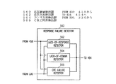
アンテナ制御回路1832は、アンテナ制御回路1632の特定の実施形態であり、応答障害検出器1850とアンテナ・セレクタ1852を含む。応答障害検出器1850は、フェージング検出器1650の特定の実施形態であり、入力信号からの送信障害として応答障害を検出する。応答障害は、入力データ・フレームの少なくとも1つの応答フレームにあるデータ送信エラーを含む。応答フレームは、埋め込み式医療機器110に送信された出力データ・フレームに応答して埋め込み式医療機器110が生成し、送信した入力データ・フレームである。1つの実施形態では、1つの応答フレーム内にある1つのデータ送信エラーは、ヌルに関連するとされる送信障害を構成する。応答障害検出器1850は、CRC障害検出器1856および/または応答欠如検出器1858を含む。CRC障害検出器1856は、入力信号からCRC障害を検出し、CRC障害が検出されると、応答障害を示す。応答欠如検出器1858は、埋め込み式医療機器110に送信された出力データ・フレームの受信を示す応答フレームを検出し、出力データ・フレームの送信から開始する予め決めた時間ウィンドウ中に応答フレームが検出されないと、応答障害を示す。
アンテナ・セレクタ1852は、アンテナ・セレクタ1652の特定の実施形態であり、応答障害が示されると、ダイバーシチ・アンテナ・システム326の異なるアンテナを送受信器330に接続するために、アンテナ選択信号を調節する。1つの実施形態では、アンテナ・セレクタ1852は、CRC障害または応答の欠如の検出に応答して、アンテナ選択信号を調節する。調節されたアンテナ選択信号に応答して、スイッチ回路344は、別の応答障害の検出が示されるまで、入力信号を受信し、出力信号を送信するために異なるアンテナを送受信器330に接続する。
図19は、外部遠隔測定システム1922の実施形態を示すブロック図であり、これは外部遠隔測定システム1622の別の特定の実施形態である。外部遠隔測定システム1922はダイバーシチ・アンテナ・システム326、アンテナ・インタフェース回路328、送受信器330、アンテナ制御回路1932を含む。
FIG. 19 is a block diagram illustrating an embodiment of an
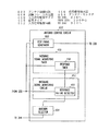
アンテナ制御回路1932は、アンテナ制御回路163の特定の実施形態であり、信号強度障害検出器1950とアンテナ・セレクタ1952を含む。信号強度障害検出器1950は、フェージング検出器1650の特定の実施形態であり、入力信号からの送信障害として信号強度障害を検出する。信号強度障害検出器1950によって検出される信号強度障害は、ヌルが原因とされる。信号強度障害検出器1950は、信号強度検出器1960、信号強度平均化回路1961、閾値生成器1962、比較器1964を含む。信号強度検出器1960は、入力信号の強度の尺度である強度パラメータを測定する。1つの実施形態では、強度パラメータは、dBm(ワット(W)から1ミリワット(1mW)のデシベル比率(log10))単位で測定したパワーであり、信号強度検出器1960は信号パワー検出器を含む。別の実施形態では、強度パラメータは、ボルト単位で測定された振幅であり、信号強度検出器1960は信号振幅検出器を含む。信号強度平均化回路1961は測定された強度パラメータの平均値を計算する。1つの実施形態では、信号強度平均化回路1961は、予め決めた期間にわたって強度パラメータの平均値を計算する。別の実施形態では、信号強度平均化回路1961は、予め決めたフレーム数にわたって強度パラメータの平均値を計算する。特定の実施形態では、予め決めた数は4から50フレームの範囲であり、約6フレームが特定の例である。閾値生成器1962は、測定された強度パラメータの平均値に基づいて、閾値強度を動的に生成する。1つの実施形態では、閾値強度は、測定された強度パラメータの平均値から予め決めたマージンを引くことによって生成される。1つの特定の実施形態では、予め決めたマージンは約10dBmから30dBmの範囲であり、約20dBmが特定の例である。比較器1964は、測定された強度パラメータの平均値を受信する入力部、動的に生成された閾値強度を受信する別の入力部、測定された強度パラメータの平均値が、動的に生成された閾値強度よりも低下した場合に信号強度障害を示す出力部を含む。
The
アンテナ・セレクタ1952は、アンテナ・セレクタ1652の特定の実施形態であり、比較器1964が信号強度障害を示した場合に、ダイバーシチ・アンテナ・システム326の異なるアンテナを送受信器330に接続するために、アンテナ選択信号を調節する。1つの実施形態では、アンテナ・セレクタ1952は、信号強度障害の指示に応答して、アンテナ選択信号を即座に調節する。別の実施形態では、約20ミリ秒から200ミリ秒の範囲で、約50ミリ秒が特定の例である予め決めた時間間隔で、信号強度障害が示されると、アンテナ・セレクタ1952がアンテナ選択信号を調節する。調節されたアンテナ選択信号に応答して、スイッチ回路344は、別の信号強度障害の検出が示されるまで、入力信号を受信し、出力信号を送信するために、異なるアンテナを送受信器330に接続する。
The
図20は、外部遠隔測定システム2022の実施形態を示すブロック図であり、これは外部遠隔測定システム1622の別の特定の実施形態である。外部遠隔測定システム2022は、ダイバーシチ・アンテナ・システム326、アンテナ・インタフェース回路328、送受信器330、アンテナ制御回路2032を含む。
FIG. 20 is a block diagram illustrating an embodiment of an
アンテナ制御回路2032は、アンテナ制御回路1632の特定の実施形態であり、信号強度障害検出器2050とアンテナ・セレクタ2052を含む。信号強度障害検出器2050は、フェージング検出器1650の別の特定の実施形態であり、出力信号に関連する信号強度障害を送信障害として検出する。信号強度障害検出器2050は、信号強度受信器2065および/または肯定応答信号受信器2066を含む。信号強度受信器2065は、出力フレームの受信の際に信号強度障害を検出する埋め込み式医療機器110が生成し、送信した入力データ・フレームである報告フレームを受信する。信号強度受信器2065は、報告フレームが出力信号に関連する信号強度障害を示すデータを含む場合に、信号強度障害を示す。肯定応答信号受信器2066は、入力データ・フレームの肯定応答フレームを受信し、出力フレームを埋め込み式医療機器110に送信した後、予め決めた時間間隔内に肯定応答フレームが受信されない場合は、信号強度障害を示す。肯定応答フレームは、埋め込み式医療機器110が出力フレームを成功裏に受信したことを示す。
アンテナ・セレクタ2052は、アンテナ・セレクタ1652の特定の実施形態であり、信号強度障害が示されると、ダイバーシチ・アンテナ・システム326の異なるアンテナを送受信器330に接続するためにアンテナ選択信号を調節する。1つの実施形態では、アンテナ・セレクタ2052は、埋め込み式医療機器110が受信したままの出力信号内で信号強度障害を示すデータ・フレームを受信するか、肯定応答フレームが欠如していることに応答して、アンテナ選択信号を調節する。調節されたアンテナ選択信号に応答して、スイッチ回路344は、別の信号強度障害の検出が示されるまで、入力信号を受信し、出力信号を送信するために、異なるアンテナを送受信器330に接続する。
図21は、外部遠隔測定システム2122の実施形態のブロック図であり、これは外部遠隔測定システム1622の別の特定の実施形態である。外部遠隔測定システム2122は、ダイバーシチ・アンテナ・システム326、アンテナ・インタフェース回路328、送受信器330、アンテナ制御回路2132を含む。
FIG. 21 is a block diagram of an embodiment of an
アンテナ制御回路2132は、アンテナ制御回路1632の特定の実施形態であり、信号強度障害検出器2150とアンテナ・セレクタ2152を含む。信号強度障害検出器2150は、フェージング検出器1650の別の特定の実施形態であり、入力信号と出力信号に関連する信号強度障害を検出する。信号強度障害検出器2150は、入力信号強度障害検出器2168と出力信号強度障害検出器2170を含む。入力信号強度障害検出器2168は、入力信号に関連する信号強度障害を送信障害として検出し、信号強度障害が検出されると、入力信号強度障害を示す。1つの実施形態では、入力信号強度障害検出器2168は、信号強度障害検出器1950と実質的に同一であるか、類似している。出力信号強度障害検出器2170は、出力信号に関連する信号強度障害を送信障害として検出し、信号強度障害が検出されると、出力信号強度障害を示す。1つの実施形態では、出力信号強度障害検出器2170は、信号強度障害検出器2050と実質的に同一であるか、類似している。
アンテナ・セレクタ2152は、受信アンテナ・セレクタ2172と送信アンテナ・セレクタ2174を含む。受信アンテナ・セレクタ2172は、入力信号強度障害の検出が示されると、入力信号を受信するためにダイバーシチ・アンテナ・システム326の異なるアンテナを選択するようにアンテナ選択信号を調節する。送信アンテナ・セレクタ2174は、出力信号強度障害の検出が示されると、出力信号を送信するためにダイバーシチ・アンテナ・システム326の異なるアンテナを選択するようにアンテナ選択信号を調節する。1つの実施形態では、アンテナ選択信号によって、2つの異なるアンテナを選択することができる。1つは入力信号の受信用で、他は出力信号の送信用である。別の実施形態では、アンテナ選択信号によって、入力信号を受信し、出力信号を送信するために、1つのアンテナまたは2つの異なるアンテナを選択することができる。
The
様々な他の特定の実施形態では、フェージング検出器1650が、入力フレーム障害検出器1750、応答障害検出器1850、信号強度障害検出器1950、信号強度障害検出器2050、信号強度障害検出器2150のうち1つまたは複数の要素を選択的に含む。1つの例示的実施形態では、フェージング検出器1650は、入力フレーム障害検出器1750(またはその一部)および信号強度障害検出器1950(またはその一部)を含む。アンテナ・セレクタ1752は、入力フレーム障害または信号強度障害の検出に応答して、アンテナ選択信号を調節する。別の実施形態では、フェージング検出器1650は、入力フレーム障害検出器1750、応答障害検出器1850、信号強度障害検出器2150を含む。アンテナ・セレクタ1752は、入力フレーム障害、応答障害、入力信号強度障害、出力信号強度障害のいずれかの検出に応答して、アンテナ選択信号を調節する。このような実施形態を含む他の実施形態は、本書を読み、理解すると、当業者には明白になる。
In various other specific embodiments, fading
図22は、外部遠隔測定システム2222の実施形態を示すブロック図であり、これは外部遠隔測定システム122の別の特定の実施形態である。外部遠隔測定システム2222は、ダイバーシチ・アンテナ・システム326、アンテナ・インタフェース回路328、送受信器330、アンテナ制御回路2232を含む。
FIG. 22 is a block diagram illustrating an embodiment of an
アンテナ制御回路2232は、アンテナ制御回路132の別の特定の実施形態であり、選択シーケンス生成器2276と切り換えタイマ2278を含む。選択シーケンス生成器2276は、アンテナ切り換えタイミング信号に応答して、送受信器330に接続すべきダイバーシチ・アンテナ・システム326のアンテナを選択するために、アンテナ選択信号を生成する。アンテナは、入力信号の受信と出力信号の送信に使用される。1つの実施形態では、選択シーケンス生成器2276は、ランダム・シーケンスを動的に生成し、動的に生成されたランダム・シーケンスに従ってアンテナ切り換えタイミング信号に応答してダイバーシチ・アンテナ・システム326のアンテナを選択するように、アンテナ選択信号を生成するランダム・シーケンス生成器を含む。別の実施形態では、選択シーケンス生成器2276は、内蔵シーケンスまたはプログラムされたシーケンスなどの予め決めたシーケンスに従って、アンテナ切り換えタイミング信号に応答してダイバーシチ・アンテナ・システム326のアンテナを選択するために、アンテナ選択信号を生成する予め決めたシーケンス生成器を含む。切り換えタイマ2278は、新しいアンテナを選択すべき時間を特定する予め決めたスケジュールに従って、アンテナ切り換えタイミング信号を生成する。1つの実施形態では、予め決めたスケジュールは、約50ミリ秒から500ミリ秒の範囲である予め決めた期間を含み、約200ミリ秒が特定の例である。切り換えタイマ2278は、この予め決めた期間を使用して、周期的にアンテナ切り換えタイミング信号を生成する。1つの実施形態では、切り換えタイマ2278は、出力データ・フレームのフレームが送信されているか入力データ・フレームのフレームが受信されている間に、アンテナ切り換えタイミング信号を保留する切り換え保留回路を含む。これは、データ・フレームの送受信中に1つのアンテナから別のアンテナに切り換えることによって引き起こされる可能性があるデータ送信エラーを防止する。1つの実施形態では、切り換えタイマ2278は、実行中のデータ・フレームの送信または受信が完了するまで、アンテナ切り換えタイミング信号の生成を遅延させる。別の実施形態では、切り換えタイマ2278は、実行中のデータ・フレームの送信または受信が完了するまで、アンテナ選択信号の変更がスイッチ回路344へと与えられるのを抑制する。
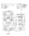
図23は、外部遠隔測定システム2322の実施形態を示すブロック図であり、これは外部遠隔測定システム122の別の特定の実施形態である。外部遠隔測定システム2322は、ダイバーシチ・アンテナ・システム326、アンテナ・インタフェース回路2328、送受信器2330、アンテナ制御回路2332を含む。
FIG. 23 is a block diagram illustrating an embodiment of an
アンテナ・インタフェース回路2328は、アンテナ・インタフェース回路128の特定の実施形態であり、同調回路342A〜Nを含む。同調回路342A〜Nはそれぞれ、アンテナ342A〜Nのうち対応するアンテナをチューニングする。
送受信器2330は、送受信器130の特定の実施形態であり、複数の受信モジュール2380A〜Nとスイッチ回路2382を含む。受信モジュール2380A〜Nはそれぞれ、同調回路342A〜Nのうち対応する同調回路を通してアンテナ342A〜Nのうち対応するアンテナに結合される入力部を有する。スイッチ回路2382は、受信モジュール2380A〜Nのうち1つの受信モジュールの出力部を、受信パス選択信号に従って外部システム制御装置124に接続する。つまり、受信モジュール2380A〜Nのうち1つが処理した入力信号が、受信パス選択信号に従って外部システム制御装置124によって使用するために選択される。
The
アンテナ制御回路2332は、アンテナ制御回路132の特定の実施形態であり、受信パス選択信号を生成する。外部遠隔測定システム1622〜2222の場合のように、1つのアクティブ・アンテナを選択するのではなく、遠隔測定セッションを通じて2つ以上のアンテナ340A〜Nがアクティブである。アンテナ制御回路2332は、そのアンテナを含む受信パスを選択することにより、有効アンテナを選択する。各受信パスは、アンテナ340A〜Nのアンテナ、同調回路342A〜Nのうち対応同調回路、受信モジュール2380A〜Nのうち対応する受信モジュールを含む。例えば、受信パスの1つはアンテナ340A、同調回路342A、受信モジュール2380Aを含む。受信パスを選択することは、受信モジュール2380A〜Nのうち1つの受信モジュールの出力部を外部システム制御装置124に接続することを含む。アンテナ制御回路2332は、信号品質評価回路2384、受信パス・セレクタ2386、パス切り換えタイミング回路2388を含む。
The
信号品質評価回路2384は、受信モジュール2380A〜Nそれぞれが処理した入力信号の品質指示を生成する。図示の実施形態では、信号品質評価回路2384は、入力フレーム障害検出器2390と信号強度検出器2392を含む。入力フレーム障害検出器2390は、受信モジュール2380A〜Nそれぞれが処理入力信号から入力フレーム障害を検出する。1つの特定の実施形態では、入力フレーム障害検出器2390は、受信モジュール2380A〜Nそれぞれが処理した受信信号からCRC障害を検出し、CRC障害が検出された受信モジュールがあれば、その入力フレーム障害を示すCRC障害検出器を含む。別の特定の実施形態では、入力フレーム障害検出器2390は、予め決めた時間ウィンドウ中に受信モジュール2380A〜Nそれぞれが処理した入力信号からデータ・フレームを示すコンマを検出し、コンマドが検出されない受信モジュールがあれば、その入力フレーム障害を示すように適合されたコンマ欠如検出器を含む。信号強度検出器2392は、受信モジュール2380A〜Nそれぞれが処理した入力信号の強度の尺度である強度パラメータを測定する。1つの実施形態では、信号強度検出器2392は、受信モジュール2380A〜Nそれぞれが処理した入力信号に関連する入力信号強度障害を検出する入力信号強度障害検出器を含む。特定の実施形態では、入力信号強度障害検出器は、信号強度障害検出器1950と実質的に同一であるか、類似している。
The signal
受信パス・セレクタ2386は、受信モジュール2380A〜Nのために生成された入力信号の品質指示に基づいて、受信パス選択信号を調節する。品質指示は、入力フレーム障害と入力信号強度障害のうち一方または両方を含む。受信パス・セレクタ2386は、入力フレーム障害と入力信号強度障害のうち少なくとも1つが検出された受信パスがあれば、全て選択解除するように受信パス選択信号を調節する。1つの実施形態では、受信パス・セレクタ2386は、受信パスについて測定された強度パラメータに基づいて、受信パス選択信号を調節する。
パス切り換えタイミング回路2388は、出力データ・フレームのフレームが送信されるか、入力データ・フレームのフレームが受信されている間、受信パス選択信号を保留する。これは、データ・フレームの送受信中に1つの受信パスから別の受信パスに切り換えることによって引き起こされる可能性があるデータ送信エラーを防止する。1つの実施形態では、パス切り換えタイミング回路2388は、実行中のデータ・フレームの送信または受信が完了するまで、受信パス選択信号の調節を遅延させる。別の実施形態では、パス切り換えタイミング回路2388は、実行中のデータ・フレームの送信または受信が完了するまで、受信パス選択信号の変更がスイッチ回路2382に与えられるのを抑制する。
The path switching
図24は、埋め込み式医療機器と通信する遠隔測定システムを操作する方法を示す流れ図である。1つの実施形態では、方法は、本書で検討した特定の実施形態を含む外部遠隔測定システム1622によって実行される。
FIG. 24 is a flow diagram illustrating a method of operating a telemetry system that communicates with an implantable medical device. In one embodiment, the method is performed by an
2400で、2つ以上のアンテナを含むダイバーシチ・アンテナ・システムを使用して、信号を送信し、受信する。これは、出力信号を埋め込み式医療機器に送信することと、入力信号を埋め込み式医療機器から受信することを含む。出力信号は、埋め込み式医療機器と通信する遠隔測定システムによって出力データ・フレームで変調されたRF搬送波信号を含む。入力信号は、埋め込み式医療機器によって入力データ・フレームで変調された別のRF搬送波信号を含む。入力データ・フレームは、受信した入力信号を復調することによって回復される。1つの実施形態では、ASKが、出力信号および入力信号の変調に使用される変調方式である。 At 2400, a diversity antenna system that includes two or more antennas is used to transmit and receive signals. This includes transmitting an output signal to the implantable medical device and receiving an input signal from the implantable medical device. The output signal includes an RF carrier signal modulated with an output data frame by a telemetry system in communication with the implantable medical device. The input signal includes another RF carrier signal that is modulated with an input data frame by the implantable medical device. The input data frame is recovered by demodulating the received input signal. In one embodiment, ASK is a modulation scheme used to modulate output and input signals.
2410で、アンテナ選択信号に従ってアクティブ・アンテナを選択する。アクティブ・アンテナとは、信号の送受信に現在使用されているアンテナである。アンテナ選択信号が、ダイバーシチ・アンテナ・システムのうち、どの1つまたは複数のアンテナがアクティブであるかを制御する。 At 2410, an active antenna is selected according to the antenna selection signal. An active antenna is an antenna currently used for transmitting and receiving signals. An antenna selection signal controls which one or more antennas of the diversity antenna system are active.
2420で、ヌルに関連するとされる送信障害を検出する。ヌルは、このような送信障害を引き起こすことが知られている。送信障害の例は、入力フレーム障害、応答フレーム障害、信号強度障害を含む。1つまたは複数のタイプのこのような送信障害が、埋め込み式医療機器と通信する遠隔測定システムによってヌルの指示として検出される。入力フレーム障害は、例えば入力信号からCRC障害またはコンマの欠如を検出することによって検出される。応答フレーム障害は、例えば入力信号からCRC障害または応答フレームの欠如を検出することによって検出される。応答フレームは、埋め込み式医療機器に送信される出力データ・フレームに応答して、埋め込み式医療機器から送信される。応答フレームの欠如は、出力データ・フレームが埋め込み式医療機器に送信された後、予め決めた期間内に検出される。信号強度障害は、例えば出力信号および/または入力信号の振幅またはパワーなどの強度パラメータの突然の低下を検出することによって検出される。強度パラメータは、埋め込み式医療機器と通信する遠隔測定システムによって、埋め込み式医療機器によって、またはその両方によって測定される。1つの実施形態では、埋め込み式医療機器が測定し、報告した通りの出力信号の信号強度に基づいて、出力信号を埋め込み式医療機器に送信するための送信アンテナが選択され、埋め込み式医療機器と通信する遠隔測定システムが測定した通りの入力信号の信号強度に基づいて、入力信号を埋め込み式医療機器から受信する受信アンテナが選択される。 At 2420, a transmission failure that is associated with a null is detected. Nulls are known to cause such transmission failures. Examples of transmission failures include input frame failures, response frame failures, and signal strength failures. One or more types of such transmission failures are detected as a null indication by a telemetry system in communication with the implantable medical device. Input frame failure is detected, for example, by detecting CRC failure or lack of commas from the input signal. Response frame failure is detected, for example, by detecting CRC failure or lack of response frame from the input signal. The response frame is transmitted from the implantable medical device in response to the output data frame transmitted to the implantable medical device. The lack of a response frame is detected within a predetermined period after the output data frame is transmitted to the implantable medical device. Signal strength impairments are detected by detecting a sudden drop in strength parameters such as, for example, the amplitude or power of the output signal and / or input signal. The intensity parameter is measured by a telemetry system in communication with the implantable medical device, by the implantable medical device, or both. In one embodiment, based on the signal strength of the output signal as measured and reported by the implantable medical device, a transmit antenna for transmitting the output signal to the implantable medical device is selected, and the implantable medical device and A receiving antenna that receives the input signal from the implantable medical device is selected based on the signal strength of the input signal as measured by the communicating telemetry system.
送信障害が検出されると、2430で、異なるアクティブ・アンテナを選択するために、アンテナ選択信号を調節する。つまり、ヌルに遭遇したとされると、遠隔測定システムは、現在使用されているアンテナから異なるアンテナへと切り換える。遠隔測定システムの2つのアンテナが同時にヌルに遭遇する可能性は非常に低い。 If a transmission failure is detected, at 2430 the antenna selection signal is adjusted to select a different active antenna. That is, if a null is encountered, the telemetry system switches from the currently used antenna to a different antenna. It is very unlikely that the two antennas of the telemetry system will encounter a null at the same time.
2440では、フレームの送受信中に、アンテナ選択信号を保留する。データ送信エラーを防止するために、アンテナ選択信号は、データ・フレームが送信または受信されてない時に実際にアンテナを切り換えさせる。これは、アンテナの切り換えを完了するために必要な時間が、データ・ビットの送受信に必要な時間より大幅に短くない場合、特に重要である。1つの実施形態では、アンテナの切り換えを完了するために必要な時間が、データ・ビットの送受信に必要な時間より大幅に短い場合、データ・フレームを送信または受信している間に、アンテナを切り換えることができる。別の実施形態では、潜在的なデータ送信エラーを補正するためにエラー補正アルゴリズムを実行している場合、データ・フレームを送信または受信している間にアンテナを切り換えることができる。 At 2440, the antenna selection signal is held during frame transmission / reception. In order to prevent data transmission errors, the antenna selection signal actually causes the antenna to switch when no data frame is transmitted or received. This is particularly important when the time required to complete the antenna switch is not significantly shorter than the time required to transmit and receive data bits. In one embodiment, when the time required to complete the antenna switch is significantly shorter than the time required to send and receive data bits, the antenna is switched while transmitting or receiving data frames. be able to. In another embodiment, the antenna can be switched while transmitting or receiving data frames if an error correction algorithm is running to correct potential data transmission errors.
2450では、調節されたアンテナ選択信号に従って、異なるアクティブ・アンテナを選択する。この新しく選択されたアクティブ・アンテナは、別の送信障害が検出されるまで、データ・フレームの送受信に使用される。遠隔測定セッション中に、ステップ2420〜2450を繰り返して、送信障害を連続的に監視し、送信障害が検出された場合は、異なるアンテナに切り換える。 At 2450, a different active antenna is selected according to the adjusted antenna selection signal. This newly selected active antenna is used to transmit and receive data frames until another transmission failure is detected. During a telemetry session, steps 2420-2450 are repeated to continuously monitor transmission faults and switch to a different antenna if transmission faults are detected.
図25は、埋め込み式医療機器と通信する遠隔測定回路を操作する別の方法を示す流れ図である。1つの実施形態では、方法は外部遠隔測定システム2222によって実行される。
FIG. 25 is a flow diagram illustrating another method of operating a telemetry circuit in communication with an implantable medical device. In one embodiment, the method is performed by
2500で、2つ以上のアンテナを含むダイバーシチ・アンテナ・システムを使用して、信号を送信し、受信する。これは、ステップ2400について以上で検討したように、出力信号を埋め込み式医療機器に送信することと、入力信号を埋め込み式医療機器から受信することを含む。
At 2500, signals are transmitted and received using a diversity antenna system including two or more antennas. This includes transmitting the output signal to the implantable medical device and receiving the input signal from the implantable medical device, as discussed above for
2510で、アンテナ選択信号に従ってアクティブ・アンテナを選択する。アクティブ・アンテナは、送受信アンテナ用に現在使用されているアンテナである。アンテナ選択信号は、ダイバーシチ・アンテナ・システムのどの1つまたは複数のアンテナがアクティブであるかを制御する。 At 2510, an active antenna is selected according to the antenna selection signal. An active antenna is an antenna currently used for transmitting and receiving antennas. The antenna selection signal controls which one or more antennas of the diversity antenna system are active.
2520で、予め決めたスケジュールに基づいて新しいアクティブ・アンテナを選択するために、アンテナ選択信号を生成する。つまり、予め決めたスケジュールによって特定された時間に、アンテナ選択信号を調節する。アンテナ選択信号は、遠隔測定システムがヌルに遭遇する確率を低下させる、または最低限に抑えるために、アンテナ選択シーケンスに従って調節される。アンテナ選択シーケンスの生成方法に応じて、新しいアクティブ・アンテナは、現在使用されているものと同じアンテナ、または異なるアンテナでよい。1つの実施形態では、新しいアクティブ・アンテナは常に、現在使用されているアンテナとは異なる。1つの実施形態では、動的に生成されたランダム・シーケンスに基づいて、アンテナ選択信号が生成される。代替実施形態では、予め決めたシーケンスに基づいてアンテナ選択信号が生成される。1つの実施形態では、新しいアクティブ・アンテナを周期的に選択する。さらなる実施形態では、フレームを送信または受信している間に、アンテナ選択信号は保留される。 At 2520, an antenna selection signal is generated to select a new active antenna based on a predetermined schedule. That is, the antenna selection signal is adjusted at a time specified by a predetermined schedule. The antenna selection signal is adjusted according to an antenna selection sequence to reduce or minimize the probability that the telemetry system will encounter a null. Depending on how the antenna selection sequence is generated, the new active antenna may be the same antenna that is currently used or a different antenna. In one embodiment, the new active antenna is always different from the currently used antenna. In one embodiment, an antenna selection signal is generated based on a dynamically generated random sequence. In an alternative embodiment, the antenna selection signal is generated based on a predetermined sequence. In one embodiment, a new active antenna is selected periodically. In a further embodiment, the antenna selection signal is suspended while transmitting or receiving a frame.
遠隔測定セッション中に、ステップ2510〜2520を繰り返して、予め決めた周期など、予め決めた時間でアンテナ選択信号を調節する。遠隔測定システムが埋め込み式医療機器と通信する間に、ヌルの位置とアクティブ・アンテナの位置が両方とも変動するので、遠隔測定システムがヌルに遭遇する確率が減少する。 During the telemetry session, steps 2510-2520 are repeated to adjust the antenna selection signal at a predetermined time, such as a predetermined period. While the telemetry system communicates with the implantable medical device, both the location of the null and the position of the active antenna will vary, reducing the probability that the telemetry system will encounter a null.
図26は、埋め込み式医療機器と通信する遠隔測定回路を操作する別の方法を示す流れ図である。1つの実施形態では、方法は外部遠隔測定システム2322によって実行される。
FIG. 26 is a flow diagram illustrating another method of operating a telemetry circuit in communication with an implantable medical device. In one embodiment, the method is performed by
2600で、2つ以上のアンテナを含むダイバーシチ・アンテナ・システムを使用して、信号を送信し、受信する。これは、ステップ2400について以上で検討したように、出力信号を埋め込み式医療機器に送信することと、入力信号を埋め込み式医療機器から受信することを含む。2つ以上のアンテナを使用して、入力信号を同時に受信する。
At 2600, a diversity antenna system that includes two or more antennas is used to transmit and receive signals. This includes transmitting the output signal to the implantable medical device and receiving the input signal from the implantable medical device, as discussed above for
2610で、複数の処理パスを通して入力信号を処理する。1つの実施形態では、複数の処理パスはそれぞれ処理モジュールを含み、これはそれぞれダイバーシチ・アンテナ・システムの1つのアンテナと結合し、そのアンテナが受信した入力信号を処理する。 At 2610, the input signal is processed through multiple processing paths. In one embodiment, each of the plurality of processing paths includes a processing module, each coupled to one antenna of the diversity antenna system, which processes the input signal received by that antenna.
2620で、各処理パスが処理した入力信号の品質指示を検出する。検出の結果、それぞれが処理パスの1つに関連する品質指示がなされる。品質指示の例は、入力フレーム障害と入力信号強度障害の存在を含む。このような品質指示は、遠隔測定システムがヌルに遭遇した可能性を示す。1つまたは複数のタイプのこのような品質指示が、遠隔測定システムによって検出される。入力フレーム障害は、例えばCRC障害または入力信号からのコンマの欠如を検出することによって検出される。入力信号強度障害は、例えば入力信号の振幅またはパワーなどの強度パラメータの突然の低下を検出することによって検出される。 At 2620, a quality indication of the input signal processed by each processing path is detected. As a result of the detection, quality indications are made, each associated with one of the processing paths. Examples of quality indications include the presence of input frame impairments and input signal strength impairments. Such a quality indication indicates that the telemetry system may have encountered a null. One or more types of such quality indications are detected by the telemetry system. An input frame failure is detected, for example, by detecting a CRC failure or a lack of commas from the input signal. Input signal strength impairments are detected by detecting a sudden drop in strength parameters such as the amplitude or power of the input signal.
2630で、検出された品質指示に基づいて、処理パスを選択する。1つの実施形態では、データ・フレームが送信または受信されていない間に、選択が有効になる。遠隔測定セッション中に、ステップ2620〜2630を繰り返して、品質指示を連続的に監視し、遠隔測定システムがヌルに遭遇したことを品質指示が示唆した場合は、異なる処理パスに切り換える。 At 2630, a processing path is selected based on the detected quality indication. In one embodiment, the selection is valid while no data frame is being transmitted or received. During the telemetry session, steps 2620-2630 are repeated to continuously monitor the quality indication and switch to a different processing path if the quality indication indicates that the telemetry system has encountered a null.
以上の詳細な説明は例示的であって、制限的ではないことを理解されたい。例えば、埋め込み式医療機器は、RF遠隔測定を介して外部システムまたは機器と通信可能な任意の埋め込み式医療機器でよい。多くの他の実施形態が、以上の説明を検討することにより当業者には明白になる。したがって、本発明の範囲は、請求の範囲、およびこのような請求の範囲の均等物の全範囲に関連して決定されるものである。 It should be understood that the foregoing detailed description is exemplary and not restrictive. For example, the implantable medical device can be any implantable medical device that can communicate with an external system or device via RF telemetry. Many other embodiments will be apparent to those of skill in the art upon reviewing the above description. Accordingly, the scope of the invention should be determined with reference to the appended claims and the full scope of equivalents of such claims.
Claims (74)
出力信号を前記埋め込み式医療機器に送信し、入力信号を前記埋め込み式医療機器から受信するように構成された複数のアンテナを含むダイバーシチ・アンテナ・システムと、
前記出力信号を変調することによって出力データ・フレームを送信するように、また前記入力信号を復調することによって入力データ・フレームを受信するように適合された送受信器と、
前記ダイバーシチ・アンテナ・システムと前記送受信器の間に結合され、アンテナ選択信号に従って前記ダイバーシチ・アンテナ・システムのアンテナを前記送受信器に接続するように適合されたスイッチ回路を含むアンテナ・インタフェース回路と、
前記アンテナ選択信号を生成するように適合されたアンテナ制御回路と
を備え、前記アンテナ制御回路が、
予め決めた通信プロトコルに基づいて、入力信号監視信号を生成するように適合された入力信号監視タイマと、
前記入力信号監視タイマに結合され、前記入力信号監視信号それぞれに応答して、前記入力信号の少なくとも1つの品質尺度を検出することによって、前記入力信号の品質指示を生成するように適合された入力信号監視回路と、
前記入力信号監視回路と前記スイッチ回路に結合され、前記入力信号の前記品質指示に基づいて、前記アンテナ選択信号を調節するように適合されたアンテナ・セレクタとを含むシステム。 A system for communicating with an implantable medical device,
A diversity antenna system including a plurality of antennas configured to transmit an output signal to the implantable medical device and receive an input signal from the implantable medical device;
A transceiver adapted to transmit an output data frame by modulating the output signal and to receive an input data frame by demodulating the input signal;
An antenna interface circuit including a switch circuit coupled between the diversity antenna system and the transceiver and adapted to connect an antenna of the diversity antenna system to the transceiver according to an antenna selection signal;
An antenna control circuit adapted to generate the antenna selection signal, the antenna control circuit comprising:
An input signal monitoring timer adapted to generate an input signal monitoring signal based on a predetermined communication protocol;
An input coupled to the input signal monitoring timer and adapted to generate a quality indication of the input signal by detecting at least one quality measure of the input signal in response to each of the input signal monitoring signals A signal monitoring circuit;
A system comprising: an input signal monitoring circuit; and an antenna selector coupled to the switch circuit and adapted to adjust the antenna selection signal based on the quality indication of the input signal.
それぞれが前記ダイバーシチ・アンテナ・システムの1つのアンテナに関連する前記入力信号の強度を表す強度パラメータを測定する信号強度検出器と、
前記強度パラメータを記憶する信号強度記憶回路と、
前記信号強度計算信号に応答して、それぞれが前記強度パラメータの1つに関連し、前記強度パラメータのその1つの前記測定のタイミングに関連する前記強度パラメータと重み係数に基づいて、それぞれ前記ダイバーシチ・アンテナ・システムの1つのアンテナに関連する信号強度指数を計算する信号強度計算器とを備える請求項16に記載のシステム。 The input signal monitoring circuit is
A signal strength detector that measures strength parameters each representing the strength of the input signal associated with one antenna of the diversity antenna system;
A signal strength storage circuit for storing the strength parameter;
In response to the signal strength calculation signal, each of the diversity parameters is associated with one of the strength parameters and based on the strength parameter and a weighting factor associated with the timing of the one of the strength parameters. 17. The system of claim 16, comprising a signal strength calculator that calculates a signal strength index associated with one antenna of the antenna system.
出力信号を前記埋め込み式医療機器に送信し、入力信号を前記埋め込み式医療機器から受信するように構成された複数のアンテナを含むダイバーシチ・アンテナ・システムと、
前記出力信号を変調することによって出力データ・フレームを送信するように、また前記入力信号を復調することによって入力データ・フレームを受信するように適合された送受信器と、
前記ダイバーシチ・アンテナ・システムと前記送受信器の間に結合されて、アンテナ選択信号に従って前記ダイバーシチ・アンテナ・システムのアンテナを前記送受信器に接続するように適合されたスイッチ回路を含むアンテナ・インタフェース回路と、
前記アンテナ選択信号を生成するように適合されたアンテナ制御回路と
を備え、前記アンテナ制御回路が、
前記送受信器に結合され、ヌルに関連するとされる送信障害を検出するように適合されたフェージング検出器と、
前記フェージング検出器に結合され、前記送信障害の検出に応答して、前記ダイバーシチ・アンテナ・システムの異なるアンテナを前記送受信器に接続するために、前記アンテナ選択信号を調節するように適合されたアンテナ・セレクタと、
前記アンテナ・セレクタと前記スイッチ回路の間に結合されて、前記出力データ・フレームのフレームが送信されるか、前記入力データ・フレームのフレームが受信されている間に、前記アンテナ選択信号を保留するように適合されたアンテナ切り換えタイミング回路とを含むシステム。 A system for communicating with an implantable medical device,
A diversity antenna system including a plurality of antennas configured to transmit an output signal to the implantable medical device and receive an input signal from the implantable medical device;
A transceiver adapted to transmit an output data frame by modulating the output signal and to receive an input data frame by demodulating the input signal;
An antenna interface circuit including a switch circuit coupled between the diversity antenna system and the transceiver and adapted to connect an antenna of the diversity antenna system to the transceiver according to an antenna selection signal; ,
An antenna control circuit adapted to generate the antenna selection signal, the antenna control circuit comprising:
A fading detector coupled to the transceiver and adapted to detect transmission faults associated with nulls;
An antenna coupled to the fading detector and adapted to adjust the antenna selection signal to connect different antennas of the diversity antenna system to the transceiver in response to detection of the transmission failure. A selector and
Coupled between the antenna selector and the switch circuit to hold the antenna selection signal while the frame of the output data frame is transmitted or the frame of the input data frame is received And an antenna switching timing circuit adapted to the system.
前記信号強度検出器に結合されて、前記測定された強度パラメータに基づいて閾値強度を動的に生成する閾値生成器と、
前記測定された強度パラメータを受信する第1入力部と前記動的に生成された閾値強度を受信する第2入力部とを有し、かつ前記測定された強度パラメータが前記動的に生成された閾値強度より下に低下した場合に、前記信号強度障害を示す出力部を有する比較器とを備える請求項27に記載のシステム。 A signal strength detector, wherein the signal strength fault detector measures a strength parameter that is a measure of the strength of the input signal;
A threshold generator coupled to the signal intensity detector to dynamically generate a threshold intensity based on the measured intensity parameter;
A first input for receiving the measured intensity parameter and a second input for receiving the dynamically generated threshold intensity; and the measured intensity parameter is generated dynamically 28. The system of claim 27, comprising a comparator having an output that indicates the signal strength failure when it falls below a threshold strength.
出力信号を埋め込み式医療機器に送信し、入力信号を埋め込み式医療機器から受信するように構成された複数のアンテナを含むダイバーシチ・アンテナ・システムと、
外部システム制御装置と、
前記出力信号を変調することによって出力データ・フレームを送信するように、また前記入力信号を復調することによって入力データ・フレームを受信するように適合された送受信器であって、
それぞれが前記ダイバーシチ・アンテナ・システムの1つのアンテナに結合された入力部と出力部を有する複数の受信モジュール、および
受信パス選択信号に従って、前記複数の受信モジュールのうち1つの受信モジュールの前記出力部を前記外部システム制御装置に接続するスイッチ回路を含む、前記送受信器と、
前記受信パス選択信号を生成するように適合されたアンテナ制御回路と
を備え、前記アンテナ制御回路が、
前記送受信器に結合され、前記複数の受信モジュールの各受信モジュールによって処理された前記入力信号の品質指示を生成するように適合された信号品質評価回路と、
前記送受信器に結合され、前記複数の受信モジュールのために生成された前記入力信号の前記品質指示に基づいて、前記受信パス選択信号を調節するように適合された受信パス・セレクタとを含むシステム。 In a system that communicates with an implantable medical device,
A diversity antenna system including a plurality of antennas configured to transmit an output signal to an implantable medical device and receive an input signal from the implantable medical device;
An external system controller;
A transceiver adapted to transmit an output data frame by modulating the output signal and to receive an input data frame by demodulating the input signal;
A plurality of receiving modules each having an input and an output coupled to one antenna of the diversity antenna system, and the output of one receiving module of the plurality of receiving modules according to a reception path selection signal Including a switch circuit that connects the external system control device to the transmitter / receiver,
An antenna control circuit adapted to generate the receive path selection signal, the antenna control circuit comprising:
A signal quality evaluation circuit coupled to the transceiver and adapted to generate a quality indication of the input signal processed by each receiving module of the plurality of receiving modules;
A receive path selector coupled to the transceiver and adapted to adjust the receive path selection signal based on the quality indication of the input signal generated for the plurality of receive modules .
複数のアンテナを含むダイバーシチ・アンテナ・システムを使用して、出力信号を前記埋め込み式医療機器に送信し、入力信号を前記埋め込み式医療機器から受信することを含み、前記出力信号を送信することが、前記出力信号を変調することによって出力データ・フレームを送信することを含み、前記入力信号を受信することが、前記入力信号を復調することによって入力データ・フレームを受信することを含み、さらに、
アンテナ選択信号に従って、アクティブ・アンテナになるように前記ダイバーシチ・アンテナ・システムのアンテナを選択することを含み、前記アクティブ・アンテナは、前記出力信号の送信と前記入力信号の受信に使用され、さらに、
予め決めた通信プロトコルに基づいて入力信号監視信号を生成することと、
前記入力信号監視信号それぞれに応答して、前記入力信号の少なくとも1つの品質尺度を検出することによって、前記入力信号の品質指示を生成することと、
前記入力信号の前記品質指示に基づいて前記アンテナ選択信号を調節することとを含む方法。 A method of operating a telemetry system that communicates with an implantable medical device comprising:
Transmitting an output signal to the implantable medical device and receiving an input signal from the implantable medical device using a diversity antenna system including a plurality of antennas, and transmitting the output signal Transmitting an output data frame by modulating the output signal, and receiving the input signal comprises receiving an input data frame by demodulating the input signal;
Selecting an antenna of the diversity antenna system to become an active antenna according to an antenna selection signal, wherein the active antenna is used for transmitting the output signal and receiving the input signal;
Generating an input signal monitoring signal based on a predetermined communication protocol;
Generating a quality indication of the input signal by detecting at least one quality measure of the input signal in response to each of the input signal monitoring signals;
Adjusting the antenna selection signal based on the quality indication of the input signal.
それぞれが前記ダイバーシチ・アンテナ・システムの1つのアンテナに関連する前記入力信号の強度を表している強度パラメータを測定することと、
前記測定された強度パラメータを記憶することと、
それぞれが前記強度パラメータの1つに関連し、前記信号強度計算信号に応答して、前記強度パラメータのその1つを測定するタイミングに関連する前記強度パラメータと重み係数に基づいて、それぞれが前記ダイバーシチ・アンテナ・システムの1つのアンテナに関連する信号強度指数を計算することとを含む請求項53に記載の方法。 Generating the quality indication of the input signal;
Measuring a strength parameter, each representing a strength of the input signal associated with one antenna of the diversity antenna system;
Storing the measured intensity parameter;
Each is associated with one of the intensity parameters, and each of the diversity parameters is based on the intensity parameter and a weighting factor associated with timing of measuring one of the intensity parameters in response to the signal intensity calculation signal. 54. The method of claim 53, comprising calculating a signal strength index associated with one antenna of the antenna system.
複数のアンテナを含むダイバーシチ・アンテナ・システムを使用して、出力信号を前記埋め込み式医療機器に送信し、入力信号を前記埋め込み式医療機器から受信することを含み、前記出力信号を送信することが、前記出力信号を変調することによって出力データ・フレームを送信することを含み、前記入力信号を受信することが、前記入力信号を復調することによって入力データ・フレームを受信することを含み、さらに、
アンテナ選択信号に従って前記ダイバーシチ・アンテナ・システムからアクティブ・アンテナを選択することと、
ヌルに関連するとされた送信障害を検出することと、
前記送信障害の検出に応答して、前記ダイバーシチ・アンテナ・システムの異なるアクティブ・アンテナを選択するために、前記アンテナ選択信号を調節することと、
前記出力データ・フレームのフレームが送信されるか、前記入力データ・フレームのフレームが受信されている間に、前記アンテナ選択信号を保留することと、
前記調節されたアンテナ選択信号に従って、前記ダイバーシチ・アンテナ・システムから前記異なるアクティブ・アンテナを選択することとを含む方法。 A method of operating a telemetry system that communicates with an implantable medical device comprising:
Transmitting an output signal to the implantable medical device and receiving an input signal from the implantable medical device using a diversity antenna system including a plurality of antennas, and transmitting the output signal Transmitting an output data frame by modulating the output signal, and receiving the input signal comprises receiving an input data frame by demodulating the input signal;
Selecting an active antenna from the diversity antenna system according to an antenna selection signal;
Detecting a transmission failure allegedly related to null;
In response to detecting the transmission failure, adjusting the antenna selection signal to select a different active antenna of the diversity antenna system;
Holding the antenna selection signal while a frame of the output data frame is transmitted or a frame of the input data frame is received;
Selecting the different active antennas from the diversity antenna system in accordance with the adjusted antenna selection signal.
前記入力信号の強度の尺度である強度パラメータを測定することと、
前記測定された強度パラメータに基づいて、動的に閾値強度を生成することと、
前記測定された強度パラメータが前記動的に生成された閾値強度より下に低下した場合に、前記信号強度障害を示すこととを含む請求項64に記載の方法。 Detecting the signal strength impairment comprises:
Measuring an intensity parameter that is a measure of the intensity of the input signal;
Dynamically generating a threshold intensity based on the measured intensity parameter;
65. The method of claim 64, comprising indicating the signal strength impairment when the measured strength parameter falls below the dynamically generated threshold strength.
複数のアンテナを含むダイバーシチ・アンテナ・システムを使用して、出力信号を前記埋め込み式医療機器に送信し、入力信号を前記埋め込み式医療機器から受信することを含み、前記出力信号を送信することが、前記出力信号を変調することによって出力データ・フレームを送信することを含み、前記入力信号を受信することが、前記入力信号を復調することによって入力データ・フレームを受信することを含み、さらに、
それぞれが前記ダイバーシチ・アンテナ・システムの1つのアンテナに結合された複数の処理パスを通して、前記入力信号を処理することと、
前記複数の処理パスの各処理パスによって処理された前記入力信号の品質指示を検出することと、
検出された前記複数の処理パスに関連する前記品質指示に基づいて、前記複数の処理パスのうち処理パスを選択することとを含む方法。 A method of operating a telemetry system that communicates with an implantable medical device comprising:
Transmitting an output signal to the implantable medical device and receiving an input signal from the implantable medical device using a diversity antenna system including a plurality of antennas, and transmitting the output signal Transmitting an output data frame by modulating the output signal, and receiving the input signal comprises receiving an input data frame by demodulating the input signal;
Processing the input signal through a plurality of processing paths, each coupled to one antenna of the diversity antenna system;
Detecting a quality indication of the input signal processed by each processing path of the plurality of processing paths;
Selecting a processing path among the plurality of processing paths based on the quality indication associated with the detected plurality of processing paths.
Applications Claiming Priority (3)
| Application Number | Priority Date | Filing Date | Title |
|---|---|---|---|
| US11/068,476 US7392092B2 (en) | 2005-02-28 | 2005-02-28 | Method and apparatus for operating a diversity antenna system for communicating with implantable medical device |
| US11/068,478 US7610065B2 (en) | 2005-02-28 | 2005-02-28 | Method and apparatus for antenna selection in a diversity antenna system for communicating with implantable medical device |
| PCT/US2006/007092 WO2006093964A1 (en) | 2005-02-28 | 2006-02-28 | Diversity antenna control for implantable medical device telemetry |
Publications (2)
| Publication Number | Publication Date |
|---|---|
| JP2008532426A true JP2008532426A (en) | 2008-08-14 |
| JP2008532426A5 JP2008532426A5 (en) | 2009-04-09 |
Family
ID=36675914
Family Applications (1)
| Application Number | Title | Priority Date | Filing Date |
|---|---|---|---|
| JP2007558134A Pending JP2008532426A (en) | 2005-02-28 | 2006-02-28 | Diversity antenna control for telemetry of implantable medical devices |
Country Status (3)
| Country | Link |
|---|---|
| EP (1) | EP1863565A1 (en) |
| JP (1) | JP2008532426A (en) |
| WO (1) | WO2006093964A1 (en) |
Cited By (4)
| Publication number | Priority date | Publication date | Assignee | Title |
|---|---|---|---|---|
| JP2012142936A (en) * | 2011-01-04 | 2012-07-26 | General Electric Co <Ge> | System and method of enhanced quality of service of wireless communication based on redundant signal reception on two or more antenna diversity inputs |
| JP2018078564A (en) * | 2013-05-14 | 2018-05-17 | クゥアルコム・インコーポレイテッドQualcomm Incorporated | Dynamic trigger algorithm for antenna switch diversity |
| JP2018512922A (en) * | 2015-03-18 | 2018-05-24 | カーディアック ペースメイカーズ, インコーポレイテッド | Communication in medical device systems with temporal optimization |
| JP2020513952A (en) * | 2017-03-07 | 2020-05-21 | ユニヴァーシティ・オブ・サウザンプトンUniversity Of Southampton | In utero monitoring system |
Families Citing this family (12)
| Publication number | Priority date | Publication date | Assignee | Title |
|---|---|---|---|---|
| US7610065B2 (en) | 2005-02-28 | 2009-10-27 | Cardiac Pacemakers, Inc. | Method and apparatus for antenna selection in a diversity antenna system for communicating with implantable medical device |
| US7392092B2 (en) | 2005-02-28 | 2008-06-24 | Cardiac Pacemakers, Inc. | Method and apparatus for operating a diversity antenna system for communicating with implantable medical device |
| US8352040B2 (en) | 2005-02-28 | 2013-01-08 | Cardiac Pacemakers, Inc. | Diversity antenna system for communication with an implantable medical device |
| US9950166B2 (en) | 2009-10-20 | 2018-04-24 | Nyxoah SA | Acred implant unit for modulation of nerves |
| US9409013B2 (en) | 2009-10-20 | 2016-08-09 | Nyxoah SA | Method for controlling energy delivery as a function of degree of coupling |
| US10751537B2 (en) | 2009-10-20 | 2020-08-25 | Nyxoah SA | Arced implant unit for modulation of nerves |
| US9597516B2 (en) * | 2012-01-27 | 2017-03-21 | Medtronic, Inc. | Wireless communication device for medical telemetry |
| WO2014049448A2 (en) | 2012-07-26 | 2014-04-03 | Adi Mashiach | Implant encapsulation |
| US11253712B2 (en) | 2012-07-26 | 2022-02-22 | Nyxoah SA | Sleep disordered breathing treatment apparatus |
| US9907967B2 (en) | 2012-07-26 | 2018-03-06 | Adi Mashiach | Transcutaneous power conveyance device |
| US10052097B2 (en) | 2012-07-26 | 2018-08-21 | Nyxoah SA | Implant unit delivery tool |
| US9248302B2 (en) | 2013-06-17 | 2016-02-02 | Adi Mashiach | Residual signal feedback-based control of an implant |
Citations (6)
| Publication number | Priority date | Publication date | Assignee | Title |
|---|---|---|---|---|
| JPH04151915A (en) * | 1990-10-16 | 1992-05-25 | Nippon Telegr & Teleph Corp <Ntt> | One frequency alternative communication system for mobile communication |
| JPH04207421A (en) * | 1990-11-30 | 1992-07-29 | Clarion Co Ltd | Diversity system |
| JPH06303220A (en) * | 1993-04-16 | 1994-10-28 | Matsushita Electric Ind Co Ltd | Diversity reception device |
| JP2002246968A (en) * | 2001-02-19 | 2002-08-30 | Hitachi Ltd | Antenna changeover diversity reception system |
| JP2003318792A (en) * | 2002-04-26 | 2003-11-07 | Matsushita Electric Ind Co Ltd | Apparatus for estimating arrival wave direction, and receiver provided with the same |
| WO2004066834A1 (en) * | 2003-01-31 | 2004-08-12 | Medtronic, Inc. | Patient monitoring device with multi-antenna receiver |
Family Cites Families (5)
| Publication number | Priority date | Publication date | Assignee | Title |
|---|---|---|---|---|
| US5142534A (en) * | 1990-10-17 | 1992-08-25 | O'neill Communications, Inc. | Wireless integrated voice-data communication system |
| JP3319688B2 (en) * | 1996-05-14 | 2002-09-03 | 松下通信工業株式会社 | Data receiving device |
| US6167312A (en) * | 1999-04-30 | 2000-12-26 | Medtronic, Inc. | Telemetry system for implantable medical devices |
| US7072718B2 (en) * | 2002-12-03 | 2006-07-04 | Cardiac Pacemakers, Inc. | Antenna systems for implantable medical device telemetry |
| US6930602B2 (en) * | 2003-04-25 | 2005-08-16 | Medtronic, Inc. | Coaxial cable antenna for communication with implanted medical devices |
-
2006
- 2006-02-28 WO PCT/US2006/007092 patent/WO2006093964A1/en active Application Filing
- 2006-02-28 JP JP2007558134A patent/JP2008532426A/en active Pending
- 2006-02-28 EP EP06736412A patent/EP1863565A1/en not_active Withdrawn
Patent Citations (6)
| Publication number | Priority date | Publication date | Assignee | Title |
|---|---|---|---|---|
| JPH04151915A (en) * | 1990-10-16 | 1992-05-25 | Nippon Telegr & Teleph Corp <Ntt> | One frequency alternative communication system for mobile communication |
| JPH04207421A (en) * | 1990-11-30 | 1992-07-29 | Clarion Co Ltd | Diversity system |
| JPH06303220A (en) * | 1993-04-16 | 1994-10-28 | Matsushita Electric Ind Co Ltd | Diversity reception device |
| JP2002246968A (en) * | 2001-02-19 | 2002-08-30 | Hitachi Ltd | Antenna changeover diversity reception system |
| JP2003318792A (en) * | 2002-04-26 | 2003-11-07 | Matsushita Electric Ind Co Ltd | Apparatus for estimating arrival wave direction, and receiver provided with the same |
| WO2004066834A1 (en) * | 2003-01-31 | 2004-08-12 | Medtronic, Inc. | Patient monitoring device with multi-antenna receiver |
Cited By (7)
| Publication number | Priority date | Publication date | Assignee | Title |
|---|---|---|---|---|
| JP2012142936A (en) * | 2011-01-04 | 2012-07-26 | General Electric Co <Ge> | System and method of enhanced quality of service of wireless communication based on redundant signal reception on two or more antenna diversity inputs |
| CN102624424A (en) * | 2011-01-04 | 2012-08-01 | 通用电气公司 | System and method of enhanced quality of service of wireless communication based on redundant signal reception on two or more antenna diversity inputs |
| JP2018078564A (en) * | 2013-05-14 | 2018-05-17 | クゥアルコム・インコーポレイテッドQualcomm Incorporated | Dynamic trigger algorithm for antenna switch diversity |
| JP2018512922A (en) * | 2015-03-18 | 2018-05-24 | カーディアック ペースメイカーズ, インコーポレイテッド | Communication in medical device systems with temporal optimization |
| JP2020513952A (en) * | 2017-03-07 | 2020-05-21 | ユニヴァーシティ・オブ・サウザンプトンUniversity Of Southampton | In utero monitoring system |
| JP2022058627A (en) * | 2017-03-07 | 2022-04-12 | ユニヴァーシティ・オブ・サウザンプトン | Intra-uterine monitoring system |
| JP7053647B2 (en) | 2017-03-07 | 2022-04-12 | ユニヴァーシティ・オブ・サウザンプトン | Intrauterine monitoring system |
Also Published As
| Publication number | Publication date |
|---|---|
| WO2006093964A1 (en) | 2006-09-08 |
| EP1863565A1 (en) | 2007-12-12 |
Similar Documents
| Publication | Publication Date | Title |
|---|---|---|
| US7610065B2 (en) | Method and apparatus for antenna selection in a diversity antenna system for communicating with implantable medical device | |
| JP2008532426A (en) | Diversity antenna control for telemetry of implantable medical devices | |
| US7392092B2 (en) | Method and apparatus for operating a diversity antenna system for communicating with implantable medical device | |
| US8386043B2 (en) | Implantable medical device telemetry with adaptive frequency hopping | |
| US8433420B2 (en) | Implantable medical device telemetry with hop-on-error frequency hopping | |
| US7623922B2 (en) | Implantable medical device telemetry with periodic frequency hopping | |
| US8140161B2 (en) | Method and medical system for determining a link quality of a communication link in such a medical system | |
| US8812127B2 (en) | RF telemetry link quality assessment system and method | |
| US8352040B2 (en) | Diversity antenna system for communication with an implantable medical device | |
| EP4115946A1 (en) | Communication system and communication method for wireless data transmission between an implant and an external device |
Legal Events
| Date | Code | Title | Description |
|---|---|---|---|
| A521 | Written amendment |
Free format text: JAPANESE INTERMEDIATE CODE: A821 Effective date: 20090217 Free format text: JAPANESE INTERMEDIATE CODE: A523 Effective date: 20090217 |
|
| A621 | Written request for application examination |
Free format text: JAPANESE INTERMEDIATE CODE: A621 Effective date: 20090217 |
|
| RD02 | Notification of acceptance of power of attorney |
Free format text: JAPANESE INTERMEDIATE CODE: A7422 Effective date: 20090217 |
|
| A521 | Written amendment |
Free format text: JAPANESE INTERMEDIATE CODE: A821 Effective date: 20090224 |
|
| RD04 | Notification of resignation of power of attorney |
Free format text: JAPANESE INTERMEDIATE CODE: A7424 Effective date: 20090224 |
|
| A977 | Report on retrieval |
Free format text: JAPANESE INTERMEDIATE CODE: A971007 Effective date: 20110607 |
|
| A131 | Notification of reasons for refusal |
Free format text: JAPANESE INTERMEDIATE CODE: A131 Effective date: 20110610 |
|
| A521 | Written amendment |
Free format text: JAPANESE INTERMEDIATE CODE: A523 Effective date: 20110831 |
|
| A02 | Decision of refusal |
Free format text: JAPANESE INTERMEDIATE CODE: A02 Effective date: 20120113 |