JP2008528072A - Liquid supply device - Google Patents
Liquid supply device Download PDFInfo
- Publication number
- JP2008528072A JP2008528072A JP2007551547A JP2007551547A JP2008528072A JP 2008528072 A JP2008528072 A JP 2008528072A JP 2007551547 A JP2007551547 A JP 2007551547A JP 2007551547 A JP2007551547 A JP 2007551547A JP 2008528072 A JP2008528072 A JP 2008528072A
- Authority
- JP
- Japan
- Prior art keywords
- liquid
- liquid supply
- supply apparatus
- joining member
- nozzle
- Prior art date
- Legal status (The legal status is an assumption and is not a legal conclusion. Google has not performed a legal analysis and makes no representation as to the accuracy of the status listed.)
- Pending
Links
Images


Classifications
-
- A—HUMAN NECESSITIES
- A61—MEDICAL OR VETERINARY SCIENCE; HYGIENE
- A61F—FILTERS IMPLANTABLE INTO BLOOD VESSELS; PROSTHESES; DEVICES PROVIDING PATENCY TO, OR PREVENTING COLLAPSING OF, TUBULAR STRUCTURES OF THE BODY, e.g. STENTS; ORTHOPAEDIC, NURSING OR CONTRACEPTIVE DEVICES; FOMENTATION; TREATMENT OR PROTECTION OF EYES OR EARS; BANDAGES, DRESSINGS OR ABSORBENT PADS; FIRST-AID KITS
- A61F9/00—Methods or devices for treatment of the eyes; Devices for putting-in contact lenses; Devices to correct squinting; Apparatus to guide the blind; Protective devices for the eyes, carried on the body or in the hand
- A61F9/0008—Introducing ophthalmic products into the ocular cavity or retaining products therein
- A61F9/0026—Ophthalmic product dispenser attachments to facilitate positioning near the eye
-
- A—HUMAN NECESSITIES
- A61—MEDICAL OR VETERINARY SCIENCE; HYGIENE
- A61H—PHYSICAL THERAPY APPARATUS, e.g. DEVICES FOR LOCATING OR STIMULATING REFLEX POINTS IN THE BODY; ARTIFICIAL RESPIRATION; MASSAGE; BATHING DEVICES FOR SPECIAL THERAPEUTIC OR HYGIENIC PURPOSES OR SPECIFIC PARTS OF THE BODY
- A61H35/00—Baths for specific parts of the body
- A61H35/02—Baths for specific parts of the body for the eyes
-
- A—HUMAN NECESSITIES
- A61—MEDICAL OR VETERINARY SCIENCE; HYGIENE
- A61M—DEVICES FOR INTRODUCING MEDIA INTO, OR ONTO, THE BODY; DEVICES FOR TRANSDUCING BODY MEDIA OR FOR TAKING MEDIA FROM THE BODY; DEVICES FOR PRODUCING OR ENDING SLEEP OR STUPOR
- A61M11/00—Sprayers or atomisers specially adapted for therapeutic purposes
- A61M11/006—Sprayers or atomisers specially adapted for therapeutic purposes operated by applying mechanical pressure to the liquid to be sprayed or atomised
- A61M11/007—Syringe-type or piston-type sprayers or atomisers
-
- A—HUMAN NECESSITIES
- A61—MEDICAL OR VETERINARY SCIENCE; HYGIENE
- A61P—SPECIFIC THERAPEUTIC ACTIVITY OF CHEMICAL COMPOUNDS OR MEDICINAL PREPARATIONS
- A61P27/00—Drugs for disorders of the senses
- A61P27/02—Ophthalmic agents
- A61P27/04—Artificial tears; Irrigation solutions
Landscapes
- Health & Medical Sciences (AREA)
- Veterinary Medicine (AREA)
- Engineering & Computer Science (AREA)
- Life Sciences & Earth Sciences (AREA)
- Animal Behavior & Ethology (AREA)
- General Health & Medical Sciences (AREA)
- Public Health (AREA)
- Ophthalmology & Optometry (AREA)
- Biomedical Technology (AREA)
- Heart & Thoracic Surgery (AREA)
- Physical Education & Sports Medicine (AREA)
- Mechanical Engineering (AREA)
- Hematology (AREA)
- Anesthesiology (AREA)
- Rehabilitation Therapy (AREA)
- Vascular Medicine (AREA)
- Pain & Pain Management (AREA)
- Epidemiology (AREA)
- Pharmacology & Pharmacy (AREA)
- Organic Chemistry (AREA)
- Nuclear Medicine, Radiotherapy & Molecular Imaging (AREA)
- Medicinal Chemistry (AREA)
- General Chemical & Material Sciences (AREA)
- Bioinformatics & Cheminformatics (AREA)
- Chemical Kinetics & Catalysis (AREA)
- Chemical & Material Sciences (AREA)
- Medical Preparation Storing Or Oral Administration Devices (AREA)
- Containers And Packaging Bodies Having A Special Means To Remove Contents (AREA)
- Medicinal Preparation (AREA)
- Pharmaceuticals Containing Other Organic And Inorganic Compounds (AREA)
Abstract
簡単な操作により液を供給できる液供給装置を提供する。本発明は液供給装置に関する。この装置は、液貯留に適した液貯留スペースを有する液貯留部を備えることができる。液貯留部は、液供給開口と、前記スペースを縮小可能な可動壁とを備えている。さらに、装置は、前記液貯留部に接続されて前記液貯留部からの液を受け入れる液入口を有する中間貯留部を備えることができる。この中間中流部は、容積及び所定の最大容積を変更可能に有すると共に、液出口を有すことができる。さらに、装置は、前記中間貯留スペースの出口に接続される液入口を有するノズルを備えることができる、このノズルは、給液対象面に液を供給するための液出口を有することができる。単一の操作により、所定量の前記液を前記液貯留部から前記中間スペースに移送する。Provided is a liquid supply device capable of supplying liquid by a simple operation. The present invention relates to a liquid supply apparatus. This apparatus can include a liquid storage unit having a liquid storage space suitable for liquid storage. The liquid storage part includes a liquid supply opening and a movable wall capable of reducing the space. Furthermore, the apparatus can include an intermediate storage unit having a liquid inlet connected to the liquid storage unit and receiving the liquid from the liquid storage unit. The intermediate midstream portion has a volume and a predetermined maximum volume that can be changed, and can have a liquid outlet. Furthermore, the apparatus can include a nozzle having a liquid inlet connected to an outlet of the intermediate storage space, and the nozzle can have a liquid outlet for supplying liquid to the liquid supply target surface. A predetermined amount of the liquid is transferred from the liquid storage part to the intermediate space by a single operation.
Description
本発明は、容器から人間の目の中又は表面に液を供給する装置に関する。前記液としては、長時間、無菌状態を保つことができる適切な組成の液を使用するのが良く、塩化ナトリウムの溶液を含む水、すなわち塩水等で構成することができる。液としては、上記塩水の他、眼病処置のための医療用化合物、たとえば手術後の処置剤及び又は消毒剤及び又は抗生剤を用いることもできる。 The present invention relates to an apparatus for supplying liquid from a container to the inside or surface of a human eye. As the liquid, it is preferable to use a liquid having an appropriate composition that can maintain aseptic conditions for a long time, and can be constituted by water containing a solution of sodium chloride, that is, salt water or the like. As the solution, in addition to the above-mentioned salt water, a medical compound for treatment of eye diseases, for example, a treatment agent and / or a disinfectant and / or an antibiotic agent after surgery can also be used.
関連技術としては、国際公開WO02/32371A1、国際公開WO01/45632A1、国際公開93/20785、米国特許出願公開第2004/0078010A1
、米国特許第4,740,206明細書、米国特許第3,756,478明細書、米国特許出願公開第2002/0070230A1、欧州特許第1,179,332,欧州特許第0,437,953、米国特許第4,623,337明細書、米国特許第5,207,569明細書及び米国特許出願公開第2003/078551のような先行技術文献に、関連する技術、装置及び器具が開示されている。上記すべての特許公開文献は、この記述においてそれらの全体及び全ての目的のために組み込まれる。
Related techniques include International Publication WO02 / 32371A1, International Publication WO01 / 45632A1, International Publication 93/20785, US Patent Application Publication No. 2004 / 0078010A1.
U.S. Pat. No. 4,740,206, U.S. Pat.No. 3,756,478, U.S. Patent Application Publication No. 2002 / 0070230A1, European Patent 1,179,332, European Patent 0,437,953, Related art, devices and instruments are disclosed in prior art documents such as U.S. Pat. No. 4,623,337, U.S. Pat. No. 5,207,569 and U.S. Patent Application Publication No. 2003/077851. . All of the above patent publications are incorporated herein in their entirety for all and all purposes.
本発明による装置は、たとえば、外科手術後の一定期間、患者の目に液を供給するために用いることができる。従来、液供給先端部を有する軟らかくて可撓性を有するボトルのような装置を用いて目に液を供給しており、その際、患者は、自らの頭を後方に倒すと共に、片手でボトルを持ちつつそのボトルを強く絞ることにより、目に前記液を滴下しており、この投液操作は最近まで行われていたが、前記のようなボトルを使用することに患者がためらいをもつことがある。 The device according to the invention can be used, for example, to supply fluid to a patient's eye for a period of time after surgery. Conventionally, a liquid is supplied to the eye using a soft and flexible bottle-like device having a liquid supply tip, and the patient tilts his / her head backward and bottles with one hand. The liquid is dripped into the eyes by strongly squeezing the bottle while holding the liquid, and this liquid injection operation has been performed until recently, but the patient is hesitant to use such a bottle There is.
本発明は、1回の簡単な操作によって給液できる装置を提供するものであり、それによって、硬化症、関節炎及び又はリューマチのような障害及び又は疾病を有する人であっても、装置をねじったり回転したりすることなく、個々の人が自分の目に給液できるようにすることを目的とする。 The present invention provides a device that can be dispensed with a single simple operation, thereby twisting the device even for persons with disorders and / or diseases such as sclerosis, arthritis and / or rheumatism. The purpose is to allow each person to supply liquid to his / her eyes without rotating or rotating.
本発明による装置は、飛行機内の人が、一方又は両方の目に、塩水のような液を供給する場合にも利用できる。飛行機内の空気は、長時間の飛行中、乗客の目を乾燥させ、炎症を起こさせることがある。 The device according to the invention can also be used when a person on an airplane supplies a liquid such as salt water to one or both eyes. Air in an airplane can dry and inflame passengers' eyes during long flights.
さらに、液としては、目の輝きを増進させる物質を含むことができる。 In addition, the liquid can include substances that enhance the brightness of the eyes.
本発明の第1の態様は液供給装置に関するものである。この液供給装置は:
液体を貯留するスペースを有すると共に、液供給開口と、前記スペースを縮小可能な可動壁と、を備えた液貯留部と、
前記液貯留部に接続されて前記液貯留部からの液を受け入れる液入口を有すると共に、容積及び所定の最大容積を変更可能に有し、さらに、液出口を有する中間液貯留スペースと、
前記中間貯留スペースの出口に接続される液入口を有すると共に、給液対象面に液を供給するための液出口を有するノズルと、を備え、
単一の操作により、所定量の前記液を前記液貯留部から前記中間スペースに移送するように構成することができる。
The first aspect of the present invention relates to a liquid supply apparatus. This liquid supply device:
A liquid storage section having a space for storing liquid, a liquid supply opening, and a movable wall capable of reducing the space;
A liquid inlet connected to the liquid reservoir for receiving the liquid from the liquid reservoir, the volume and a predetermined maximum volume being changeable, and an intermediate liquid storage space having a liquid outlet;
A liquid inlet connected to the outlet of the intermediate storage space, and a nozzle having a liquid outlet for supplying liquid to the liquid supply target surface,
A single operation can be configured to transfer a predetermined amount of the liquid from the liquid reservoir to the intermediate space.
本発明による液供給装置において、前記単一の操作により、前記液が、さらに前記中間貯留スペースから前記ノズルに、そして前記ノズルから前記給液対象面に供給されるように構成することができる。 In the liquid supply apparatus according to the present invention, the liquid may be further supplied from the intermediate storage space to the nozzle and from the nozzle to the liquid supply target surface by the single operation.
液貯留部は、いつでも、その容積を決定することができる。この容積は可動壁により変更することができ、装置の操作中、容積は、装置から液供給対象面、患者の目に供給されるに伴い減少する。 The liquid reservoir can determine its volume at any time. This volume can be changed by the movable wall, and during operation of the apparatus, the volume decreases as it is supplied from the apparatus to the liquid supply target surface, the patient's eye.
中間室は、液供給対象面へ正確な液量が供給できるようにするために設けられている。 The intermediate chamber is provided so that an accurate liquid amount can be supplied to the liquid supply target surface.
ノズルは、液が噴射や噴出状態で液供給対称面に供給されるのではなくて、むしろ霧状又は雲状に供給されるように、液を噴霧する。噴射状態で液が供給される場合には、液を供給される人の殆どが、目に不快感を覚えると思われる。噴霧圧等は、米国特許出願公開2003−0078551明細書及び国際公開WO03/002045のような公開文献に記載されており、ここで、本発明には、全ての目的のために、上記公開文献の全てに記載された内容は本発明の明細書に組み込まれる。 The nozzle sprays the liquid so that the liquid is not supplied to the liquid supply symmetry plane in a jetting or jetting state, but rather supplied in a mist or cloud shape. When the liquid is supplied in the jetting state, most of the persons who supply the liquid seem to feel discomfort in the eyes. The spray pressure and the like are described in published documents such as US Patent Application Publication No. 2003-0078551 and International Publication No. WO 03/002045. Here, for all purposes, the present invention includes the above published documents. The contents described in all are incorporated in the specification of the present invention.
本発明の好ましい実施形態において、液は、単一の操作により、貯留部から供給対象面に液を供給されるものであり、人が装置をねじったり回転したりする必要はない。これは、関節炎等を患っている人であっても、一人で液の供給を行うことができるようになることを意味している。装置は、好ましくは、押し動作又は引き動作によって操作される。 In a preferred embodiment of the present invention, the liquid is supplied from the reservoir to the supply target surface by a single operation, and it is not necessary for a person to twist or rotate the apparatus. This means that even a person suffering from arthritis or the like can supply the liquid alone. The device is preferably operated by pushing or pulling.
さらに、液供給装置は、プラスチック材料から製作することができる。ABS,PP、PE又はその他のプラスチック材を用いることができる。その他に、装置は、ステンレス鋼、アルミニウム或いは他の金属、又は合金等から製作することもできる。さらに股、装置は、金属とプラスチックのように、複数の材料を組合せにより製作することもできる。プラスチック材料を用いる場合は、貯留部に損傷を与えたり、それにより液を汚染し、液をこぼしたりすることなく、装置を取り扱い、保存することは困難である。 Furthermore, the liquid supply device can be manufactured from a plastic material. ABS, PP, PE or other plastic materials can be used. In addition, the device can be made from stainless steel, aluminum or other metals, alloys or the like. Further, the crotch and the device can be manufactured by combining a plurality of materials such as metal and plastic. When using a plastic material, it is difficult to handle and store the device without damaging the reservoir, thereby contaminating the liquid and spilling the liquid.
効果的には、液供給装置は、押し動作及び又は引き動作だけで操作することができ、それにより、関節炎及び又は硬化症のような、疾病又は疾患を持っている人でも装置を操作できるようになる。 Effectively, the liquid supply device can be operated only by pushing and / or pulling so that a person with a disease or disorder, such as arthritis and / or sclerosis, can also operate the device. become.
本発明の一実施形態において、ノズルは2つの入口を有している。該入口の数は、所定時間内に所定の液量を供給できるように、変更することが可能であり、それにより、人の目のような給液対象面に液が衝突する時の蒸気圧を、所定に圧力にすることができる。 In one embodiment of the invention, the nozzle has two inlets. The number of the inlets can be changed so that a predetermined amount of liquid can be supplied within a predetermined time, whereby the vapor pressure when the liquid collides with the liquid supply target surface such as a human eye. Can be at a predetermined pressure.
特に、ノズルとしては圧力旋回型のノズルを使用することができるが、他の型のノズルを使用することも可能である。 In particular, a pressure swirl type nozzle can be used as the nozzle, but other types of nozzles can also be used.
ノズルは、10°乃至180°の間隔の噴霧角度とすることができ、たとえば、40°乃至170°の間隔、50°乃至150°の間隔、60°乃至130°の間隔、70°乃至100°の間隔、10°乃至30°の間隔、30°乃至50°の間隔、50°乃至70°の間隔、70°乃至90°の間隔、90°乃至110°の間隔、110°乃至130°の間隔、130°乃至150°の間隔、150°乃至180°の間隔、又は100°の間隔の噴霧角度とすることができる。 The nozzle can have a spray angle ranging from 10 ° to 180 °, for example, 40 ° to 170 ° spacing, 50 ° to 150 ° spacing, 60 ° to 130 ° spacing, 70 ° to 100 °. Spacing of 10 ° to 30 °, spacing of 30 ° to 50 °, spacing of 50 ° to 70 °, spacing of 70 ° to 90 °, spacing of 90 ° to 110 °, spacing of 110 ° to 130 ° , 130 ° to 150 ° intervals, 150 ° to 180 ° intervals, or 100 ° intervals.
噴霧角度は、ノズルの型及び又は幾何学的形状等の選択によって、選択することができる。 The spray angle can be selected by selecting the nozzle type and / or geometric shape.
また、特に、操作中における液供給装置からの液流量は、0.05g/秒以下とすることができる。他の実施形態においては、操作中における液供給装置からの液流量を、0.05g/秒より大きくすることができる。液が供給される時の流速は、所定の時間上の間隔でノズル出口における所定圧を伴う所定の液量が供給されるように、選択することができる。 In particular, the liquid flow rate from the liquid supply device during operation can be 0.05 g / second or less. In other embodiments, the liquid flow rate from the liquid supply device during operation can be greater than 0.05 g / sec. The flow rate at which the liquid is supplied can be selected so that a predetermined amount of liquid with a predetermined pressure at the nozzle outlet is supplied at predetermined time intervals.
さらに、操作中、前記液供給装置から供給される液を、略0.05mlとすることができる。しかし、1回の操作で、前記0.05mlよりも多い量又は少ない量で供給するようにすることもできる。供給される液量は、中間室の寸法を変更することにより変更することができ、中間室を大きくすることにより、より多くの液量を供給でき、一方、中間室を小さくすることにより、よりの小さい又は少ない液量を供給できる。 Furthermore, during operation, the liquid supplied from the liquid supply apparatus can be approximately 0.05 ml. However, it is also possible to supply in an amount larger or smaller than 0.05 ml in one operation. The amount of liquid supplied can be changed by changing the dimensions of the intermediate chamber, and by increasing the size of the intermediate chamber, more liquid can be supplied, while by reducing the size of the intermediate chamber, A small or small amount of liquid can be supplied.
本発明は、さらに、液供給装置を人の目に接合するために、両端に開口部を有する接合部材を備えた装置を提供する。接合部材は、内部空間を有する縦長本体を備えており、該縦長本体は、たとえば裁頭円錐形状に形成されている。本発明の一実施形態において、接合部材は、接合部材よって規定される接合部材の長さ方向の軸に沿って断面が増加するように構成されている。 The present invention further provides an apparatus provided with a joining member having openings at both ends in order to join the liquid supply apparatus to human eyes. The joining member includes a vertically long body having an internal space, and the vertically long body is formed in a truncated cone shape, for example. In one embodiment of the present invention, the joining member is configured such that the cross section increases along the longitudinal axis of the joining member defined by the joining member.
また、接合部材は、プラスチック材製のコア材料とシリコーンのような柔軟で可撓性を有する材料を含むことができる。他に、柔軟な部材は、2つの構成部品のダイキャスト成形により、または、その他の製作技術により、製作することもできる。
さらに、接合部材は、人の目の涙管に接触して実質的に涙管を閉じる突出部を含むこともできる。特に、上記突出部は、前記接合部材及び又は前記被覆部の滑らかで、及び又は連続的な拡大部で構成することができる。他に、突出部としては、接合部材又は被覆部と連続しない拡大部として設けることもできる。
The joining member may include a core material made of a plastic material and a soft and flexible material such as silicone. Alternatively, the flexible member can be manufactured by die casting two components or by other manufacturing techniques.
Further, the joining member may include a protrusion that contacts the lacrimal duct of a human eye and substantially closes the lacrimal duct. In particular, the protruding portion can be constituted by a smooth and / or continuous enlarged portion of the joining member and / or the covering portion. In addition, as a protrusion part, it can also provide as an enlarged part which is not continuous with a joining member or a coating | coated part.
接合部材は、実質的に人の目の輪郭に概ね対応する形状の開口を有することができる。
一実施形態において、液として塩化ナトリウム水溶液を用いることができる。別の実施形態として、前記液は、術後の処理剤及び又は消毒剤及び又は抗生剤を使用することができる。
The joining member may have an aperture shaped substantially corresponding to the outline of the human eye.
In one embodiment, an aqueous sodium chloride solution can be used as the liquid. As another embodiment, a post-operative treatment agent and / or a disinfectant and / or an antibiotic agent can be used as the liquid.
本発明の第2の態様は、予め決められた量の液を繰り返し供給する装置に関する。この装置は、
軸方向両端の第1の端部と第2の端部とを有すると共に、液を貯留するための内部スペースを有する円筒状の本体であって、前記第1の端部に前記液が加圧力により通過する制限された開口が形成されている、円筒状の本体と、
前記第2の端部から内部スペース内の延びるプランジャと、
前記プランジャに接続されて前記プランジャを円筒状本体の第1の端部に向けて移動させる、ばねと、
人間の目に接合されて予め決められた量の液を上記目に供給する接合部材であって、前記制限された開口と流通可能に接続すると共に、柔軟で可撓性を有する材料で形成され、前記円筒状本体に沿って又は平行に延びる少なくとも一つの突起を含んでいる、接合部材と、
前記円筒状本体を幾何学的に取り囲むと共に、管状幾何学形状を有する円周包囲体であって、前記接合体の突起部に係合する一つの傾斜カム、又は複数の傾斜カムの一つを有する、円周包囲体と、を備え、
前記傾斜カムと前記突起部とは、前記包囲体の相対的な回転及び又は移動により、前記プランジャを一度に前記第1の端部に向けて移動させるように、形成され、位置決めされている。
A second aspect of the present invention relates to an apparatus for repeatedly supplying a predetermined amount of liquid. This device
A cylindrical main body having a first end and a second end at both ends in the axial direction and having an internal space for storing a liquid, wherein the liquid is pressurized to the first end. A cylindrical body in which a limited opening through is formed, and
A plunger extending in the interior space from the second end;
A spring connected to the plunger and moving the plunger toward a first end of the cylindrical body;
A joining member that joins the human eye and supplies a predetermined amount of liquid to the eye, and is formed of a soft and flexible material that is connected to the restricted opening in a flowable manner. A joining member including at least one protrusion extending along or in parallel with the cylindrical body;
A circumferential enclosure that geometrically surrounds the cylindrical body and has a tubular geometry, wherein one inclined cam or one of a plurality of inclined cams that engages the protrusion of the joined body. Having a circumferential enclosure,
The inclined cam and the protrusion are formed and positioned so as to move the plunger toward the first end at once by relative rotation and / or movement of the enclosure.
前記制限された開口は、ノズルを構成してノズルとして作用するものであり、液を霧状化して供給し、それにより、本発明による装置を使用する人に、不快感を与えることがないようにしている。 The restricted opening constitutes a nozzle and acts as a nozzle so that the liquid is atomized and supplied so as not to cause discomfort to the person using the device according to the invention. I have to.
本発明の好ましい実施形態における接合部材は、一つ又は複数の側壁を有すると共に一一端が開口した構造とすることができ、好ましくは、概ねカップ形の形状とすることができる。カップ形の前記接合部材は、好ましくは人の目に対応し、好ましくは、霧又は液が目からこぼれださないように目の周りの肌に接触する。 The joining member in a preferred embodiment of the present invention can have a structure having one or a plurality of side walls and one end opened, and preferably has a generally cup shape. The cup-shaped joining member preferably corresponds to the human eye and preferably contacts the skin around the eye so that mist or liquid does not spill out of the eye.
円筒状本体は、人の目の表面又は中に供給される液を貯留するための容器を構成している。本発明の好ましい実施形態において、前記円筒状本体は、さらに、前記容器から受け入れる所定体積の前記液を受け入れて貯留する中間室を含んでおり、該中間室は、入口と出口とを有し、前記入口は前記容器と流通可能に接続し、前記出口は前記接合部材と流通可能に接続している。 The cylindrical main body constitutes a container for storing the liquid supplied to or in the surface of the human eye. In a preferred embodiment of the present invention, the cylindrical body further includes an intermediate chamber for receiving and storing a predetermined volume of the liquid received from the container, the intermediate chamber having an inlet and an outlet, The inlet is connected to the container so as to be able to flow, and the outlet is connected to the joint member so as to be able to flow.
前記中間室は、液が供給又は放出される前に所定の液量を予め収納し、貯留するために使用することができる。 The intermediate chamber can be used for storing and storing a predetermined amount of liquid in advance before the liquid is supplied or discharged.
傾斜カムと突起部は、ユーザーが所定量の液を目に供給しようと欲して装置を加圧した時に、相互に係合する。傾斜カムと突起部とを設けていることにより、1回の操作により目的の量を放出でき、それにより、ユーザーは、たとえば、半分の投与量又は一回分の投与量より多い量を利用することがない。 The tilt cam and the protrusion engage each other when the user presses the device in an attempt to supply a predetermined amount of liquid to the eye. By providing the inclined cam and the protrusion, the target amount can be released by one operation, so that the user can use, for example, a half dose or a dose larger than a single dose. There is no.
中間室において、前記所定容積は0.01乃至100mlとすることができる。たとえば、0.05乃至90ml、0.1乃至80ml、0.5乃至70ml、1乃至60ml、1.5乃至35ml、2乃至20ml、3乃至10ml、4乃至5ml、0.01乃至0.05ml、0.05乃至0.1ml、0.1乃至0.5ml、0.5乃至1ml、1乃至2ml、2乃至3ml、3乃至5ml、5乃至10ml、10乃至20ml、20乃至40ml、40乃至60ml、60乃至100mlである。 In the intermediate chamber, the predetermined volume may be 0.01 to 100 ml. For example, 0.05 to 90 ml, 0.1 to 80 ml, 0.5 to 70 ml, 1 to 60 ml, 1.5 to 35 ml, 2 to 20 ml, 3 to 10 ml, 4 to 5 ml, 0.01 to 0.05 ml, 0.05 to 0.1 ml, 0.1 to 0.5 ml, 0.5 to 1 ml, 1 to 2 ml, 2 to 3 ml, 3 to 5 ml, 5 to 10 ml, 10 to 20 ml, 20 to 40 ml, 40 to 60 ml, 60 to 100 ml.
中間室の寸法及びコンテナの寸法を変更することによって、装置を、例えば、1回から数百回、繰り返して使用することができる。 By changing the size of the intermediate chamber and the size of the container, the device can be used repeatedly, for example from one to several hundred times.
より効果的には、接合部材は、シリコーンのような柔軟で可撓性を有する材料から作られた被覆部と、プラスチック材から作られた円錐部と、から構成することができる。 More effectively, the joining member can be composed of a covering part made of a soft and flexible material such as silicone and a conical part made of a plastic material.
さらに効果的には、接合部材又は被覆部は、人の目の涙管に係合してその涙管を実質的に閉じる突出部を有することができる。接合部材は、それ自身、目を閉塞し、又は一時的にシールするので、涙管は突起部又は突出部に係合することができる。特に、突出部は、接合部材及び又は前記被覆部の滑らかで、及び又は連続的な拡大部で構成することができる。他に、前記突出部は、前記供給部材及び又は被覆部に、これらと連続しない拡大部で構成することもできる。 Even more effectively, the joining member or covering may have a protrusion that engages the lacrimal duct of a human eye and substantially closes the lacrimal duct. The joining member itself occludes or temporarily seals the eye so that the lacrimal duct can engage the protrusion or protrusion. In particular, the protrusion can be constituted by a smooth and / or continuous enlargement of the joining member and / or the covering. In addition, the projecting portion may be formed of an enlarged portion that is not continuous with the supply member and / or the covering portion.
前記容器の内部スペースは、0.1乃至100mlとすることができる。たとえば、2乃至75ml、5乃至50ml、10乃至35ml、20至25ml、0.1乃至0.5ml、5乃至15ml、15至25ml、25乃至35ml、35乃至45ml、45乃至65ml、65乃至85ml、85乃至100mlとすることができる。 The internal space of the container can be 0.1 to 100 ml. For example, 2 to 75 ml, 5 to 50 ml, 10 to 35 ml, 20 to 25 ml, 0.1 to 0.5 ml, 5 to 15 ml, 15 to 25 ml, 25 to 35 ml, 35 to 45 ml, 45 to 65 ml, 65 to 85 ml, It can be 85 to 100 ml.
本発明の好ましい実施形態において、装置を構成する一つ又は複数の部品の材料として、硬質プラスチックを使用することができる。このプラスチック材料としては、ABS,PP、PE、POM、Nylon、PC又はそれらの複合物を使用することができる。 In a preferred embodiment of the present invention, a hard plastic can be used as the material of one or more parts that make up the device. As this plastic material, ABS, PP, PE, POM, Nylon, PC, or a composite thereof can be used.
本発明の第1の態様の特徴は、勿論、本発明の第2の態様の特徴の幾つか又は全てと組み合わせることができる。 The features of the first aspect of the invention can of course be combined with some or all of the features of the second aspect of the invention.
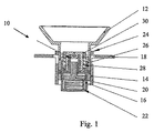
図1は本発明による装置10の断面概略図である。装置10は、本体14に結合された接合部材(インターフェイス)12を備えている。本体14は、液供給対象面、好ましくは人の目に供給される液を貯留する容器16を備えている。本体14は、該本体14から直交する方向に延設けされた円周壁18を有している。この円周壁18は、以下に説明するように、容器16内の液を液供給対象面に供給する際に、前記円周壁18を利用して装置を押し又は保持するために使用される。
FIG. 1 is a schematic cross-sectional view of an
容器16内にはピストン20が取り付けられている。このピストン20は、容器16から液を排出して液供給対象面内又は液供給対象面の表面に前記液を注ぐために、容器16内の液を加圧状態で貯留するようにばね22によって付勢されている。ピストン20は、ばね22と相互作用を行う基部と、容器16内に延びる延長部とを備えている。
A
別のばね24は、所定量の液を容器から人の目に供給した後に、接合部材12を確実に初期状態に戻すために備えられている。このばね24は、円周壁18と接合部材12の下端部とに当接する。
Another
本体14内には、容器16を取り囲む包囲体26が配置されており、該包囲体26は、液が継続して排出されるのを阻止し、1回の不逆性操作、好ましくは瞬時の操作により、容器16内から所定量の液が供給できるようにする。
An
包囲体26の作用は、以下の図面に関連して説明する。
The operation of the
追加のばね28は、容器16を接合部材12と一層密接な関係に持って来るために、容器16を引っ張っている。
An
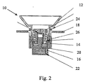
図2において、接合部材12は容器16に向けて押圧されており、それにより、小さな容積又はスペースが容器16とブロック30との間に確保されている。ブロック30は、液を放出するためのノズルを構成する窓又は開口を有している。本発明の好ましい実施形態においては、ブロック30のノズルは円筒形状になっている。しかし、他の実施形態として、別の形状、たとえば正方形、長方形、三角形又はその他の形状とすることもできる。さらに、複数のノズルをブロックに形成することも可能である。
In FIG. 2, the joining
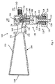
図3は接合部材12、包囲体26及び容器16の概略図である。図3に示されているように、包囲体26は突出部32を含んでおり、この突出部32は、初期状態において、接合部材12の対応する突出部34に当接している。突出部32は傾斜縁を有しており、接合部材12が包囲体26に向かって移動した時に、前記突出部32の傾斜縁の作用により、包囲体26が左側に回転しつつ、接合部材12側へさらに進むようになっている。これは、装置を使用する人が、急に、目に所定の量又は容積の液を供給する必要が生じた時に、たとえば半分の供給量で終わることなく、唯一、全供給量を人の目に供給できるように、装置を装填又は準備できるようになることを意味している。包囲体26はさらに複数の溝36又は軌道を有しており、一方、容器16には軌道又は突出部38が取り付けられ、又は一体に形成されており、前記複数の溝36と突出部38とが協働するようになっている。図4及び図5は、所定の施液量又は容量を放出する前の圧縮状態における装置10を示している。この状態において、ユーザーは、目に向いている接合部材12又は円周壁18を、包囲体の突出部32が、図5に示すように接合部材12の突出部34に殆ど接触しなくなるポイントまで押し下げている。
FIG. 3 is a schematic view of the joining
図4に示されているような装置10の状態では、ピストン20が、容器16に貯留されている液を、容器16内のスペース又は容積40内に押圧することができる。
In the state of the
包囲体26の溝36の作用により、包囲体26が接合部材12に対して相対的にねじられ又は回転され、それにより突出部32が接合部材12の突出部34から確実に滑って離れることができるようになっている。
Due to the action of the
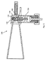
図6は、スペース40内に貯留された液が、ノズル42を通して供給又は放出され流状態の装置10を示している。流体又は液はノズル42を通して供給されるので、液は、霧状に分散又は変化して接合部材12の開口を通過する。これにより、装置を使用する人の目には噴霧が到達するので、噴霧によって人に対して如何なる不快感を与えることはないであろう。ノズルを出る時の液圧は、好ましくは0バールを越える圧力で、ノズルの入口で1バールである。図7に示す装置の状態は、室又は容積40から液が排出された後の状態である。図7に示すように、突出部32、34同士がこれ以上接触しないように包囲体26がねじられた結果、包囲体26は接合部材12に可能な限り接近している。
FIG. 6 shows the
図8は装置10の概略図を示しており、装置10が再度使用できる体制に戻るように、ばね24によって接合部材12は初期の状態に押し戻されている。
FIG. 8 shows a schematic view of the
図9は本発明の第2の実施の形態を示す概略図であり、装置は符号100で示している。この装置100は、2つの部材、たとえば供給部材102と接合部材104とから構成されている。供給部材102は貯留スペース108を有する本体106を備えている。貯留スペース108を画定する壁の一つは、ピストン110で構成されており、このピストン110は、ピストンヘッド112とピストンロッド114とを備えている。ピストンヘッド112にはシール部材116が嵌着されている。このシール部材116は、本発明の好ましい該実施の形態においては、プラスチック材からなる弾性リングで構成されている。
FIG. 9 is a schematic view showing a second embodiment of the present invention, and the apparatus is denoted by
液は貯留スペース108内に貯留さており、この液としては、水、塩水又は医療用化合物の溶液を使用することができる。
The liquid is stored in the
ばね118は、ピストンヘッド112を矢印120方向に付勢している。ばね118は、本体106の貯留スペース108の開口端を閉じているキャップ122に載置されている。キャップ122には、ピストンロッド114が延び出す窓孔124が形成されている。キャップ122及び本体106は、ピストンロッド114が供給部材102の外装を越えて延び出さないように形成することができる。
The
キャップ122は、本体106の外周に形成されたねじ128に螺合するねじ126を有している。
The
貯留スペース108と、液が供給されるノズル134を有するヘッド132とは、通路130により連通している。前記ヘッド132は、本体106の頂部に当接するばね136によって付勢されている。
The
接合部材104は、本体106がスライド自在に取り付けられるアーム138を有している。本体106は、操作中、アーム138上を矢印140方向にスライドする。図9は、始動位置の本体104の概略を示している。ばね142は、後述するように、本体106を矢印144方向に引っ張っている。
The joining
アーム138は傾斜カム146を有し、該傾斜カム146上をヘッド132がスライドするようになっているが、一方、本体106は矢印140方向にスライドする。傾斜カム146は平面部148を有している。
The
接合部材104は、図9に示す本発明の実施形態においては、2つの開口端部152及び154を有する裁頭円錐部材150により構成されている。本体106が、矢印140方向に開口端部152に向かって移動すると、流体は、貯留スペース108から、通路130の端部とヘッド132とで形成される中間スペースに移動する。本体106が終端位置に到達した時、霧状になった流体が、ノズル134及び開口端部152を通って放出され、それにより、霧状の流体は、接合部材104を通過し、人の目等の液供給対象面に供給される。この操作は、以下の図によりさらに詳しく説明される。
In the embodiment of the present invention shown in FIG. 9, the joining
図10は、図9に記載された装置100の拡大部分である。この図10は、装置100が初期又は始動位置に位置している時にヘッド132が通路130の端部に当接している状態を示している。ヘッド132は、更に、通路130から中間貯留室158へと通過する液が通過するための通路156を有し、該通路156を経てノズル134を通過するようになっている。
FIG. 10 is an enlarged portion of the
図11は装置100の概略図であり、該装置100が、通路130の端部においてヘッド132内の空隙160により形成された中間貯留室158から流体が放出される直前の状態を示している。
FIG. 11 is a schematic view of the
ばね136は、図9に示す位置に対して圧縮された状態となっている。
The
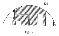
図12はヘッド132の拡大概略図であり、空隙160によって形成された中間貯留スペース158と、通路130を含む本体の上端とを示している。ヘッド132が上昇するに伴い、液がノズルに送られる前に一時的に貯留されるスペースが形成される。上記ノズルからは給液対象面に液が供給される。
FIG. 12 is an enlarged schematic view of the
図13は、中間室又は貯留スペース158から流体が吐出された後の状態の装置100の概略を示している。ヘッド132は、傾斜カム146の平坦部148の端部を通り過ぎ、ばね136が矢印162方向にヘッド132を押圧している。流体は、接合部材104の開口端部154に向かってノズル134内を矢印164の方向に通過している。
FIG. 13 shows an outline of the
装置100を使用している人が、装置100の握り状態を解除すると、ばね142が本体106を矢印144の方向に引っ張ることになる。本実施の形態では、アーム138は撓み自在となっており、本体が図9に示す初期又は始動位置に移動する時に、図13に示す位置にヘッド132を維持させた状態で、傾斜カム146の端部がヘッド132の外側壁を押すようになっている。
When a person using the
図14は、3本の通路166を有するノズル164の概略図である。流体は、ノズル164の外側から通路166を通ってノズル164の中央部の旋回室168内に流れる。ノズル164には、旋回室168の中央に孔170が形成されている。液体は、通路166を通って旋回室168内に流入し、幾何学的な形態によって、流体は旋回室168内で旋回を始め、孔170を通って旋回室168から噴出される。
FIG. 14 is a schematic view of a
図15は図14のノズル164の概略斜視図である。
FIG. 15 is a schematic perspective view of the
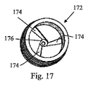
図16は3本の通路174を有するノズル172の第2の実施の形態を示す概略平面図である。図14に示された通路166は全て、通路166の全長に亘って略等しい断面形状を有している。一方、図16のノズル172の通路174は、中心に向かって減少する通路断面を有している。すなわち、通路174を通過する流体の速度及び又は流体圧が、通路174内を流れるに伴って増加し、加圧及び又は加速された状態で旋回室176に入り、孔178から外に噴出されるようになっている。
FIG. 16 is a schematic plan view showing a second embodiment of a
図17は、図16のノズル172の概略斜視図であり、図14及び図15に記載されたノズル164の旋回室168と比べ、異なった幾何学形態を有している。すなわち、図17の旋回室176は裁頭円錐形状に形成されており、これは、通路174から旋回室176を流れる流体又は液体の流れ方向に見て、旋回室176の直径が、減少するように形成されている。
FIG. 17 is a schematic perspective view of the
ノズル164及び172は、それぞれ本発明による装置に接続することができるノズルを例示したものである。これら2つのノズルは、ノズルの開口から噴出される流体又は液体を通過させるために3本の通路を備えている。通路の幅及び又は断面は、所望の液量や、ノズルから噴出される霧状の液の圧力及び速度によって、必要に応じ、変更することができる。
The
また、通路の数も、少量の液を吐出する場合には、単一の通路を備えるか、または、小さな直径の複数の通路を備えることにより、1回で噴出させる液の量を制限することができる。液が噴出される孔の直径も、図18で示すような所定の噴霧角度を得るための旋回室の形状と同様に、変更することができる。図18では、噴霧180は、破線で示されている。流体又は噴霧状の流体がノズル192から離れる時の噴霧角度186を寸法採りした実線188及び199との間で為す角度が、噴霧角度として定義することができる。
In addition, when a small amount of liquid is discharged, the number of passages should be limited to the amount of liquid ejected at one time by providing a single passage or a plurality of passages having a small diameter. Can do. The diameter of the hole through which the liquid is ejected can also be changed in the same manner as the shape of the swirl chamber for obtaining a predetermined spray angle as shown in FIG. In FIG. 18, the
各図は、本発明の各実施の形態を概略的に記載したものであり、各実施の形態の如何なる特徴もそれらを結合することが可能である。図示された各実施の形態は、本発明の範囲を制限するものではなく、本発明を説明するための例示に過ぎない。 Each drawing schematically describes each embodiment of the present invention, and any feature of each embodiment can be combined. The illustrated embodiments do not limit the scope of the present invention, but are merely examples for explaining the present invention.
本発明は、以下の述べるような各要点により特徴付けることができる。
第1の要点:
1.予め決められた量の液を繰り返し供給する装置において、
軸方向両端の第1の端部と第2の端部とを有すると共に、液を貯留するための内部スペースを有し、前記第1の端部に前記液が加圧力により通過する制限された開口が形成されている、円筒状本体と、
前記第2の端部から内部スペース内に延びる、プランジャと、
該プランジャに接続され、該プランジャを円筒状本体の第1の端部に向けて移動させる、ばねと、
人間の目に接合されて予め決められた量の液を上記目に供給する接合部材であって、前記制限された開口と流通可能に接続すると共に、柔軟で可撓性を有する材料で形成され、前記円筒状本体に沿って又は平行に延びる少なくとも一つの突起を含んでいる、接合部材と、
前記円筒状本体を幾何学的に取り囲むと共に、管状の幾何学形状を有し、前記接合部材の突出部に係合する一つの傾斜カム、又は複数の傾斜カムの一つを有する、円周包囲体と、を備え、
前記傾斜カムと前記突出部とは、前記包囲体の相対的な回転及び又は移動により、前記プランジャを一度に前記第1の端部に向けて移動させるように形成され、位置決めされている。
The present invention can be characterized by the following points.
First point:
1. In an apparatus for repeatedly supplying a predetermined amount of liquid,
It has a first end portion and a second end portion at both ends in the axial direction, and has an internal space for storing the liquid, and the liquid is restricted to pass through the first end portion by the applied pressure. A cylindrical body in which an opening is formed;
A plunger extending from the second end into an interior space;
A spring connected to the plunger and moving the plunger toward the first end of the cylindrical body;
A joining member that joins the human eye and supplies a predetermined amount of liquid to the eye, and is formed of a soft and flexible material that is connected to the restricted opening in a flowable manner. A joining member including at least one protrusion extending along or in parallel with the cylindrical body;
A circumferential enclosure that geometrically surrounds the cylindrical body and has a tubular geometry and has one inclined cam or one of a plurality of inclined cams that engages the protrusion of the joining member. With body,
The inclined cam and the protrusion are formed and positioned so as to move the plunger toward the first end at once by relative rotation and / or movement of the enclosure.
第2の要点:
2.前記第1の要点において、
前記円筒状本体は、さらに、前記容器から所定体積の前記液を受け入れて貯留する中間室を含んでおり、該中間室は、入口と出口とを有し、前記入口は前記容器と流通可能に接続し、前記出口は前記接合部材と流通可能に接続している。
Second point:
2. In the first point,
The cylindrical main body further includes an intermediate chamber that receives and stores a predetermined volume of the liquid from the container, the intermediate chamber having an inlet and an outlet, and the inlet can be circulated with the container. The outlet is connected to the joining member so as to be able to flow.
第3の要点:
3.前記第1又は第2の要点において、
前記所定体積は0.01乃至100mlである。たとえば、0.05乃至90ml、0.1乃至80ml、0.5乃至70ml、1乃至60ml、1.5乃至35ml、2乃至20ml、3乃至10ml、4乃至5ml、0.01乃至0.05ml、0.05乃至0.1ml、0.1乃至0.5ml、0.5乃至1ml、1乃至2ml、2乃至3ml、3乃至5ml、5乃至10ml、10乃至20ml、20乃至40ml、40乃至60ml、60乃至100mlである。
Third point:
3. In the first or second point,
The predetermined volume is 0.01 to 100 ml. For example, 0.05 to 90 ml, 0.1 to 80 ml, 0.5 to 70 ml, 1 to 60 ml, 1.5 to 35 ml, 2 to 20 ml, 3 to 10 ml, 4 to 5 ml, 0.01 to 0.05 ml, 0.05 to 0.1 ml, 0.1 to 0.5 ml, 0.5 to 1 ml, 1 to 2 ml, 2 to 3 ml, 3 to 5 ml, 5 to 10 ml, 10 to 20 ml, 20 to 40 ml, 40 to 60 ml, 60 to 100 ml.
第4の要点:
4.前記第1乃至第3の要点のいずれかにおいて、
前記接合部材は、人の目の輪郭に実質的に対応した形状のカップを有する開口端部構造によって構成されている。
Fourth point:
4). In any of the first to third points,
The said joining member is comprised by the opening edge part structure which has a cup of the shape substantially corresponding to the outline of a human eye.
第5の要点:
5.前記第1乃至第4の要点のいずれかにおいて、
前記供給部材は、シリコーンのような柔軟で可撓性を有する材料から作られた被覆部と、プラスチック材から作られた円錐部材と、から構成されている。
Fifth key point:
5. In any of the first to fourth points,
The supply member is composed of a covering portion made of a soft and flexible material such as silicone, and a conical member made of a plastic material.
第6の要点:
6.前記第1乃至第5の要点のいずれかにおいて、
前記接合部材又は被覆部は、人の目の涙管に接触してその涙管を実質的に閉じる突出部を有している。
Sixth point:
6). In any of the first to fifth points,
The joining member or covering portion has a protrusion that contacts the lacrimal duct of a human eye and substantially closes the lacrimal duct.
第7の要点:
7.前記第6の要点において、
前記突出部は、前記接合部材及び又は前記被覆部の滑らかで、及び又は連続的な拡大部で構成されている。
Seventh point:
7). In the sixth point,
The protruding portion is constituted by a smooth and / or continuous enlarged portion of the joining member and / or the covering portion.
第8の要点:
8.前記第6の要点において、
前記突出部は、前記供給部品及び又は被覆部に、非連続的に設けられた拡大部で構成されている。
Eighth point:
8). In the sixth point,
The projecting portion is constituted by an enlarged portion provided discontinuously on the supply component and / or the covering portion.
第9の要点:
9.前記第1乃至第8の要点のいずれかにおいて、
前記内部スペースは、0.01乃至100mlである。たとえば、2乃至75ml、5乃至50ml、10乃至35ml、20至25ml、0.1乃至0.5ml、5乃至15ml、15至25ml、25乃至35ml、35乃至45ml、45乃至65ml、65乃至85ml、85乃至100mlである。
Ninth point:
9. In any of the first to eighth points,
The internal space is 0.01 to 100 ml. For example, 2 to 75 ml, 5 to 50 ml, 10 to 35 ml, 20 to 25 ml, 0.1 to 0.5 ml, 5 to 15 ml, 15 to 25 ml, 25 to 35 ml, 35 to 45 ml, 45 to 65 ml, 65 to 85 ml, 85 to 100 ml.
Claims (19)
前記液貯留部に接続されて前記液貯留部からの液を受け入れる液入口を有すると共に、容積及び所定の最大容積を変更可能に有し、さらに、液出口を有する中間液貯留スペースと、
前記中間貯留部のスペースの出口に接続される液入口を有すると共に、給液対象面に液を供給するための液出口を有するノズルと、を備え、
単一の操作により、所定量の前記液を前記液貯留部から前記中間貯留部のスペースに移送するように構成されている液供給装置。 A liquid storage section having a space for storing liquid, a liquid supply opening, and a movable wall capable of reducing the space;
A liquid inlet connected to the liquid reservoir for receiving the liquid from the liquid reservoir, the volume and a predetermined maximum volume being changeable, and an intermediate liquid storage space having a liquid outlet;
A liquid inlet connected to the outlet of the space of the intermediate reservoir, and a nozzle having a liquid outlet for supplying liquid to the liquid supply target surface,
A liquid supply apparatus configured to transfer a predetermined amount of the liquid from the liquid storage section to the space of the intermediate storage section by a single operation.
Applications Claiming Priority (2)
| Application Number | Priority Date | Filing Date | Title |
|---|---|---|---|
| DKPA200500103 | 2005-01-20 | ||
| PCT/DK2006/000033 WO2006076922A1 (en) | 2005-01-20 | 2006-01-20 | Apparatus for dispension of liquid |
Publications (2)
| Publication Number | Publication Date |
|---|---|
| JP2008528072A true JP2008528072A (en) | 2008-07-31 |
| JP2008528072A5 JP2008528072A5 (en) | 2009-03-12 |
Family
ID=36130188
Family Applications (1)
| Application Number | Title | Priority Date | Filing Date |
|---|---|---|---|
| JP2007551547A Pending JP2008528072A (en) | 2005-01-20 | 2006-01-20 | Liquid supply device |
Country Status (4)
| Country | Link |
|---|---|
| US (1) | US20090043269A1 (en) |
| EP (1) | EP1853207A1 (en) |
| JP (1) | JP2008528072A (en) |
| WO (1) | WO2006076922A1 (en) |
Families Citing this family (5)
| Publication number | Priority date | Publication date | Assignee | Title |
|---|---|---|---|---|
| WO2008041177A2 (en) * | 2006-10-02 | 2008-04-10 | I-Shine Danmark Aps | A dispensing device and a method of using the device |
| IT1400109B1 (en) * | 2010-05-20 | 2013-05-17 | Tof S R L | EMERGENCY SAFETY SHOWER |
| US8702663B2 (en) * | 2011-10-17 | 2014-04-22 | Niagara Pharmaceuticals Inc. | Eyewash container |
| PT3099362T (en) | 2014-01-31 | 2018-12-04 | Eye Go As | A device for applying an ophthalmic fluid |
| CN108670801A (en) * | 2018-06-07 | 2018-10-19 | 朱茂华 | A kind of ophthalmic nursing facilitates fixed eye cleaning device |
Citations (1)
| Publication number | Priority date | Publication date | Assignee | Title |
|---|---|---|---|---|
| US3934585A (en) * | 1970-08-13 | 1976-01-27 | Maurice David M | Method and apparatus for application of eye drops |
Family Cites Families (22)
| Publication number | Priority date | Publication date | Assignee | Title |
|---|---|---|---|---|
| US3170462A (en) * | 1962-01-05 | 1965-02-23 | Merck & Co Inc | Aerosol ophthalmic device |
| US5037406A (en) * | 1988-06-20 | 1991-08-06 | Smith William L | Eyedrop applicator attachment |
| US5499768A (en) * | 1989-05-31 | 1996-03-19 | Ohkawara Kakohki Co., Ltd. | Spray nozzle unit |
| CN1045419C (en) * | 1993-05-05 | 1999-10-06 | 艾里希普费弗工程师有限公司 | Device for transferring media |
| US6033384A (en) * | 1997-12-18 | 2000-03-07 | Py; Daniel | One-way actuation release mechanism for a system for applying medicament |
| US5997518A (en) * | 1998-01-14 | 1999-12-07 | Laibovitz; Robert A. | Apparatus and method for delivery of small volumes of liquid |
| US6899289B2 (en) * | 1999-12-06 | 2005-05-31 | National Research Council Of Canada | Atomizing nozzle for fine spray and misting applications |
| US6413246B1 (en) * | 2000-05-18 | 2002-07-02 | John E. Harrold | Metered, mechanically propelled, liquid dispenser |
| US7331944B2 (en) * | 2000-10-23 | 2008-02-19 | Medical Instill Technologies, Inc. | Ophthalmic dispenser and associated method |
| US6758837B2 (en) * | 2001-02-08 | 2004-07-06 | Pharmacia Ab | Liquid delivery device and method of use thereof |
| US20020130202A1 (en) * | 2001-03-15 | 2002-09-19 | Kah Carl L. | Spray nozzle with adjustable arc spray elevation angle and flow |
| DE10133870A1 (en) * | 2001-07-12 | 2003-02-06 | Chris P Lohmann | Ophthalmic agent, use of EGF for the treatment of dry eye syndrome and insert for the administration of EGF to the eye |
| US7108204B2 (en) * | 2002-02-06 | 2006-09-19 | Thomas Les Johnson | Spray nozzle |
| US20090314216A1 (en) * | 2002-02-06 | 2009-12-24 | Arieh Jehuda Polak | Spray device |
| US20050261641A1 (en) * | 2002-09-26 | 2005-11-24 | Warchol Mark P | Method for ophthalmic administration of medicament |
| WO2004067386A2 (en) * | 2003-01-31 | 2004-08-12 | Nestec S.A. | Viscous food and beverage dispensing system |
| US20100222752A1 (en) * | 2003-05-20 | 2010-09-02 | Collins Jr James F | Ophthalmic fluid delivery system |
| US20050244469A1 (en) * | 2004-04-30 | 2005-11-03 | Allergan, Inc. | Extended therapeutic effect ocular implant treatments |
| US20090264845A1 (en) * | 2004-07-30 | 2009-10-22 | Mitsubishi Chemical | Absorbent composite and method for producing same, asorbent article and nozzle |
| US7846140B2 (en) * | 2004-11-30 | 2010-12-07 | James Hagele | Mini eye drop tip |
| GB0426429D0 (en) * | 2004-12-01 | 2005-01-05 | Incro Ltd | Nozzle arrangement and dispenser incorporating nozzle arrangement |
| US20060147853A1 (en) * | 2005-01-06 | 2006-07-06 | Lipp Charles W | Feed nozzle assembly and burner apparatus for gas/liquid reactions |
-
2006
- 2006-01-20 EP EP06701035A patent/EP1853207A1/en not_active Withdrawn
- 2006-01-20 JP JP2007551547A patent/JP2008528072A/en active Pending
- 2006-01-20 WO PCT/DK2006/000033 patent/WO2006076922A1/en active Application Filing
- 2006-01-20 US US11/814,156 patent/US20090043269A1/en not_active Abandoned
Patent Citations (1)
| Publication number | Priority date | Publication date | Assignee | Title |
|---|---|---|---|---|
| US3934585A (en) * | 1970-08-13 | 1976-01-27 | Maurice David M | Method and apparatus for application of eye drops |
Also Published As
| Publication number | Publication date |
|---|---|
| WO2006076922A1 (en) | 2006-07-27 |
| US20090043269A1 (en) | 2009-02-12 |
| EP1853207A1 (en) | 2007-11-14 |
| WO2006076922A9 (en) | 2006-09-14 |
Similar Documents
| Publication | Publication Date | Title |
|---|---|---|
| JP6827508B2 (en) | Equipment for applying ophthalmic fluids | |
| JP2907939B2 (en) | Subgingival drug applicator | |
| US8262592B1 (en) | Fluid dispenser | |
| JPH08510939A (en) | Drug administration device | |
| US20150005714A1 (en) | Nasal rinse tip | |
| JP2014532445A5 (en) | Applicator and applicator system | |
| EP3331479B1 (en) | A device for applying an ophthalmic fluid | |
| JP2008528072A (en) | Liquid supply device | |
| US20110009836A1 (en) | Pharmaceutical delivery device | |
| WO1998012511A2 (en) | Fluid dispenser | |
| US20060081726A1 (en) | Controlled drop dispensing tips for bottles | |
| US7077831B2 (en) | Ophthalmic fluid dispenser | |
| JP2002502289A (en) | Ophthalmic fluid applicator | |
| US5921444A (en) | Dispenser providing treatment surface engagement | |
| JP2006305347A (en) | New method for administering ophthalmic solution | |
| JPS6036009A (en) | Coating or scattering instrument for liquid beauty preparation | |
| JPH09248341A (en) | Chemical administration device for nostril | |
| JPH09248340A (en) | Chemical administration device for nostril |
Legal Events
| Date | Code | Title | Description |
|---|---|---|---|
| A521 | Written amendment |
Free format text: JAPANESE INTERMEDIATE CODE: A523 Effective date: 20090120 |
|
| A621 | Written request for application examination |
Free format text: JAPANESE INTERMEDIATE CODE: A621 Effective date: 20090120 |
|
| RD04 | Notification of resignation of power of attorney |
Free format text: JAPANESE INTERMEDIATE CODE: A7424 Effective date: 20091228 |
|
| A131 | Notification of reasons for refusal |
Free format text: JAPANESE INTERMEDIATE CODE: A131 Effective date: 20110118 |
|
| A02 | Decision of refusal |
Free format text: JAPANESE INTERMEDIATE CODE: A02 Effective date: 20110719 |