JP2008518719A - Medical soft grip connector - Google Patents
Medical soft grip connector Download PDFInfo
- Publication number
- JP2008518719A JP2008518719A JP2007540025A JP2007540025A JP2008518719A JP 2008518719 A JP2008518719 A JP 2008518719A JP 2007540025 A JP2007540025 A JP 2007540025A JP 2007540025 A JP2007540025 A JP 2007540025A JP 2008518719 A JP2008518719 A JP 2008518719A
- Authority
- JP
- Japan
- Prior art keywords
- housing
- connector
- sleeve
- flexible member
- valve
- Prior art date
- Legal status (The legal status is an assumption and is not a legal conclusion. Google has not performed a legal analysis and makes no representation as to the accuracy of the status listed.)
- Pending
Links
- 239000012530 fluid Substances 0.000 claims abstract description 79
- 238000011144 upstream manufacturing Methods 0.000 claims abstract description 47
- 238000004519 manufacturing process Methods 0.000 claims abstract description 10
- 239000000463 material Substances 0.000 claims description 45
- 238000000034 method Methods 0.000 claims description 39
- 238000007789 sealing Methods 0.000 claims description 18
- 230000007246 mechanism Effects 0.000 claims description 14
- 238000000465 moulding Methods 0.000 claims description 13
- 238000004891 communication Methods 0.000 claims description 8
- 229920002379 silicone rubber Polymers 0.000 claims description 8
- 239000004945 silicone rubber Substances 0.000 claims description 8
- 238000003780 insertion Methods 0.000 claims description 7
- 230000037431 insertion Effects 0.000 claims description 7
- 238000005304 joining Methods 0.000 claims description 4
- 239000003365 glass fiber Substances 0.000 claims description 3
- 229920000515 polycarbonate Polymers 0.000 claims description 3
- 239000004417 polycarbonate Substances 0.000 claims description 3
- 229920006230 thermoplastic polyester resin Polymers 0.000 claims description 3
- 238000004026 adhesive bonding Methods 0.000 claims 1
- 239000000853 adhesive Substances 0.000 description 17
- 230000001070 adhesive effect Effects 0.000 description 17
- 230000008569 process Effects 0.000 description 10
- 239000007788 liquid Substances 0.000 description 7
- 230000003014 reinforcing effect Effects 0.000 description 7
- 210000003811 finger Anatomy 0.000 description 6
- 230000002829 reductive effect Effects 0.000 description 6
- 230000037303 wrinkles Effects 0.000 description 6
- 210000004369 blood Anatomy 0.000 description 5
- 239000008280 blood Substances 0.000 description 5
- 230000036316 preload Effects 0.000 description 5
- 229920001296 polysiloxane Polymers 0.000 description 4
- 241000894006 Bacteria Species 0.000 description 3
- 230000007423 decrease Effects 0.000 description 3
- 238000009423 ventilation Methods 0.000 description 3
- 239000003054 catalyst Substances 0.000 description 2
- 238000004140 cleaning Methods 0.000 description 2
- 238000013461 design Methods 0.000 description 2
- 239000000645 desinfectant Substances 0.000 description 2
- 229920001971 elastomer Polymers 0.000 description 2
- BASFCYQUMIYNBI-UHFFFAOYSA-N platinum Chemical compound [Pt] BASFCYQUMIYNBI-UHFFFAOYSA-N 0.000 description 2
- 238000012546 transfer Methods 0.000 description 2
- XLYOFNOQVPJJNP-UHFFFAOYSA-N water Substances O XLYOFNOQVPJJNP-UHFFFAOYSA-N 0.000 description 2
- 238000003466 welding Methods 0.000 description 2
- SYJPAKDNFZLSMV-HYXAFXHYSA-N (Z)-2-methylpropanal oxime Chemical compound CC(C)\C=N/O SYJPAKDNFZLSMV-HYXAFXHYSA-N 0.000 description 1
- JOYRKODLDBILNP-UHFFFAOYSA-N Ethyl urethane Chemical compound CCOC(N)=O JOYRKODLDBILNP-UHFFFAOYSA-N 0.000 description 1
- 206010069803 Injury associated with device Diseases 0.000 description 1
- 230000002411 adverse Effects 0.000 description 1
- 230000004888 barrier function Effects 0.000 description 1
- 238000005452 bending Methods 0.000 description 1
- 230000009286 beneficial effect Effects 0.000 description 1
- 210000000601 blood cell Anatomy 0.000 description 1
- 239000000356 contaminant Substances 0.000 description 1
- 230000008602 contraction Effects 0.000 description 1
- 230000008878 coupling Effects 0.000 description 1
- 238000010168 coupling process Methods 0.000 description 1
- 238000005859 coupling reaction Methods 0.000 description 1
- 230000000249 desinfective effect Effects 0.000 description 1
- 235000013870 dimethyl polysiloxane Nutrition 0.000 description 1
- 239000004205 dimethyl polysiloxane Substances 0.000 description 1
- 230000003670 easy-to-clean Effects 0.000 description 1
- 230000000694 effects Effects 0.000 description 1
- 239000013536 elastomeric material Substances 0.000 description 1
- 238000007429 general method Methods 0.000 description 1
- 239000011521 glass Substances 0.000 description 1
- 238000001631 haemodialysis Methods 0.000 description 1
- 238000010438 heat treatment Methods 0.000 description 1
- 230000000322 hemodialysis Effects 0.000 description 1
- 238000007373 indentation Methods 0.000 description 1
- 238000001802 infusion Methods 0.000 description 1
- 239000007924 injection Substances 0.000 description 1
- 238000002347 injection Methods 0.000 description 1
- 208000014674 injury Diseases 0.000 description 1
- 230000002452 interceptive effect Effects 0.000 description 1
- 230000007794 irritation Effects 0.000 description 1
- 230000000670 limiting effect Effects 0.000 description 1
- 238000005297 material degradation process Methods 0.000 description 1
- 239000000203 mixture Substances 0.000 description 1
- 238000012986 modification Methods 0.000 description 1
- 230000004048 modification Effects 0.000 description 1
- 238000007911 parenteral administration Methods 0.000 description 1
- 230000002093 peripheral effect Effects 0.000 description 1
- 229910052697 platinum Inorganic materials 0.000 description 1
- 229920000435 poly(dimethylsiloxane) Polymers 0.000 description 1
- 230000001681 protective effect Effects 0.000 description 1
- 229920003051 synthetic elastomer Polymers 0.000 description 1
- 229920001187 thermosetting polymer Polymers 0.000 description 1
- 210000003813 thumb Anatomy 0.000 description 1
- 230000008733 trauma Effects 0.000 description 1
Images


Classifications
-
- A—HUMAN NECESSITIES
- A61—MEDICAL OR VETERINARY SCIENCE; HYGIENE
- A61M—DEVICES FOR INTRODUCING MEDIA INTO, OR ONTO, THE BODY; DEVICES FOR TRANSDUCING BODY MEDIA OR FOR TAKING MEDIA FROM THE BODY; DEVICES FOR PRODUCING OR ENDING SLEEP OR STUPOR
- A61M39/00—Tubes, tube connectors, tube couplings, valves, access sites or the like, specially adapted for medical use
- A61M39/10—Tube connectors; Tube couplings
-
- A—HUMAN NECESSITIES
- A61—MEDICAL OR VETERINARY SCIENCE; HYGIENE
- A61M—DEVICES FOR INTRODUCING MEDIA INTO, OR ONTO, THE BODY; DEVICES FOR TRANSDUCING BODY MEDIA OR FOR TAKING MEDIA FROM THE BODY; DEVICES FOR PRODUCING OR ENDING SLEEP OR STUPOR
- A61M39/00—Tubes, tube connectors, tube couplings, valves, access sites or the like, specially adapted for medical use
- A61M39/22—Valves or arrangement of valves
- A61M39/26—Valves closing automatically on disconnecting the line and opening on reconnection thereof
-
- A—HUMAN NECESSITIES
- A61—MEDICAL OR VETERINARY SCIENCE; HYGIENE
- A61M—DEVICES FOR INTRODUCING MEDIA INTO, OR ONTO, THE BODY; DEVICES FOR TRANSDUCING BODY MEDIA OR FOR TAKING MEDIA FROM THE BODY; DEVICES FOR PRODUCING OR ENDING SLEEP OR STUPOR
- A61M39/00—Tubes, tube connectors, tube couplings, valves, access sites or the like, specially adapted for medical use
- A61M39/22—Valves or arrangement of valves
- A61M39/26—Valves closing automatically on disconnecting the line and opening on reconnection thereof
- A61M2039/263—Valves closing automatically on disconnecting the line and opening on reconnection thereof where the fluid space within the valve is decreasing upon disconnection
-
- A—HUMAN NECESSITIES
- A61—MEDICAL OR VETERINARY SCIENCE; HYGIENE
- A61M—DEVICES FOR INTRODUCING MEDIA INTO, OR ONTO, THE BODY; DEVICES FOR TRANSDUCING BODY MEDIA OR FOR TAKING MEDIA FROM THE BODY; DEVICES FOR PRODUCING OR ENDING SLEEP OR STUPOR
- A61M39/00—Tubes, tube connectors, tube couplings, valves, access sites or the like, specially adapted for medical use
- A61M39/22—Valves or arrangement of valves
- A61M39/26—Valves closing automatically on disconnecting the line and opening on reconnection thereof
- A61M2039/266—Valves closing automatically on disconnecting the line and opening on reconnection thereof where the valve comprises venting channels, e.g. to insure better connection, to help decreasing the fluid space upon disconnection, or to help the fluid space to remain the same during disconnection
-
- A—HUMAN NECESSITIES
- A61—MEDICAL OR VETERINARY SCIENCE; HYGIENE
- A61M—DEVICES FOR INTRODUCING MEDIA INTO, OR ONTO, THE BODY; DEVICES FOR TRANSDUCING BODY MEDIA OR FOR TAKING MEDIA FROM THE BODY; DEVICES FOR PRODUCING OR ENDING SLEEP OR STUPOR
- A61M2205/00—General characteristics of the apparatus
- A61M2205/02—General characteristics of the apparatus characterised by a particular materials
-
- A—HUMAN NECESSITIES
- A61—MEDICAL OR VETERINARY SCIENCE; HYGIENE
- A61M—DEVICES FOR INTRODUCING MEDIA INTO, OR ONTO, THE BODY; DEVICES FOR TRANSDUCING BODY MEDIA OR FOR TAKING MEDIA FROM THE BODY; DEVICES FOR PRODUCING OR ENDING SLEEP OR STUPOR
- A61M2205/00—General characteristics of the apparatus
- A61M2205/58—Means for facilitating use, e.g. by people with impaired vision
- A61M2205/586—Ergonomic details therefor, e.g. specific ergonomics for left or right-handed users
-
- A—HUMAN NECESSITIES
- A61—MEDICAL OR VETERINARY SCIENCE; HYGIENE
- A61M—DEVICES FOR INTRODUCING MEDIA INTO, OR ONTO, THE BODY; DEVICES FOR TRANSDUCING BODY MEDIA OR FOR TAKING MEDIA FROM THE BODY; DEVICES FOR PRODUCING OR ENDING SLEEP OR STUPOR
- A61M39/00—Tubes, tube connectors, tube couplings, valves, access sites or the like, specially adapted for medical use
- A61M39/02—Access sites
- A61M39/04—Access sites having pierceable self-sealing members
- A61M39/045—Access sites having pierceable self-sealing members pre-slit to be pierced by blunt instrument
-
- Y—GENERAL TAGGING OF NEW TECHNOLOGICAL DEVELOPMENTS; GENERAL TAGGING OF CROSS-SECTIONAL TECHNOLOGIES SPANNING OVER SEVERAL SECTIONS OF THE IPC; TECHNICAL SUBJECTS COVERED BY FORMER USPC CROSS-REFERENCE ART COLLECTIONS [XRACs] AND DIGESTS
- Y10—TECHNICAL SUBJECTS COVERED BY FORMER USPC
- Y10T—TECHNICAL SUBJECTS COVERED BY FORMER US CLASSIFICATION
- Y10T29/00—Metal working
- Y10T29/49—Method of mechanical manufacture
- Y10T29/49826—Assembling or joining
Abstract
医療用ソフトグリップ・コネクタは、上流端部と、下流端部と、中央部分を通って延びる管腔とを有する、ハウジングを備える。可撓性部材は、スリーブ部分と一体形成されたバルブ部分を有する。このバルブ部分は、前記ハウジングの一部内に配置されていると共に、前記ハウジングの管腔を通る流体の流れを制御するように構成されている。前記スリーブは、裏返しにされて、前記ハウジングの外面の少なくとも一部を包む。ある実施形態では、把持部分は、前記バルブ部分と一体形成される。また、ある実施形態では、コネクタは、通常、注射器又はその他の医療機器がコネクタの上流端部から取り外されると、カテーテルの管腔に正圧が生じるように構成されている。医療用流体コネクタ製造方法は、通常、スリーブが延出しているバルブ部材を形成する工程と、バルブとスリーブとハウジングとを組み立てる工程とを含む。 The medical soft grip connector includes a housing having an upstream end, a downstream end, and a lumen extending through the central portion. The flexible member has a valve portion integrally formed with the sleeve portion. The valve portion is disposed within a portion of the housing and is configured to control fluid flow through the housing lumen. The sleeve is turned inside out and encloses at least a portion of the outer surface of the housing. In certain embodiments, the gripping portion is integrally formed with the valve portion. Also, in certain embodiments, the connector is typically configured such that positive pressure is created in the lumen of the catheter when a syringe or other medical device is removed from the upstream end of the connector. A medical fluid connector manufacturing method typically includes the steps of forming a valve member from which a sleeve extends and assembling the valve, sleeve and housing.
Description
関連出願の相互参照
本出願は、2004年11月5日に出願された米国仮特許出願第60/625,644号及び2005年2月18日に出願された米国仮特許出願第60/654,250号の利益を主張する。これらの仮特許出願の全体が、参照により本明細書中に組み込まれる。
CROSS-REFERENCE TO RELATED APPLICATIONS This application, 2004 November 5 filed US Provisional Patent Application No. 60 / 625,644 Patent and February 2005 US filed 18 Provisional Patent Application No. 60/654, Claim the profit of No. 250. The entirety of these provisional patent applications is incorporated herein by reference.
本明細書中に開示した発明は、広く、医療用コネクタの分野に関し、詳細には、医療用無針コネクタに関する。 The invention disclosed herein relates generally to the field of medical connectors, and more particularly to a medical needleless connector.
病院及び医療機関において、流体を非経口投与する処置には、患者へ又は患者から流体を選択的に移送しやすくするため、日常的にコネクタが使用されている。例えば、患者内に位置決めされた先端へと続くカテーテルにコネクタを取り付けて、また、1つ以上のチューブ及び医療器具に様々なコネクタを取り付けて、患者へ又は患者からの流体の流れを制御してもよい。 In hospitals and medical institutions, connectors are routinely used to facilitate the selective transfer of fluids to or from patients for parenteral administration of fluids. For example, attaching a connector to a catheter leading to a tip positioned within a patient, and attaching various connectors to one or more tubes and medical devices to control fluid flow to or from the patient. Also good.
一般的に、無針コネクタは、針の無い医療器具を選択的に接続することによって、患者と流体源若しくは流体容器との間に流体を流すことができるように構成されている。医療器具が取り外されると、このコネクタは閉鎖するため、患者に頻回注射を行う必要なく、また、医療専門家を不慮に針が刺さる危険に晒すことなく、患者に接続されたカテーテルを効果的に密閉することができる。このコネクタと共に用いられる医療器具は、チューブであってもよいし、その他の医療機器(例えば、導管、注射器、点滴セット(IV set)(周辺ラインと中央ラインとの両方)、ピギーバック・ライン(piggyback line)、又は、医療用バルブに接続するのに適した同様の構成要素)であってもよい。 Generally, needleless connectors are configured to allow fluid to flow between a patient and a fluid source or fluid container by selectively connecting a medical device without a needle. The connector closes when the medical device is removed, so that the catheter connected to the patient is effectively removed without the need for frequent injections into the patient and the risk of accidental needle sticks to the medical professional. Can be sealed. The medical device used with this connector may be a tube or other medical device (eg, conduit, syringe, IV set (both peripheral and central lines), piggyback line ( piggyback line) or similar components suitable for connection to medical valves.
多くの既存の医療用コネクタは、使用の際、医療専門家が比較的掴みにくい可能性がある。ほとんどの用途において、医療用コネクタは、製造コストを最小限に抑えるため、且つ、コネクタ内部の流体「死腔」(dead space)量を最小限に抑えるため、比較的小さく設計されている。更に、ほとんどの医療用コネクタは、外面が硬くて滑らかなハウジングを含んでいる。その結果、医療専門家は、医療処置の際に、繰り返し、コネクタを指できつく摘まんでしっかりと掴むこととなり、これは時に不快である。医療専門家は、患者を治療する際に、このようなコネクタを非常に頻繁に使用するので、コネクタをより効果的に掴むことができれば、コネクタを使用するのに必要な時間及び力が著しく改善され得る。更に、表面が硬い既存の医療用コネクタは、患者の肌にも不快である可能性がある。このような不快感は、医療用コネクタを使用して行う頻繁な治療(例えば、血液透析)を患者が必要とする場合、特に顕著となり得る。 Many existing medical connectors can be relatively difficult to grasp for use by medical professionals. In most applications, medical connectors are designed to be relatively small to minimize manufacturing costs and to minimize the amount of fluid “dead space” inside the connector. In addition, most medical connectors include a hard housing with a smooth outer surface. As a result, medical professionals will repeatedly pinch the connector tightly and hold it firmly during the medical procedure, which is sometimes uncomfortable. Medical professionals use such connectors very often when treating patients, so if they can be gripped more effectively, the time and force required to use the connectors will improve significantly. Can be done. Furthermore, existing medical connectors with a hard surface can be uncomfortable for the patient's skin. Such discomfort can be particularly noticeable when the patient requires frequent treatment (eg, hemodialysis) performed using a medical connector.
また、多くの既存の医療用コネクタは、様々な転向、屈曲、角を含む、複雑な流路によって、流体の流れを少なくとも部分的に妨害している。このような妨害によって、流速がかなり遅くなる可能性がある。また、このような妨害によって、血小板が損傷する可能性もある。 Many existing medical connectors also at least partially obstruct fluid flow with complex flow paths, including various turning, bending, and cornering. Such interference can cause the flow rate to be significantly slower. Such interference can also damage the platelets.
更に、多くの既存のコネクタでは、バルブからこれらの医療機器を外すと、流体がいくらか逆流してしまう。一般的に、これらのコネクタは内部空間を含み、流体は、医療器具からこの内部空間を通って、コネクタに取り付けられたカテーテルへと流れる。医療器具は、コネクタに取り付けられると、一般的に、この内部バルブ空間の一部を占有して、コネクタ内における一定量の流体を押しのける。医療器具が外されると、コネクタの内部空間からこの医療器具の部分が取り除かれることによって真空が生じ、このような空間を充填するため、流体が患者からラインを通ってコネクタの方へ引き上げられる傾向がある。 Furthermore, in many existing connectors, removing these medical devices from the valve will cause some backflow of fluid. In general, these connectors include an interior space, and fluid flows from the medical device through the interior space to a catheter attached to the connector. When a medical device is attached to a connector, it generally occupies a portion of this internal valve space and displaces a certain amount of fluid within the connector. When the medical device is removed, a vacuum is created by removing a portion of the medical device from the internal space of the connector, and fluid is pulled from the patient through the line to the connector to fill such space. Tend.
このように流体が逆流すると、いくつかの不都合が生じる。患者へと続く流体ラインにコネクタが取り付けられている場合、このラインを通ってコネクタ内の空間の方へ流体が逆流すると、患者からコネクタの方へ少量の血液が引き抜かれることとなる。このようにカテーテルに引き込まれた血液は、時間が経つと、カテーテルの先端付近を詰まらせることがあり、カテーテル先端の有効性を制限する恐れがある。 When the fluid flows back in this way, several disadvantages occur. If the connector is attached to a fluid line leading to the patient, a small amount of blood will be drawn from the patient toward the connector as fluid flows back through the line and toward the space in the connector. The blood drawn into the catheter in this way may clog the vicinity of the catheter tip over time, which may limit the effectiveness of the catheter tip.
カテーテルの内径が小さい場合には、血液がカテーテルの先端を詰まらせる可能性が高くなる。非経口用途では、このような内径が小さ目のカテーテルが、利点が多いために、頻繁に用いられる。例えば、内径が小さ目のカテーテルは、患者に挿入することにより生じる外傷及び不快感を軽減する。このようなカテーテルの管腔は小さいので、小さな吸引力でも、カテーテルを通してコネクタの方へ比較的長い距離にわたり流体を引き戻すことがある。 When the inner diameter of the catheter is small, there is a high possibility that blood will clog the tip of the catheter. In parenteral applications, such a small inner diameter catheter is frequently used due to its many advantages. For example, a smaller inner diameter catheter reduces the trauma and discomfort caused by insertion into a patient. Because the lumen of such a catheter is small, even a small suction force may draw fluid back over a relatively long distance through the catheter and toward the connector.
更に、いくつかの既存の医療用コネクタでは、コネクタの内側密閉部材と外側ハウジングとの間に隙間がある。このような隙間があることによって、細菌、残留物、又は消毒液が、開口部を通ってコネクタ内部へ入り、患者へ又は患者からの流体の流れに到達する恐れがある。 Further, in some existing medical connectors, there is a gap between the inner sealing member of the connector and the outer housing. Due to such gaps, bacteria, residues, or disinfectant can enter the connector through the opening and reach the fluid flow to or from the patient.
本発明のいくつかの実施形態によれば、上流端部と、下流端部と、中央部分を通って延びる管腔とを有するハウジング、及び可撓性部材を備える、医療用ソフトグリップ・コネクタが提供される。ある実施形態では、この可撓性部材は、把持部分と一体形成されたバルブ部分を有する。このバルブ部分は、前記ハウジングの一部内に配置されている。また、このバルブ部分は、前記ハウジングの管腔を通る流体の流れを制御するように構成されている。前記把持部分は、前記ハウジングの外面の少なくとも一部をカバーしている。 According to some embodiments of the present invention, a medical soft grip connector comprising a housing having an upstream end, a downstream end, and a lumen extending through the central portion, and a flexible member. Provided. In certain embodiments, the flexible member has a valve portion integrally formed with the grip portion. The valve portion is disposed within a portion of the housing. The valve portion is also configured to control fluid flow through the lumen of the housing. The grip portion covers at least a part of the outer surface of the housing.
ある実施形態では、医療用流体コネクタは、円筒体と、バルブ部分と、スリーブ部分とを備える。円筒体は、半径方向に延びる複数のフランジを備えた外壁と、一部を通って延びる管腔とを有する。バルブ部分は、前記円筒体の第1端部と第2端部との間を密閉する。スリーブ部分は、前記バルブ部分と一体形成され、前記円筒体の外面の大部分を囲み得る。 In certain embodiments, the medical fluid connector comprises a cylindrical body, a valve portion, and a sleeve portion. The cylindrical body has an outer wall with a plurality of radially extending flanges and a lumen extending through a portion. The valve portion seals between the first end and the second end of the cylindrical body. The sleeve portion may be integrally formed with the valve portion and may surround most of the outer surface of the cylindrical body.
また、医療機器の把持部分及び/又は密閉部分を形成する方法も提供される。ある実施形態では、この方法は、未硬化材料を型に注入することによって、ほぼ可撓性の材料から第1プレフォームを成型する工程を含む。このプレフォームは前記型から取り外され、第2プレフォームが成型される(必ずしも、第1プレフォームと同じ型でなくてよい)。次に、前記第1プレフォーム及び前記第2プレフォームが最終型に挿入され、未硬化材料が前記最終型に注入されて、前記第1プレフォーム及び前記第2プレフォームが、バルブ部材と該バルブ部材から延出するスリーブ部分とを有する最終構造にオーバーモールドされる。 Also provided is a method of forming a grasping portion and / or a sealing portion of a medical device. In certain embodiments, the method includes molding a first preform from a substantially flexible material by injecting uncured material into a mold. The preform is removed from the mold and the second preform is molded (not necessarily the same mold as the first preform). Next, the first preform and the second preform are inserted into a final mold, an uncured material is injected into the final mold, and the first preform and the second preform are connected to the valve member and the valve member. Overmolded to a final structure having a sleeve portion extending from the valve member.
また、医療用流体コネクタ製造方法も提供される。ある実施形態では、この方法は、バルブ部材と該バルブ部材から延出するスリーブとをほぼ可撓性の材料から一体形成する工程と、比較的剛性のハウジングを形成する工程とを含む。前記スリーブが前記ハウジングから延出するように、前記バルブ部材の一部が前記ハウジングのキャビティに挿入される。次に、前記スリーブが裏返しにされて、前記ハウジングの外面の少なくとも一部をカバーする若しくは囲む。 A medical fluid connector manufacturing method is also provided. In certain embodiments, the method includes integrally forming the valve member and a sleeve extending from the valve member from a substantially flexible material and forming a relatively rigid housing. A portion of the valve member is inserted into the cavity of the housing such that the sleeve extends from the housing. The sleeve is then turned over to cover or enclose at least a portion of the outer surface of the housing.
ソフトグリップ・コネクタの使用方法の実施形態では、下流端部は、第1医療器具(例えば、カテーテル)に接続される。このコネクタの上流端部における開口部には、第2医療器具が挿入される。ある実施形態では、第2医療器具がコネクタに導入されると、バルブ部材が拡張して内部容積が大きくなる。第2医療器具からの流体は、このバルブ部材へ流れ込む。ある実施形態では、このように流体が導入されると、バルブ部材の内部容積は更に拡張し、流体の流れが減少又は停止すると、バルブ部材の内部容積は収縮する。 In an embodiment of the method of using a soft grip connector, the downstream end is connected to a first medical device (eg, a catheter). A second medical instrument is inserted into the opening at the upstream end of the connector. In certain embodiments, when the second medical device is introduced into the connector, the valve member expands to increase the internal volume. Fluid from the second medical device flows into this valve member. In certain embodiments, when fluid is introduced in this manner, the internal volume of the valve member further expands, and when the fluid flow decreases or stops, the internal volume of the valve member contracts.
第2医療器具がコネクタから引き抜かれるときにも、バルブ部材の内部容積は小さくなる。ある実施形態では、バルブ部材は、元の状態(即ち、第2医療器具を挿入する前の状態)に素早く戻ることができる。バルブ部材内部の上流端部に近い領域は、下流端部に近い領域よりも狭くなっているため、上流方向への流体の流れは妨げられ、下流方向への流体の流れは促される。このようにして、コネクタ内部の流体は、コネクタの下流端部の方へ患者に向けて余儀なく流れ、これにより、正流効果がもたらされると共に、流体がバルブ内へ逆流するのを最小限に抑えることができる。正流バルブの様々な構造については、ICUメディカル社(ICU Medical, Inc.)保有の米国特許第6,695,817号及び米国特許出願公開第2004/0006330号に開示されており、このような文献は、その開示内容全体に関し、参照により本明細書中に組み込まれ、本明細書の一部を形成する。 The internal volume of the valve member also decreases when the second medical device is pulled out of the connector. In certain embodiments, the valve member can quickly return to its original state (ie, the state prior to insertion of the second medical device). Since the region near the upstream end in the valve member is narrower than the region near the downstream end, the flow of fluid in the upstream direction is hindered, and the flow of fluid in the downstream direction is promoted. In this way, fluid inside the connector is forced toward the patient toward the downstream end of the connector, thereby providing a positive flow effect and minimizing fluid backflow into the valve. be able to. Various structures of positive flow valves are disclosed in U.S. Patent No. 6,695,817 and U.S. Patent Application Publication No. 2004/0006330 held by ICU Medical, Inc. The literature is hereby incorporated by reference and forms part of this specification with respect to its entire disclosure.
多くの実施形態では、このコネクタは、小さいが掴みやすい。外側スリーブは、例えばシリコーンゴムからできていてもよく、このシリコーンゴムは、医療専門家がはめる標準的なゴム手袋に対して所望程度の滑り止め摩擦を発生させる。ある実施形態では、コネクタの上流端部に近い領域の外形は、可撓性の外側スリーブとバルブ部材とが一体形成されているため、ほぼ平滑でシームレスである。このような構造では、流体が患者へ向かって流れていく領域に細菌又はその他の残留物が溜まりにくく、このような領域をより容易に且つ効果的に消毒薬で拭くことができる。また、このようにバルブ部材と外側スリーブとが一体形成されることによって、製造工程が簡素化されると共にそのコスト効率が上昇する。 In many embodiments, the connector is small but easy to grasp. The outer sleeve may be made of, for example, silicone rubber, which produces the desired degree of non-slip friction against standard rubber gloves worn by medical professionals. In one embodiment, the outer shape of the region near the upstream end of the connector is substantially smooth and seamless because the flexible outer sleeve and valve member are integrally formed. In such a structure, bacteria or other residues are less likely to accumulate in areas where fluid flows toward the patient, and such areas can be more easily and effectively wiped with a disinfectant. In addition, since the valve member and the outer sleeve are integrally formed in this manner, the manufacturing process is simplified and the cost efficiency is increased.
このように本発明の特徴を要約すると、当業者には、添付の図面に関連した本明細書中の詳細な説明から、いくつかの好適な実施形態及びその変更形態が明らかになるであろう。 Summarizing the features of the present invention in this way, several preferred embodiments and modifications thereof will become apparent to those skilled in the art from the detailed description herein with reference to the accompanying drawings. .
次に、添付の図面を参照しながら、医療用ソフトグリップ・コネクタのいくつかの実施形態及び実施例を説明する。ソフトグリップ・コネクタのこれらの実施形態及び実施例は、正流バルブを備えたものとして図示及び説明するが、本明細書中に説明するシステム及び方法のいくつかの態様及び利点は、正流特性を持たないものを含むその他多数の流体コネクタ設計にも有益に適用することができる。 Several embodiments and examples of medical soft grip connectors will now be described with reference to the accompanying drawings. Although these embodiments and examples of soft grip connectors are shown and described as having a positive flow valve, some aspects and advantages of the systems and methods described herein are positive flow characteristics. It can be beneficially applied to many other fluid connector designs, including those without.
次に、図1を参照すると、医療用コネクタ10の図示されている実施形態は、実質的に剛性のハウジング12を備え、このハウジング12の外面上には、可撓性部材80が引き伸ばされてかぶせられていることにより、柔らかく掴みやすい外面22が形成されている。可撓性部材80の上流端部16には、スリット穴100が形成されている。ハウジング12を囲むこの可撓性部材80の上流端部は、洗浄しやすく、且つ、中に汚染物質が溜まり得るキャビティ若しくは凹部が実質的に無い、表面を形成している。図示されているように、この可撓性部材80の上流端部は、ハウジング12の全周囲を囲んでいるが、別の実施形態では、ハウジング12のほぼ全周囲又は一部(例えば、およそ4分の3、およそ2分の1、若しくはそれ以下)の周囲を囲むことも考えられる。別の実施形態では、可撓性部材80は、分割されて、ハウジング12の複数部分を囲んでもよい。例えば、この可撓性部材80には、その下にあるハウジング12の一部を露出するような1つ以上の穴若しくは穿孔が形成されていてもよいし、この可撓性部材80のハウジング12の外側にある部分が、ハウジング12に接触するようなストリップ若しくはバンドからできていてもよい。可撓性部材80の外面は、この可撓性部材80の内側部分(例えば、側方延長部84(以下で更に詳細に説明))をカバーして、使用の際にこのような内側部分が干渉されないようにすることができ、これにより、可撓性部材80の機能性がより堅実となる。
Referring now to FIG. 1, the illustrated embodiment of the
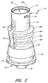
次に、図2〜図11を参照しながら、ハウジング12の実施形態について説明する。図2〜図6は、医療用ソフトグリップ・コネクタに用いられるハウジング12の一実施形態を示している。図7〜図11は、医療用ソフトグリップ・コネクタに用いられるハウジングの別の実施形態を示している。ここに開示した実施形態の1つの特徴を用いて又は複数の特徴を組み合わせて、その他多数の実施形態を形成してもよい。
Next, an embodiment of the
図2〜図6に示されているハウジングに関し、このハウジング12は、可撓性部材80を受容する上方キャビティ42と、コネクタを様々な医療機器に接合する接合部16及び30とを備える。通常、上方ハウジング40は円筒壁44を備え、この円筒壁44の対向する側部(例えば、互いに対して約180°の位置)には、長手方向溝46が設けられている。上方ハウジング40は、下端においてベース部材48と接合し、このベース部材48は、下方ルアー・コネクタ30(例えば、図5及び図6参照)を備える。消毒されたコネクタ10を保管したり輸送したりする際には、この下方ルアー・コネクタ30に保護キャップ(図示せず)を付けることによって、使用前の無菌状態を保つことができる。通常、このキャップは、下方ルアー・コネクタ30を医療器具に接続する直前に、医療専門家によって取り外される。
With respect to the housing shown in FIGS. 2-6, the
図示されているように、ハウジング部材12の実施形態は、複数のリング部60を更に含んでいてもよく、これらのリング部60は、上方ハウジング40の円筒壁44の外面から半径方向外側に延出する。ある実施形態では、これらのリング60は、頂部60aから底部60cに向けて直径が次第に小さくなっている。更に別の実施形態では、これらのリング60の数、サイズ、形状を、その他多数の方法で変更してもよい。
As shown, the
また、リング60と溝46との交差部に、フランジ62を設けてもよい。このフランジ62は、可撓性部材80の側方延長部84(例えば、図23参照)が、上方ハウジング40に挿入される際に、リング60が長手方向溝46によって二分されている地点におけるリング60の縁部にぶつかったり引っ掛かったりしないようにする。以下で更に詳細に説明するように、通常、これらのリング60及びフランジ62は、可撓性部材80のスリーブ20の一部を保持するように構成されている。
Further, a
図1、図5、及び図6に示されているように、直径が次第に小さくなっているリング60が截頭円錐形スカート52と連結されると、通常、ハウジングは「砂時計」形となる。有益なことに、これにより、コネクタはより掴みやすくなる。上方ハウジング40の下端に近い小径領域を、医療専門家の親指と人差し指とで掴むことができる。リング60の領域において、この小径領域の上下にある直径が次第に大きくなっている領域は、コネクタ10に対して他の医療器具を着脱する際に、人の指がコネクタ10の外面に沿って滑りにくくなるようにする。更に、スリーブ20の外面上における、医療提供者の指がコネクタ10を掴むと思われる領域に、他の把持面(例えば、バンプ、リッジ、その他のタイプの凹み又は突起)を設けてもよい。
As shown in FIGS. 1, 5, and 6, when a
ハウジング12は、コネクタをコンパクトにできる寸法であるのが好ましい。都合の良いことに、コンパクトなコネクタは、製造するのに必要な材料が比較的少量であるため、コストが比較的安い。更に、一般的には、コンパクトなコネクタは軽量であるため、比較的長時間にわたりコネクタを患者に付けて又は患者から下げて用いる場合、患者に対する刺激が緩和される。例えば、ある実施形態では、ハウジング12の上流端部16からルアー・カニューレ32の下流端部までの高さは、約0.400インチ〜1.200インチである。別の実施形態では、ハウジング12の高さは、約0.500インチ〜1.000インチである。更に別の実施形態では、この高さは、1.000インチ未満である。上方ハウジング40の上流端部16から下方ルアー・コネクタ30までの高さは、約0.500インチ〜0.750インチである。上方ハウジング40は、ハウジング12全体の高さのおよそ4分の3〜5分の4であるのが好ましい。ルアー・キャビティ74の高さは、ハウジング12の下端36からベース部材48の下面まで延びる。ある実施形態では、このルアー・キャビティの高さは、およそ0.150インチ〜0.350インチである。別の実施形態では、このルアー・キャビティの高さは、およそ0.400インチ未満である。また、ある実施形態では、このルアー・キャビティの高さは、およそ0.220インチである。ルアー・キャビティ74の高さは、ルアー・コネクタをぴったりと挿入することができるように、このルアー・キャビティ74に挿入されるルアー・コネクタの長さに対応しているのが好ましい。また、ルアー・キャビティ74の高さは、ハウジング12の高さのおよそ8分の1〜およそ3分の1であるのが好ましい。ある実施形態では、ルアー・カニューレ32は、ハウジング12の下端36よりも、およそ0.050インチ〜0.150インチ延出している。別の実施形態では、このルアー・カニューレ32は、下端36よりも、およそ0.80インチ〜0.120インチ延出している。また、ある実施形態では、このルアー・カニューレ32は、下端36よりも、およそ0.093インチ延出している。ルアー・カニューレは、ルアー・キャビティ74に挿入されるルアー・コネクタと連結するようなサイズ及び構成とされるのが好ましい。
The
以下で更に説明するように、リング60及びその他のハウジング構造の寸法は、スリーブ20の機構に対応する。例えば、ある実施形態では、円筒壁44の外径は、約0.200インチ〜約0.300インチ、好ましくは約0.250インチ〜約0.275インチであり、特定の一実施形態では、約0.265インチである。このような実施形態では、上方リング60aの高さ「h」(即ち、リングの外径と円筒形の上方ハウジングの外径との差)は約0.110インチ(±0.02インチ)であり、中間リング60bの高さは約0.093インチ(±0.02インチ)であり、下方リング60cの高さは約0.073インチ(±0.02インチ)である。従って、ある実施形態では、ハウジング12は、円筒壁44及びリング60a、60b、60cによって画定されると共に、最大直径が約0.310インチ〜0.410インチ、好ましくは約0.360インチ〜0.385インチ、特定の一実施形態では約0.375インチである、ほぼ砂時計形をした本体を含む。また、所望の特定用途に応じて、上記範囲内外のその他の寸法を用いてもよい。
As further described below, the dimensions of the
例えば、図1、図2、及び図5に示されているように、ハウジング12は、医療機器(例えば、注射器)の医療用ねじ付きコネクタ(例えば、ルアー・コネクタ)を受ける突起70(例えば、ラグ)を更に含んでいてもよい。図示されている実施形態では、この突起70ラグは、ほぼ長方形をしている。以下でより詳細に説明するように、このラグの縁部は、実質的に丸められたり面取りされたりしていてもよく、これにより、可撓性部材80のスリーブ20が、ハウジング12の外側に引き伸ばされてかぶせられた後、損傷するのを防ぐことができる。
For example, as shown in FIGS. 1, 2, and 5, the
スリーブ20は、突起70が可撓性部材80を通って突出するように構成されたウィンドウ126を含んでいてもよいが、このウィンドウ126は、スリーブ12が裏返しにされたとき(以下で更に詳細に説明)、突起70の周辺に密着係合するのが好ましい。別の実施形態では、突起70は、所望に応じ、その他の形状及び構成とされてもよい。ウィンドウ126の無いいくつかの実施形態では、突起70は、スリーブの厚みと連携して、コネクタ10の上流端部16に取り付けられるルアー・コネクタの雌ねじと係合することのできる突出部をスリーブに形成するようなサイズとされる。
The
ある実施形態では、ハウジングの下方接合部は、ルアー・コネクタ30を備えることにより、雌ねじ付きルアー・コネクタを備えた医療機器にコネクタ10を接合しやすくする。このハウジング12のルアー・コネクタ30は、ハウジング12の下端36から下方に延びる硬質のカニューレ32を備えることにより、他の医療機器(例えば、カテーテル・ハブ)と接続することができる。また、このルアー・コネクタ30の代わりに、その他の接合部及び結合部(例えば、ルアー滑り結合部、有刺ホース取付部など)を用いてもよい。
In certain embodiments, the lower joint of the housing includes a
図5及び図6に示されているように、ハウジングは、その上方キャビティ42内部へ延びる内側カニューレ50も含む。この内側カニューレ50は、ベース部材48及び下方ルアー・コネクタ30のルアー・カニューレ32を通って延びる管腔45を備える。下方ルアー・コネクタ30は、スカート52も含み、このスカート52は、ベース部材48から下方に延びていると共に、一般的には、雌ねじ56又はコネクタ10を他の医療機器に固定するその他の機構を備えている。このスカート52は、直径が上部から下部へより大きくなるように傾斜していてもよい。ある実施形態では、スカート52は、その下部周囲に環状の切込み溝54も含む。以下で更に詳細に説明するように、この環状溝54を用いて、スリーブの一部を保持することができる。
As shown in FIGS. 5 and 6, the housing also includes an
ある実施形態では、ハウジングの上方キャビティ40と、下方ルアー・スカート52によって画定されるキャビティ74との間に、通気孔72(図4参照)を設けるのが望ましい。通常、ハウジング12の外面は、最終アセンブリにおいてスリーブ20と接触するので(また、以下で医療用コネクタ10の組み立てに関して説明するように、ある実施形態では、スリーブ20は、ハウジング12の外面全体又はほぼ全体をカバーし得るので)、上方ハウジング40とキャビティ74との間におけるこのような通気は、空気、気体滅菌剤、又はその他の気体がハウジングの上方キャビティ内外へ自由に流れるようにするのに有用である。このような通気は、医療器具がコネクタ10のスリット穴100に挿入された場合、可撓性部材80が拡張し、可撓性部材80の外面と上方ハウジング40の内壁との間の容積が小さくなるので、特に有用である。また、これらの通気孔72は、水分及びその他の液体がハウジングの上方キャビティ内外へ自由に流れるようにしてもよく、これにより、多量の液体が上方ハウジング40内に溜まって可撓性部材80の拡張を制限する、或いは望ましくない細菌が増殖するのに快適な環境をもたらす、或いはその他の方法で医療用コネクタ10の動作に悪影響を及ぼす、というような危険性が減少する。通気が行われない場合、このように医療器具が挿入されると、抵抗が生じて、可撓性部材80に不都合な摩擦が起き、コネクタ10を使用するのに余計な力が必要となる。同様に、凹形通気孔76をルアー・スカート52の下端36に設けてもよく、これにより、コネクタ10が他の医療機器に取り付けられる際に、空気又はその他の気体がルアー・キャビティ74の内部から出て行くことができる。更に、これらの凹形通気孔76によって、他の医療機器が医療用コネクタ10から取り外される際に、空気又はその他の周囲気体がルアー・キャビティ74に入ることができ、これにより、医療機器が医療用コネクタ10に真空封止されることがない。また、これらの凹形通気孔76によって、医療用コネクタ10が他の医療機器に接続される際に、水、洗浄液若しくは消毒液、又はその他の液体がルアー・キャビティ74から出て行くことができる。ある実施形態では、スリーブ20自体に通気孔を設けることが望ましい。
In certain embodiments, it may be desirable to provide a vent 72 (see FIG. 4) between the
図7〜図11を参照すると、ある実施形態では、医療用ソフトグリップ・コネクタは、複数のハウジング部分から構成されたハウジングを備える。図示されている実施形態では、ハウジングは、第1ハウジング部分41及び第2ハウジング部分51から構成されている。図7は、2つの部品から成るハウジングの分解斜視図である。図8A及び図8Bは第1ハウジング部分41の斜視図であり、図9A及び図9Bは第2ハウジング部分51の斜視図である。
With reference to FIGS. 7-11, in one embodiment, a medical soft grip connector includes a housing comprised of a plurality of housing portions. In the illustrated embodiment, the housing comprises a
ある実施形態では、2つの部品から成るハウジングは、図2〜図6に示した上記ハウジングの構造的特徴の多く又は全てを含んでいてもよい。別の実施形態では、ハウジングは、3つ以上の部品を含んでいてもよい。図7〜図11に示されているこの2つの部品から成るハウジングは、医療機器(例えば、注射器)の医療用ねじ付きコネクタ(例えば、ルアー・コネクタ)を受ける突出ラグ71を含む。第1ハウジング部分41は、互いに対しておよそ180°の方向にある長手方向溝49も含む。ある実施形態では、異なる数の溝若しくはリッジを設けてもよく、これらの溝若しくはリッジは、どのようなサイズであってもよいし、どのような位置にあってもよい。この第1ハウジング部分41は、可撓性部材80を受容する上方キャビティ43を画定する。第2ハウジング部分51は、ねじ付きルアー・キャビティ59を含む。更に、第2ハウジング部分は、このルアー・キャビティ59の下面に凹形通気孔77を含んでいてもよい。また、第2ハウジング部分は、内側カニューレ53を含み、この内側カニューレ53は、第2ハウジング部分51を通って延びる管腔55を備える。更に、第2ハウジング部分は、第1ハウジング部分41とこの第2ハウジング部分51との間に、通気孔57を含んでいてもよい。また、この2つの部品から成るハウジングの寸法を、図2〜図6に示した1つの部品から成るハウジング12の実施形態に関して上述した範囲に対応させることも考えられる。従って、医療用コネクタのいくつかの実施形態では、2つの部品から成るハウジングを、1つの部品から成るハウジングと交換可能に使用することができる。
In some embodiments, a two-part housing may include many or all of the structural features of the housing shown in FIGS. In another embodiment, the housing may include more than two parts. The two-part housing shown in FIGS. 7-11 includes a protruding
図7〜図11に示されている2つの部品から成るハウジングは、更なる機構を含んでいてもよい。例えば、この2つの部品から成るハウジングは、第1ハウジング部分41と第2ハウジング部分51とを完全なハウジングに組み立てやすくする、様々な位置合わせ及び連結機構を含んでいてもよい。位置合わせのため、第2ハウジング部分は少なくとも1つのリッジ65を含み、第1ハウジング部分はこれに対応する少なくとも1つの凹部63を含み得る。図7に示されているように、これらのリッジ65及び側壁63は、ハウジングを組み立てる際に第1ハウジング部分41と第2ハウジング部分51とを所望の方向に位置合わせするように構成されている。ハウジングを連結方向に保持するため、第1ハウジング部分41は、少なくとも1つのタブ89を含み、第2ハウジング部分51は、このタブ89を受容するように構成された少なくとも1つの凹部85を含む。図示されているように、タブ89は、導入面及び干渉面を含む楔形をしており、導入面はタブ89を凹部に挿入しやすくすると共に、干渉面はタブ89が凹部85から抜けないようにする。本出願では特定の構造に関して説明及び図示したが、その他の位置合わせ及び連結機構を用いて2つのハウジング部分41及び51を連結することも考えられる。
The two-part housing shown in FIGS. 7-11 may include additional mechanisms. For example, the two-part housing may include various alignment and coupling mechanisms that facilitate assembly of the
図7〜図11に示されているハウジングでは、第1ハウジング部分41と第2ハウジング部分51とを組み合わせると、これらの間に空間61ができる。都合の良いことに、この空間61は、可撓性部材81の一端を保持するようなサイズ及び構成とされ得る。従って、このような構造では、ハウジングをその上にかぶせられる可撓性部材80に対して滑りにくくするために、2つの部品から成るハウジングに1つの部品から成るハウジング12(図2〜図6)で用いたリング60を設ける必要がない。可撓性部材80をハウジングに対して更に滑りにくくするために、第1ハウジング部分のラグ71に隣接した領域に凹部73を設けて接着剤を入れ、可撓性部材80をハウジングに接着してもよい。これらの接着剤とハウジングの材料は、適合するように選択されるべきである。例えば、ガラス繊維強化熱可塑性ポリエステル樹脂製ハウジングをシリコーンゴム製スリーブ20に接着するには、シリコーンベースの接着剤が適用され得る。図7〜図11に示されている2つの部品から成るハウジングは、上記のように滑りにくい上、より複雑で1つの部品から成るハウジングを製造するのに必要な1つの2工程成型処理ではなく、2つ別々の1工程成型処理で、速く且つ安く製造することができる。
In the housing shown in FIGS. 7 to 11, when the
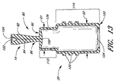
図12〜図14に示されているように、ある実施形態では、可撓性部材80において、バルブ部材14とスリーブ20とが一体形成されている。この可撓性部材80は、細部を強調するため、ハウジング12から取り外された状態で図示されている。バルブ部材14のいくつかの実施形態は、密閉体82を有し、この密閉体82は、一方向が相対的に薄く他方向が相対的に幅広いスラブ状構造をしていてもよい。バルブ部材14は、コネクタを選択的に密閉するように構成されている。この「密閉」という語は、本明細書中では便宜上、流体の流れを妨げることのできる構造を指すのに用いられているが、このような構造が、単独で又はその他の構造と組み合わせて、流体の流れを全く通さない障壁を形成する、ということを必ずしも示さない。ある実施形態では、密閉体82は、それから側方に延びる側方延長部84を備える。また、この密閉体82は、平坦でほぼ長方形のネック86及び横断フランジ90を更に備えていてもよい。ある実施形態では、スリーブ20は、フランジ90と一体形成され、軸方向において密閉体82から離れるように延びる。
As shown in FIGS. 12 to 14, in one embodiment, in the
ネック86は、第1側方延長部及び第2側方延長部84の間に位置しており、これらの側方延長部はそれぞれ、そのフランジ90に最も近い部分を構成するショルダー92を有する。従って、密閉体82、ネック86、フランジ90、及びスリーブ20は、一体式ユニットを形成することができる。通常、密閉体82は、それを通って延びる細い通路若しくはスリット94を含むように構成される。通常、このスリット94は、ネック86及びフランジ90を含む密閉体82を通って延びる。図14において、図面の縦断面はスリット94の垂直面に一致しており、この方向では、スリット94の下流端部における横幅が広くなっていることが分かる。また、このスリット94は、傾斜側部95及びより細いネック97も含む。図13は、図14の断面に直交する断面において、スリット94が細いことを明示している。
The
以下でより十分に説明するように、バルブ部材14は、ハウジング12のキャビティ42に挿入される。スリット94は、通常、その中に注射器又はその他の医療機器のカニューレを挿入することができるようなサイズ及び形状とされる。コネクタは、ANSI規格に基づいた注射器のルアー先端を受容するように構成され得る。ある実施形態では、スリット94は、バルブがより正流特性を示すように構成される。
As described more fully below, the
スリット94は、フランジ90におけるスリット穴100から、密閉体82のフランジ90とは反対側の下流端部に形成されたリード管腔102まで延びる。ある実施形態では、リード管腔102は、ほぼ円筒形であって、バルブ部材14の長手方向軸にほぼ平行な軸又はこの長手方向軸と同一直線上にある軸を中心とする。また、このリード管腔102には、ハウジング12の内側カニューレ50にかぶせやすくするように、且つ、可撓性部材80がかぶせられた後に流体の流れの断面積が小さくなり過ぎないように構成された、外径拡張部104(例えば、図14参照)を設けてもよい。
The
図13に示されているように、スリット94のいくつかの実施形態は、ほぼ平面状であって、そのままの状態(即ち、バルブ部材14に注射器カニューレが挿入されていない場合)では非常に細い。従って、このスリット94は、スリット穴100からリード管腔102まで、選択的に制限される流体経路を形成する。このような流路により、患者の治療における様々な標準流体圧条件下で、流体が可撓性部材80を全く通過しないか、或いは、臨床的に無視してもよい極少量だけ通過するのが好ましい。
As shown in FIG. 13, some embodiments of the
通常、このスリット94は、スリット穴100とリード管腔102との間に密閉可能な流体経路を形成するように構成されている。ある実施形態では、このスリット94は、本出願で図示及び説明されているように構成されてもよいし、参照により本明細書中に組み込まれるあらゆる特許及び特許出願で図示及び説明されているように構成されてもよい。一般的に、このスリット94は、その隣接面間に本質的には空間が無いように作られる。適切な密閉方法の例については、以下で更に詳細に説明する。
Normally, the
図12に示されている実施形態では、側方延長部84は、通常、多角形の角張った形状をしているが、特定の設計目標を考慮して、その他の適切な形状を用いてもよい。通常、この側方延長部84は、ハウジング12の一部と相互作用してバルブ部材14をハウジング12内に所望の向きで保持する構造を提供するように構成されている。図12に示されているように、この側方延長部84の平面に窪み110を形成してもよい。別の実施形態では、バルブ部材14の他の面に窪み110を形成してもよいし、更に別の実施形態では、バルブ部材14に窪み110を形成しなくてもよい。この窪み110を用いることによって、以下で更に説明するように、コネクタを成型して組み立てる際に、バルブ部材14を保持して側方延長部84を位置決めすることができる。
In the embodiment shown in FIG. 12, the
図13及び図14の実施形態では、スリーブ20は、バルブ部材14の横断フランジ90から可撓性部材80の反対側の端部まで軸方向に延びる。このスリーブ20は、横断フランジ90の直径にほぼ一致する第1直径D1を有する第1部分112と、第1直径D1よりもわずかに大きい第2直径D2を有する第2部分114とから構成され得る。ある実施形態では、第1直径D1を有する第1部分112の長さは、ハウジング12の上流端部16と上方リング60aとの間の距離にほぼ等しい。一般的に、スリーブ20の第2部分114は、その直径が砂時計形ハウジングの最も細い部分の直径とほぼ同じか或いはわずかに小さなサイズとされている。従って、スリーブ20は、裏返しに引き伸ばされてハウジング12の周囲にかぶせられた場合、ハウジング12のほぼ全長に沿って、その外面に密着するのが好ましい。
In the embodiment of FIGS. 13 and 14, the
ハウジング12周囲の裏返し位置に保持するため、スリーブ20に、ハウジング12の一部と係合する保持構造を設けてもよい。このような保持構造としては、例えば、突起、リブ、リッジ、狭窄部のような、様々な構造が挙げられる。図12〜図14に示されている実施形態では、スリーブ20は、複数の突起120を備える。別の実施形態では、これらの突起の代わりに、連続的な環状リブを用いてもよい。このような環状リブは、スリーブが裏返しにされるときに歪みやすいため、最終的に組み立てられたデバイスの外面に、波しわや凹凸ができてしまうことがある。従って、多くの実施形態では、図12に示されているような突起120の列を用いて、スリーブ20がより滑らかにハウジング12の外面上に位置するようにする。通常、これらの列は、スリーブ20が裏返しにされるときに、スリーブ20を変形させることなく、隣接した突起同士が互いに当接するように構成されている。これらの突起120はそれぞれ、例えば、長方形、円形、及び/又は楕円形のような、いろいろな形状をしていてもよい。
In order to hold in an inverted position around the
これらの突起120は、通常、ハウジング12のリング60間の空間に対応するように構成された環状列で設けられ得る。通常、各列の長さも、溝46に隣接した線形フランジ62間にこれらの突起が収まるようなサイズとされる。別の実施形態では、スリーブの突起120並びに/又はハウジング12のリング60及びフランジ62は、ハウジング12に対する軸方向の運動及び/又は回転運動に対抗してスリーブ20が保持されるような連携構造であれば、どのようなパターンで設けられてもよい。例えば、ある実施形態では、スリーブ20は、ハウジングの一部(例えば、ルアー突起70(図1参照))を受容して囲む凹部若しくはウィンドウ126を更に備える。別の実施形態では、図7〜図11の2つの部品から成るハウジングに関して上述したように、ハウジングにリング60が無いので、可撓性部材にも突起が無くてよい(図16〜図18参照)。
These
図示されている実施形態では、スリーブ20は、その開口部124周囲にある狭窄部122を備える。通常、この狭窄部122は、スリーブの第2部分114よりも直径が小さい部分から成る。また、この狭窄部122は、スリーブ20が裏返しにハウジング12上にかぶせられたとき、環状溝54(例えば、図24及び図25参照)のような、ハウジング12の機構と係合するように構成され得る。別の実施形態では、この狭窄部122は、第1ハウジング部分41と第2ハウジング部分51との間にある空間61(図10及び図11参照)と係合して保持されるように構成されてもよい。
In the illustrated embodiment, the
前述したように、スリーブ20のいくつかの実施形態は、突起70(ルアー・ラグとも言う)のようなハウジングの1つ以上の構造を収容して囲む、或いは、標準ルアー・コネクタを受容するようなサイズとされた、1つ以上のウィンドウ126を備えていてもよい。このような実施形態では、ウィンドウ126は、組み立て又は使用の際にスリーブ材料が不都合に破れるのを防ぐため、厚めの縁部を含むように成型されてもよい。
As previously described, some embodiments of the
更に、前述したように、ある実施形態では、スリーブ20は、バルブ部材14と一体形成されない。また、スリーブ20は、(別個に形成されたスリーブ部材を機械で引き伸ばしてハウジング12の外面上にかぶせるのではなく、)適切な把持領域をハウジング12の外面に付着させるか、コーティングするか、或いはその他の方法で設けることにより、形成されてもよい。また、スリーブ20は、医療提供者の指が掴むと思われるハウジング12の部分の周囲のみに延びる、バンド又はクリップとして形成されてもよい。また、ある実施形態では、コネクタ10は、スリーブ20を含まずに構成されてもよい。
Further, as described above, in some embodiments, the
図16〜図18に示されている実施形態では、可撓性部材81は、少なくとも1つの補強リブ87を含み、この補強リブ87は、バルブ部材14のほぼ長手方向軸に沿って配向されていると共に、側方延長部84の平面を横断するように突出している。図16は、2つの補強リブ87を含む可撓性部材81の様々な実施形態の斜視図であり、図17及び図18は、図16の可撓性部材81の断面図である。図示されている実施形態では、可撓性部材81は、突起120(図12〜図14参照)を含んでいないので、リング60の無いハウジングと組み合わせるように構成されている。別の実施形態では、可撓性部材は、補強リブ87と突起120との両方を含んで、図2に示されているようなリング60を有するハウジングに適用されてもよい。
In the embodiment shown in FIGS. 16-18, the
この補強リブ87によって、バルブ部材14に弾性及び耐久性をもたらすことができる。ある実施形態では、このリブ87は、医療器具がスリット穴100に挿入される際に、バルブ部材14がほぼ長手方向においてしわにならないようにするのを助けることができる。このようなしわは、流体の流れを妨害若しくは制限したり、コネクタの閉鎖を妨げたり、或いは、その他の点でいくらか不適切な動作を起こす可能性がある。医療用コネクタが劣化したり使用サイクルが繰り返されることで、このようなしわは更にできやすくなるので、補強リブは、医療用コネクタにおけるバルブ部材14の寿命を大いに延ばすことができる。ある実施形態では、補強リブ87と組み合わせて或いは補強リブ87の代わりに、医療用コネクタ10に更なる構造及び/又は材料を用いて、バルブ部材14がしわにならないようにしてもよい。例えば、バルブ部材14は、医療器具をスリット穴100に挿入することができる程度に可撓性である一方で、使用サイクルを繰り返してもしわにならない程度に剛性であるように選択された材料から構成され得る。同様に、バルブ部材14の所望の厚さを選択することにより、可撓性とバルブ寿命との所望のバランス及びしわ耐性が得られる。(バルブ部材14に厚い材料を用いるほど、可撓性が低下し医療器具がスリット穴100に挿入しにくくなる代わりに、バルブ寿命が延びしわ耐性が高くなる。)例えば、ある実施形態では、バルブ部材14の外側表面積の大部分、又はほぼ全部、又は全部にわたる壁部の厚さを、バルブ部材14と補強リブ87とを合わせた壁部の厚さとほぼ同じにしてもよい。ある実施形態では、バルブ部材14の壁部の厚さは、少なくともいくらかの領域において、リード管腔102の直径と少なくとも同じ大きさであるか、又は、リード管腔102の直径の少なくとも約1.5〜2倍の大きさである。
The reinforcing
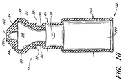
バルブ部材の使用寿命を延ばすように構成された、医療用ソフトグリップ・コネクタに用いられる別の実施形態である可撓性部材83が、図19〜図21に示されている。図19は、可撓性部材83の斜視図である。図19に示されているように、この可撓性部材83は、前述したような他の実施形態である可撓性部材80及び81と同じ外的特徴を多く備えていてもよい(図19〜図21に示されている特徴を含むが、これらに限定されない)。例えば、可撓性部材83は、バルブ部材153及びスリーブ165を含む。ある実施形態では、スリーブ165は、ハウジングの対応するフランジと結合する突起157を含む。また、このスリーブ165は、開口部163周囲にある狭窄部161を含む。また、このスリーブは、ハウジング上にある1つ以上の突起70又はその他の構造を収容して囲む、1つ以上のウィンドウ159を含んでいてもよい。この可撓性部材は、横断フランジ155、ネック167、及び側方延長部169を含む。図20及び図21に示されているように、この可撓性部材83は、下流開口部151を有するリード管腔173を含む。
Another embodiment of a
図19の可撓性部材83の断面図である図20及び図21に示されているように、図19〜図21に示されている可撓性部材83の実施形態の内部構造は、本出願で図示された他の実施形態である可撓性部材80及び81には無い機構を含む。この可撓性部材のバルブ部材153は、1組の対向する側壁177及び179を備え、これらの側壁177及び179は、バルブ部材153の上流端部で交差して、医療器具が挿入されるように構成されたスリット171を形成する。そのままの状態では、スリット171は、医療機器を密閉して、流体が通過しないようにする。下流方向において、側壁177及び179は分岐しており、そのままの状態では、バルブ部材によって画定される通路175の容積はノンゼロ(nonzero)である。従って、この可撓性部材83は、前述した可撓性部材80及び81の実施形態とは異なり、そのままの状態ではほぼ平面状である通路を有していない。
As shown in FIGS. 20 and 21, which are cross-sectional views of the
ある実施形態では、そのままの状態で容積がノンゼロであるこのような通路175は、スリット171に完全に挿入された医療器具が特定の状況下で取り外された場合、可撓性部材83の図示されている実施形態が正流特性を示さないようにすることができる。また、このような通路175の構造には、他にもいくつかの利点がある。この可撓性部材83には、前記のようなしわ耐性がある。このような分岐している側壁177及び179は、他の可撓性部材80及び81の実施形態の平面状側壁に比べて、バルブ部材153の耐久性を高める。
In some embodiments, such a
更に、可撓性部材83のスリット171は、側壁177と側壁179との接触領域が比較的小さい。このように接触領域が小さいと、それに対応して、そのままの状態における流れ抵抗も小さくなる。従って、医療器具を通路に部分的に挿入するだけで、或いは、医療器具をスリット171の中にではなく単に付近に配置するだけでも、バルブ部材に流体を素早く流し始めることができる。このように、医療器具の先端か或いは流体の流れ圧力が、スリット171における側壁177と側壁179との接触を断ち、バルブを開放する。有益なことには、そのままの状態における通路175の内部容積は、医療器具を部分的に挿入した状態における通路175の内部容積よりも小さいので、医療器具を通路に部分的に挿入するか或いは単に通路付近に接触させると、バルブ部材153は正流特性を示す。
Further, the
更に、図示されている可撓性部材83のように、医療器具が完全に挿入されたときに正流特性を示すように通路175が構成されていない場合、可撓性部材83の通路175は、相対的に幅の広い領域を含んでいなくてもよい。従って、可撓性部材83の通路175及び側方延長部169を、相対的に細くすることができる。これに応じて、正流特性を備えた医療用コネクタに比べ、ハウジングの直径を相対的に小さくすることができる。ゆえに、正流特性を備えない可撓性部材83の実施形態によれば、材料コストを削減しコネクタ重量を減少させることができる。
Further, if the
次に、図12〜図18を参照しながら、可撓性コネクタ80及び81のバルブ部材14の製造方法の実施形態について説明する。通常、本システムに用いられるバルブ部材14は、当業者が用いることのできる適切な方法であれば、どのような方法で製造されてもよい。ある有益な実施形態では、バルブ部材14は、第1及び第2「プレフォーム」130を成型し、次にこれらを向かい合わせにして第2の型に入れることにより、製造される。次に、これらのプレフォーム130は、別の成型処理でオーバーモールドされ、これにより、本出願で図示及び説明したようなバルブ部材14部分とスリーブ20部分とが一体化した可撓性部材80が形成される。
Next, an embodiment of a method for manufacturing the
一実施形態では、バルブ部材14は、米国特許出願公開第2004/0006330号に記載の一般的な方法により成型され得る。まず、1組のプレフォームを、第1組の型及び第2組の型の間で成型する。このような最初の成型工程の後、プレフォームが入ったままの片側の型同士を、それらの間にオーバーモールド板を挟んで合わせてプレスする。このオーバーモールド板は、通常、バルブ部材14の最終形状を形成するように構成されている。成型装置(プレフォーム型の片側同士及びオーバーモールド板を含む)が完全に組み立てられた状態で、次に、この成型装置に更なる未硬化材料を注入し、オーバーモールド板によってできた型キャビティの更なる空間を充填することにより、バルブ部材14の残りの部分を形成する。ある実施形態では、前記米国特許出願公開第2004/0006330号に記載のオーバーモールド方法を、本明細書中で説明したようなスリーブが一体化したバルブ部材14を形成するように適応させてもよい。或いは、バルブ部材14をこの米国特許出願公開第2004/0006330号の方法により成型した後に、例えば、成型、溶接、接着剤のような、あらゆる適切な方法で、このバルブ部材14にスリーブ20を接合してもよい。
In one embodiment, the
図15を参照しながら、オーバーモールド方法の別の実施形態を提供する。この方法によれば、プレフォーム130は、成型され、型から完全に取り外されてから、オーバーモールド工程又は接合工程が行われる。図15は、バルブ部材14を形成するのに用いられるプレフォーム130の一実施形態を示している。各プレフォーム130は、ほぼ平らな面132を有し、この面132は、完成したバルブ部材14において、スリット94の壁部を形成する。フランジ部分134も、各プレフォーム132と一体成型される。このフランジ部分134の側部を、平らな部分から成る面132から裏側へ設けることにより、オーバーモールド材料が2つのプレフォーム130のフランジ部分134間を流れてこれらを結合する空間136ができる。一般的に、プレフォーム130は、組になっている型の間に形成されたキャビティに熱硬化性材料を注入し、使用される特定材料の硬化温度までこれらの型及び/又は材料を加熱することによって、成型される。必要に応じ、圧力をかけて、材料がプレフォーム型(図示せず)の片側同士の間から漏れないようにしてもよい。ある実施形態では、プレフォーム130は、面132と反対側の裏面138に、窪み110を備えてもよい。
With reference to FIG. 15, another embodiment of an overmolding method is provided. According to this method, the
各プレフォーム130は、成型後、プレフォーム型から取り外して、オーバーモールド型に入れてもよい。通常、このオーバーモールド型は、最終的な所望のバルブ部材/スリーブ構造80を形成するように構成されている。ある実施形態では、オーバーモールド型は、第1の片側部分と第2の片側部分とから成る。各片側部分は、プレフォーム130の窪み110と位置合わせすることにより、プレフォーム130をオーバーモールド型の中に位置付けるように構成された、ピンを備えていてもよい。
Each
オーバーモールド型の各片側部分にプレフォームをそれぞれ適切に位置付けたら、これら片側部分同士を1つに合わせ、オーバーモールド用の未硬化材料を型キャビティに注入してもよい。ある実施形態では、この追加の(オーバーモールド用)材料は、プレフォーム130が成型された直後(即ち、数秒後)、この最初の成型によってプレフォーム130がまだ少し熱いうちに注入される。型キャビティに注入されたこの追加材料は、プレフォーム130の縁部に接合し、完成したバルブ部材14及びスリーブ20におけるスリット94の縁部を形成する。このように、オーバーモールド工程中に、バルブ部材14及びスリーブ20の残りの部分がオーバーモールドされると共に、互いに且つ1組のプレフォームと一体形成される。
Once the preforms are properly positioned on each side of the overmold, each side may be brought together and the uncured material for overmolding injected into the mold cavity. In some embodiments, this additional (overmolding) material is injected immediately after the
ある実施形態では、プレフォーム130は、オーバーモールド工程中に、オーバーモールド材料がプレフォーム130の接触面間を移動しないようにすることができる程度の力で合わせてプレスされる。これにより、オーバーモールド工程中に、プレフォーム130の接触面が互いに接合しないようにすることによって、スリット94の開通性が維持される。
In some embodiments, the
この方法の別の実施形態では、追加材料がプレフォームの接触面間を流れてこれらを互いに接合するようにする。その後、これらのプレフォーム間に刃を挿入してバルブ部材14を再び開くことにより、スリット94を切開してもよい。更に別の実施形態では、バルブ部材/スリーブ構造全体を1工程で(即ち、スリットを予め形成せずに)成型した後、非中空のバルブ部材部分に刃を挿入することによりスリット94を形成してもよい。もう1つ別の実施形態では、スリーブ20とバルブ部材14とを個別に予め形成した後、例えば、オーバーモールド、溶接、接着剤によって、これらを互いに接着してもよい。
In another embodiment of this method, additional material flows between the contact surfaces of the preform to join them together. Thereafter, the
ある実施形態では、オーバーモールド工程で追加される材料は、プレフォーム130を成型する際に用いられる材料と同様である。しかしながら、別の実施形態では、プレフォーム材料及びオーバーモールド材料は、異なる材料であっても、バルブ部材14及びスリーブ20を製造するのに適した材料であればよい。
In some embodiments, the material added in the overmolding process is similar to the material used in molding the
通常、スリーブ20は、一般的には、ハウジング12の周囲に裏返しに引き伸ばされ得る程度の可撓性と、裏返しの向きでハウジング12をしっかりと掴める程度の弾性とを備えた材料からできている。同様に、バルブ部材14は、一般的には、カニューレが挿入されることによりスリットを開放し得る程度の可撓性と、カニューレが引き抜かれたら再び閉鎖し得る程度の弾性とを備えた材料からできている。ある実施形態では、バルブ部材14及びスリーブ20は、エラストマー材料(例えば、シリコーンゴム)から一体形成される。1つの好適な実施形態では、バルブ部材14及びスリーブ20は、50デュロメーターのシリコーンゴムから一体成型される。或いは、バルブ部材14及びスリーブ20は、合成ポリイソプレン、その他のシリコーンゴム及び/若しくはウレタン配合物、又は、医療用に適したその他の材料からできていてもよい。ある実施形態では、スリーブ20を第1材料から成型し、バルブ部材14を第2の異なる材料から成型してもよい。
Typically, the
正流特性を備えない可撓性部材83(図19〜図21)のいくつかの実施形態は、より効率的に製造することができる。図19〜図21に示されているような可撓性部材83は、正流特性を備えた他の実施形態よりも、少ない工程で、ゆえに低いコストで、製造することができる。図19〜図21に示されている可撓性部材83の実施形態は、側壁177と側壁179との接触領域を比較的小さくすることにより、製造しやすくなる。
Some embodiments of the flexible member 83 (FIGS. 19-21) that do not have positive flow characteristics can be more efficiently manufactured. The
次に、図22〜図25を参照しながら、医療用ソフトグリップ・コネクタ10の組み立て方法の実施形態について説明する。側方延長部84を内側へ部分的に折り畳むか又は圧縮して、この圧縮された又は折り畳まれた側方延長部84が溝46に到達し、圧縮解除されるか又は広げられ、溝46を通ってハウジング12の外側へ延出するまで、バルブ部材14をハウジングの上方キャビティ42へ押し込むことにより、バルブ部材14をハウジング12の上方キャビティ42部分へ挿入することができる。ある実施形態では、ツールを用いて、側方延長部84を掴み、バルブ部材14をハウジングの上方キャビティ42へ引き込んでもよい。このような実施形態のうちのいくつかでは、このツールは、側方延長部84の窪み110と係合しバルブ部材14を掴んで引っ張るように構成され得る。側方延長部84が位置合わせされ溝46を通って引っ張られるか又は押されると、更に下方へ力が加わることにより、バルブ部材14がわずかに伸び、ショルダー92が溝46の頂縁部140と係合する。このように、バルブ部材14には、前負荷(以下で更に詳細に説明)が加わる可能性がある。また、このような下方への力によって、リード管腔は、よりしっかりとハウジング12内部の内側カニューレ50と係合する。
Next, an embodiment of a method for assembling the medical
バルブ部材14を上方ハウジング40へ(例えば、図25に示されているように)完全に挿入したら、スリーブ部分20を裏返しに引き伸ばしてハウジング12上にかぶせることができる。これは、あらゆる適切なツールを用いて行ってもよい。また、スリーブ20は、人の指で掴んで図23の矢印146の方向に外側下方に引っ張ってもよい。スリーブ20が裏返しにされると、突起120は、通常、ハウジング12のリング60間の空間と整合する。また、ウィンドウ126がある場合には、このウィンドウ126も突起70と整合し、突起70は可撓性部材80を貫通してその外部へ延出する。
When the
医療用コネクタ10に洗浄液又はその他の液体が用いられる場合、このような液体がスリーブ20とハウジング12との間の突起70周囲から漏れ出すことがあり、そうすると、スリーブがハウジング12に対して滑り、医療専門家が医療用コネクタ10の外面を掴みにくくなる。スリーブ20がハウジング12から滑る又は分離する危険性を減らすため、スリーブ20をハウジング12に接着してもよい。更に、様々な実施形態では、スリーブ20を引き伸ばして環状溝54(図24)にかぶせるか、或いは、ハウジング部分41とハウジング部分51との間の空間61(図10及び図11)に挟むことにより、滑る危険性を減らしてもよい。スリーブ20を裏返しに引き伸ばしてハウジング12上にかぶせる前に、ハウジング12又はスリーブ20の、組み立てられたコネクタ10におけるこれらの接触位置に、接着剤を付与してもよい。例えば、ある実施形態では、ハウジングは、接着剤を付与するための凹部73(図11)を、ルアー・ラグ71に隣接した位置に含んでいてもよい。或いは、ハウジング12の外面全体に、接着剤を塗布してもよい。
If a cleaning liquid or other liquid is used for the
ハウジング12、スリーブ20、及び接着剤は、接着剤を付与することによって材料が劣化する危険性を減らすのに適した材料から選択されるのが好ましい。例えば、スリーブ20は、シリコーンゴムから構成され、シリコーンベースの接着剤(例えば、ジメチルポリシロキサンから成る接着剤)でハウジング12と接着されてもよい。ある実施形態では、接着剤は2つの成分を混合する必要があり、これらの成分のうちの少なくとも1つは、触媒(例えば、プラチナベースの触媒)を含む。また、ある実施形態では、接着剤は硬化を必要とし、この硬化は、例えば、接着剤を所定温度まで所定時間加熱することにより行われる。シリコーンベースの接着剤との材料適合性に関し、ハウジング12は、ガラス繊維強化熱可塑性ポリエステル樹脂(例えば、ゼネラル・エレクトリック社(General Electric Company)製の、およそ30%ガラス充填されたValox(登録商標))から構成され得る。ある実施形態では、ハウジング12は、ポリカーボネート材料から構成されてもよいが、状況によっては、ポリカーボネートがシリコーンベースの接着剤と適合しないこともある。
The
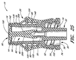
図24及び図25は、完全に組み立てられた医療用ソフトグリップ・コネクタ10の実施形態の断面図である。図示されている実施形態では、スリーブ20は、上方ハウジング40とリング60とルアー・スカート52の大部分とを含めて、ハウジング12を完全に囲んでいる。しかしながら、別の実施形態では、スリーブ20がハウジング12の一部を被覆することも考えられる。例えば、ある実施形態では、スリーブは、ハウジング12の上流端部16から下方へ、上方ハウジング40の高さのおよそ半分〜上方ハウジング40全体まで被覆していてもよい。別の実施形態では、スリーブ20は、ハウジング12の上流端部16から下方へ、上方ハウジング40の高さのおよそ4分の1〜半分まで被覆していてもよい。同様に、図7〜図11に示されているような、2つの部品から成るハウジングを備えた医療用コネクタ10の様々な実施形態では、スリーブ20は、第1ハウジング部分41の一部、第1ハウジング部分41のほぼ全部、第1ハウジング部分の全部と第2ハウジング部分51の一部、又は、第1ハウジング部分の全部と第2ハウジング部分51のほぼ全部を囲んでいてもよい。また、スリーブ20は、ハウジング12の溝46を通って延びる側方延長部84も囲み得る。
24 and 25 are cross-sectional views of an embodiment of the fully assembled medical
図24及び図25は、密閉状態(即ち、コネクタを流体が流れないようにされた状態)に組み立てられたコネクタの一例を示している。バルブ部材14は、その第1及び第2側方延長部84がハウジング12の第1及び第2の溝46から突出するように、ハウジング12の上方キャビティ42内に配置される。バルブ部材14のリード管腔102は、内側カニューレ50がこのリード管腔102内部へ少なくとも途中まで延びるように配置され、これにより、コネクタが(図15及び図16に示されているような)開放状態にあるとき、バルブ部材14とルアー・カニューレ32との間で流体が連通しやすくなる。フランジ90は、ハウジング12の上流端部16における軸方向の開口部をカバーしている。
24 and 25 show an example of the connector assembled in a sealed state (that is, a state in which fluid is prevented from flowing through the connector). The
ハウジング12の外面上にスリーブ20があることによって、医療提供者はコネクタ10をより楽に且つ効果的に掴むことができる。スリーブ20の可撓性材料は、より柔らかい表面を指に提供する。スリーブ20の可撓性材料と医療提供者が一般的にはめるゴム手袋との間には摩擦の大きい界面があるのが好ましく、このような界面があると、接続及び流体投与処理の際に、コネクタ10をカテーテル又はその他の医療器具に螺合させて所望の位置及び向きに維持するのに必要な、指で摘まむ力がより少なくて済む。
The presence of the
ハウジング12の外部を囲むスリーブ20は、柔らかくて掴みやすい外面を提供するのに加えて、コネクタの取り扱い中及び使用中に、側方延長部が摘ままれないように又はその他の方法で不都合に操作されないようにする。一実施形態では、バルブ部材14及びハウジング12は、ハウジング12の上流端部16と溝46の頂縁部140との間の距離が、フランジ90とバルブ部材14の側方延長部84のショルダー92との間の距離よりもわずかに大きくなるように構成されている。このような構造により、張力若しくは前負荷は、バルブ部材14のフランジ90と側方延長部84との間にかかる。
In addition to providing a soft, easy-to-grip outer surface, the
ショルダー92がハウジングの頂縁部140に荷重をかけ、密閉フランジ90がハウジングの上流端部16及び/又はこの上流端部における軸方向の開口部のショルダー142に荷重をかけると、前負荷が生じる。ある実施形態では、ハウジングの上流端部16の縁部がフランジ90の下側に荷重をかけると、この前負荷によって、フランジ90は、わずかに椀形若しくは凹形となる。この椀形フランジ90は、スリット穴100をよりしっかりときつく閉鎖しやすいため、バルブ部材14は、流体の流れをより阻止することができるようになる。また、この前負荷によって、バルブ部材14がその長手方向軸に沿って曲がらず、スリット94の両側部がその全長に沿って互いに近接した状態に維持される。従って、このような前負荷により、フランジ90の下にあるスリット94は比較的細くなり、これによって、スリット94の密閉性能が高まる。ある実施形態では、ショルダー92と内側カニューレ50の開口部148との間の距離は、バルブ部材14のリード管腔102がハウジング12の内側カニューレ50と係合して密着するようなサイズとされている。
When the
次に、図26及び図27を参照すると、コネクタ10を使用する際、例えば注射器のような医療機器202のカニューレ200をコネクタ10のバルブ部材14に挿入することができ、これにより、バルブ部材14が開放され、医療機器202とコネクタ10のルアー・カニューレ32との間において流体の流れ204が生じる。
26 and 27, when the
カニューレ200が挿入される前、コネクタ10は密閉状態である(例えば、図24及び図25参照)。この状態では、スリット94は、バルブ部材14を通るほぼ閉鎖された又は非常に制限された流路を画定している。図16に示されているように、カニューレ200がスリット94を通って挿入されると、バルブ部材14は、コネクタ10内に流体経路を開放する一方、医療機器202のカニューレ200に対して内側向きの力を及ぼし、これによって、好ましくは、カニューレ200の周囲に密着し、コネクタ10の上流端部を通って流体が漏れるのを防ぐ。また、カニューレ200をバルブ部材14に挿入することにより、バルブ部材14は下流方向に伸びて内側カニューレ50を被覆する。
Before the
医療機器202からカニューレ200を通ってバルブ部材14の内部空間へ流体が注入されると、スリット壁206間の空間は更に大きくなり、スリット壁206は更に拡張して下流方向に更に長くなる。従って、このバルブ部材14は、選択的に、流体204が、コネクタ10の上流端部に取り付けられる医療機器202と、下方にあるルアー・コネクタ30に取り付けられる医療器具(図示せず)との間を流れるようにする。
When fluid is injected from the
図26及び図27に示されているように、コネクタ10は、開放状態である場合、流体の流れ204が好ましくはほぼ妨げられず直線状であるようにする。これにより、通常、コネクタは流速をより速くすることができる。ある実施形態では、コネクタ10を通る流体の流速は、600cm3/分を超えることもある。更に、このような妨げられず直線状である流体の流れ204は、その元々の特性を阻害することが少ない。例えば、流体の流れ204が血液である場合、流体経路が回り道になっているため流体が乱流となって硬い且つ/又は角度のある内面にぶつかるようなコネクタに比べて、図示されているようなコネクタ10内では、様々な血球及びその他の成分が壊れる可能性が低い。
As shown in FIGS. 26 and 27, when the
流体の流れ204が少なくなる、且つ/又は、医療機器202のカニューレ200がバルブ部材14から引き抜かれると、スリット壁206は、収縮して元の形状に戻り、それらの間の通路幅を(例えば、図24及び図25に示されているような)細く制限されたものに画定し直す。このようにスリット壁206が収縮することにより、スリット94内の容積は所定の最小限度まで減少する。また、このようなスリット壁206の収縮動作は、これらの壁206の間の領域に残った流体も押し出す。注射器のカニューレ200が引き抜かれているとき、この押し出された流体がバルブ部材14の上流端部を通ってスリット94から流出することができないのは、この空間が注射器のカニューレ200によって占有されているからである。スリット94の弾性で細いネック97は、カニューレ200の周囲に密着することによって、カニューレ200の外面と可撓性部材80の内面との間における流体の大きな流れをいずれも遮断するのが好ましい。従って、この押し出された流体は、代わりに、スリット94から下方へ余儀なく流れ、内側カニューレ50及びその下方にあるカニューレ32を通って、最終的にハウジング12から流出する。これにより、有益なことに、コネクタ10の上流端部から医療機器202を引き抜くと、コネクタ10から患者へ向かう正流が自動的に生じると共に、患者からコネクタ10へ向かう流体の逆流が回避されるか或いは最小限に抑えられる。
When the
上記説明は注射器に関するものであるが、このコネクタ10の片方の端部には、流体の移送又はその他あらゆる所望の目的で、あらゆるタイプの適切な医療機器(例えば、点滴用の袋、別のコネクタ、チューブ)を接合することが考えられる。また、このソフトグリップ・コネクタには、補助コネクタを結合してもよく、これら両方のコネクタは、一端が患者内に位置付けられたカテーテルと流体連通するように配置され得る。このような構造は、特有の補助コネクタを使用することが必要な状況において、いくつかの利点をもたらすことができる。例えば、補助コネクタに結合された流体ラインを交換する又は再構成する必要がある場合、このようなラインは、カテーテルに逆流を起こさずにカテーテルとの流体連通から外され、同様のコネクタ又はその他あらゆる医療器具と交換される。ある実施形態では、このような補助コネクタは、ICUメディカル社によって販売されているCLAVE(登録商標)コネクタであってもよい。しかしながら、患者に流体を導入する又は患者から血液を採り出すのに、あらゆるコネクタ又はその他の医療器具若しくは医療機器(例えば、穿孔可能コネクタ、無針コネクタ、医療用チューブ、注射器、又はその他あらゆる医療器具若しくは医療機器が挙げられるが、これらに限定されない)を、ソフトグリップ・コネクタ10と流体連通するように配置してもよい。
While the above description relates to a syringe, one end of the
本明細書中では特定の実施形態及び実施例について説明してきたが、当業者には、本開示で図示及び説明した方法及び装置の多数の態様を違った形に組み合わせたり変更したりして、更に別の実施形態を形成してもよい、ということは理解されるであろう。例えば、ハウジングの様々な実施形態を可撓性部材の様々な実施形態に交換可能に適用して、医療用ソフトグリップ・コネクタの多様な実施形態を形成してもよい。更に、本明細書中で説明した方法は、ここで説明した工程を行うのに適した装置であれば、どのような装置を用いて実施してもよい、ということは認められるであろう。上記方法及び装置の別の実施形態及び/又は使用法、並びにその明らかな変更物及び等価物は、本開示の範囲内にあることが意図される。従って、本発明の範囲は、上記特定の実施形態によって制限されるべきではなく、添付の特許請求の範囲を公正に読むことによってのみ決められるべきである、ということが意図される。 Although specific embodiments and examples have been described herein, those skilled in the art will recognize that various aspects of the methods and apparatus illustrated and described in this disclosure may be combined or modified in different ways, It will be appreciated that still other embodiments may be formed. For example, various embodiments of the housing may be interchangeably applied to various embodiments of the flexible member to form various embodiments of the medical soft grip connector. Furthermore, it will be appreciated that the methods described herein may be implemented using any apparatus suitable for performing the steps described herein. Other embodiments and / or uses of the above methods and apparatus, and obvious variations and equivalents thereof, are intended to be within the scope of this disclosure. Accordingly, it is intended that the scope of the invention should not be limited by the specific embodiments described above, but only determined by a fair reading of the appended claims.
Claims (42)
把持部分と一体形成されたバルブ部分を有する、可撓性部材であって、前記バルブ部分が、前記ハウジングの一部内に配置されていると共に、前記ハウジングの管腔を通る流体の流れを制御するように構成されており、前記把持部分が、前記ハウジングの外面の少なくとも一部を実質的に囲んでいる、可撓性部材と、
を備える、医療用ソフトグリップ・コネクタ。 A housing having an upstream end, a downstream end, and a lumen extending through the central portion;
A flexible member having a valve portion integrally formed with a gripping portion, wherein the valve portion is disposed within a portion of the housing and controls fluid flow through the lumen of the housing. A flexible member, wherein the gripping portion substantially surrounds at least a portion of the outer surface of the housing;
A soft grip connector for medical use.
前記円筒体の第1端部と第2端部との間を密閉する、バルブ部分と、
前記バルブ部分と一体形成され、前記円筒体の外面の大部分を囲む、スリーブ部分と、
を備える、医療用流体コネクタ。 A cylindrical body having an outer wall with a plurality of radially extending flanges and a lumen extending therethrough;
A valve portion for sealing between the first end and the second end of the cylindrical body;
A sleeve portion integrally formed with the valve portion and enclosing most of the outer surface of the cylindrical body;
A medical fluid connector comprising:
前記プレフォーム型から前記第1プレフォームを取り外す工程と、
第2プレフォームを成型する工程と、
前記第1プレフォーム及び前記第2プレフォームを最終型に挿入する工程と、
未硬化材料を前記最終型に注入して、前記第1プレフォーム及び前記第2プレフォームを、バルブ部分と該バルブ部分から延出するスリーブ部分とを有する最終構造にオーバーモールドする工程と、
を含む、医療機器形成方法。 Molding a first preform from a substantially flexible material by injecting an uncured material into the preform mold;
Removing the first preform from the preform mold;
Forming a second preform;
Inserting the first preform and the second preform into a final mold;
Injecting uncured material into the final mold and overmolding the first preform and the second preform into a final structure having a valve portion and a sleeve portion extending from the valve portion;
A method of forming a medical device.
比較的剛性のハウジングを形成する工程と、
前記スリーブが前記ハウジングから延出するように、前記バルブ部材の一部を前記ハウジングのキャビティに挿入する工程と、
前記ハウジングの外面を囲むように前記スリーブを裏返す工程と、
を含む、医療用流体コネクタ製造方法。 Integrally forming a valve member and a sleeve extending from the valve member from a substantially flexible material;
Forming a relatively rigid housing;
Inserting a portion of the valve member into a cavity of the housing such that the sleeve extends from the housing;
Turning the sleeve over so as to surround the outer surface of the housing;
A method for manufacturing a medical fluid connector.
Applications Claiming Priority (3)
| Application Number | Priority Date | Filing Date | Title |
|---|---|---|---|
| US62564404P | 2004-11-05 | 2004-11-05 | |
| US65425005P | 2005-02-18 | 2005-02-18 | |
| PCT/US2005/039791 WO2006052655A2 (en) | 2004-11-05 | 2005-11-04 | Soft-grip medical connector |
Publications (2)
| Publication Number | Publication Date |
|---|---|
| JP2008518719A true JP2008518719A (en) | 2008-06-05 |
| JP2008518719A5 JP2008518719A5 (en) | 2009-02-05 |
Family
ID=36155599
Family Applications (1)
| Application Number | Title | Priority Date | Filing Date |
|---|---|---|---|
| JP2007540025A Pending JP2008518719A (en) | 2004-11-05 | 2005-11-04 | Medical soft grip connector |
Country Status (13)
| Country | Link |
|---|---|
| US (18) | US20060161115A1 (en) |
| EP (2) | EP1990070B1 (en) |
| JP (1) | JP2008518719A (en) |
| CN (1) | CN101068592B (en) |
| AT (1) | ATE542564T1 (en) |
| AU (1) | AU2005304987B2 (en) |
| BR (1) | BRPI0517062B8 (en) |
| CA (1) | CA2586115C (en) |
| DK (1) | DK1990070T3 (en) |
| ES (1) | ES2380911T3 (en) |
| HK (2) | HK1115074A1 (en) |
| MX (1) | MX2007005324A (en) |
| WO (1) | WO2006052655A2 (en) |
Cited By (15)
| Publication number | Priority date | Publication date | Assignee | Title |
|---|---|---|---|---|
| JP2013538073A (en) * | 2010-07-19 | 2013-10-10 | ベクトン・ディキンソン・アンド・カンパニー | Luer connector |
| JP2015517377A (en) * | 2012-05-21 | 2015-06-22 | カルメル ファルマ アクチボラゲット | Placement in medical connector device |
| JP2015119837A (en) * | 2013-12-24 | 2015-07-02 | 株式会社ジェイ・エム・エス | Male connector |
| JP2015211881A (en) * | 2010-05-27 | 2015-11-26 | ジェイ アンド ジェイ ソリューションズ,インコーポレイテッド | Closed fluid transfer system |
| JP2015533621A (en) * | 2012-11-12 | 2015-11-26 | アイシーユー・メディカル・インコーポレーテッド | Medical connector |
| JP2017526511A (en) * | 2014-09-08 | 2017-09-14 | ネオメッド, インクNeomed, Inc. | Vent connector for chemical liquid conduit |
| JP2017528269A (en) * | 2014-09-25 | 2017-09-28 | コヴィディエン リミテッド パートナーシップ | Enteral feeding connector |
| JP2018122165A (en) * | 2018-05-16 | 2018-08-09 | カルメル ファルマ アクチボラゲット | Deployment in medical connector device |
| JP2018164807A (en) * | 2018-08-03 | 2018-10-25 | 株式会社ジェイ・エム・エス | Male connector |
| JP2020058945A (en) * | 2020-01-27 | 2020-04-16 | 株式会社ジェイ・エム・エス | Male connector |
| JP2020534056A (en) * | 2017-09-15 | 2020-11-26 | ネオメッド, インクNeomed, Inc. | Hub component for vented connectors |
| JP2021037347A (en) * | 2020-11-26 | 2021-03-11 | 株式会社ジェイ・エム・エス | Male connector |
| JP2021527467A (en) * | 2018-06-21 | 2021-10-14 | ベクトン・ディキンソン・アンド・カンパニーBecton, Dickinson And Company | Enteral syringe with vented collar |
| US11357964B2 (en) | 2014-09-08 | 2022-06-14 | Avent, Inc. | Vented connector for medical fluid vessels and tapered plug |
| KR102592609B1 (en) * | 2023-06-30 | 2023-10-23 | 엔지오텍 주식회사 | Lure connector structure with air drain hole |
Families Citing this family (161)
| Publication number | Priority date | Publication date | Assignee | Title |
|---|---|---|---|---|
| US6695817B1 (en) | 2000-07-11 | 2004-02-24 | Icu Medical, Inc. | Medical valve with positive flow characteristics |
| US7435236B2 (en) | 2003-06-27 | 2008-10-14 | Navilyst Medical, Inc. | Pressure actuated valve with improved biasing member |
| US8636721B2 (en) | 2003-11-20 | 2014-01-28 | Henry M. Jackson Foundation For The Advancement Of Military Medicine, Inc. | Portable hand pump for evacuation of fluids |
| HK1077154A2 (en) * | 2003-12-30 | 2006-02-03 | Vasogen Ireland Ltd | Valve assembly |
| US8337475B2 (en) | 2004-10-12 | 2012-12-25 | C. R. Bard, Inc. | Corporeal drainage system |
| WO2006052655A2 (en) | 2004-11-05 | 2006-05-18 | Icu Medical, Inc. | Soft-grip medical connector |
| US7615035B2 (en) * | 2005-03-24 | 2009-11-10 | B. Braun Medical Inc. | Needleless access port valves |
| WO2007006055A2 (en) | 2005-07-06 | 2007-01-11 | Vascular Pathways Inc. | Intravenous catheter insertion device and method of use |
| US7998134B2 (en) | 2007-05-16 | 2011-08-16 | Icu Medical, Inc. | Medical connector |
| US20070088293A1 (en) | 2005-07-06 | 2007-04-19 | Fangrow Thomas F Jr | Medical connector with closeable male luer |
| WO2007038643A1 (en) | 2005-09-26 | 2007-04-05 | C.R. Bard, Inc. | Catheter connection systems |
| US7625392B2 (en) * | 2006-02-03 | 2009-12-01 | James Coleman | Wound closure devices and methods |
| US20080021415A1 (en) * | 2006-04-07 | 2008-01-24 | Anthony Durkin | Device suitable for connection to a substantially tubular element |
| CA2649438A1 (en) * | 2006-04-11 | 2007-10-25 | Nypro Inc. | Medical valve with moving member and method |
| US20080033347A1 (en) * | 2006-08-03 | 2008-02-07 | Becton, Dickinson And Company | Detachable needle syringe having reduced dead space |
| AU2007286053B2 (en) | 2006-08-11 | 2012-11-15 | Nypro Inc. | Medical valve with expandable member |
| JP4994775B2 (en) | 2006-10-12 | 2012-08-08 | 日本コヴィディエン株式会社 | Needle point protector |
| US7981090B2 (en) | 2006-10-18 | 2011-07-19 | Baxter International Inc. | Luer activated device |
| US20080172004A1 (en) * | 2006-10-18 | 2008-07-17 | Michael Plishka | Luer activated device with stretchable valve element |
| US8221363B2 (en) | 2006-10-18 | 2012-07-17 | Baxter Healthcare S.A. | Luer activated device with valve element under tension |
| US7753338B2 (en) | 2006-10-23 | 2010-07-13 | Baxter International Inc. | Luer activated device with minimal fluid displacement |
| ATE506985T1 (en) | 2006-10-25 | 2011-05-15 | Icu Medical Inc | MEDICAL CONNECTOR |
| US20080128646A1 (en) * | 2006-12-05 | 2008-06-05 | Humitek, Inc. | Splines and caps for fluid ports |
| US8443808B2 (en) | 2007-03-19 | 2013-05-21 | Hologic, Inc. | Methods and apparatus for occlusion of body lumens |
| EP2150304B1 (en) | 2007-05-07 | 2010-12-01 | Vascular Pathways Inc. | Intravenous catheter insertion and blood sample devices and method of use |
| US8597237B2 (en) * | 2007-05-18 | 2013-12-03 | Carefusion 303, Inc. | Universal needlefree bag access device |
| WO2008145123A1 (en) * | 2007-06-01 | 2008-12-04 | Unomedical A/S | Urine measurement vessel and hose connection |
| US20090043270A1 (en) * | 2007-08-10 | 2009-02-12 | C.R. Bard, Inc. | Effusion drainage kits and methods for packaging the same |
| US20090099552A1 (en) * | 2007-10-12 | 2009-04-16 | Maureen Levy | Drug delivery route-based connector system and method |
| US9301761B2 (en) | 2007-10-22 | 2016-04-05 | James E. Coleman | Anastomosis devices and methods |
| CN101965372A (en) * | 2008-01-04 | 2011-02-02 | Cr巴德公司 | Synthetic polyisoprene foley catheter |
| US8092416B2 (en) | 2008-03-28 | 2012-01-10 | Vitalmex Internacional S.A. De C.V. | Device and method for connecting a blood pump without trapping air bubbles |
| US8414554B2 (en) | 2008-05-14 | 2013-04-09 | J & J Solutions, Inc. | Systems and methods for safe medicament transport |
| US8037895B2 (en) * | 2008-05-20 | 2011-10-18 | Vivant Medical, Inc. | Coolant line clip assemblies for use with fluid delivery systems |
| US8257321B2 (en) | 2008-05-21 | 2012-09-04 | Navilyst Medical, Inc. | Pressure activated valve for high flow rate and pressure venous access applications |
| CA2729673A1 (en) * | 2008-06-30 | 2010-01-07 | C.R. Bard, Inc. | Polyurethane/polyisoprene blend catheter |
| US20100030164A1 (en) * | 2008-08-04 | 2010-02-04 | Np Medical Inc. | Medical Valve with Raised Seal |
| US20100036330A1 (en) * | 2008-08-11 | 2010-02-11 | Baxter International Inc. | Needleless connector with displacement correction |
| US9078992B2 (en) | 2008-10-27 | 2015-07-14 | Pursuit Vascular, Inc. | Medical device for applying antimicrobial to proximal end of catheter |
| US8197498B2 (en) | 2008-11-06 | 2012-06-12 | Trinitas Ventures Ltd. | Gastric bypass devices and procedures |
| US8679090B2 (en) | 2008-12-19 | 2014-03-25 | Icu Medical, Inc. | Medical connector with closeable luer connector |
| US9168366B2 (en) | 2008-12-19 | 2015-10-27 | Icu Medical, Inc. | Medical connector with closeable luer connector |
| US8523828B2 (en) | 2008-12-30 | 2013-09-03 | Covidien Lp | Clamping assembly for use with a catheter |
| US8419694B2 (en) | 2008-12-30 | 2013-04-16 | Covidien Lp | Extension tube clamps for use with a catheter |
| US8454579B2 (en) | 2009-03-25 | 2013-06-04 | Icu Medical, Inc. | Medical connector with automatic valves and volume regulator |
| US8221388B2 (en) * | 2009-04-22 | 2012-07-17 | Tyco Healthcare Group Lp | Biased clamping assemblies |
| MX2012000065A (en) | 2009-06-22 | 2012-05-22 | Np Medical Inc | Medical valve with improved back-pressure sealing. |
| US8007468B2 (en) | 2009-07-13 | 2011-08-30 | Navilyst Medical, Inc. | Method to secure an elastic component in a valve |
| US8731638B2 (en) * | 2009-07-20 | 2014-05-20 | Optiscan Biomedical Corporation | Adjustable connector and dead space reduction |
| US8715247B2 (en) | 2009-07-30 | 2014-05-06 | Carefusion 303, Inc. | Collapsible valve |
| US8454563B2 (en) * | 2009-10-09 | 2013-06-04 | Rogelio A. Insignares | Trocar and cannula assembly having improved conical valve, and methods related thereto |
| CN101794937B (en) * | 2009-12-29 | 2013-01-09 | 鸿富锦精密工业(深圳)有限公司 | Electronic equipment with bracket |
| USD644731S1 (en) | 2010-03-23 | 2011-09-06 | Icu Medical, Inc. | Medical connector |
| CN102834140B (en) * | 2010-03-23 | 2015-11-25 | N.V.努特里西阿公司 | For the three-dimensional cut-out tap of enteral tube feed application |
| KR101540929B1 (en) | 2010-04-05 | 2015-08-03 | 다니엘 파이 | Aseptic connector with deflectable ring of concern and method |
| WO2011140073A2 (en) | 2010-05-03 | 2011-11-10 | Optiscan Biomedical Corporation | Adjustable connector, improved fluid flow and reduced clotting risk |
| EP2550058B1 (en) | 2010-05-06 | 2014-03-26 | ICU Medical, Inc. | Medical connector with closeable luer connector |
| US9950139B2 (en) | 2010-05-14 | 2018-04-24 | C. R. Bard, Inc. | Catheter placement device including guidewire and catheter control elements |
| US9872971B2 (en) | 2010-05-14 | 2018-01-23 | C. R. Bard, Inc. | Guidewire extension system for a catheter placement device |
| US10384039B2 (en) | 2010-05-14 | 2019-08-20 | C. R. Bard, Inc. | Catheter insertion device including top-mounted advancement components |
| US8932258B2 (en) | 2010-05-14 | 2015-01-13 | C. R. Bard, Inc. | Catheter placement device and method |
| US11925779B2 (en) | 2010-05-14 | 2024-03-12 | C. R. Bard, Inc. | Catheter insertion device including top-mounted advancement components |
| US8758306B2 (en) | 2010-05-17 | 2014-06-24 | Icu Medical, Inc. | Medical connectors and methods of use |
| US9138572B2 (en) | 2010-06-24 | 2015-09-22 | Np Medical Inc. | Medical valve with fluid volume alteration |
| US8459508B2 (en) | 2010-07-30 | 2013-06-11 | S.C. Johnson & Son, Inc. | Shroud for a dispenser |
| US8474663B2 (en) * | 2010-07-30 | 2013-07-02 | S.C. Johnson & Son, Inc. | Adapter for a dispenser |
| US9687644B2 (en) | 2010-09-02 | 2017-06-27 | Hollister Incorporated | Soft, flexible connector |
| US8690833B2 (en) | 2011-01-31 | 2014-04-08 | Vascular Pathways, Inc. | Intravenous catheter and insertion device with reduced blood spatter |
| US9163764B2 (en) * | 2011-02-15 | 2015-10-20 | Cws-Boco Supply Ag | Valve for liquid vessels |
| EP3563898B1 (en) | 2011-02-25 | 2020-11-11 | C.R. Bard, Inc. | Medical component insertion device including a retractable needle |
| ES2662356T3 (en) | 2011-04-27 | 2018-04-06 | Kpr U.S., Llc | Safety IV catheter assemblies |
| USD903101S1 (en) | 2011-05-13 | 2020-11-24 | C. R. Bard, Inc. | Catheter |
| US10016587B2 (en) | 2011-05-20 | 2018-07-10 | Excelsior Medical Corporation | Caps for needleless connectors |
| ES2797649T3 (en) | 2011-07-12 | 2020-12-03 | Icu Medical Inc | Device for the delivery of antimicrobial agent in a transdermal catheter |
| SE538414C2 (en) | 2011-08-10 | 2016-06-21 | Fisher & Paykel Healthcare Ltd | Conductor connector for a breathing device for a patient |
| US20130069365A1 (en) * | 2011-09-06 | 2013-03-21 | James L. Pokorney | Tapered Bore Connector |
| WO2013036854A1 (en) | 2011-09-09 | 2013-03-14 | Icu Medical, Inc. | Medical connectors with fluid-resistant mating interfaces |
| US8715250B2 (en) | 2011-09-26 | 2014-05-06 | Covidien Lp | Safety catheter and needle assembly |
| WO2013048975A1 (en) | 2011-09-26 | 2013-04-04 | Covidien Lp | Safety catheter |
| US8834422B2 (en) | 2011-10-14 | 2014-09-16 | Covidien Lp | Vascular access assembly and safety device |
| EP2790771B1 (en) | 2011-12-13 | 2018-10-03 | Oridion Medical 1987 Ltd. | Luer connectors |
| US9247930B2 (en) | 2011-12-21 | 2016-02-02 | James E. Coleman | Devices and methods for occluding or promoting fluid flow |
| EP2838602A4 (en) | 2012-04-17 | 2016-04-20 | Py Inst Llc Dr | Self closing connector |
| BR112014027280A2 (en) | 2012-05-01 | 2017-06-27 | Py Dr Inst Llc | device for connection or filling and method |
| US10351271B2 (en) | 2012-05-01 | 2019-07-16 | Dr. Py Institute Llc | Device for connecting or filling and method |
| US9895524B2 (en) | 2012-07-13 | 2018-02-20 | Angiodynamics, Inc. | Fluid bypass device for valved catheters |
| US10441775B2 (en) * | 2013-05-01 | 2019-10-15 | Bayer Healthcare Llc | Fluid path set bolus control device |
| US9320867B2 (en) * | 2013-05-22 | 2016-04-26 | Pall Corporation | Connection system |
| ITTO20130433A1 (en) * | 2013-05-29 | 2014-11-30 | Borla Ind | CONNECTOR FOR MEDICAL LINES |
| US9415199B2 (en) * | 2013-06-14 | 2016-08-16 | Skill Partner Limited | Leak proof needleless medical connector |
| AU2014295975B2 (en) | 2013-08-02 | 2018-08-02 | J&J SOLUTIONS, INC. d.b.a CORVIDA MEDICAL | Compounding systems and methods for safe medicament transport |
| EP3035997B1 (en) * | 2013-08-21 | 2018-04-11 | Cedic S.r.l. | Needlefree valve device |
| EP2862587A1 (en) | 2013-10-15 | 2015-04-22 | Becton Dickinson France | Tip cap assembly for closing an injection system |
| USD746446S1 (en) * | 2013-11-25 | 2015-12-29 | Medline Industries, Inc. | Connector |
| CA2932124C (en) | 2013-12-11 | 2023-05-09 | Icu Medical, Inc. | Check valve |
| US9981118B2 (en) * | 2014-01-14 | 2018-05-29 | King Faisal Specialist Hospital And Research Center | Implantable coupling assembly for a catheter tube and a valve device |
| DE102014101484A1 (en) * | 2014-02-06 | 2015-08-06 | Marco Systemanalyse Und Entwicklung Gmbh | connection system |
| US9752714B2 (en) * | 2014-03-28 | 2017-09-05 | Eldon James Corp. | Releasable valved coupler |
| CA2946566C (en) | 2014-04-21 | 2021-03-02 | Becton Dickinson and Company Limited | Fluid transfer device and packaging therefor |
| JP6356828B2 (en) * | 2014-04-21 | 2018-07-11 | ベクトン ディキンソン アンド カンパニー リミテッド | Fluid transfer device and packaging therefor |
| ES2755352T3 (en) | 2014-05-02 | 2020-04-22 | Excelsior Medical Corp | Strip pack for antiseptic cap |
| WO2016037127A1 (en) | 2014-09-05 | 2016-03-10 | C.R. Bard, Inc. | Catheter insertion device including retractable needle |
| US11376409B2 (en) | 2014-09-08 | 2022-07-05 | Avent, Inc. | Hub component for vented connector |
| USD793551S1 (en) | 2014-12-03 | 2017-08-01 | Icu Medical, Inc. | Fluid manifold |
| USD786427S1 (en) | 2014-12-03 | 2017-05-09 | Icu Medical, Inc. | Fluid manifold |
| US10624817B2 (en) | 2015-03-24 | 2020-04-21 | Neomed, Inc. | Oral administration coupler for back-of-mouth delivery |
| AU2016242101B2 (en) | 2015-03-31 | 2020-12-24 | Fisher & Paykel Healthcare Limited | Apparatus for use in a respiratory support system |
| USD903100S1 (en) | 2015-05-01 | 2020-11-24 | C. R. Bard, Inc. | Catheter placement device |
| CA2982456A1 (en) | 2015-05-08 | 2016-11-17 | Icu Medical, Inc. | Medical connectors configured to receive emitters of therapeutic agents |
| KR102553637B1 (en) | 2015-05-15 | 2023-07-07 | 씨. 알. 바드, 인크. | Catheter Placement Device Including Extendable Needle Safety Component |
| CA2989055C (en) * | 2015-06-26 | 2023-10-17 | Coloplast A/S | A urinary catheter assembly |
| MX2018003089A (en) | 2015-09-17 | 2018-05-11 | J&J Solutions Inc D/B/A Corvida Medical | Medicament vial assembly. |
| JP2018530396A (en) | 2015-10-13 | 2018-10-18 | ジェイ アンド ジェイ ソリューションズ,インコーポレイテッド | Automatic compounding equipment for closed fluid transfer systems. |
| DE102015118813A1 (en) * | 2015-11-03 | 2017-05-04 | Hans-Jürgen Hopf | Connection system with union nut |
| EP3405231A4 (en) | 2016-01-19 | 2019-10-16 | Daniel Py | Single use connectors |
| US20170224974A1 (en) * | 2016-02-09 | 2017-08-10 | Amt Pte Ltd | Medical device adapter with luer lock output fitting |
| US10589038B2 (en) * | 2016-04-27 | 2020-03-17 | Medtronic Minimed, Inc. | Set connector systems for venting a fluid reservoir |
| USD809656S1 (en) * | 2016-06-10 | 2018-02-06 | Fisher & Paykel Healthcare Limited | Connector for a breathing circuit |
| AU2017299466B2 (en) | 2016-07-18 | 2022-07-14 | Merit Medical Systems, Inc. | Inflatable radial artery compression device |
| US10610678B2 (en) | 2016-08-11 | 2020-04-07 | Angiodynamics, Inc. | Bi-directional, pressure-actuated medical valve with improved fluid flow control and method of using such |
| CN116173370A (en) | 2016-09-12 | 2023-05-30 | C·R·巴德股份有限公司 | Blood flash indicator for catheterization apparatus |
| WO2018059637A1 (en) | 2016-09-27 | 2018-04-05 | Coloplast A/S | A hydrated catheter with sleeve |
| AU2017341782B2 (en) | 2016-10-14 | 2023-03-16 | Icu Medical, Inc. | Sanitizing caps for medical connectors |
| US10835730B2 (en) | 2016-12-23 | 2020-11-17 | Np Medical Inc. | Sampling port for hemodynamic monitoring systems |
| US10368789B2 (en) * | 2016-12-23 | 2019-08-06 | Np Medical Inc. | Medical port with constraining biasing element |
| US11141306B2 (en) * | 2017-02-16 | 2021-10-12 | Harry Binnendyk | Urinary catheter connector |
| BR112019018016B1 (en) | 2017-03-01 | 2023-10-24 | C.R. Bard, Inc. | CATHETER INSERTION TOOL |
| US10857343B2 (en) * | 2017-04-06 | 2020-12-08 | Becton, Dickinson And Company | Medical devices with visual and tactile indicators |
| WO2018204206A2 (en) | 2017-05-01 | 2018-11-08 | Icu Medical, Inc. | Medical fluid connectors and methods for providing additives in medical fluid lines |
| EP4233989A3 (en) | 2017-06-07 | 2023-10-11 | Shifamed Holdings, LLC | Intravascular fluid movement devices, systems, and methods of use |
| JP7319266B2 (en) | 2017-11-13 | 2023-08-01 | シファメド・ホールディングス・エルエルシー | Intravascular fluid transfer devices, systems and methods of use |
| CN112004563A (en) | 2018-02-01 | 2020-11-27 | 施菲姆德控股有限责任公司 | Intravascular blood pump and methods of use and manufacture |
| WO2019168821A1 (en) * | 2018-02-28 | 2019-09-06 | Np Medical Inc. | Sampling port for hemodynamic monitoring systems |
| WO2019173641A1 (en) | 2018-03-07 | 2019-09-12 | Bard Access Systems, Inc. | Guidewire advancement and blood flashback systems for a medical device insertion system |
| EP3806927B1 (en) | 2018-06-13 | 2023-07-26 | Grove Group, LLC | Self-cleaning needleless connector |
| DK180417B1 (en) | 2018-07-20 | 2021-04-22 | Coloplast As | INTERMITTING URINCATHER FITTING |
| USD921884S1 (en) | 2018-07-27 | 2021-06-08 | Bard Access Systems, Inc. | Catheter insertion device |
| CN108785848B (en) * | 2018-09-07 | 2023-11-21 | 临沂市兴华医用器材有限公司 | Anesthesia catheter connector |
| US11400195B2 (en) | 2018-11-07 | 2022-08-02 | Icu Medical, Inc. | Peritoneal dialysis transfer set with antimicrobial properties |
| US11541220B2 (en) | 2018-11-07 | 2023-01-03 | Icu Medical, Inc. | Needleless connector with antimicrobial properties |
| US11517732B2 (en) | 2018-11-07 | 2022-12-06 | Icu Medical, Inc. | Syringe with antimicrobial properties |
| US11534595B2 (en) | 2018-11-07 | 2022-12-27 | Icu Medical, Inc. | Device for delivering an antimicrobial composition into an infusion device |
| US11541221B2 (en) | 2018-11-07 | 2023-01-03 | Icu Medical, Inc. | Tubing set with antimicrobial properties |
| CA3118905A1 (en) | 2018-11-21 | 2020-05-28 | Icu Medical, Inc. | Antimicrobial device comprising a cap with ring and insert |
| WO2020125908A1 (en) | 2018-12-20 | 2020-06-25 | Coloplast A/S | Urine collecting bag |
| JP2022540616A (en) | 2019-07-12 | 2022-09-16 | シファメド・ホールディングス・エルエルシー | Intravascular blood pump and methods of manufacture and use |
| WO2021016372A1 (en) | 2019-07-22 | 2021-01-28 | Shifamed Holdings, Llc | Intravascular blood pumps with struts and methods of use and manufacture |
| JP2022545447A (en) | 2019-08-19 | 2022-10-27 | ベクトン・ディキンソン・アンド・カンパニー | Midline catheter placement device |
| USD1006981S1 (en) | 2019-09-06 | 2023-12-05 | Fisher & Paykel Healthcare Limited | Breathing conduit |
| USD948027S1 (en) | 2019-09-10 | 2022-04-05 | Fisher & Paykel Healthcare Limited | Connector for a breathing conduit |
| EP4034192A4 (en) | 2019-09-25 | 2023-11-29 | Shifamed Holdings, LLC | Intravascular blood pump systems and methods of use and control thereof |
| USD940861S1 (en) | 2020-03-03 | 2022-01-11 | Fisher & Paykel Healthcare Limited | Connector for a respiratory system conduit |
| JP7298035B2 (en) * | 2020-06-16 | 2023-06-26 | リージェンツ オブ ザ ユニヴァーシティー オブ ミネソタ | rotary peritoneal dialysis interconnect |
| CA3194594A1 (en) * | 2020-10-12 | 2022-04-21 | Yiping Ma | Blood draw syringe with hemolysis protection |
| EP4255552A1 (en) | 2020-12-07 | 2023-10-11 | ICU Medical, Inc. | Peritoneal dialysis caps, systems and methods |
| USD974551S1 (en) | 2020-12-09 | 2023-01-03 | Fisher & Paykel Healthcare Limited | Connector assembly and connector |
| USD995758S1 (en) | 2021-06-11 | 2023-08-15 | Fisher & Paykel Healthcare Limited | Tube assembly and connector |
| CA3229515A1 (en) * | 2021-08-27 | 2023-03-02 | Abin AUSTIN | Single monolithic piece pivc-integrated hemolysis-reduction accessories for direct blood draw |
| US20230070065A1 (en) * | 2021-09-09 | 2023-03-09 | Carefusion 303, Inc. | Male luer connector |
| US11828388B2 (en) * | 2022-03-08 | 2023-11-28 | B. Braun Medical Inc. | Needle-free connector |
| WO2023192011A1 (en) * | 2022-04-01 | 2023-10-05 | Carefusion 303, Inc. | Overmolded hemolysis-reduction accessories for direct blood draw |
Family Cites Families (675)
| Publication number | Priority date | Publication date | Assignee | Title |
|---|---|---|---|---|
| US274447A (en) | 1883-03-20 | William-kentish | ||
| US1578517A (en) * | 1924-12-23 | 1926-03-30 | George N Hein | Valve piston and barrel construction for hypodermic syringes |
| US1923501A (en) | 1933-01-12 | 1933-08-22 | Agnes S Perry | Air valve and the like |
| US2210098A (en) * | 1936-04-11 | 1940-08-06 | Abbott Lab | Apparatus for venoclysis |
| US2289677A (en) * | 1940-09-24 | 1942-07-14 | Harold N Perelson | Rubber stopper |
| US2347988A (en) | 1943-10-20 | 1944-05-02 | Ormonde J Burke | Valve construction |
| US2577780A (en) | 1950-05-09 | 1951-12-11 | Compule Corp | Crowned cupped resilient plug for cylindrical passages |
| US2502097A (en) * | 1949-04-30 | 1950-03-28 | Ruby Lee Boyle | Parachute release mechanism |
| DE855319C (en) | 1951-06-05 | 1952-11-13 | Hermann Steiner | Jig for catheter |
| US2688979A (en) | 1951-08-31 | 1954-09-14 | John F Kendrick | Abrasion resistant check valve |
| US2756282A (en) | 1953-01-12 | 1956-07-24 | Sierra Electronic Corp | Directional amplifier system and apparatus |
| US2756740A (en) * | 1954-04-30 | 1956-07-31 | William V Deane | Drinking device for hospital patients |
| US2847995A (en) * | 1954-08-23 | 1958-08-19 | Becton Dickinson Co | Transfusion needle sheath |
| US2809665A (en) | 1955-02-01 | 1957-10-15 | Matthew R Crowe | Water hammer cushioning device |
| IT588491A (en) | 1956-06-15 | 1900-01-01 | ||
| US2999499A (en) | 1958-07-11 | 1961-09-12 | Cutter Lab | Flexible check valve |
| DE1432098A1 (en) | 1961-05-17 | 1969-10-09 | Bross Dipl Ing Helmut | Automatic closure with a safety device for containers with a deformable wall |
| US3135261A (en) * | 1961-09-21 | 1964-06-02 | Theodore H Chamberlin | Blood sampler |
| NL287509A (en) | 1962-01-09 | |||
| US3134380A (en) * | 1962-02-08 | 1964-05-26 | Thomas A Armao | Shielded hypodermic needle |
| US3191655A (en) | 1963-03-21 | 1965-06-29 | Us Rubber Co | Molded article, especially a tubeless tire valve stem assembly |
| US3352531A (en) | 1964-04-02 | 1967-11-14 | Scovill Manufacturing Co | Check valve |
| US3334860A (en) | 1964-07-13 | 1967-08-08 | Jr Cecil G Bolton | Fluid coupling |
| US3354881A (en) | 1964-11-03 | 1967-11-28 | Universal Oil Prod Co | Hypodermic needle protector |
| US3385301A (en) * | 1965-10-11 | 1968-05-28 | American Hospital Supply Corp | Balloon catheter having a deformable one-way inflation valve |
| US3502097A (en) * | 1966-06-08 | 1970-03-24 | Us Catheter & Instr Corp | Catheter-infuser connector |
| GB1192986A (en) | 1967-08-31 | 1970-05-28 | Eschmann Bros & Walsh Ltd | Intravenous Valve Assembly |
| US3534771A (en) | 1967-10-30 | 1970-10-20 | Eaton Yale & Towne | Valve assembly |
| US3630199A (en) | 1970-05-26 | 1971-12-28 | Louis P Gangarosa | Unitized injection system |
| US3648684A (en) * | 1970-08-04 | 1972-03-14 | Cleora W Barnwell | Device for the direct transfer of blood from a human to culture bottles |
| US3659602A (en) * | 1970-12-30 | 1972-05-02 | Nosco Plastics | Two component syringe |
| US3788519A (en) * | 1971-03-01 | 1974-01-29 | Eastman Kodak Co | Apparatus for piercing a container |
| US3717174A (en) | 1971-08-03 | 1973-02-20 | R Dewall | Perfusion safety valve |
| US3726282A (en) * | 1971-09-30 | 1973-04-10 | Kendall & Co | Inflation valve for catheter retention balloon |
| US3831629A (en) * | 1972-01-24 | 1974-08-27 | Halkey Roberts Corp | Check valve |
| US3896853A (en) | 1972-07-10 | 1975-07-29 | Pro Medical Eng Ab | Coupling means for use with blood sampling apparatus |
| US3830241A (en) | 1972-08-07 | 1974-08-20 | Kendall & Co | Vented adapter |
| US3852385A (en) | 1972-12-06 | 1974-12-03 | Med Pak Corp | Gas humidification apparatus |
| US3861388A (en) * | 1973-07-30 | 1975-01-21 | Robert Lee Vaughn | Apparatus for administering supplemental medication with parenteral solutions |
| US3986508A (en) | 1973-08-22 | 1976-10-19 | Abcor, Inc. | Sterilizable, medical connector for blood processing |
| US4022205A (en) * | 1973-11-05 | 1977-05-10 | Tenczar Francis J | Fluid connectors |
| US3976073A (en) | 1974-05-01 | 1976-08-24 | Baxter Laboratories, Inc. | Vial and syringe connector assembly |
| FR2269970A1 (en) | 1974-05-07 | 1975-12-05 | Crinospital Spa | |
| US3889675A (en) | 1974-06-25 | 1975-06-17 | Stewart Research | Suction-irrigator |
| US3976063A (en) | 1974-09-16 | 1976-08-24 | The Bendix Corporation | Escape breathing apparatus |
| US3974832A (en) | 1975-01-07 | 1976-08-17 | Vca Corporation | Interchangeable hypodermic needle assemblage |
| US4005710A (en) * | 1975-02-12 | 1977-02-01 | Abbott Laboratories | Parenteral apparatus with one-way valve |
| US3977403A (en) | 1975-02-24 | 1976-08-31 | The Kendall Company | Catheter adapter |
| US3965910A (en) * | 1975-04-28 | 1976-06-29 | Walpak Company | Urinary irrigation valve |
| US3993063A (en) | 1975-06-16 | 1976-11-23 | Union Carbide Corporation | Protective shielding assembly for use in loading a hypodermic syringe with radioactive material |
| US4076285A (en) * | 1975-08-01 | 1978-02-28 | Erika, Inc. | Laminar flow connector for conduits |
| US4186775A (en) | 1975-10-07 | 1980-02-05 | Tozen Sangyo Co., Ltd. | Water hammer shock absorber |
| US4019512A (en) * | 1975-12-04 | 1977-04-26 | Tenczar Francis J | Adhesively activated sterile connector |
| US4040420A (en) | 1976-04-22 | 1977-08-09 | General Dynamics | Packaging and dispensing kit |
| LU77252A1 (en) * | 1976-05-06 | 1977-08-22 | ||
| FR2354104A1 (en) | 1976-06-09 | 1978-01-06 | Charvin Guy | INTRAVENOUS CANNULA DEVICE |
| US4079738A (en) * | 1976-09-20 | 1978-03-21 | Sorenson Research Co., Inc. | Needle restraining apparatus |
| US4080965A (en) * | 1976-09-30 | 1978-03-28 | Baxter Travenol Laboratories, Inc. | In-line cannula valve assembly |
| US4128098A (en) | 1976-12-06 | 1978-12-05 | American Hospital Supply Corporation | Valved spike transfer device |
| US4121585A (en) | 1977-01-24 | 1978-10-24 | Becker Jr Karl E | Anti backflow injection device |
| SE415728B (en) * | 1977-03-07 | 1980-10-27 | Gambro Ab | COUPLING |
| AU3775578A (en) | 1977-07-08 | 1980-01-10 | Johnson & Johnson | Vented filter assembly |
| US4143853A (en) * | 1977-07-14 | 1979-03-13 | Metatech Corporation | Valve for use with a catheter or the like |
| GB2001146B (en) | 1977-07-14 | 1982-05-19 | Smiths Industries Ltd | Valve assemblies |
| US4161949A (en) * | 1977-10-27 | 1979-07-24 | Pennwalt Corporation | Aseptic connector |
| US4191183A (en) * | 1977-10-31 | 1980-03-04 | Barry Mendelson | Mixing chamber for use in plural medical liquid intravenous administration set |
| US4198983A (en) | 1978-04-28 | 1980-04-22 | Baxter Travenol Laboratories, Inc. | Catheter made of a thermoplastic material having improved softness and low friction |
| US4133441A (en) | 1978-03-23 | 1979-01-09 | Baxter Travenol Laboratories, Inc. | Injection site |
| DE2817102C2 (en) | 1978-04-19 | 1985-01-24 | Dr. Eduard Fresenius, Chemisch-pharmazeutische Industrie KG, 6380 Bad Homburg | Connector for plastic cannulas or venous catheters |
| US4187846A (en) * | 1978-06-22 | 1980-02-12 | Union Carbide Corporation | Sterile connectors |
| USD259278S (en) | 1978-09-08 | 1981-05-19 | Shiley Inc. | Tubing connector for blood and other medical applications |
| US4219912A (en) | 1978-10-10 | 1980-09-02 | Baxter Travenol Laboratories, Inc. | Injection site having thermoplastically sealed injection port |
| SE414272B (en) * | 1978-10-17 | 1980-07-21 | Viggo Ab | CANNEL OR CATETER DEVICE |
| US4508367A (en) * | 1979-01-09 | 1985-04-02 | Oreopoulos Dimitrios G | Connector |
| CA1105959A (en) | 1979-01-15 | 1981-07-28 | Dimitrios G. Oreopoulos | Connector |
| US4306705A (en) | 1979-01-22 | 1981-12-22 | Svensson Jan A | Slide valve and coupler assembly |
| US4346703A (en) | 1979-01-23 | 1982-08-31 | Baxter Travenol Laboratories, Inc. | Solution container for continuous ambulatory peritoneal dialysis |
| US4362156A (en) | 1979-04-18 | 1982-12-07 | Riverain Corporation | Intravenous infusion assembly |
| US4334551A (en) * | 1979-04-30 | 1982-06-15 | Becton Dickinson & Company | Connector |
| US4257416A (en) * | 1979-05-03 | 1981-03-24 | David Prager | Multi-channel venipuncture infusion set |
| US4342315A (en) | 1979-05-10 | 1982-08-03 | Mallinckrodt, Inc. | Suction catheters with improved suction control valve |
| USRE31315E (en) | 1979-07-02 | 1983-07-19 | Imed Corporation | Apparatus for converting a pump to a controller |
| US4296949A (en) | 1979-08-06 | 1981-10-27 | Abbott Laboratories | Rotatable connecting device for I.V. administration set |
| US4294249A (en) | 1979-10-18 | 1981-10-13 | Cutter Laboratories, Inc. | Swage-molded injection site |
| US4294250A (en) | 1979-12-07 | 1981-10-13 | Baxter Travenol Laboratories, Inc. | Luer lock connection device |
| DE2949865C2 (en) | 1979-12-12 | 1985-04-18 | B. Braun Melsungen Ag, 3508 Melsungen | Hose connection for medical devices |
| CH636526A5 (en) | 1980-01-21 | 1983-06-15 | Vifor Sa | Endpiece for apparatus intended to introduce a liquid into the human body |
| DE3014527A1 (en) | 1980-04-16 | 1981-10-22 | Tetra Werke Dr.Rer.Nat. Ulrich Baensch Gmbh, 4520 Melle | CONNECTOR FOR AQUARIUM PRESSURE MEDIUM PIPES |
| US4328802A (en) * | 1980-05-14 | 1982-05-11 | Survival Technology, Inc. | Wet dry syringe package |
| US4810241A (en) * | 1980-06-09 | 1989-03-07 | Rogers Phillip P | Ambulatory dialysis system and connector |
| US4324239A (en) * | 1980-06-20 | 1982-04-13 | Whitman Medical Corp. | Safety valve for preventing air embolism and hemorrhage |
| US4434810A (en) | 1980-07-14 | 1984-03-06 | Vernay Laboratories, Inc. | Bi-directional pressure relief valve |
| US4421296A (en) | 1980-07-17 | 1983-12-20 | Medical Valve Corporation | Disposable plastic reciprocating valve |
| US4439188A (en) * | 1980-09-15 | 1984-03-27 | Baxter Travenol Laboratories, Inc. | Tube connector |
| US4430188A (en) * | 1980-09-17 | 1984-02-07 | Engelhard Corporation | Electrodes for use in an electrolytic process |
| US4329987A (en) * | 1980-11-21 | 1982-05-18 | Thomas Derrill Rogers | Subclavian intravenous clamp |
| US4338933A (en) | 1980-12-22 | 1982-07-13 | Abbott Laboratories | Combination quick disconnect coupling and liquid cutoff valve |
| US4417890A (en) | 1981-08-17 | 1983-11-29 | Baxter Travenol Laboratories, Inc. | Antibacterial closure |
| US4405312A (en) | 1981-08-31 | 1983-09-20 | Abbott Laboratories | Connecting device for medical liquid containers |
| US4392851A (en) * | 1981-11-23 | 1983-07-12 | Abbott Laboratories | In-line transfer unit |
| US4432785A (en) * | 1981-11-27 | 1984-02-21 | Monsanto Company | N-Substituted-oxobenzothiazoline derivatives useful as plant growth regulants |
| US4429856A (en) | 1981-12-18 | 1984-02-07 | Mallinckrodt, Inc. | Inflation valve |
| US4439193A (en) * | 1982-02-19 | 1984-03-27 | Abbott Laboratories | Apparatus for connecting medical liquid containers |
| US4458733A (en) | 1982-04-06 | 1984-07-10 | Baxter Travenol Laboratories, Inc. | Mixing apparatus |
| US4457749A (en) | 1982-04-19 | 1984-07-03 | Baxter Travenol Laboratories, Inc. | Shield for connectors |
| US4432759A (en) * | 1982-04-26 | 1984-02-21 | Abbott Laboratories | Connecting device for medical liquid containers |
| US4432765A (en) * | 1982-07-14 | 1984-02-21 | Oscarsson Rolf A | Attachment device for medical fluids bag |
| US4511359A (en) * | 1982-09-29 | 1985-04-16 | Manresa, Inc. | Sterile connection device |
| US4449693A (en) | 1982-09-30 | 1984-05-22 | Gereg Gordon A | Catheter check valve |
| US4623068A (en) | 1982-12-06 | 1986-11-18 | Gerber Products Company | Nipple assembly |
| US4512766A (en) * | 1982-12-08 | 1985-04-23 | Whitman Medical Corporation | Catheter valve |
| US4752292A (en) * | 1983-01-24 | 1988-06-21 | Icu Medical, Inc. | Medical connector |
| US5344414A (en) | 1983-01-24 | 1994-09-06 | Icu Medical Inc. | Medical connector |
| US5199947A (en) * | 1983-01-24 | 1993-04-06 | Icu Medical, Inc. | Method of locking an influent line to a piggyback connector |
| DE3477995D1 (en) | 1983-01-24 | 1989-06-08 | Icu Medical Inc | Medical connector system |
| NL8300386A (en) | 1983-02-02 | 1984-09-03 | Steritech Bv | STERILE DEVICE CONNECTING TWO ROOMS. |
| CA1215945A (en) * | 1983-03-20 | 1986-12-30 | Bengt Gustavsson | Fluid transfer system |
| US4778447A (en) | 1983-05-20 | 1988-10-18 | Travenol European Research & Development Center | Connectors |
| US4535818A (en) | 1983-09-26 | 1985-08-20 | Vernay Laboratories, Inc. | Valve assembly |
| US4607868A (en) | 1983-11-30 | 1986-08-26 | Baxter Travenol Laboratories, Inc. | Universal connector |
| US4512054A (en) * | 1984-04-11 | 1985-04-23 | Clark Henry S | Back-scrubber device |
| US4619640A (en) | 1984-08-17 | 1986-10-28 | Potolsky Abraham I | Blood transfusion connector assembly |
| DE8425197U1 (en) | 1984-08-25 | 1985-09-19 | Magasi, Josef, 6902 Sandhausen | Self-sterile coupling for fluids to be supplied to the human or animal organism, in particular for hyperosmolar peritoneal dialysis fluids |
| US4759756A (en) | 1984-09-14 | 1988-07-26 | Baxter Travenol Laboratories, Inc. | Reconstitution device |
| US4592356A (en) * | 1984-09-28 | 1986-06-03 | Pedro Gutierrez | Localizing device |
| DE3585530D1 (en) | 1984-12-03 | 1992-04-09 | Baxter Int | ADMINISTRATIVE ARRANGEMENT FOR MEDICINAL PRODUCTS FOR PREVENTING LOCAL AND SYSTEMIC TOXICITY. |
| AU96461S (en) | 1985-01-08 | 1987-05-07 | Astra Meditec Ab | Connecting valve |
| US4758224A (en) * | 1985-03-25 | 1988-07-19 | Siposs George G | Suction control valve for left ventricle venting |
| US4710168A (en) | 1985-04-19 | 1987-12-01 | Egon Schwab | Non-return valve for medical purposes in particular for balloon catheters |
| JPS61278467A (en) | 1985-06-03 | 1986-12-09 | Jidosha Kiki Co Ltd | Valve sleeve and manufacture thereof |
| CH665954A5 (en) | 1985-07-08 | 1988-06-30 | Battelle Memorial Institute | SUBSTRATE WITH A SURFACE OF ANTITHROMBOGENIC ACTIVITY. |
| KR900006272B1 (en) | 1985-07-24 | 1990-08-27 | 마쯔시다덴기산교 가부시기가이샤 | Thermal dye transfer printing systems thermal printing sheets and dye receiving sheet |
| US4645494A (en) * | 1985-10-22 | 1987-02-24 | Renal Systems, Inc. | Peritoneal device system |
| US4676228A (en) | 1985-10-25 | 1987-06-30 | Krasner Jerome L | Medical apparatus having inflatable cuffs and a middle expandable section |
| US4617012A (en) | 1985-10-29 | 1986-10-14 | Manresa, Inc. | Sterile connector with movable connection member |
| SE451089B (en) * | 1985-12-20 | 1987-08-31 | Steridose Systems Ab | CONTAMINATION-FREE CLUTCH |
| US4621654A (en) | 1986-02-03 | 1986-11-11 | Holter John W | Attitude and pressure responsive valve |
| US4673400A (en) * | 1986-02-10 | 1987-06-16 | Martin Ivan W | Aseptic connector assembly for conduits for sterile fluids |
| US4666429A (en) | 1986-02-26 | 1987-05-19 | Intelligent Medicine, Inc. | Infusion device having improved valving apparatus |
| US5353837A (en) | 1986-03-04 | 1994-10-11 | Deka Products Limited Partnership | Quick-disconnect valve |
| US4934657A (en) | 1986-03-10 | 1990-06-19 | Dodson Garry W | Graphite spiral packing for stuffing box and method for manufacturing the same |
| US4778453A (en) | 1986-04-07 | 1988-10-18 | Icu Medical, Inc. | Medical device |
| EP0240590B1 (en) * | 1986-04-11 | 1991-08-28 | B. Braun-SSC AG | Anti-backflow injection valve |
| USD300177S (en) | 1986-05-08 | 1989-03-07 | Baxter Travenol Laboratories, Inc. | Spike connector with reverse taper |
| US4878897A (en) | 1986-05-15 | 1989-11-07 | Ideation Enterprises, Inc. | Injection site device having a safety shield |
| USD303013S (en) | 1986-06-19 | 1989-08-22 | Pacesetter Infusion, Ltd. | Female luer connector |
| CH671159A5 (en) | 1986-06-20 | 1989-08-15 | Contempo Products | |
| CH670955A5 (en) | 1986-09-08 | 1989-07-31 | Contempo Products | Two=part coupling for medical liq. exchange - has sleeves with chambers, each contg. tube, and elastic component in second chamber |
| US4775369A (en) | 1986-09-09 | 1988-10-04 | Boris Schwartz | Automatically actionable sharpened needle-tip protection |
| US4683916A (en) | 1986-09-25 | 1987-08-04 | Burron Medical Inc. | Normally closed automatic reflux valve |
| CH672363A5 (en) | 1986-09-29 | 1989-11-15 | Contempo Products | |
| US4995863A (en) | 1986-10-06 | 1991-02-26 | Catheter Technology Corporation | Catheter with slit valve |
| SE456080B (en) | 1987-01-15 | 1988-09-05 | Rexinell Ab | DEVICE FOR CLOSING CONTAINERS |
| US5295658A (en) | 1987-04-27 | 1994-03-22 | Vernay Laboratories, Inc. | Medical coupling site including slit reinforcing members |
| US5251873B1 (en) | 1992-06-04 | 1995-05-02 | Vernay Laboratories | Medical coupling site. |
| US4725267A (en) * | 1987-05-06 | 1988-02-16 | Vaillancourt Vincent L | Post-injection needle sheath |
| US4834716A (en) * | 1987-07-17 | 1989-05-30 | Ims, Limited | Protected cannula |
| US4730635A (en) | 1987-08-19 | 1988-03-15 | Hall Surgical | Valve and method |
| US4813938A (en) * | 1987-09-17 | 1989-03-21 | Raulerson J Daniel | Catheter introduction syringe |
| EP0309426A3 (en) | 1987-09-25 | 1991-04-03 | INDUSTRIE BORLA S.p.A. | A gas-tight closure device for the connecting ends of tubes for biomedical fluid-transporting apparatus, particularly haemodialysis lines, which are sterilised by means of sterilising gas |
| DE3732515A1 (en) | 1987-09-26 | 1989-04-06 | Joka Kathetertechnik Gmbh | DEVICE FOR INJECTING AND / OR REMOVING LIQUIDS |
| USD314050S (en) | 1987-11-27 | 1991-01-22 | Terumo Kabushiki Kaisha | Medical connector |
| DE3740269A1 (en) | 1987-11-27 | 1989-06-01 | Ritter Plastic Gmbh | Blood-taking device |
| US4834664A (en) * | 1987-12-11 | 1989-05-30 | Lin Mei Mei | Safety end-connector used for extension cord |
| US4880414A (en) | 1987-12-31 | 1989-11-14 | Pharmacia Nu Tech | Catheter attachment system |
| US4963133A (en) | 1987-12-31 | 1990-10-16 | Pharmacia Deltec, Inc. | Catheter attachment system |
| AU626831B2 (en) | 1988-01-25 | 1992-08-13 | Baxter International Inc. | An injection site usable with a blunt cannula |
| US5211638A (en) * | 1988-01-25 | 1993-05-18 | Baxter International Inc. | Pre-slit injection site |
| US5135489A (en) * | 1988-01-25 | 1992-08-04 | Baxter International Inc. | Pre-slit injection site and tapered cannula |
| US5100394A (en) * | 1988-01-25 | 1992-03-31 | Baxter International Inc. | Pre-slit injection site |
| CA1335167C (en) * | 1988-01-25 | 1995-04-11 | Steven C. Jepson | Pre-slit injection site and associated cannula |
| US5411499A (en) * | 1988-01-25 | 1995-05-02 | Baxter International Inc. | Needleless vial access device |
| US5030210A (en) | 1988-02-08 | 1991-07-09 | Becton, Dickinson And Company | Catheter valve assembly |
| US4883456A (en) | 1988-02-22 | 1989-11-28 | Holter John W | Attitude and pressure responsive valve |
| US4832214A (en) * | 1988-03-18 | 1989-05-23 | Schrader Jerome W | Glowing baby bottle nipple collar |
| DE3809127C1 (en) | 1988-03-18 | 1989-04-13 | B. Braun Melsungen Ag, 3508 Melsungen, De | |
| US5064416A (en) | 1988-05-26 | 1991-11-12 | Newgard Kent W | Self-occluding intravascular cannula assembly |
| US4874377A (en) | 1988-05-26 | 1989-10-17 | Davis Newgard Revocable Family Living Trust | Self-occluding intravascular cannula assembly |
| US5018532A (en) * | 1988-06-27 | 1991-05-28 | Etheredge Iii Robert W | Novel phosphorescent condoms |
| US5041087A (en) | 1988-08-11 | 1991-08-20 | Loo George D H | Needle-less parenteral fluid injector |
| US4946445A (en) | 1988-09-06 | 1990-08-07 | Lynn Lawrence A | Intravenous line coupling device |
| CA2001732A1 (en) | 1988-10-31 | 1990-04-30 | Lawrence A. Lynn | Intravenous line coupling device |
| US4928212A (en) * | 1988-11-03 | 1990-05-22 | Butch Benavides | Phosphorescent vehicle part identification system |
| JPH02131221A (en) * | 1988-11-11 | 1990-05-21 | Pioneer Electron Corp | Photoconduction type liquid crystal light valve |
| JP2505871B2 (en) * | 1988-11-14 | 1996-06-12 | 株式会社ニッショー | Communication tool when used |
| US4943896A (en) * | 1988-11-21 | 1990-07-24 | Tony Johnson | Production of improved infant care articles |
| US4969883A (en) | 1989-01-03 | 1990-11-13 | Gilbert Michael D | Medicament vial end cap membrane piercing device |
| US4915687A (en) | 1989-02-17 | 1990-04-10 | Sivert George A | Needleless injection port arrangement |
| USD321250S (en) | 1989-03-07 | 1991-10-29 | Baxter International Inc. | Cannula |
| USD321251S (en) | 1989-03-07 | 1991-10-29 | Baxter International Inc. | Cannula receiver |
| US4919167A (en) | 1989-03-17 | 1990-04-24 | Manska Wayne E | Check valve |
| IE62767B1 (en) | 1989-03-17 | 1995-02-22 | Baxter Int | Pre-slit injection site and tapered cannula |
| US4964855A (en) | 1989-03-31 | 1990-10-23 | Joseph J. Todd | Connector with recessed needle for Y-tube, and assembly |
| US4991745A (en) | 1989-04-25 | 1991-02-12 | Liquid Molding Systems, Inc. | Dispensing valve with trampoline-like construction |
| IT1229245B (en) | 1989-05-09 | 1991-07-26 | Mazzucchelli King Plasti | ANTI-THEFT DEVICE FOR ITEMS EQUIPPED WITH AT LEAST ONE BAR ELEMENT, IN PARTICULAR GLASSES |
| EP0399119A1 (en) | 1989-05-25 | 1990-11-28 | Imed Corporation | An intravenous fluid infusing device |
| US4966199A (en) | 1989-06-08 | 1990-10-30 | Filtertek, Inc. | Diaphragm-type center flow check valve |
| KR940003440Y1 (en) | 1989-06-21 | 1994-05-25 | 대우전자 주식회사 | Control device for audio head |
| US4998927A (en) * | 1989-08-18 | 1991-03-12 | Vaillancourt Vincent L | Connector |
| US4998713A (en) * | 1990-01-10 | 1991-03-12 | Vaillancourt Vincent L | Needle connector |
| DE4000764A1 (en) | 1990-01-12 | 1991-07-18 | Braun Melsungen Ag | APPROACH |
| US5049128A (en) | 1990-02-06 | 1991-09-17 | Duquette Irene A | Valved infusion port |
| US5125915A (en) | 1990-03-02 | 1992-06-30 | Cardiopulmonics, Inc. | Locking y-connector for selective attachment to exterior of medical tubing |
| DE9002924U1 (en) | 1990-03-15 | 1990-05-17 | Pharma-Gummi Wimmer West Gmbh, 5180 Eschweiler, De | |
| US5071411A (en) | 1990-03-26 | 1991-12-10 | Cordis Corporation | Pressure-actuated valve for sealing flow conduit |
| US5006114A (en) * | 1990-04-20 | 1991-04-09 | Rogers Bobby E | Medical valve assembly |
| US5098385A (en) | 1990-04-26 | 1992-03-24 | Baxter International Inc. | Two-way valve for infusion devices |
| US5190067A (en) | 1990-05-29 | 1993-03-02 | Nypro, Inc. | Directional flow control |
| US5007490A (en) * | 1990-06-20 | 1991-04-16 | Ide Russell D | Progressive cavity drive train with elastomeric joint assembly for use in downhole drilling |
| US5201722A (en) | 1990-09-04 | 1993-04-13 | Moorehead Robert H | Two-way outdwelling slit valving of medical liquid flow through a cannula and methods |
| US5203775A (en) * | 1990-09-18 | 1993-04-20 | Medex, Inc. | Needleless connector sample site |
| US5065783A (en) | 1990-09-20 | 1991-11-19 | George Braddock Ogle, II | Valve with self-sealing internal cannula |
| US5156600A (en) | 1990-10-10 | 1992-10-20 | Strato Medical Corporation | Bidirectional check valve catheter |
| US5114408A (en) * | 1990-10-18 | 1992-05-19 | Daig Corporation | Universal hemostasis valve having improved sealing characteristics |
| US5154703A (en) | 1990-10-30 | 1992-10-13 | Care Medical Devices, Inc. | Bloodless catheter |
| US5098406A (en) | 1990-11-01 | 1992-03-24 | Interface Biomedical Laboratories Corp. | Anti-reflux, low friction, skirted hemostasis valve and introducer |
| US5201717A (en) * | 1990-12-05 | 1993-04-13 | Philip Wyatt | Safety enclosure |
| US5122123A (en) * | 1991-01-30 | 1992-06-16 | Vaillancourt Vincent L | Closed system connector assembly |
| US5098405A (en) | 1991-01-31 | 1992-03-24 | Becton, Dickinson And Company | Apparatus and method for a side port cathether adapter with a one piece integral combination valve |
| GB9103122D0 (en) | 1991-02-14 | 1991-04-03 | Wallace Ltd H G | Resealable sampling port |
| US5046456A (en) | 1991-03-18 | 1991-09-10 | Protect A Pet, Inc. | Illuminated collar |
| US5256155A (en) | 1991-04-01 | 1993-10-26 | Sherwood Medical Company | Drop detection method and apparatus |
| DE9105229U1 (en) | 1991-04-27 | 1991-06-13 | B. Braun Melsungen Ag, 3508 Melsungen, De | |
| US5163922A (en) | 1991-04-29 | 1992-11-17 | Charles E. McElveen, Jr. | Dual-valved connector for intravenous systems |
| US5167238A (en) | 1991-05-02 | 1992-12-01 | Cobe Laboratories, Inc. | Fluid sampling device |
| US5147333A (en) * | 1991-05-13 | 1992-09-15 | Burron Medical Inc. | Needleless injection port with automatic backcheck valve |
| US5180761A (en) | 1991-05-24 | 1993-01-19 | National Science Council | Polymer based self-lubrication composite |
| WO1993001848A1 (en) | 1991-07-23 | 1993-02-04 | Preiss, Otto, T. | A closure for a medicament well |
| US5221271A (en) * | 1991-08-15 | 1993-06-22 | Medex, Inc. | Sample site with flow directors |
| US5242432A (en) | 1991-09-26 | 1993-09-07 | Ivac | Needleless adapter |
| US5167636A (en) | 1991-10-24 | 1992-12-01 | Mectra Labs, Inc. | Cannula sealing mechanism |
| US5255676A (en) | 1991-11-08 | 1993-10-26 | Russo Ronald D | Safety sealed tracheal suction system |
| US5242425A (en) | 1991-11-14 | 1993-09-07 | Gish Biomedical, Inc. | Antiseptic catheter coupling septum |
| FR2684007B1 (en) * | 1991-11-25 | 1997-04-18 | Vygon | MONOBLOCK CONNECTOR WITH INTERNAL INJECTION NEEDLE FOR CONNECTING A LIQUID CIRCUIT, ESPECIALLY FOR MEDICAL APPLICATIONS. |
| US5336192A (en) | 1991-11-27 | 1994-08-09 | Palestrant Aubrey M | Self-sealing valve device for angiographic catheters |
| US5839614A (en) | 1991-12-06 | 1998-11-24 | Aptar Group, Inc. | Dispensing package |
| US5360413A (en) | 1991-12-06 | 1994-11-01 | Filtertek, Inc. | Needleless access device |
| IT1250529B (en) | 1991-12-13 | 1995-04-08 | Hospal Dasco Spa | SAMPLE AND INFUSION FITTING FOR AN EXTRACORPOREAL BLOOD CIRCULATION LINE. |
| US5695466A (en) | 1993-07-23 | 1997-12-09 | Icu Medical, Inc. | Medical connection indicator and method of use |
| US5694686A (en) | 1991-12-18 | 1997-12-09 | Icu Medical, Inc. | Method for assembling a medical valve |
| DE69233329T2 (en) * | 1991-12-18 | 2004-08-05 | Icu Medical, Inc., Irvine | Method for fluid transfer |
| US5280878A (en) * | 1991-12-31 | 1994-01-25 | Shinagawa Refractories Co., Ltd. | Plate brick for sliding gate valve |
| US5224515A (en) | 1992-01-30 | 1993-07-06 | Porex Technologies Corp. | Tube closure |
| US5215538A (en) | 1992-02-05 | 1993-06-01 | Abbott Laboratories | Connector-activated in-line valve |
| US5624414A (en) | 1992-02-18 | 1997-04-29 | St. Francis Research Institute | Needleless straight infusion port |
| US5242423A (en) * | 1992-03-09 | 1993-09-07 | American Home Products Corporation | Needleless syringe |
| US5273533A (en) | 1992-03-11 | 1993-12-28 | Care Medical Products, Inc. | Medical valve |
| SE503140C2 (en) | 1992-05-07 | 1996-04-01 | Dart Engineering Ag | Device at media transmitting unit |
| US5533708A (en) | 1992-06-04 | 1996-07-09 | Vernay Laboratories, Inc. | Medical coupling site valve body |
| US5501426A (en) | 1992-06-04 | 1996-03-26 | Vernay Laboratories, Inc. | Medical coupling site valve body |
| US5556388A (en) | 1992-06-04 | 1996-09-17 | Advanced Medical Concepts Incorporated | Safety retention and recapping devices for hypodermic needles/intravenous injection/ports |
| US5242393A (en) | 1992-06-18 | 1993-09-07 | Becton, Dickinson And Company | Valved blunt cannula injection site |
| US5389086A (en) | 1992-07-06 | 1995-02-14 | Sterling Winthrop Inc. | Safety cannula |
| US5284475A (en) | 1992-07-21 | 1994-02-08 | Mackal Glenn H | Luer valve adapter with expandable end |
| US5253842A (en) | 1992-07-30 | 1993-10-19 | Lab Products, Inc. | Quick disconnect water valve assembly |
| US5254086A (en) | 1992-07-31 | 1993-10-19 | Ballard Medical Products | Medical lavage apparatus and methods |
| US5249598A (en) | 1992-08-03 | 1993-10-05 | Vernay Laboratories, Inc. | Bi-directional vent and overpressure relief valve |
| GB2270725B (en) * | 1992-09-07 | 1995-08-02 | Bespak Plc | Connecting apparatus for medical conduits |
| US5267966A (en) | 1992-09-28 | 1993-12-07 | Cook Incorporated | Hemostasis cannula and method of making a valve for same |
| US5603706A (en) * | 1992-09-29 | 1997-02-18 | Wyatt; Philip | Infusion apparatus |
| US5356396A (en) | 1992-09-29 | 1994-10-18 | Medical Associates Network Inc. | Infusion apparatus |
| US5324270A (en) * | 1992-10-29 | 1994-06-28 | General Surgical Innovations, Inc. | Cannula with improved valve and skin seal |
| US5290254A (en) * | 1992-11-16 | 1994-03-01 | Vaillancourt Vincent L | Shielded cannula assembly |
| WO1994015665A1 (en) | 1993-01-13 | 1994-07-21 | Medex, Inc. | Needleless sample set |
| FI93253C (en) | 1993-02-05 | 1995-03-10 | Abloy Security Ltd Oy | Padlock |
| US5411483A (en) | 1993-02-10 | 1995-05-02 | Origin Medsystems, Inc. | Gas-tight seal accommodating surgical instruments with a wide range of diameters |
| DE4304949C2 (en) | 1993-02-18 | 1996-07-18 | Filtertek Sa | Check valve for medical applications in fluid technology |
| US5269771A (en) | 1993-02-24 | 1993-12-14 | Thomas Medical Products, Inc. | Needleless introducer with hemostatic valve |
| US5280876A (en) * | 1993-03-25 | 1994-01-25 | Roger Atkins | Limited restriction quick disconnect valve |
| US5312377A (en) * | 1993-03-29 | 1994-05-17 | Dalton Michael J | Tapered luer connector |
| WO1994022523A1 (en) | 1993-04-05 | 1994-10-13 | Vernay Laboratories, Inc. | Medical coupling site including slit reinforcing members |
| CA2119286A1 (en) | 1993-04-15 | 1994-10-16 | Hubert S. Smith, Iii | Internally lubricated elastomers for use in biomedical applications |
| US5395348A (en) | 1993-05-04 | 1995-03-07 | Symbiosis Corporation | Medical intravenous administration line connectors |
| US5292308A (en) | 1993-05-04 | 1994-03-08 | Ryan Dana W | Three piece intravenous line connector |
| US5348542A (en) | 1993-05-05 | 1994-09-20 | Joseph P. Padula | Holder for percutaneously introduced tubes |
| US5293902A (en) | 1993-06-07 | 1994-03-15 | Tif Instruments, Inc. | Quick-disconnect fluid coupling |
| US5501526A (en) | 1993-06-15 | 1996-03-26 | Nsk Ltd. | Sliding bearing |
| US5480393A (en) * | 1993-07-02 | 1996-01-02 | Bommarito; Alexander A. | Needle free access adapter |
| US5409471A (en) | 1993-07-06 | 1995-04-25 | Vernay Laboratories, Inc. | Method of lubricating a medical coupling site |
| FR2707505B1 (en) | 1993-07-13 | 1995-09-01 | Celsa Lg | Axial dual-way valve catheter. |
| US5398530A (en) | 1993-07-15 | 1995-03-21 | Derman; Jay S. | Electrical cord locking device |
| US5342326A (en) | 1993-09-22 | 1994-08-30 | B. Braun Medical, Inc. | Capless medical valve |
| US5806831A (en) * | 1993-10-13 | 1998-09-15 | Paradis; Joseph R. | Control of fluid flow with internal cannula |
| US5699821A (en) | 1993-10-13 | 1997-12-23 | Paradis; Joseph R. | Control of fluid flow |
| US5509433A (en) | 1993-10-13 | 1996-04-23 | Paradis; Joseph R. | Control of fluid flow |
| US5529278A (en) | 1993-11-19 | 1996-06-25 | Novoste Corporation | Fluid access and flow control valve |
| US5806551A (en) | 1993-11-19 | 1998-09-15 | Novoste Corporation | Automatic fluid control valve |
| US5785693A (en) | 1993-11-26 | 1998-07-28 | Haining; Michael L. | Medical connector |
| US5401245A (en) * | 1993-11-26 | 1995-03-28 | Haining; Michael L. | Medical connector with valve |
| WO1995015195A1 (en) | 1993-11-30 | 1995-06-08 | Medex, Inc. | Plastic needleless valve housing for standard male luer locks |
| WO1995015193A1 (en) | 1993-11-30 | 1995-06-08 | Medex, Inc. | Anti-reflux valve with environmental barrier |
| US5549577A (en) | 1993-12-29 | 1996-08-27 | Ivac Corporation | Needleless connector |
| US5439452A (en) | 1994-01-31 | 1995-08-08 | Children's Medical Ventures, Inc. | Limit stop valve infusion device |
| US5549651A (en) | 1994-05-25 | 1996-08-27 | Lynn; Lawrence A. | Luer-receiving medical valve and fluid transfer method |
| US5522804A (en) | 1994-02-15 | 1996-06-04 | Lynn; Lawrence A. | Aspiration, mixing, and injection syringe |
| US5456676A (en) | 1994-02-18 | 1995-10-10 | Merit Medical Systems, Inc. | Rotatable bubble-free connector |
| US5487731A (en) * | 1994-02-22 | 1996-01-30 | Wolfe Tory Medical, Inc. | Esophageal intubation detector with indicator |
| US5402826A (en) | 1994-03-07 | 1995-04-04 | Nordson Corporation | Coupling device |
| US5620434A (en) | 1994-03-14 | 1997-04-15 | Brony; Seth K. | Medicine vial link for needleless syringes |
| US5439451A (en) * | 1994-03-22 | 1995-08-08 | B. Braun Medical, Inc. | Capless medical backcheck valve |
| US7033339B1 (en) | 1998-05-29 | 2006-04-25 | Becton Dickinson And Company (Part Interest) | Self sealing luer receiving stopcock |
| US5540661A (en) | 1994-05-03 | 1996-07-30 | Medex, Inc. | Needleless valve having a covalently bonded lubricious coating |
| US5609584A (en) * | 1994-05-18 | 1997-03-11 | Gettig Technologies, Inc. | Adaptor system for use with a syringe |
| US5474544A (en) * | 1994-05-25 | 1995-12-12 | Lynn; Lawrence A. | Luer-receiving medical valve |
| CA2149725A1 (en) | 1994-05-27 | 1995-11-28 | Adib G. Daoud | Needleless injection site with bypass valve arrangement |
| US5453095A (en) | 1994-06-07 | 1995-09-26 | Cordis Corporation | One piece self-aligning, self-lubricating catheter valve |
| US5820601A (en) | 1994-06-20 | 1998-10-13 | Critical Device Corporation | Needleless injection site |
| US6183448B1 (en) | 1994-06-20 | 2001-02-06 | Bruno Franz P. Mayer | Needleless injection site |
| US6210624B1 (en) | 1994-06-20 | 2001-04-03 | Critical Device Corporation | Method of forming a reseal element for a needleless injection site |
| US5470319A (en) * | 1994-06-20 | 1995-11-28 | Critical Device Corporation | Needleless injection site |
| US5616130A (en) * | 1994-06-20 | 1997-04-01 | Nima Enterprises, Inc. | Needleless injection site |
| US5836923A (en) | 1994-06-20 | 1998-11-17 | Critical Device Corp. | Needleless injection site with fixed flow rate |
| US6177037B1 (en) | 1994-06-20 | 2001-01-23 | Becton, Dickinson And Company | Method of forming a slit in a reseal element for a needleless injection site |
| US5569235A (en) | 1994-06-21 | 1996-10-29 | Modern Medical Devices | Valve and valved container for use with a syringe fitting |
| EP1181921A3 (en) * | 1994-06-24 | 2002-03-06 | ICU Medical, Inc. | Fluid transfer device and method of use |
| US5552118A (en) | 1994-07-22 | 1996-09-03 | Critical Device Corporation | Needleless vacuum container port system |
| US5535771A (en) * | 1994-08-10 | 1996-07-16 | Becton, Dickinson And Company | Valved PRN adapter for infusion devices |
| US5533996A (en) | 1994-08-24 | 1996-07-09 | Baxter International, Inc. | Transfer set connector with permanent, integral cam opening closure and a method of using the same |
| US5554136A (en) | 1994-09-07 | 1996-09-10 | Luther Medical Products, Inc. | Dual lumen infusion/aspiration catheter |
| US5535785A (en) | 1994-09-08 | 1996-07-16 | Nypro, Inc. | Luer-activated check valve |
| US5514116A (en) | 1994-10-24 | 1996-05-07 | Vlv Associates | Connector |
| US5509912A (en) | 1994-10-24 | 1996-04-23 | Vlv Associates | Connector |
| US5549566A (en) | 1994-10-27 | 1996-08-27 | Abbott Laboratories | Valved intravenous fluid line infusion device |
| US5660205A (en) | 1994-12-15 | 1997-08-26 | Epstein; Alan B. | One-way valve |
| US5599302A (en) | 1995-01-09 | 1997-02-04 | Medi-Ject Corporation | Medical injection system and method, gas spring thereof and launching device using gas spring |
| JP3822259B2 (en) * | 1995-01-17 | 2006-09-13 | Smc株式会社 | Cylinder device |
| US5624395A (en) | 1995-02-23 | 1997-04-29 | Cv Dynamics, Inc. | Urinary catheter having palpitatable valve and balloon and method for making same |
| US5690865A (en) | 1995-03-31 | 1997-11-25 | Johnson & Johnson Vision Products, Inc. | Mold material with additives |
| US5839715A (en) | 1995-05-16 | 1998-11-24 | Alaris Medical Systems, Inc. | Medical adapter having needleless valve and sharpened cannula |
| NZ286445A (en) | 1995-05-16 | 1997-12-19 | Ivac Corp | Needleless luer connector: deformable piston occludes bore |
| US5555908A (en) | 1995-06-23 | 1996-09-17 | Becton, Dickinson And Company | Valved PRN adapter for medical access devices |
| US5620424A (en) | 1995-06-26 | 1997-04-15 | Abramson; Daniel J. | Device for preventing catheter related infection |
| US5662615A (en) * | 1995-09-01 | 1997-09-02 | Blake, Iii; Joseph W. | Valve and valve cartridge for trocar |
| US5782816A (en) | 1995-09-07 | 1998-07-21 | David R. Kipp | Bi-directional valve and method of using same |
| US5573516A (en) * | 1995-09-18 | 1996-11-12 | Medical Connexions, Inc. | Needleless connector |
| US5577706A (en) | 1995-10-25 | 1996-11-26 | King; Robert J. | Water faucet with automatic shut-off mechanism for water conservation |
| US5700248A (en) | 1995-12-15 | 1997-12-23 | Icu Medical, Inc. | Medical valve with tire seal |
| US5738663A (en) | 1995-12-15 | 1998-04-14 | Icu Medical, Inc. | Medical valve with fluid escape space |
| FR2742665B1 (en) | 1995-12-21 | 1998-02-27 | Braun Celsa Sa | BI-DIRECTIONAL AXIAL SLOT VALVE CATHETER |
| US5954313A (en) | 1995-12-29 | 1999-09-21 | Rymed Technologies, Inc. | Medical intravenous administration line connectors having a luer activated valve |
| US5788215A (en) | 1995-12-29 | 1998-08-04 | Rymed Technologies | Medical intravenous administration line connectors having a luer or pressure activated valve |
| US5833213A (en) | 1995-12-29 | 1998-11-10 | Rymed Technologies, Inc. | Multiple dose drug vial adapter for use with a vial having a pierceable septum and a needleless syringe |
| IT1285266B1 (en) | 1996-02-26 | 1998-06-03 | Borla Ind | CONNECTOR WITH PROTECTION VALVE FOR INFUSION / TRANSFUSION AND SIMILAR MEDICAL LINES. |
| US5817069A (en) | 1996-02-28 | 1998-10-06 | Vadus, Inc. | Valve assembly |
| US5776113A (en) | 1996-03-29 | 1998-07-07 | Becton Dickinson And Company | Valved PRN adapter for medical access devices |
| US5810789A (en) | 1996-04-05 | 1998-09-22 | C. R. Bard, Inc. | Catheters with novel lumen shapes |
| US5775671A (en) | 1996-06-13 | 1998-07-07 | Nypro Inc. | Luer-activated valve |
| US6079432A (en) | 1996-07-02 | 2000-06-27 | Paradis; Joseph R. | Control of fluid flow by oval shaped valve member containing a cam interface |
| US5674206A (en) * | 1996-07-19 | 1997-10-07 | Benlan Inc. | Intravenous injection site having wipeable septum and valve structure |
| US20020024036A1 (en) | 1996-08-01 | 2002-02-28 | Rohrbough John D. | Indwelling catheter valve |
| US6189859B1 (en) | 1996-08-01 | 2001-02-20 | Faulding Inc. | Indwelling catheter valve |
| US5730418A (en) | 1996-09-30 | 1998-03-24 | The Kipp Group | Minimum fluid displacement medical connector |
| ES2217435T3 (en) | 1996-11-18 | 2004-11-01 | Nypro, Inc. | VALVE ACTUATED BY CONNECTED CONNECTOR LUER TYPE. |
| US6883778B1 (en) | 1996-11-18 | 2005-04-26 | Nypro Inc. | Apparatus for reducing fluid drawback through a medical valve |
| US5773113A (en) | 1996-11-21 | 1998-06-30 | Brady Precision Tape Co. | Adhesive compositions for electronic applications |
| US5728751A (en) | 1996-11-25 | 1998-03-17 | Meadox Medicals, Inc. | Bonding bio-active materials to substrate surfaces |
| US5807348A (en) | 1996-11-27 | 1998-09-15 | Elcam Plastics | Needleless valve |
| FR2756509B1 (en) | 1996-12-04 | 1999-01-08 | Oreal | BLOW MOLDING OF A THERMOPLASTIC CONTAINER |
| US6245048B1 (en) | 1996-12-16 | 2001-06-12 | Icu Medical, Inc. | Medical valve with positive flow characteristics |
| CN1768871A (en) | 1996-12-16 | 2006-05-10 | Icu医学有限公司 | Positive flow valve |
| US6168137B1 (en) | 1996-12-30 | 2001-01-02 | Joseph R. Paradis | Swabbable check valve |
| US5967490A (en) | 1997-01-08 | 1999-10-19 | Vadus, Inc. | Catheter hubs having a valve |
| US5882348A (en) | 1997-02-03 | 1999-03-16 | Sorenson Critical Care, Inc. | Valved manifold |
| US5807349A (en) | 1997-03-10 | 1998-09-15 | United States Surgical Corporation | Catheter having valve mechanism |
| DE29706688U1 (en) | 1997-04-14 | 1997-07-17 | Buerkert Werke Gmbh & Co | Linear valve |
| US6063062A (en) | 1997-04-18 | 2000-05-16 | Paradis; Joseph R. | Universal luer activatable and swabbable antireflux valve |
| US5911710A (en) | 1997-05-02 | 1999-06-15 | Schneider/Namic | Medical insertion device with hemostatic valve |
| US6050978A (en) | 1997-05-09 | 2000-04-18 | Becton Dickinson And Company | Needleless valve connector |
| EP0923391B1 (en) | 1997-05-20 | 2006-08-09 | Baxter International Inc. | Needleless connector |
| US5957898A (en) | 1997-05-20 | 1999-09-28 | Baxter International Inc. | Needleless connector |
| US5843046A (en) | 1997-05-29 | 1998-12-01 | Paul J. Motisi | Catheter apparatus |
| US6221467B1 (en) | 1997-06-03 | 2001-04-24 | Scimed Life Systems, Inc. | Coating gradient for lubricious coatings on balloon catheters |
| US6402207B1 (en) | 1997-06-09 | 2002-06-11 | Qd Enterprises, Llc | Safety indexed medical connectors |
| US5843044A (en) | 1997-06-16 | 1998-12-01 | Catheter Innovations | Outdwelling slit valve and variable control for controlling opening and closing the slit |
| US6029946A (en) | 1997-09-15 | 2000-02-29 | Tiva Medical Inc. | Needleless valve |
| US6036171A (en) * | 1997-09-17 | 2000-03-14 | Halkey-Roberts Corporation | Swabbable valve assembly |
| US6089541A (en) * | 1998-09-10 | 2000-07-18 | Halkey-Roberts Corporation | Valve having a valve body and a deformable stem therein |
| US6070854A (en) | 1997-11-12 | 2000-06-06 | Westinghouse Air Brake Company | Dual valve fitting for enabling quick measurement of pressure |
| US5947954A (en) | 1997-11-19 | 1999-09-07 | Creative Plastic Technology, Llc | Needle-less luer actuated medical connector |
| US6162206A (en) | 1997-12-23 | 2000-12-19 | Baxter International Inc. | Resealable access site |
| US6221425B1 (en) | 1998-01-30 | 2001-04-24 | Advanced Cardiovascular Systems, Inc. | Lubricious hydrophilic coating for an intracorporeal medical device |
| DE29807803U1 (en) | 1998-04-30 | 1998-07-30 | Wu Jean Ton | Hose coupling |
| US6117114A (en) | 1998-05-07 | 2000-09-12 | Paradis; Joseph R. | Swabbable needleless valve adaptations |
| BR9910754A (en) | 1998-05-29 | 2001-07-03 | Lawrence A Lynn | Luer receiver and fluid transfer method |
| US6727294B2 (en) | 1998-07-28 | 2004-04-27 | Mitsubishi Engineering-Plastics Corporation | Thermoplastic resin composition containing a naphthalene dicarboxylic acid moiety and an aliphatic diol moiety |
| US7074216B2 (en) | 1998-09-15 | 2006-07-11 | Baxter International Inc. | Sliding reconstitution device for a diluent container |
| US6113068A (en) | 1998-10-05 | 2000-09-05 | Rymed Technologies | Swabbable needleless injection port system having low reflux |
| ATE250956T1 (en) | 1998-11-18 | 2003-10-15 | Arthesys | VALVE CONNECTION WITH CLOSURE USING AXIAL MOVEMENT OF THE VALVE |
| US6585229B2 (en) | 1999-01-27 | 2003-07-01 | Nypro Inc. | Medical nozzle securing apparatus |
| US6299132B1 (en) | 1999-03-31 | 2001-10-09 | Halkey-Roberts Corporation | Reflux valve |
| US6228069B1 (en) | 1999-04-05 | 2001-05-08 | Filtertek Inc. | Needleless access device |
| US6673053B2 (en) | 1999-05-07 | 2004-01-06 | Scimed Life Systems, Inc. | Hydrophilic lubricity coating for medical devices comprising an antiblock agent |
| US6162251A (en) | 1999-05-25 | 2000-12-19 | Novamed Medical Products Manufacturing, Inc. | Saline implant having single valve with primary and secondary closures |
| US6706022B1 (en) | 1999-07-27 | 2004-03-16 | Alaris Medical Systems, Inc. | Needleless medical connector with expandable valve mechanism |
| JP4404511B2 (en) | 1999-08-12 | 2010-01-27 | ローレンス・エイ・リン | Lure receiving vascular access system |
| JP3935292B2 (en) | 1999-09-16 | 2007-06-20 | テルモ株式会社 | connector |
| US6482188B1 (en) | 1999-10-01 | 2002-11-19 | Mission Medical Devices, Inc. | Nonvented needle-free injection valve |
| US6254579B1 (en) | 1999-11-08 | 2001-07-03 | Allergan Sales, Inc. | Multiple precision dose, preservative-free medication delivery system |
| FR2802432B1 (en) | 1999-12-16 | 2002-03-08 | Vygon | AUTOMATIC SHUTTER CONNECTOR FOR CONNECTING A LIQUID INJECTION HEAD TO AN INJECTION OUTPUT |
| AU2741801A (en) | 1999-12-30 | 2001-07-16 | Cook Vascular Incorporated | Splittable medical valve |
| US7799009B2 (en) | 2000-01-24 | 2010-09-21 | Bracco Diagnostics Inc. | Tabletop drug dispensing vial access adapter |
| US6832994B2 (en) | 2000-01-24 | 2004-12-21 | Bracco Diagnostics Inc. | Table top drug dispensing vial access adapter |
| US6689109B2 (en) | 2000-05-02 | 2004-02-10 | Lawrence A. Lynn | Positive flow generator for indwelling medical fluid systems |
| US6689673B1 (en) * | 2000-05-17 | 2004-02-10 | United Microelectronics Corp. | Method for forming a gate with metal silicide |
| US6364869B1 (en) | 2000-06-07 | 2002-04-02 | Creative Plastics Technology, Llc | Medical connector with swabbable stopper |
| US6695817B1 (en) | 2000-07-11 | 2004-02-24 | Icu Medical, Inc. | Medical valve with positive flow characteristics |
| AU2002220268A1 (en) * | 2000-10-23 | 2002-05-06 | Nypro Inc. | Anti-drawback medical valve |
| US6444324B1 (en) | 2000-12-01 | 2002-09-03 | Scimed Life Systems, Inc. | Lubricated catheter balloon |
| US6595964B2 (en) * | 2000-12-22 | 2003-07-22 | Baxter International Inc. | Luer activated thread coupler |
| GB2370332B (en) | 2000-12-22 | 2005-02-02 | James Jeory | Improvements in or relating to a combined connector and valve |
| WO2002078748A2 (en) * | 2001-01-24 | 2002-10-10 | Becton Dickinson And Company | Lubricious coating for medical device |
| US20020120333A1 (en) | 2001-01-31 | 2002-08-29 | Keogh James R. | Method for coating medical device surfaces |
| US6530504B2 (en) | 2001-03-02 | 2003-03-11 | Seaquist Closures Foreign, Inc. | Multiple orifice valve |
| US20020156430A1 (en) | 2001-04-19 | 2002-10-24 | Haarala Brett T. | Catheter slit valves |
| US7044441B2 (en) | 2001-08-10 | 2006-05-16 | Cardinal Health 303, Inc. | Valved male luer connector having sequential valve timing |
| US6964406B2 (en) | 2001-08-10 | 2005-11-15 | Alaris Medical Systems, Inc. | Valved male luer |
| US6745998B2 (en) | 2001-08-10 | 2004-06-08 | Alaris Medical Systems, Inc. | Valved male luer |
| US7396348B2 (en) * | 2001-08-22 | 2008-07-08 | Nypro Inc. | Medical valve with expandable member |
| WO2003018105A1 (en) | 2001-08-23 | 2003-03-06 | Occupational & Medical Innovations Ltd | A valve for use with a syringe and which prevents backflow |
| USD476731S1 (en) | 2001-08-27 | 2003-07-01 | Kimberly-Clark Worldwide, Inc. | Bendable connector |
| US7004934B2 (en) | 2001-09-06 | 2006-02-28 | Vaillancourt Vincent L | Closed system connector assembly |
| US7037302B2 (en) | 2001-09-07 | 2006-05-02 | Patricia B. Vaillancourt, legal representative | Positive flow needleless connector |
| US6543745B1 (en) | 2001-10-09 | 2003-04-08 | Halkey-Roberts Corporation | Male luer valve |
| US6892998B2 (en) | 2001-10-09 | 2005-05-17 | Nypro, Inc. | Medical valve and method of assembling the same |
| US7837658B2 (en) | 2001-11-13 | 2010-11-23 | Nypro Inc. | Anti-drawback medical valve |
| US6869426B2 (en) | 2001-11-13 | 2005-03-22 | Nypro Inc. | Anti-drawback medical valve |
| US7753892B2 (en) | 2001-11-13 | 2010-07-13 | Nypro Inc. | Anti-drawback medical valve |
| US6802490B2 (en) | 2001-11-29 | 2004-10-12 | Alaris Medical Systems, Inc. | Needle free medical connector with expanded valve mechanism and method of fluid flow control |
| USD468016S1 (en) | 2001-11-30 | 2002-12-31 | Alaris Medical Systems, Inc. | Medical fluid connector |
| US6908459B2 (en) | 2001-12-07 | 2005-06-21 | Becton, Dickinson And Company | Needleless luer access connector |
| US6651956B2 (en) * | 2002-01-31 | 2003-11-25 | Halkey-Roberts Corporation | Slit-type swabable valve |
| US6875205B2 (en) | 2002-02-08 | 2005-04-05 | Alaris Medical Systems, Inc. | Vial adapter having a needle-free valve for use with vial closures of different sizes |
| US7198611B2 (en) | 2002-02-11 | 2007-04-03 | Baxter International Inc. | Dialysis connector and cap having an integral disinfectant |
| SI1499311T1 (en) * | 2002-03-29 | 2010-03-31 | Novartis Vaccines & Diagnostic | Substituted benzazoles and use thereof as raf kinase inhibitors |
| US7744581B2 (en) | 2002-04-08 | 2010-06-29 | Carmel Pharma Ab | Device and method for mixing medical fluids |
| ITMI20020819A1 (en) | 2002-04-18 | 2003-10-20 | Gambro Lundia Ab | CONNECTION ELEMENT AND CONNECTION DEVICE FOR MEDICAL USE PIPES |
| US7244249B2 (en) | 2002-05-08 | 2007-07-17 | Cardinal Health 303, Inc. | Needle-free medical connector with expandable valve mechanism and method of fluid flow control |
| DE20210394U1 (en) | 2002-07-04 | 2002-09-12 | Braun Melsungen Ag | catheter introducer |
| US6783709B2 (en) | 2002-07-10 | 2004-08-31 | The Regents Of The University Of California | Self-healing organosiloxane materials containing reversible and energy-dispersive crosslinking domains |
| US7025744B2 (en) | 2002-10-04 | 2006-04-11 | Dsu Medical Corporation | Injection site for male luer or other tubular connector |
| US7357792B2 (en) | 2002-10-29 | 2008-04-15 | Nypro Inc. | Positive push medical valve with internal seal |
| IL152950A0 (en) | 2002-11-19 | 2003-06-24 | Biometrix Ltd | A fluid administrating manifold |
| US7601141B2 (en) | 2002-11-26 | 2009-10-13 | Nexus Medical, Llc | Pressure actuated flow control valve |
| US7264859B2 (en) | 2002-12-19 | 2007-09-04 | Kimberly-Clark Worldwide, Inc. | Lubricious coating for medical devices |
| US7125396B2 (en) | 2002-12-30 | 2006-10-24 | Cardinal Health 303, Inc. | Safety catheter system and method |
| US7140592B2 (en) | 2002-12-31 | 2006-11-28 | Cardinal Health 303, Inc. | Self-sealing male Luer connector with biased valve plug |
| US7118560B2 (en) | 2003-02-28 | 2006-10-10 | Creative Plastic Technology, Llc | Needleless Luer activated medical connector |
| US7470262B2 (en) | 2003-03-17 | 2008-12-30 | Nipro Corporation | Medical valve |
| US6871838B2 (en) * | 2003-04-03 | 2005-03-29 | B. Braun Medical Inc. | Injection port valve |
| JP3864925B2 (en) | 2003-04-08 | 2007-01-10 | ニプロ株式会社 | Indwelling catheter set |
| US6848139B2 (en) | 2003-05-01 | 2005-02-01 | Rodolphe Simon | Combination hand tool and electrical testing device |
| US7225359B2 (en) | 2003-05-05 | 2007-05-29 | Agilent Technologies, Inc. | Method and apparatus for mapping signals of a device under test to logic analyzer measurement channels |
| US7988128B2 (en) | 2003-06-04 | 2011-08-02 | Medical Components, Inc. | Sealing luer |
| CA2529429C (en) | 2003-06-17 | 2009-10-20 | Filtertek Inc. | Fluid handling device and method of making same |
| CA2529094A1 (en) | 2003-06-18 | 2004-12-29 | Pressure Products Medical Supplies Inc. | A method and apparatus with a splittable hemostatic valve with a variable aperture |
| US7914502B2 (en) | 2003-07-31 | 2011-03-29 | Nypro Inc. | Anti-drawback medical valve |
| US7252652B2 (en) | 2003-08-29 | 2007-08-07 | Boston Scientific Scimed, Inc. | Valved catheters including high flow rate catheters |
| US20050059952A1 (en) | 2003-09-17 | 2005-03-17 | Giuliano Amy S. | I.V. solution bag with a needleless port |
| DE10348016B4 (en) | 2003-10-15 | 2007-05-03 | Fresenius Kabi Deutschland Gmbh | Connector for medical fluid containing packaging and packaging for medical fluids |
| US8122923B2 (en) | 2003-10-30 | 2012-02-28 | Teva Medical Ltd. | Safety drug handling device |
| ATE459392T1 (en) | 2003-12-22 | 2010-03-15 | Medical Ventures Llc | PRESSURE-ACTUATED TWO-WAY VALVE FOR INFUSION CATHETER |
| HK1077154A2 (en) | 2003-12-30 | 2006-02-03 | Vasogen Ireland Ltd | Valve assembly |
| US6994315B2 (en) | 2004-01-13 | 2006-02-07 | Rymed Technologies, Inc. | Swabbable needle-free injection port valve system with neutral fluid displacement |
| US7530546B2 (en) | 2004-01-13 | 2009-05-12 | Rymed Technologies, Inc. | Swabbable needle-free injection port valve system with zero fluid displacement |
| US8034035B2 (en) | 2004-01-29 | 2011-10-11 | Navilyst Medical, Inc. | Pressure activated safety valve with high flow slit |
| US7722577B2 (en) | 2005-02-18 | 2010-05-25 | Becton, Dickinson And Company | Bubble free—self primed IV set |
| US8066648B1 (en) | 2004-02-25 | 2011-11-29 | Suros Surgical Systems, Inc. | Fluid connector and biopsy system including same |
| US20050234405A1 (en) | 2004-04-16 | 2005-10-20 | Dikeman W C | Site securement device for securing intravascular tubing |
| CA2566203A1 (en) | 2004-05-11 | 2005-11-17 | Occupational & Medical Innovations Ltd | A one way valve that uses fluid pressure to open and close the valve |
| US8177760B2 (en) | 2004-05-12 | 2012-05-15 | C. R. Bard, Inc. | Valved connector |
| WO2005115521A1 (en) | 2004-05-14 | 2005-12-08 | Medtronic, Inc. | Medical tubing connector assembly incorporating strain relief sleeve |
| US7673653B2 (en) | 2004-06-17 | 2010-03-09 | Filtertek Inc. | Check valve |
| ITTO20040524A1 (en) | 2004-07-27 | 2004-10-27 | Borla Ind | VALVE CONNECTOR FOR MEDICAL INFUSION LINES |
| US7600530B2 (en) | 2004-08-09 | 2009-10-13 | Medegen, Inc. | Connector with check valve and method of use |
| WO2006025054A2 (en) | 2004-09-03 | 2006-03-09 | Elcam Medical Agricultural Cooperative Association Ltd. | Closed stopcock |
| US7771383B2 (en) | 2004-10-22 | 2010-08-10 | Medegen, Inc. | Fluid control device with valve and methods of use |
| WO2006052655A2 (en) | 2004-11-05 | 2006-05-18 | Icu Medical, Inc. | Soft-grip medical connector |
| ITTO20040830A1 (en) | 2004-11-24 | 2005-02-24 | Borla Ind | FLOW COMPONENT FOR MEDICAL LINES OF INFUSION / TRANSFUSION |
| US7645274B2 (en) | 2004-12-10 | 2010-01-12 | Cardinal Health 303, Inc. | Self-sealing male luer connector with multiple seats |
| WO2006071781A2 (en) | 2004-12-23 | 2006-07-06 | Hospira, Inc. | Port closure system for intravenous fluid container |
| US7651481B2 (en) | 2004-12-30 | 2010-01-26 | CareFusion 303 Inc. | Self-sealing male connector device with collapsible body |
| US7396051B2 (en) | 2005-01-14 | 2008-07-08 | Baxa Corporation | Swabable fluid connectors and fluid connector pairs |
| US7422369B2 (en) | 2005-01-20 | 2008-09-09 | The Glad Products Company | Storage bag with fluid separator |
| US7510545B2 (en) | 2005-02-09 | 2009-03-31 | B. Braun Medical Inc. | Needleless access port valves |
| DE602006017334D1 (en) | 2005-02-14 | 2010-11-18 | Medimop Medical Projects Ltd | MEDICAL DEVICE FOR THE RECONSTITUTION OF A LIQUID MEDICAMENT IN SITU IN MEDICAL VACUUM |
| PT1848913E (en) | 2005-02-14 | 2013-10-16 | Borla Ind | Valved fluid connector |
| US7114701B2 (en) | 2005-03-02 | 2006-10-03 | B. Braun Medical, Inc. | Needleless access port valves |
| US7615035B2 (en) | 2005-03-24 | 2009-11-10 | B. Braun Medical Inc. | Needleless access port valves |
| US7314061B2 (en) | 2005-03-25 | 2008-01-01 | B. Braun Medical Inc. | Needleless access port valves |
| ITTO20050276A1 (en) | 2005-04-26 | 2006-10-27 | Borla Ind | DEVICE FOR THE ADMINISTRATION OF MEDICAL LIQUIDS AND PROCEDURE FOR ITS MANUFACTURING |
| US8092432B2 (en) | 2005-05-03 | 2012-01-10 | Nordgren Corporation | Outdwelling slit valves and assemblies for medical liquid flow through a cannula and related methods |
| WO2006124756A2 (en) | 2005-05-13 | 2006-11-23 | Bob Rogers | Medical substance transfer system |
| ITTO20050394A1 (en) | 2005-06-09 | 2006-12-10 | Borla Ind | FLOW REGULATOR FOR LIQUIDS AND PROCEDURE FOR ITS MANUFACTURING |
| US7998134B2 (en) | 2007-05-16 | 2011-08-16 | Icu Medical, Inc. | Medical connector |
| US7857285B2 (en) | 2005-07-13 | 2010-12-28 | Baxter International Inc. | Lubricious or/and wettable or/and anti-thrombin elastomeric gland materials in luer activated devices |
| ITTO20050515A1 (en) | 2005-07-25 | 2007-01-26 | Borla Ind | MEDICAL VALVE CONNECTOR |
| ITTO20050516A1 (en) | 2005-07-25 | 2007-01-26 | Borla Ind | MEDICAL CONNECTOR |
| US8403886B2 (en) | 2005-08-08 | 2013-03-26 | Smiths Medical Asd, Inc. | Needle guard clip with lip |
| WO2007033103A1 (en) | 2005-09-14 | 2007-03-22 | Acist Medical Systems, Inc. | Medical fluid injection system |
| WO2007038643A1 (en) | 2005-09-26 | 2007-04-05 | C.R. Bard, Inc. | Catheter connection systems |
| WO2007044878A2 (en) | 2005-10-11 | 2007-04-19 | Covidien Ag | Iv catheter with in-line valve and methods related thereto |
| EP1951344B1 (en) | 2005-11-07 | 2014-05-28 | Industrie Borla SpA | Vented safe handling vial adapter |
| US7717882B2 (en) | 2005-11-17 | 2010-05-18 | Becton, Dickinson And Company | Medical access device |
| US8377010B2 (en) | 2005-11-17 | 2013-02-19 | Becton, Dickinson And Company | Medical access device |
| CA2567868C (en) | 2005-12-02 | 2010-02-16 | Shigeaki Funamura | Connector |
| FR2894150B1 (en) | 2005-12-05 | 2008-01-04 | Ace Dev Solution Soc A Respons | CONNECTOR FOR MEDICAL USE |
| US8052648B2 (en) | 2005-12-21 | 2011-11-08 | Venetec International, Inc. | Intravenous catheter anchoring device |
| US7879013B2 (en) | 2005-12-21 | 2011-02-01 | Venetec International, Inc. | Intravenous catheter anchoring device |
| USD569506S1 (en) | 2005-12-21 | 2008-05-20 | Nexus Medical, Llc | Intravenous site securement device for catheters |
| US7976532B2 (en) | 2005-12-28 | 2011-07-12 | Tyco Healthcare Group Lp | Male luer connector |
| CA2634754A1 (en) | 2005-12-29 | 2007-07-12 | Nmt Medical, Inc. | Syringe activated-valve for flushing a catheter and methods thereof |
| DE202006001474U1 (en) | 2006-01-30 | 2006-04-13 | Filtertek B.V., Newcastle West | One-way valve, in particular low-pressure check valve, for use in medical technology |
| USD547862S1 (en) | 2006-02-06 | 2007-07-31 | Nexus Medical, Llc | Adhesive patient-contact strip for intravenous catheter anchoring devices |
| US8015990B2 (en) | 2006-11-17 | 2011-09-13 | B. Braun Medical Inc. | Needleless access port valves |
| US9695953B2 (en) | 2006-02-14 | 2017-07-04 | B. Braun Medical Inc. | Needleless access port valves |
| US7591449B2 (en) | 2006-02-14 | 2009-09-22 | B. Braun Medical Inc. | Needleless access port valves |
| US20070224865A1 (en) | 2006-02-17 | 2007-09-27 | Fangrow Thomas F | Soft-grip medical connector |
| CA2645138A1 (en) | 2006-03-08 | 2007-09-13 | Gilero, Llc | Anti-contamination cover for fluid connections |
| US9895526B2 (en) | 2006-03-08 | 2018-02-20 | Ivaxis, Llc | Anti-contamination cover for fluid connections |
| US8361408B2 (en) | 2006-03-16 | 2013-01-29 | Lawrence Allan Lynn | Luer protection pouch and luer valve/male luer protection method |
| ITTO20060206A1 (en) | 2006-03-17 | 2007-09-18 | Borla Ind | VALVE VALVE FOR MEDICAL LINES |
| US20070225425A1 (en) | 2006-03-24 | 2007-09-27 | Nash Paul L | Low tack elastomer composition, part and methods |
| US8211089B2 (en) | 2006-03-24 | 2012-07-03 | Nexus Medical, Llc | Intravenous injection site with split septum and pressure activated flow control valve |
| US7584767B2 (en) | 2006-03-31 | 2009-09-08 | Tyco Healthcare Group Lp | Connector |
| JP5161457B2 (en) | 2006-04-03 | 2013-03-13 | 日本コヴィディエン株式会社 | Male luer connector |
| CA2649438A1 (en) | 2006-04-11 | 2007-10-25 | Nypro Inc. | Medical valve with moving member and method |
| US7547300B2 (en) | 2006-04-12 | 2009-06-16 | Icu Medical, Inc. | Vial adaptor for regulating pressure |
| US20070254000A1 (en) | 2006-04-28 | 2007-11-01 | Xiaoping Guo | Biocompatible self-lubricating polymer compositions and their use in medical and surgical devices |
| US7867204B2 (en) | 2006-05-04 | 2011-01-11 | B. Braun Medical Inc. | Needleless access port valves |
| US8137303B2 (en) | 2006-05-08 | 2012-03-20 | Becton, Dickinson And Company | Vascular access device cleaning status indication |
| US20070270756A1 (en) | 2006-05-22 | 2007-11-22 | Peter Peppel | Needleless access port valves |
| US7703486B2 (en) | 2006-06-06 | 2010-04-27 | Cardinal Health 414, Inc. | Method and apparatus for the handling of a radiopharmaceutical fluid |
| US7806873B2 (en) | 2006-07-13 | 2010-10-05 | Venetec International, Inc. | Intravenous securement device with adhesively interconnected anchoring component and permeable adhesive strip |
| US20080107564A1 (en) | 2006-07-20 | 2008-05-08 | Shmuel Sternberg | Medical fluid access site with antiseptic indicator |
| US8197452B2 (en) | 2006-07-28 | 2012-06-12 | Becton, Dickinson And Company | Vascular access device non-adhering surfaces |
| US10881847B2 (en) | 2006-08-09 | 2021-01-05 | Lawrence Allan Lynn | Neutral pressure split septum luer access device |
| AU2007286053B2 (en) | 2006-08-11 | 2012-11-15 | Nypro Inc. | Medical valve with expandable member |
| US7833201B2 (en) | 2006-09-29 | 2010-11-16 | Tyco Healthcare Group Lp | Flashback chamber visual enhancement |
| US7857805B2 (en) | 2006-10-02 | 2010-12-28 | B. Braun Medical Inc. | Ratcheting luer lock connector |
| US20080086097A1 (en) | 2006-10-05 | 2008-04-10 | Becton, Dickinson And Company | Vascular access device fluid flow direction |
| US8062267B2 (en) | 2006-10-05 | 2011-11-22 | Becton, Dickinson And Company | Vascular access device including a tear-resistant septum |
| US8062266B2 (en) | 2006-10-11 | 2011-11-22 | Becton, Dickinson And Company | Vascular access device including a tear-resistant septum |
| US8167863B2 (en) | 2006-10-16 | 2012-05-01 | Carefusion 303, Inc. | Vented vial adapter with filter for aerosol retention |
| US7981090B2 (en) | 2006-10-18 | 2011-07-19 | Baxter International Inc. | Luer activated device |
| US20080097407A1 (en) | 2006-10-18 | 2008-04-24 | Michael Plishka | Luer activated device with compressible valve element |
| US8221363B2 (en) | 2006-10-18 | 2012-07-17 | Baxter Healthcare S.A. | Luer activated device with valve element under tension |
| US7753338B2 (en) | 2006-10-23 | 2010-07-13 | Baxter International Inc. | Luer activated device with minimal fluid displacement |
| ATE506985T1 (en) | 2006-10-25 | 2011-05-15 | Icu Medical Inc | MEDICAL CONNECTOR |
| US8337483B2 (en) | 2006-11-02 | 2012-12-25 | Becton, Dickinson And Company | Vascular access device chamber replacement |
| US8366676B2 (en) | 2006-11-02 | 2013-02-05 | Becton, Dickinson And Company | Vascular access device gas displacement |
| US8066670B2 (en) | 2006-11-06 | 2011-11-29 | Becton, Dickinson And Company | Vascular access device septum venting |
| US8066669B2 (en) | 2006-11-06 | 2011-11-29 | Becton, Dickinson And Company | Vascular access device housing venting |
| DE102006053219B4 (en) | 2006-11-11 | 2017-01-05 | Fresenius Kabi Deutschland Gmbh | Drip chamber for an infusion device and infusion device with a drip chamber and arrangement consisting of an infusion container and an infusion device |
| JP5147715B2 (en) | 2006-11-24 | 2013-02-20 | テルモ株式会社 | Connector and infusion tube set |
| US7758082B2 (en) | 2006-12-05 | 2010-07-20 | Nxstage Medical, Inc. | Fluid line connector safety device |
| US7900659B2 (en) | 2006-12-19 | 2011-03-08 | Carefusion 303, Inc. | Pressure equalizing device for vial access |
| FR2910817B1 (en) | 2007-01-03 | 2009-02-13 | Vygon Sa | CONNECTOR FOR ESTABLISHING A FLUID COMMUNICATION UNDER THE CONTROL OF A VALVE, IN PARTICULAR FOR USE IN THE MEDICAL FIELD |
| ITTO20070023A1 (en) | 2007-01-17 | 2008-07-18 | Borla Ind | UNIDIRECTIONAL VALVE FOR MEDICAL INFUSION AND SIMILAR LINES |
| DE102007005407A1 (en) | 2007-02-03 | 2008-08-07 | Fresenius Kabi Deutschland Gmbh | Cap for a container for holding medical fluids and container for receiving medical fluids |
| US7883499B2 (en) | 2007-03-09 | 2011-02-08 | Icu Medical, Inc. | Vial adaptors and vials for regulating pressure |
| EP2606872B1 (en) | 2007-04-23 | 2014-07-02 | Equashield Medical Ltd | Method and apparatus for contamination-free transfer of a hazardous drug |
| WO2008137578A1 (en) | 2007-05-01 | 2008-11-13 | Geisinger Clinic | Devices and methods for fluid administration |
| US8006953B2 (en) | 2007-05-17 | 2011-08-30 | Lavon Bennett | Luer hub connector |
| JP5290630B2 (en) | 2007-06-05 | 2013-09-18 | ニプロ株式会社 | Medical connector and manufacturing method thereof |
| FR2917628B1 (en) | 2007-06-19 | 2009-09-18 | Commissariat Energie Atomique | FLUIDIC CONNECTION DEVICE, SYSTEM AND METHOD FOR CONTINUOUSLY SAMPLING FLUID MICROECHANTILLES USING THE DEVICE. |
| US8070189B2 (en) | 2007-06-20 | 2011-12-06 | Carefusion 303, Inc. | Safety luer connection |
| CA2635168A1 (en) | 2007-06-27 | 2008-12-27 | Tyco Healthcare Group Lp | Positive displacement fluid lock port |
| ITTO20070473A1 (en) | 2007-06-29 | 2008-12-30 | Borla Ind | FLOW COMPONENT FOR MEDICAL LINES OF INFLUSION / TRANSFUSION |
| CA2704933A1 (en) | 2007-08-21 | 2009-02-26 | Yukon Medical, Llc | Vial access and injection system |
| JP4999604B2 (en) | 2007-08-23 | 2012-08-15 | 日本コヴィディエン株式会社 | Connector connection structure |
| US7841581B2 (en) | 2007-09-05 | 2010-11-30 | Thorne Consulting & Intellectual Property, LLC | Needle-free medical connector |
| CA2739661C (en) | 2007-10-19 | 2016-08-02 | Infusion Innovations, Inc. | Devices and assemblies for controlling fluid flow |
| US8298195B2 (en) | 2007-10-23 | 2012-10-30 | B. Braun Medical Inc. | Needleless access port valve |
| ITTO20070141U1 (en) | 2007-11-14 | 2009-05-15 | Borla Ind | SYRINGE |
| US8636703B2 (en) | 2007-11-19 | 2014-01-28 | David L. Foshee | Needle safety mechanism |
| CA2646265A1 (en) | 2007-12-20 | 2009-06-20 | Tyco Healthcare Group Lp | Cap assembly for use with a prefilled lock solution syringe |
| DE202008001077U1 (en) | 2008-01-24 | 2008-05-15 | Filtertek B.V., Newcastle West | Check valve, in particular for medical applications |
| ITTO20080059A1 (en) | 2008-01-29 | 2009-07-30 | Industrie Borla Spa | VALVE VALVE FOR MEDICAL LINES |
| US20090209922A1 (en) | 2008-02-15 | 2009-08-20 | Nypro Inc. | Self-Lubricating Elastomeric Components for Use in Medical Devices |
| US8251346B2 (en) | 2008-03-04 | 2012-08-28 | Infusion Innovations, Inc. | Devices, assemblies, and methods for controlling fluid flow |
| WO2009111596A2 (en) | 2008-03-04 | 2009-09-11 | Infusion Innovations, Inc. | Devices, assemblies, and methods for controlling fluid flow |
| FR2928539B1 (en) | 2008-03-12 | 2012-02-24 | Vygon | INTERFACING DEVICE FOR PERFORATING BOTTLES FOR THE PREPARATION OF PERFUME FLUIDS |
| JP5685522B2 (en) | 2008-04-01 | 2015-03-18 | ユーコン・メディカル,リミテッド・ライアビリティ・カンパニー | Duplex container fluid transfer device |
| US9039047B2 (en) | 2008-05-02 | 2015-05-26 | Terumo Kabushiki Kaisha | Connector assembly |
| EP2298407A1 (en) | 2008-05-02 | 2011-03-23 | Terumo Kabushiki Kaisha | Connector assembly |
| US8257321B2 (en) | 2008-05-21 | 2012-09-04 | Navilyst Medical, Inc. | Pressure activated valve for high flow rate and pressure venous access applications |
| ITTO20080381A1 (en) | 2008-05-21 | 2009-11-22 | Industrie Borla Spa | VALVE VALVE FOR MEDICAL LINES |
| FR2931681B1 (en) | 2008-05-30 | 2011-11-25 | Becton Dickinson France | SYRINGE WITH UNIVERSAL TIP |
| US8142403B2 (en) | 2008-06-30 | 2012-03-27 | Tyco Healthcare Group Lp | Syringe assembly with plunger having a secondary dispensing reservoir |
| US7905873B2 (en) | 2008-07-03 | 2011-03-15 | Baxter International Inc. | Port assembly for use with needleless connector |
| US8172823B2 (en) | 2008-07-03 | 2012-05-08 | Baxter International Inc. | Port assembly for use with needleless connector |
| US20100030164A1 (en) | 2008-08-04 | 2010-02-04 | Np Medical Inc. | Medical Valve with Raised Seal |
| US20100036330A1 (en) | 2008-08-11 | 2010-02-11 | Baxter International Inc. | Needleless connector with displacement correction |
| US7954515B2 (en) | 2008-08-15 | 2011-06-07 | Colder Products Company | Combination cap and plug assembly |
| US8070725B2 (en) | 2008-08-15 | 2011-12-06 | Becton, Dickinson And Company | Luer integrated air venting system |
| US8062280B2 (en) | 2008-08-19 | 2011-11-22 | Baxter Healthcare S.A. | Port assembly for use with needleless connector |
| WO2010022095A1 (en) | 2008-08-20 | 2010-02-25 | Icu Medical, Inc. | Anti-reflux vial adaptors |
| US8511638B2 (en) | 2008-09-05 | 2013-08-20 | Carefusion 303, Inc. | Neonatal Luer-activated medical connector |
| US8888758B2 (en) | 2008-09-05 | 2014-11-18 | Carefusion 303, Inc. | Closed male luer device for minimizing leakage during connection and disconnection |
| US8074964B2 (en) | 2008-09-05 | 2011-12-13 | Carefusion 303, Inc. | Luer activated medical connector having a low priming volume |
| DE102008048988A1 (en) | 2008-09-25 | 2010-04-08 | Fresenius Kabi Deutschland Gmbh | Device for connecting a syringe to a container or a hose line |
| CA2780712A1 (en) | 2008-11-12 | 2010-05-20 | British Columbia Cancer Agency Branch | Vial handling and injection safety systems and connectors |
| CN102223866B (en) | 2008-11-25 | 2014-07-02 | 株式会社Jms | Connector |
| US8679090B2 (en) | 2008-12-19 | 2014-03-25 | Icu Medical, Inc. | Medical connector with closeable luer connector |
| IT1392847B1 (en) | 2009-01-14 | 2012-03-23 | Borla Ind | VALVE VALVE FOR MEDICAL LINES |
| US8162914B2 (en) | 2009-02-10 | 2012-04-24 | Kraushaar Timothy Y | Cap adapters for medicament vial and associated methods |
| TW201032852A (en) | 2009-03-11 | 2010-09-16 | Shu-Fang Huang | Needle-free injection structure |
| US8864725B2 (en) | 2009-03-17 | 2014-10-21 | Baxter Corporation Englewood | Hazardous drug handling system, apparatus and method |
| US8757590B2 (en) | 2009-03-22 | 2014-06-24 | Elcam Medical Agricultural Cooperative Association Ltd. | Closed male luer connector |
| US8454579B2 (en) | 2009-03-25 | 2013-06-04 | Icu Medical, Inc. | Medical connector with automatic valves and volume regulator |
| DE102009001858A1 (en) | 2009-03-25 | 2010-09-30 | Primojex Gmbh | Attachment for a standard syringe device and injection device for needleless injection |
| US20100249724A1 (en) | 2009-03-30 | 2010-09-30 | Np Medical Inc. | Medical Valve with Distal Seal Actuator |
| US8182452B2 (en) | 2009-04-06 | 2012-05-22 | Carefusion 303, Inc. | Closed male luer device for use with needleless access devices |
| JP5550638B2 (en) | 2009-04-21 | 2014-07-16 | テルモ株式会社 | Medical container |
| DE102009024575A1 (en) | 2009-04-23 | 2010-12-23 | Fresenius Medical Care Deutschland Gmbh | Connection mechanism for use in e.g. peritoneal dialysis device for extracorporeal blood treatment in medical and laboratory technology, has pre-centering device provided for alignment of tubular pieces, which are connected with each other |
| EP2251061B1 (en) | 2009-05-11 | 2018-04-18 | Kpr U.S., Llc | Discriminating fluid connection system |
| US8394080B2 (en) | 2009-05-14 | 2013-03-12 | Baxter International Inc. | Needleless connector with slider |
| US7967797B2 (en) | 2009-05-19 | 2011-06-28 | Nexus Medical, Llc | Intravascular valve component with improved valve positioning |
| HUE039045T2 (en) | 2009-06-03 | 2018-12-28 | Becton Dickinson France | Improved luer lock adaptor |
| MX2012000065A (en) | 2009-06-22 | 2012-05-22 | Np Medical Inc | Medical valve with improved back-pressure sealing. |
| CN102802706B (en) | 2009-06-24 | 2015-02-25 | 贝克顿迪金森法国公司 | Improved luer connector |
| EP2453958B1 (en) | 2009-07-16 | 2015-10-28 | B. Braun Melsungen AG | Apparatus for selectively establishing a needleless injection port on iv tubing, and associated methods |
| US8277424B2 (en) | 2009-07-17 | 2012-10-02 | Pan Hsiu-Feng | Needle-less syringe adapter |
| US8715247B2 (en) | 2009-07-30 | 2014-05-06 | Carefusion 303, Inc. | Collapsible valve |
| US9149624B2 (en) | 2009-09-02 | 2015-10-06 | Carefusion 303, Inc. | Disinfecting male luer connector caps |
| EP2480281B1 (en) | 2009-09-04 | 2018-11-07 | B. Braun Melsungen AG | Selectively sealable male needleless connectors |
| US8636720B2 (en) | 2009-11-16 | 2014-01-28 | Carefusion 303, Inc. | Needleless access connectors and valve elements therefor |
| KR101674704B1 (en) | 2009-11-25 | 2016-11-09 | 백스터 인터내셔널 인코포레이티드 | Drip chamber with flow control |
| IT1396791B1 (en) | 2009-11-26 | 2012-12-14 | Borla Ind | VALVE MALE LUER CONNECTOR |
| US8702675B2 (en) | 2009-12-04 | 2014-04-22 | Terumo Kabushiki Kaisha | Vial adapter |
| FR2956326A1 (en) | 2010-02-17 | 2011-08-19 | Vygon | CONNECTOR ASSEMBLY FOR A LIQUID CIRCUIT |
| US8684994B2 (en) | 2010-02-24 | 2014-04-01 | Medimop Medical Projects Ltd. | Fluid transfer assembly with venting arrangement |
| US9205248B2 (en) | 2010-02-24 | 2015-12-08 | Becton, Dickinson And Company | Safety Drug delivery connectors |
| USD644731S1 (en) | 2010-03-23 | 2011-09-06 | Icu Medical, Inc. | Medical connector |
| US8298196B1 (en) | 2010-03-24 | 2012-10-30 | Mansour George M | Needleless access connector and method of use |
| KR101540929B1 (en) | 2010-04-05 | 2015-08-03 | 다니엘 파이 | Aseptic connector with deflectable ring of concern and method |
| US20110276031A1 (en) | 2010-05-06 | 2011-11-10 | Becton, Dickinson And Company | Systems and methods for providing a closed venting hazardous drug iv set |
| US20110276010A1 (en) | 2010-05-06 | 2011-11-10 | Becton, Dickinson And Company | Systems and methods for providing a closed venting hazardous drug iv set |
| US8366658B2 (en) | 2010-05-06 | 2013-02-05 | Becton, Dickinson And Company | Systems and methods for providing a closed venting hazardous drug IV set |
| US8758306B2 (en) | 2010-05-17 | 2014-06-24 | Icu Medical, Inc. | Medical connectors and methods of use |
| US8162013B2 (en) | 2010-05-21 | 2012-04-24 | Tobias Rosenquist | Connectors for fluid containers |
| NZ603808A (en) | 2010-05-27 | 2014-10-31 | J & J Solutions Inc | Closed fluid transfer system |
| ES2869341T3 (en) | 2010-06-08 | 2021-10-25 | Yukon Medical Llc | Connector set |
| JP5562130B2 (en) | 2010-06-14 | 2014-07-30 | 日本コヴィディエン株式会社 | Male connector and infusion line connecting device having the same |
| US9138572B2 (en) | 2010-06-24 | 2015-09-22 | Np Medical Inc. | Medical valve with fluid volume alteration |
| EP2407103B1 (en) | 2010-07-14 | 2013-11-27 | General Electric Company | Fluid connection for reducing a fluid volume in the connection |
| US8721627B2 (en) | 2010-07-22 | 2014-05-13 | Carefusion 303, Inc. | Needleless valve infection prevention and pre-opening device |
| US9814870B2 (en) | 2010-08-17 | 2017-11-14 | Becton, Dickinson And Company | Non-luer connectors |
| WO2012024624A1 (en) | 2010-08-20 | 2012-02-23 | Py Daniel C | Connector and related method |
| US9017295B2 (en) | 2010-09-02 | 2015-04-28 | Skill Partner Limited | Syringe adapter with a ball-typed valve |
| US20120153201A1 (en) | 2010-12-21 | 2012-06-21 | Amsino International, Inc. | Luer access valve |
| US20120220955A1 (en) | 2011-02-25 | 2012-08-30 | Np Medical Inc. | Apparatus and Method for Preventing Aperture Re-Knitting |
| US9433768B2 (en) | 2011-03-25 | 2016-09-06 | Becton, Dickinson And Company | Drug delivery connectors |
| US9526828B2 (en) | 2011-04-07 | 2016-12-27 | Cook Medical Technologies Llc | Flow-controlling catheter hub |
| JP6140916B2 (en) | 2011-06-08 | 2017-06-07 | 株式会社ジェイ・エム・エス | Medical male parts |
| US9067049B2 (en) | 2011-07-25 | 2015-06-30 | Carefusion 303, Inc. | Providing positive displacement upon disconnection using a connector with a dual diaphragm valve |
| FR2978353B1 (en) | 2011-07-29 | 2013-08-02 | Vygon | ANTI-DROP DIRECT FLOW CONNECTORS WITH SECURE LATCHING |
| EP2554214A1 (en) | 2011-08-04 | 2013-02-06 | B. Braun Melsungen AG | Needle free connector with a collapsible resilient membrane fitting and corresponding method |
| US20130053815A1 (en) | 2011-08-23 | 2013-02-28 | Allergan, Inc. | High recovery vial adaptor |
| US9375561B2 (en) | 2011-09-02 | 2016-06-28 | Carefusion 303, Inc. | Self-flushing valve |
| US20130138075A1 (en) | 2011-11-30 | 2013-05-30 | Emed Technologies Corp. (Nv) | Variable flow control device, system and method |
| EP2799108B1 (en) | 2011-12-27 | 2019-05-15 | Nipro Corporation | Needleless connector |
| GB201200250D0 (en) | 2012-01-09 | 2012-02-22 | Imp Innovations Ltd | Regenerative fuel cells |
| US9114244B2 (en) | 2012-01-27 | 2015-08-25 | Carefusion 303, Inc. | Needleless valve system fluid control |
| JP6150139B2 (en) | 2012-02-13 | 2017-06-21 | ニプロ株式会社 | Needleless connector |
| JP5907379B2 (en) | 2012-02-15 | 2016-04-26 | 株式会社ジェイ・エム・エス | Medical male cover |
| FR2988006B1 (en) | 2012-03-16 | 2014-05-09 | Technoflex | SECURE LIQUID TRANSFER ASSEMBLY FOR MEDICAL USE |
| BR102012015897A2 (en) | 2012-06-27 | 2015-04-14 | Hsiu Feng Pan | Needle-free drug injection connector without non-positive and non-negative pressure |
| EP2902073B1 (en) | 2012-09-28 | 2019-06-12 | Terumo Kabushiki Kaisha | Connector |
| US8814849B1 (en) | 2013-02-14 | 2014-08-26 | Nexus Medical, Llc | Infusion check valve for medical devices |
| US10071852B2 (en) | 2013-04-22 | 2018-09-11 | Paul Alan Stewart | Beverage brewing product |
| TWM480392U (en) | 2013-10-16 | 2014-06-21 | Yi Jin Promold Entpr Ltd | Anti-backflow medical connector |
| JP6710677B2 (en) | 2015-03-30 | 2020-06-17 | テルモ株式会社 | Medical connector |
| AU2018289404B2 (en) | 2017-06-21 | 2023-07-27 | Fresenius Kabi Deutschland Gmbh | Needleless IV injection port |
| KR102370973B1 (en) | 2021-08-02 | 2022-03-07 | 윤석주 | Integrated needleless connector for meical |
-
2005
- 2005-11-04 WO PCT/US2005/039791 patent/WO2006052655A2/en active Application Filing
- 2005-11-04 EP EP08014856A patent/EP1990070B1/en active Active
- 2005-11-04 MX MX2007005324A patent/MX2007005324A/en active IP Right Grant
- 2005-11-04 DK DK08014856.2T patent/DK1990070T3/en active
- 2005-11-04 JP JP2007540025A patent/JP2008518719A/en active Pending
- 2005-11-04 CN CN2005800411953A patent/CN101068592B/en not_active Expired - Fee Related
- 2005-11-04 AT AT08014856T patent/ATE542564T1/en active
- 2005-11-04 ES ES08014856T patent/ES2380911T3/en active Active
- 2005-11-04 US US11/267,822 patent/US20060161115A1/en not_active Abandoned
- 2005-11-04 AU AU2005304987A patent/AU2005304987B2/en active Active
- 2005-11-04 CA CA2586115A patent/CA2586115C/en active Active
- 2005-11-04 BR BRPI0517062A patent/BRPI0517062B8/en active IP Right Grant
- 2005-11-04 EP EP05846825A patent/EP1807148A2/en not_active Withdrawn
-
2006
- 2006-05-03 US US11/417,932 patent/US20060264910A1/en not_active Abandoned
- 2006-05-03 US US11/417,432 patent/US20070112312A1/en not_active Abandoned
- 2006-05-03 US US11/417,446 patent/US20060211997A1/en not_active Abandoned
- 2006-05-03 US US11/417,997 patent/US20060211999A1/en not_active Abandoned
- 2006-05-03 US US11/417,928 patent/US20060271016A1/en not_active Abandoned
- 2006-05-03 US US11/417,486 patent/US20060270999A1/en not_active Abandoned
- 2006-05-03 US US11/417,675 patent/US7824393B2/en active Active
- 2006-05-03 US US11/417,472 patent/US20070112313A1/en not_active Abandoned
- 2006-05-03 US US11/417,831 patent/US20060211998A1/en not_active Abandoned
- 2006-05-03 US US11/417,907 patent/US20060264909A1/en not_active Abandoned
-
2008
- 2008-05-07 HK HK08105082.0A patent/HK1115074A1/en not_active IP Right Cessation
- 2008-12-19 HK HK08113783.6A patent/HK1119983A1/en not_active IP Right Cessation
-
2010
- 2010-11-01 US US12/917,412 patent/US20110046572A1/en not_active Abandoned
-
2011
- 2011-08-08 US US13/205,463 patent/US20110295235A1/en not_active Abandoned
-
2014
- 2014-05-02 US US14/268,489 patent/US9186494B2/en active Active
-
2015
- 2015-11-12 US US14/939,895 patent/US9415200B2/en active Active
-
2016
- 2016-08-12 US US15/235,683 patent/US9884176B2/en active Active
-
2018
- 2018-02-02 US US15/887,777 patent/US10722698B2/en active Active
-
2020
- 2020-07-24 US US16/938,296 patent/US11883623B2/en active Active
Cited By (19)
| Publication number | Priority date | Publication date | Assignee | Title |
|---|---|---|---|---|
| JP2015211881A (en) * | 2010-05-27 | 2015-11-26 | ジェイ アンド ジェイ ソリューションズ,インコーポレイテッド | Closed fluid transfer system |
| JP2013538073A (en) * | 2010-07-19 | 2013-10-10 | ベクトン・ディキンソン・アンド・カンパニー | Luer connector |
| US10046155B2 (en) | 2010-07-19 | 2018-08-14 | Becton, Dickinson And Company | Luer connector |
| US9968770B2 (en) | 2012-05-21 | 2018-05-15 | Carmel Pharma Ab | Arrangement in a medical connector device |
| JP2015517377A (en) * | 2012-05-21 | 2015-06-22 | カルメル ファルマ アクチボラゲット | Placement in medical connector device |
| JP2015533621A (en) * | 2012-11-12 | 2015-11-26 | アイシーユー・メディカル・インコーポレーテッド | Medical connector |
| JP2015119837A (en) * | 2013-12-24 | 2015-07-02 | 株式会社ジェイ・エム・エス | Male connector |
| US10668263B2 (en) | 2014-09-08 | 2020-06-02 | Neomed, Inc. | Vented connector for medical fluid vessels |
| JP2017526511A (en) * | 2014-09-08 | 2017-09-14 | ネオメッド, インクNeomed, Inc. | Vent connector for chemical liquid conduit |
| US11357964B2 (en) | 2014-09-08 | 2022-06-14 | Avent, Inc. | Vented connector for medical fluid vessels and tapered plug |
| JP2017528269A (en) * | 2014-09-25 | 2017-09-28 | コヴィディエン リミテッド パートナーシップ | Enteral feeding connector |
| JP2020534056A (en) * | 2017-09-15 | 2020-11-26 | ネオメッド, インクNeomed, Inc. | Hub component for vented connectors |
| JP2018122165A (en) * | 2018-05-16 | 2018-08-09 | カルメル ファルマ アクチボラゲット | Deployment in medical connector device |
| JP2021527467A (en) * | 2018-06-21 | 2021-10-14 | ベクトン・ディキンソン・アンド・カンパニーBecton, Dickinson And Company | Enteral syringe with vented collar |
| JP7330214B2 (en) | 2018-06-21 | 2023-08-21 | ベクトン・ディキンソン・アンド・カンパニー | Enteral syringe with vented collar |
| JP2018164807A (en) * | 2018-08-03 | 2018-10-25 | 株式会社ジェイ・エム・エス | Male connector |
| JP2020058945A (en) * | 2020-01-27 | 2020-04-16 | 株式会社ジェイ・エム・エス | Male connector |
| JP2021037347A (en) * | 2020-11-26 | 2021-03-11 | 株式会社ジェイ・エム・エス | Male connector |
| KR102592609B1 (en) * | 2023-06-30 | 2023-10-23 | 엔지오텍 주식회사 | Lure connector structure with air drain hole |
Also Published As
Similar Documents
| Publication | Publication Date | Title |
|---|---|---|
| US11883623B2 (en) | Medical connector | |
| US20070224865A1 (en) | Soft-grip medical connector | |
| US9636492B2 (en) | Medical connector with translating rigid internal valve member and narrowed passage | |
| CA2891255C (en) | Medical connector | |
| JP5086811B2 (en) | Self-sealing male connector device with foldable body | |
| EP2111888A2 (en) | Needleless luer access connector | |
| JP5485985B2 (en) | Intravenous catheter blood control device | |
| TWI386236B (en) | Medical connector having high flow rate characteristics |
Legal Events
| Date | Code | Title | Description |
|---|---|---|---|
| A521 | Request for written amendment filed |
Free format text: JAPANESE INTERMEDIATE CODE: A523 Effective date: 20081104 |
|
| A621 | Written request for application examination |
Free format text: JAPANESE INTERMEDIATE CODE: A621 Effective date: 20081104 |
|
| A521 | Request for written amendment filed |
Free format text: JAPANESE INTERMEDIATE CODE: A523 Effective date: 20081212 |
|
| A131 | Notification of reasons for refusal |
Free format text: JAPANESE INTERMEDIATE CODE: A131 Effective date: 20110222 |
|
| A521 | Request for written amendment filed |
Free format text: JAPANESE INTERMEDIATE CODE: A523 Effective date: 20110519 |
|
| A02 | Decision of refusal |
Free format text: JAPANESE INTERMEDIATE CODE: A02 Effective date: 20111206 |