JP2008518659A - Adjustable bone plate - Google Patents
Adjustable bone plate Download PDFInfo
- Publication number
- JP2008518659A JP2008518659A JP2007539080A JP2007539080A JP2008518659A JP 2008518659 A JP2008518659 A JP 2008518659A JP 2007539080 A JP2007539080 A JP 2007539080A JP 2007539080 A JP2007539080 A JP 2007539080A JP 2008518659 A JP2008518659 A JP 2008518659A
- Authority
- JP
- Japan
- Prior art keywords
- plate
- bone
- slit
- hole
- longitudinal
- Prior art date
- Legal status (The legal status is an assumption and is not a legal conclusion. Google has not performed a legal analysis and makes no representation as to the accuracy of the status listed.)
- Pending
Links
Images


Classifications
-
- A—HUMAN NECESSITIES
- A61—MEDICAL OR VETERINARY SCIENCE; HYGIENE
- A61B—DIAGNOSIS; SURGERY; IDENTIFICATION
- A61B17/00—Surgical instruments, devices or methods, e.g. tourniquets
- A61B17/56—Surgical instruments or methods for treatment of bones or joints; Devices specially adapted therefor
- A61B17/58—Surgical instruments or methods for treatment of bones or joints; Devices specially adapted therefor for osteosynthesis, e.g. bone plates, screws, setting implements or the like
- A61B17/68—Internal fixation devices, including fasteners and spinal fixators, even if a part thereof projects from the skin
- A61B17/80—Cortical plates, i.e. bone plates; Instruments for holding or positioning cortical plates, or for compressing bones attached to cortical plates
- A61B17/8023—Variable length plates adjustable in both directions
-
- A—HUMAN NECESSITIES
- A61—MEDICAL OR VETERINARY SCIENCE; HYGIENE
- A61B—DIAGNOSIS; SURGERY; IDENTIFICATION
- A61B17/00—Surgical instruments, devices or methods, e.g. tourniquets
- A61B17/56—Surgical instruments or methods for treatment of bones or joints; Devices specially adapted therefor
- A61B17/58—Surgical instruments or methods for treatment of bones or joints; Devices specially adapted therefor for osteosynthesis, e.g. bone plates, screws, setting implements or the like
- A61B17/68—Internal fixation devices, including fasteners and spinal fixators, even if a part thereof projects from the skin
- A61B17/70—Spinal positioners or stabilisers ; Bone stabilisers comprising fluid filler in an implant
-
- A—HUMAN NECESSITIES
- A61—MEDICAL OR VETERINARY SCIENCE; HYGIENE
- A61B—DIAGNOSIS; SURGERY; IDENTIFICATION
- A61B17/00—Surgical instruments, devices or methods, e.g. tourniquets
- A61B17/56—Surgical instruments or methods for treatment of bones or joints; Devices specially adapted therefor
- A61B17/58—Surgical instruments or methods for treatment of bones or joints; Devices specially adapted therefor for osteosynthesis, e.g. bone plates, screws, setting implements or the like
- A61B17/68—Internal fixation devices, including fasteners and spinal fixators, even if a part thereof projects from the skin
- A61B17/80—Cortical plates, i.e. bone plates; Instruments for holding or positioning cortical plates, or for compressing bones attached to cortical plates
-
- A—HUMAN NECESSITIES
- A61—MEDICAL OR VETERINARY SCIENCE; HYGIENE
- A61F—FILTERS IMPLANTABLE INTO BLOOD VESSELS; PROSTHESES; DEVICES PROVIDING PATENCY TO, OR PREVENTING COLLAPSING OF, TUBULAR STRUCTURES OF THE BODY, e.g. STENTS; ORTHOPAEDIC, NURSING OR CONTRACEPTIVE DEVICES; FOMENTATION; TREATMENT OR PROTECTION OF EYES OR EARS; BANDAGES, DRESSINGS OR ABSORBENT PADS; FIRST-AID KITS
- A61F2/00—Filters implantable into blood vessels; Prostheses, i.e. artificial substitutes or replacements for parts of the body; Appliances for connecting them with the body; Devices providing patency to, or preventing collapsing of, tubular structures of the body, e.g. stents
- A61F2/02—Prostheses implantable into the body
- A61F2/30—Joints
-
- A—HUMAN NECESSITIES
- A61—MEDICAL OR VETERINARY SCIENCE; HYGIENE
- A61B—DIAGNOSIS; SURGERY; IDENTIFICATION
- A61B17/00—Surgical instruments, devices or methods, e.g. tourniquets
- A61B17/56—Surgical instruments or methods for treatment of bones or joints; Devices specially adapted therefor
- A61B17/58—Surgical instruments or methods for treatment of bones or joints; Devices specially adapted therefor for osteosynthesis, e.g. bone plates, screws, setting implements or the like
- A61B17/68—Internal fixation devices, including fasteners and spinal fixators, even if a part thereof projects from the skin
- A61B17/80—Cortical plates, i.e. bone plates; Instruments for holding or positioning cortical plates, or for compressing bones attached to cortical plates
- A61B17/8052—Cortical plates, i.e. bone plates; Instruments for holding or positioning cortical plates, or for compressing bones attached to cortical plates immobilised relative to screws by interlocking form of the heads and plate holes, e.g. conical or threaded
Landscapes
- Health & Medical Sciences (AREA)
- Orthopedic Medicine & Surgery (AREA)
- Life Sciences & Earth Sciences (AREA)
- Surgery (AREA)
- Animal Behavior & Ethology (AREA)
- General Health & Medical Sciences (AREA)
- Biomedical Technology (AREA)
- Heart & Thoracic Surgery (AREA)
- Engineering & Computer Science (AREA)
- Veterinary Medicine (AREA)
- Public Health (AREA)
- Medical Informatics (AREA)
- Nuclear Medicine, Radiotherapy & Molecular Imaging (AREA)
- Molecular Biology (AREA)
- Neurology (AREA)
- Cardiology (AREA)
- Oral & Maxillofacial Surgery (AREA)
- Transplantation (AREA)
- Vascular Medicine (AREA)
- Surgical Instruments (AREA)
Abstract
長手方向に湾曲調節可能な骨プレートが、少なくとも2つの間隔をあけたプロングによって規定された端部を有する第1プレート,このプレートを身体構造例えば骨に固定する手段を有する端部,プロングを受ける少なくとも2つの真っ直ぐな孔によって規定された端部を有する第2プレート,このプレートを身体構造例えば骨に固定する手段を有する端部及びプロングを骨にロックしてプレートの全長を固定するロック組立部品から構成される。さらに本発明は、連結ロッドを使用して取り外し可能に連結して、1つ以上の窓を有する摺動可能な骨プレート組立部品を形成する縦長プレート及び中央プレートにも関し、かつこのような縦長プレート,中央プレート,連結ロッド及び組立部品を患者の骨折した骨に使用する方法に関する。 A longitudinally adjustable bone plate has a first plate having an end defined by at least two spaced prongs, an end having means for securing the plate to a body structure such as bone, a prong A second plate having an end defined by at least two straight holes, an end having means for fixing the plate to a body structure such as bone, and a locking assembly for locking the prong to the bone and fixing the overall length of the plate Consists of The present invention further relates to a longitudinal plate and a central plate removably coupled using a coupling rod to form a slidable bone plate assembly having one or more windows, and such a longitudinal plate. The present invention relates to a method of using a plate, a central plate, a connecting rod and an assembly for a fractured bone of a patient.
Description
関連出願に対する相互参照
本願は、2004年10月28日に出願された米国特許出願第10/975,296号明細書を優先権の基礎にする。米国特許出願第10/975,296号明細書の全体が、ここに参照によって含まれている。
CROSS REFERENCE TO RELATED APPLICATION This application is based on US patent application Ser. No. 10 / 975,296, filed Oct. 28, 2004. The entirety of US patent application Ser. No. 10 / 975,296 is hereby incorporated by reference.
本発明は、身体構造を保持するための互いに繋ぎ合せられた複数の骨のような骨プレートに関する。特に本発明は、縦長の骨プレート集合体に関する。この場合、骨プレートの長さが調節可能である。 The present invention relates to a bone plate such as a plurality of bones joined together to retain body structure. In particular, the present invention relates to an elongated bone plate assembly. In this case, the length of the bone plate can be adjusted.
骨プレートは、たくさんの大きさ及び形が出回っている。一般的な骨プレートは、一定の寸法を成しかつ骨ネジを収容する多数の孔を有する。外科医が、使用中に骨折した骨を寄せ集め、骨プレートをこの骨折した骨の上に設置し、骨ネジを骨プレート内の孔に螺入させる。この骨プレートは、骨の健康な部分の上に当接し、骨折した骨の周りの骨を保護する。たくさんの大きさの骨プレートが、外科医に対して提供される。そして各骨プレートは、多数の孔を有する。その結果、外科医は、骨プレートを骨折した骨の上に配置でき、健康な骨の上で使用できる骨ネジ孔を有する。 Bone plates come in many sizes and shapes. A typical bone plate has a number of holes that are sized and receive bone screws. The surgeon gathers the fractured bones in use, places the bone plate over the fractured bone, and screws the bone screw into a hole in the bone plate. This bone plate rests on the healthy part of the bone and protects the bone around the fractured bone. Numerous sized bone plates are provided to the surgeon. Each bone plate has a number of holes. As a result, the surgeon can place a bone plate over the fractured bone and has a bone screw hole that can be used on healthy bone.
米国特許第6,666,867 号明細書は、長さが調節可能な骨プレートを記す。長さが調節可能なこの骨プレートは、2つの部分である第1骨プレート及び第2骨プレートから構成される。これらの部分は、骨折した骨の向かい側の骨に対して保護される。第1骨プレートは、側部に隣接したプロングを有する。これらのプロングは、第2骨プレートの孔に挿入される。第1骨プレート及び第2骨プレートを骨に固定するため、骨ネジ孔が、第1骨プレート及び第2骨プレートの端部に設けられている。摺動式骨プレートは、第2骨プレートに螺入するセットネジから構成され、第1骨プレートのプロング間でこの骨プレートの全長を骨折した骨の上に固定するロック機構を有する。これらの側部に隣接したプロングは、外科医が骨プレートの下に一緒に集まる骨折した骨の表面を見ることを可能にしない。さらにただ1つのロックネジの使用は、組み合わせた骨プレートを縦軸線周りに捻らせ、骨の受け入れられない移動を可能にする。 US Pat. No. 6,666,867 describes a bone plate of adjustable length. This bone plate of adjustable length is composed of two parts, a first bone plate and a second bone plate. These parts are protected against the bone opposite the fractured bone. The first bone plate has a prong adjacent to the side. These prongs are inserted into the holes of the second bone plate. In order to fix the first bone plate and the second bone plate to the bone, bone screw holes are provided at the ends of the first bone plate and the second bone plate. The sliding bone plate is composed of a set screw that is screwed into the second bone plate, and has a locking mechanism for fixing the entire length of the bone plate on the fractured bone between the prongs of the first bone plate. Prongs adjacent to these sides do not allow the surgeon to see the fractured bone surface gathering together under the bone plate. Furthermore, the use of a single locking screw twists the combined bone plate around the longitudinal axis, allowing unacceptable movement of the bone.
整形外科医は、骨折した骨を固定させるDCPプレートも使用している。DCPプレートは、骨ネジ用の孔及び角張った孔も有する。ネジが、これらの孔を通じて骨の中に「斜めに打ち込まれ」、これらの斜めに打ち込まれたネジを締め付け、骨をDCPプレートの下に僅かに移動させる手術をする。DCPプレートは、骨を骨折した骨の片側に移動させて一緒に近づけるために使用される。しかしながらこの移動は、僅かであり、容易に制御可能でない。確かに、下にある骨が、ネジのネジ山によって引かれ、骨の捻れ又は回転及び骨プレートの湾曲に関する制御を提供しない。さらに骨が、取り付けられた骨プレートに対して角度をもって引かれる。その結果、骨が反り返るか又は骨が長手方向に対して角度をもつ。この角度の形成は、骨の中の微細運動と共にネジの緩み外れを引き起こす。
本発明の課題は、製造するのが簡単で安価な2ピース式の骨プレートを提供することにある。 An object of the present invention is to provide a two-piece bone plate that is simple and inexpensive to manufacture.
本発明の課題は、ロッドに連結されている独立した縦プレート及びオプションの中央プレートを提供すること及び手術中に患者用の骨プレートに組み立てられ得る骨プレートの要素を外科医に提供するためのロック手段を提供することにもある。 It is an object of the present invention to provide an independent longitudinal plate and an optional central plate connected to a rod and a lock to provide a surgeon with bone plate elements that can be assembled to a patient bone plate during surgery. It also provides a means.
さらに本発明の課題は、外科医が骨プレートの下に一緒に集まる骨の表面を見ることを可能にする観察窓を許容する2ピース式骨プレートを提供することにある。
本発明の課題は、骨プレートの全長を固定し、骨プレートの湾曲に抵抗するための強いロック機構を提供する2ピース式骨プレートを提供することにある。
It is a further object of the present invention to provide a two piece bone plate that allows a viewing window that allows the surgeon to see the surface of the bone gathering together under the bone plate.
An object of the present invention is to provide a two-piece bone plate that provides a strong locking mechanism for fixing the entire length of the bone plate and resisting the curvature of the bone plate.
さらに本発明の課題は、外科医が骨プレートを臨床医療的に有効な長さに固定でき、骨折した骨のより良好な復元又は再生を可能にする調節可能な長さを有する骨プレートを提供することにある。 It is a further object of the present invention to provide a bone plate having an adjustable length that allows the surgeon to fix the bone plate to a clinically effective length and allows better restoration or regeneration of the fractured bone. There is.
さらに本発明の課題は、湾曲に抵抗し、それ故に外科医が骨プレートの長さを調整している間に下にある骨の移動をより良好に制御することを可能にする骨プレートを提供することにある。 It is a further object of the present invention to provide a bone plate that resists curvature and thus allows the surgeon to better control the movement of the underlying bone while adjusting the length of the bone plate. There is.
さらに本発明の課題は、骨を回転させる間に2ピース式骨プレートを使用して複数の骨片を一緒に集めるための制御された方法を提供することにある。 It is a further object of the present invention to provide a controlled method for collecting multiple pieces of bone together using a two piece bone plate while rotating the bone.
この課題及び以下の説明から明らかになるその他の課題は、調節可能な長さ及び縦長湾曲部分を有する摺動する骨組立部品から成る本発明にしたがって解決される。本発明の実施の形態では、摺動する骨プレート組立部品が、少なくとも2つのプレート,少なくとも2つの間隔をあけた端部の縦長プロングを有する第1縦長プレート及びプレートを他方の端部で身体構造に固定する手段;及び少なくとも2つの真っ直ぐな縦長孔を一方の端部に有する第2縦長プレート,1つのプロングを受けるために適合された各孔及びプレートを身体構造の他方の端部で固定する手段から構成される。プレートを身体構造に固定する手段は、骨ネジを受けて下にある骨に固定するために適合された一対のねじ切りされた穴を有する。 This and other problems that will become apparent from the following description are solved according to the present invention consisting of a sliding bone assembly having an adjustable length and a longitudinally curved portion. In an embodiment of the invention, the sliding bone plate assembly comprises at least two plates, a first longitudinal plate having at least two spaced longitudinal prongs and a plate at the other end of the body structure. Means for securing to one end; and a second longitudinal plate having at least two straight longitudinal holes at one end, each hole adapted to receive one prong and plate secured at the other end of the body structure Consists of means. The means for securing the plate to the body structure has a pair of threaded holes adapted to receive a bone screw and secure it to the underlying bone.
この実施の形態では、プロングが、真っ直ぐな孔内で長手方向に滑らかに変位してプレート組立部品の長さを調節するように、プレートが構成される。さらにプレート組立部品は、プレート組立部品全体の長さを固定するロック機構を有する。孔は、内面を有する。ロック機構が、プロングをこの内面に対して押圧してプレートを互いに固定する。セットネジが、プロングをこれらの孔の各内面に対して押圧する。 In this embodiment, the plate is configured such that the prongs are smoothly displaced longitudinally within a straight hole to adjust the length of the plate assembly. Further, the plate assembly part has a lock mechanism for fixing the length of the whole plate assembly part. The hole has an inner surface. A locking mechanism presses the prongs against the inner surface to secure the plates together. A set screw presses the prongs against each inner surface of these holes.
さらなる実施の形態では、プレートが、2つの縦長プロング及び2つの縦長孔を有する。ロック手段機構が、第2プレート内のネジ山付き孔及びプロング間を通過してネジ山付き孔内に螺入するセットネジを有する。さらに両第1プレート及び第2プレートが、凸状の上縦長面及び凸状の下縦長面を形成する縦長湾曲部分を有する。第1プレート及び第2プレートは、凸状の上側面及び凸状の下側面を形成する側面湾曲部分を有する。 In a further embodiment, the plate has two elongated prongs and two elongated holes. The locking means mechanism has a set screw that passes between the threaded hole in the second plate and the prong and is screwed into the threaded hole. Further, both the first plate and the second plate have a longitudinally curved portion that forms a convex upper longitudinal surface and a convex lower longitudinal surface. The first plate and the second plate have side curved portions that form a convex upper surface and a convex lower surface.
さらに本発明は、少なくとも2片の骨を骨折箇所に取り付ける方法に関する。この方法は、プレート組立部品を骨の骨折箇所の上に配置し、その結果、第1縦長プレートが、骨折した骨の一方の側面の上にあり、第2縦長プレートが、骨折した骨の他方の側面の上にあり;第1縦長プレートを骨の上に取り付け;第2縦長プレートを孔から変位させ;第2縦長プレートを骨折した骨の他方の側面に取り付け、間隔をあいたプロングによって形成された窓を通じて観察する間に第1縦長プレートのプロングを第2縦長プレートの孔内に挿入し、プロングを孔内で変位させて2片の骨を骨折箇所に集め、プロングを孔内でロックしてプレートの長さ及び骨折箇所の骨の位置を固定することから成る。或る実施の形態では、骨プレート組立部品が、骨折した骨の上に配置され固定される前に、第1縦長プレートのプロングが、第2縦長プレートのプロング内に挿入されてもよい。 The invention further relates to a method of attaching at least two pieces of bone to a fracture site. This method places the plate assembly over the bone fracture site so that the first longitudinal plate is on one side of the fractured bone and the second longitudinal plate is on the other side of the fractured bone. The first longitudinal plate is mounted on the bone; the second longitudinal plate is displaced from the hole; the second longitudinal plate is mounted on the other side of the fractured bone and formed by spaced prongs While observing through the open window, the prongs of the first vertical plate are inserted into the holes of the second vertical plate, the prongs are displaced in the holes and the two pieces of bone are collected at the fracture site, and the prongs are locked in the holes. And fixing the length of the plate and the position of the bone at the fracture site. In some embodiments, the prongs of the first longitudinal plate may be inserted into the prongs of the second longitudinal plate before the bone plate assembly is placed and secured over the fractured bone.
本発明のさらなる実施の形態では、骨プレート組立部品が、少なくとも2つの縦長プレート及び少なくとも1つの、好ましくは2つ以上の連結ロッドを有する。各縦長プレートは、1つ以上、好ましくは2つ以上のロッド孔を有する。これらの連結ロッドは、ロッド孔内で長手方向に移動できる。この実施の形態では、骨プレート組立部品が、ロック手段を有する。このロック手段は、ロッド孔内の連結ロッドの長手方向の移動を制限又は阻止し及び/又は連結ロッド内の縦長プレートの変位又は長手方向の移動を制限するために機能する。これは、他方の縦長プレートに対する一方の縦長プレートの希望する間隔を固定する(つまり、骨プレートの長手方向の長さを設定する)。 In a further embodiment of the invention, the bone plate assembly has at least two longitudinal plates and at least one, preferably two or more connecting rods. Each longitudinal plate has one or more, preferably two or more rod holes. These connecting rods can move longitudinally within the rod hole. In this embodiment, the bone plate assembly has locking means. This locking means functions to limit or prevent the longitudinal movement of the connecting rod in the rod hole and / or limit the displacement or longitudinal movement of the longitudinal plate in the connecting rod. This fixes the desired spacing of one longitudinal plate relative to the other longitudinal plate (ie, sets the longitudinal length of the bone plate).
ロック手段は、1つ以上のロック手段孔を有してもよい。これらのロック手段孔は、ラージトップセットネジのような1つ以上のネジを受けることができる。各縦長プレートは、オプションで1つ以上のスリット及び1つ以上の保持ピン孔を有する。これらの保持ピン孔の各々は、保持ピンを受けもよい。この実施の形態の骨プレート組立部品は、連結ロッドをロッド孔内に配置し、ロック手段を作動させて骨プレートの長手方向の長さを固定することによって組み立てられてもよい。例えば各縦長プレートは、1つ以上のロッド孔を有してもよい。連結ロッドの一方の端部が、別の縦長プレートのロッド孔内に配置された連結ロッドの他方の端部を有する第1縦長プレートのロッド孔内に配置される。ラージトップセットネジが、ロック手段孔内に挿入され得る。そしてこのラージトップネジは、締め付けられて縦長プレート及び連結ロッドを所定にロックする。 The locking means may have one or more locking means holes. These locking means holes can receive one or more screws, such as large top set screws. Each longitudinal plate optionally has one or more slits and one or more retaining pin holes. Each of these holding pin holes may receive a holding pin. The bone plate assembly of this embodiment may be assembled by placing the connecting rod in the rod hole and actuating the locking means to fix the longitudinal length of the bone plate. For example, each vertically long plate may have one or more rod holes. One end of the connecting rod is disposed in the rod hole of the first vertically long plate having the other end of the connecting rod disposed in the rod hole of another vertically elongated plate. A large top set screw can be inserted into the locking means hole. The large top screw is tightened to lock the vertically long plate and the connecting rod in place.
さらなる実施の形態では、連結ロッドが、第1縦長プレートの後方ロッド孔又は前方ロッド孔内に挿入されてもよい。第2ロッド孔が、第2縦長プレートの向かい合ったロッド孔内に配置されてもよい。次いで第1縦長プレート及び第2縦長プレートが、連結ロッドをロッド孔内で変位させることによって結合されてもよい。これらのロッド孔は、第1縦長プレート及び第2縦長プレート内で中空である。例えば連結ロッドは、前方ロッド孔から離れている第1縦長プレートの後方ロッド孔内に配置されてもよい。第2ロッド孔は、後方ロッド孔から離れている第2縦長プレートの前方ロッド孔内に配置されてもよい。縦長プレートが集められる場合、第1縦長プレートの後方ロッド孔内の連結ロッドが、第2縦長プレートの後方ロッド孔内に摺動し、第2縦長プレートの前方ロッド孔内の連結ロッドが、第1縦長プレートの前方ロッド孔内に摺動する。同じように骨プレートを組み立てるため、同様に連結ロッドが、第1縦長プレートの前方ロッド孔内に配置され得、第2連結ロッドが、第2縦長プレートの後方ロッド孔内に配置され得る。これら及びその他の実施の形態の場合、連結ロッドの1つ以上の端部が、ねじ切りされてロッド孔に係合してもよい。連結ロッドも、1つ以上の保持ピン穴を有して保持ピンに係合してもよい。これらの保持ピンは、縦長プレート及び/又は中央プレート内の保持ピン孔内で変位する。保持ピン及び保持ピン穴及び保持ピン孔は、ねじ切りされてもよい。 In a further embodiment, the connecting rod may be inserted into the rear rod hole or the front rod hole of the first longitudinal plate. The second rod hole may be disposed in the opposite rod hole of the second vertically long plate. The first and second longitudinal plates may then be joined by displacing the connecting rod within the rod hole. These rod holes are hollow in the first vertically long plate and the second vertically long plate. For example, the connecting rod may be disposed in the rear rod hole of the first vertically long plate that is separated from the front rod hole. The second rod hole may be disposed in the front rod hole of the second vertically long plate that is separated from the rear rod hole. When the vertical plates are collected, the connecting rod in the rear rod hole of the first vertical plate slides into the rear rod hole of the second vertical plate, and the connecting rod in the front rod hole of the second vertical plate is 1 Slide in the front rod hole of the vertically long plate. Similarly, to assemble the bone plate, a connecting rod can similarly be placed in the anterior rod hole of the first elongated plate and a second connecting rod can be placed in the posterior rod hole of the second elongated plate. In these and other embodiments, one or more ends of the connecting rod may be threaded to engage the rod hole. The connecting rod may also have one or more retaining pin holes and engage the retaining pin. These holding pins are displaced within the holding pin holes in the longitudinal plate and / or the central plate. The holding pin and the holding pin hole and the holding pin hole may be threaded.
本発明の実施の形態では、縦長プレート内のスリットが、ロック手段に結合して、縦長プレートの上部分及び/又は底部分の横方向の移動を可能にする。このことは、縦長プレートを有効に押圧又は押しつぶして、ロッド孔の壁が連結ロッドの外面に加圧する。このことは、連結ロッド及び/又は縦長プレートの移動を制限又は阻止する。ロッドも、骨ネジによって移動されて、縦長プレートをロックするさらなる圧力をかけてもよい。 In an embodiment of the invention, a slit in the longitudinal plate is coupled to the locking means to allow lateral movement of the top and / or bottom portion of the longitudinal plate. This effectively presses or crushes the longitudinal plate, and the wall of the rod hole presses the outer surface of the connecting rod. This limits or prevents movement of the connecting rod and / or the longitudinal plate. The rod may also be moved by a bone screw to apply additional pressure to lock the elongated plate.
さらに縦長プレートが保持ピン孔を有する本発明の実施の形態では、連結ロッド内のスロットが、保持ピン孔に整合され得る。骨の上の骨プレート組立部品の設置及び調節を容易にするため、保持ピンは、保持ピン孔及びスロットに挿入され得る。上述したように、連結ロッドも、1つ以上の保持ピン穴又は追加にスロットを有してもよい。連結ロッドの1つ以上の端部もねじ切られてよい。 Furthermore, in embodiments of the invention in which the elongated plate has a retaining pin hole, a slot in the connecting rod can be aligned with the retaining pin hole. Retaining pins can be inserted into the retaining pin holes and slots to facilitate placement and adjustment of the bone plate assembly on the bone. As described above, the connecting rod may also have one or more retaining pin holes or additional slots. One or more ends of the connecting rod may also be threaded.
本発明は、1つ以上の縦長プレートが1つ以上の中央プレートと共に使用されてもよい実施の形態も有する。中央プレートは、一般に第1端部及び第2端部を有する。各端部は、1つ以上の連結ロッド孔を有する。これらの連結ロッド孔は、1つ以上の縦長プレート及び/又はその他の中央プレートを変位させることができる。中央プレートは、各端部のスリット,ロック手段孔及び縦長プレートに関して上述したプレートと同じ又は類似の特徴を呈する骨ネジ孔をオプションで有する。この実施の形態の摺動する骨プレート組立部品は、2つ以上の観察窓を有し、多数の骨折の治療に役立つ。 The present invention also has embodiments in which one or more longitudinal plates may be used with one or more central plates. The central plate generally has a first end and a second end. Each end has one or more connecting rod holes. These connecting rod holes can displace one or more longitudinal plates and / or other central plates. The central plate optionally has bone screw holes that exhibit the same or similar characteristics as the plates described above with respect to the slits at each end, the locking means holes and the elongated plate. The sliding bone plate assembly of this embodiment has more than one viewing window and is useful for treating multiple fractures.
さらに本発明は、少なくとも2片の骨を骨折箇所にわたって取り付ける方法に関する。この方法は、各縦長プレート及び1つ以上の中央プレートのようなその他のプレートが骨折した骨の各側面の上にあるように骨プレート組立部品を配置することから成る。例えば2つの縦長プレートを有する骨プレート組立部品が使用される場合、第1縦長プレートが、骨折した骨の一方の側面上に配置され、第2縦長プレートが、骨折したj¥ほねの他方の側面上に配置される。これらの縦長プレートは、骨ネジによって骨に固定されてもよい。これらの骨ネジは、各縦長プレート及び任意の中央プレート内の骨ネジ孔に螺入されて配置される。次いで縦長プレート及び中央プレートは、骨折箇所へ一緒に集められ、縦長プレートと共に、オプションで中央プレートと共に連結ロッドを変位させ、次いで治療のために縦長プレート及び任意の中央プレートを連結ロッドに対してロックし、その結果互いに近い骨折した骨片を伴う骨プレート組立部品の長手方向の長さを確定するため、ロック手段が使用され得る。連結ロッドは、ロッド孔内に完全に収まる軸線方向の寸法を有する。したがって、連結ロッドと縦長プレートの端部と中央プレートとが、1つ以上の窓を骨プレート組立部品内に規定する。骨プレートを患者に対して使用する時に、この窓は、外科医がプレートの下に集まる骨の表面を見ることを可能にする。 The invention further relates to a method of attaching at least two pieces of bone over a fracture site. This method consists of positioning the bone plate assembly such that each longitudinal plate and other plates, such as one or more central plates, are on each side of the fractured bone. For example, if a bone plate assembly having two vertical plates is used, the first vertical plate is placed on one side of the fractured bone, and the second vertical plate is the other of the fractured j \ bone Located on the side. These longitudinal plates may be fixed to the bone with bone screws. These bone screws are screwed into the bone screw holes in each of the longitudinal plates and an optional central plate. The longitudinal plate and central plate are then collected together at the fracture site, with the longitudinal plate, optionally displacing the connecting rod with the central plate, and then locking the longitudinal plate and any central plate to the connecting rod for treatment. Thus, locking means can be used to determine the longitudinal length of the bone plate assembly with fractured fragments that are close to each other. The connecting rod has an axial dimension that fits completely within the rod hole. Thus, the connecting rod, the end of the elongated plate, and the central plate define one or more windows in the bone plate assembly. When the bone plate is used on a patient, this window allows the surgeon to see the surface of the bone that collects under the plate.
本発明の実施の形態の図1中に示されたように、本発明の摺動する骨プレート組立部品100は、第1縦長プレート102及び第2縦長プレート104から構成される。第1縦長プレートは、間隔をあけた少なくとも2つのプロング108によって規定された端部106を有する。これらのプロングの間隔は、これらのプロングとこれらの縦長プレートとの間の観察窓110を可能にする。図5中で分かるように、プロング108は、縦長プレートの側面縁部に位置決めされて観察窓110を開ける。
第1縦長プレートの他方の端部112が、この第1縦長プレートを例えば骨のような身体構造に固定する手段から構成される。この特別な実施の形態では、この手段は、図示しなかった骨ネジを受けるネジ山付き貫通孔114から構成される。さらに組立部品は、貫通孔及び骨内に挿入され得る軸を有する骨ネジを含んでもよい。この軸は、貫通孔内に螺入され得る。ねじ切り部分及び骨ネジの軸部分は、様々な標準的なデザインか又は標準的なデザインよりも安全な特別なデザインでもよい。しかしながらこの手段は、ねじ切りされていない孔を有してもよいし、骨ネジのアンギュレーションを可能にする球形である孔を有してもよい。
As shown in FIG. 1 of the embodiment of the present invention, the sliding
The
図2,4及び6を参照して最も分かるように、骨ネジ用の孔114は、上縁部116及び下縁部118を有する凹形ポケットを有する。この凹形ポケットは、米国特許第4,689,134 号明細書中に開示されたように骨ネジの頭を収容でき、その結果骨プレートの表面から突出せず、周囲の組織を刺激しない。
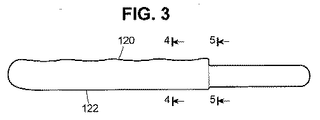
一般に骨プレートは、縦方向及び横方向の湾曲を伴って構成される。その結果骨プレートは、身体構造の湾曲に対して完全にフィットする。第1縦長プレート102は、上縦方向曲面120及び下縦方向曲面122を有する。第2縦長プレートは、より小さい上縦方向曲面130及び下縦方向曲面128を有し、連続して縦方向に湾曲させて骨プレート組立部品を摺動させる。
As best seen with reference to FIGS. 2, 4 and 6, the
In general, bone plates are constructed with longitudinal and lateral curvature. As a result, the bone plate fits perfectly against the curvature of the body structure. The first
図2中に示されたように、第1縦長プレートのプロング及びプレートは、補強するロッド又は管124によって補強されてもよい。このロッド又は管124は、チタニウム,ステンレス鋼又はプロング及び/又はプレートを補強し強化するその他の材料から作られてもよい。
As shown in FIG. 2, the prongs and plates of the first elongated plate may be reinforced by reinforcing rods or
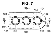
図7中に示されたように、第2縦長プレート104は、少なくとも2つの真っ直ぐなプロング孔134によって規定された端部132を有する。これらの孔は、第2縦長プレートの縦方方向の湾曲に追従しないが、第2縦長プレートの下面から開始して上面に向かって上昇する。真っ直ぐなプロング孔は、第2縦長プレートの製造をより簡単にかつより安価にする。プロングは、長手方向又は縦の湾曲を必要としないので、真っ直ぐなプロング孔は、第1縦長プレートの製造もより簡単にかつより安価にする。さらに真っ直ぐなプロング孔は、プロングがプロング孔を通じて縦方向に容易に移動することを可能にする。第2縦長プレートを例えば骨のような身体構造に固定する手段が、この第2縦長プレートの他方の端部104にある。この図示した手段は、例えば骨ネジを収容するためにねじ切りされてもよい孔142である。孔140は、好ましくは示されたように凹形にされ、上縁部148から開始して窪まされ、下縁部150に向かって湾曲されて、骨ネジの頭及びそこに含まれる連結手段を収容するポケットを形成する。
As shown in FIG. 7, the second
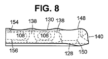
図8中で分かるように、プロング孔134,骨ネジ用の凹形ポケット及び以下で説明するセットネジ用の孔132の組み合わせは、円柱構造138をもたらす。これらの円柱構造138は、骨プレート全体及び骨ネジ及びセットネジによって成される固定を強くする。
As can be seen in FIG. 8, the combination of the
第2縦長プレートの位置決めされた隣接端部132は、ロック機構である。この実施の形態では、このロック機構は、セットネジ用の少なくとも1つのネジ山付き孔152から構成される。ネジ山付き孔152は、示されたように上縁部154及び下縁部156によって規定されたポケット内で凹形にされている。図9中で分かるように、プロング孔134は、内面136を有する。プロングがプロング孔内に設置され、セットネジがネジ山付き孔152内に螺入された場合、このセットネジが、プロングを分離し、これらのプロングを内面136に対して加圧し、これらのプロングを穴内でロックし、そして組み合わせた骨プレートの縦方向の長さを固定する。この固定は、セットネジを緩めて外し、孔内のプロングの位置を再調節することによって容易に調節されてもよい。セットネジの頭は、好ましくは凹部を有する。ネジを回して固定するか又はこの固定を再調節するため、この凹部は、スクリュードライバーのような標準工具に適合できる。
The positioned adjacent end 132 of the second vertically long plate is a locking mechanism. In this embodiment, the locking mechanism comprises at least one threaded
図1,6A,6B及び7中に示されたように、縦長プレートの端部は、ロックスロット126のような手段を備える。縦長プレートの一緒の移動をアシストするため、このロックスロット126は、プレート組立部品によって提供された締結手段によって係合されてもよい。骨ネジをどこに位置決めするかを決定するため、外科医は、使用中に組み合わせた骨プレートを骨折した骨の上に置く。その後にその外科医は、縦長プレートのうちの一方の縦長プレートを骨折した骨の片側に固定し、次いでプレート組立部品を開き、プロングを孔から外側に移動させ、そして他方の縦長プレートを自由にする。次いでこの他方の縦長プレートは、骨折した骨の他方の片側上に置かれる。骨ネジ又はその他の手段が、この縦長プレートを骨から保護する。その後に骨の表面が、プロングをプロング孔内に挿入することによって寄せ集められ、2つの縦長プレートを一緒に移動させる。外科医は、この過程の間にプロング間の観察窓を通じて骨折した骨の縁部を見ることによって寄せ集まる骨折した骨の縁部を注意深く観察してもよい。
As shown in FIGS. 1, 6 </ b> A, 6 </ b> B and 7, the end of the elongated plate is provided with means such as a
図10は、本発明の摺動する骨プレートの別の実施の形態を示す。図10中では、第1縦長プレート内のネジ山付き孔114が、ドッグボーンプレート構造を使用することによってこの縦長プレートの長手方向に対して角度を成しかつ互いに広く間隔をあけて位置決めされている。第2縦長プレート内の骨ネジ用のネジ山付き孔142が同様に指向されている。この構造は、外科医が骨ネジを縦長プレートの各端部で互いに「斜めに打ち込む」こと及びこれらの骨ネジが引き出されないことを大いに保証することを可能にする。
FIG. 10 shows another embodiment of the sliding bone plate of the present invention. In FIG. 10, the threaded
図1〜9の実施の形態に関連する図8中で分かるように、プロング孔134は、骨ネジ孔142のポケットと交差する。縦長プレート104aを縦長プレート102にロックするため、ネジ160のネジ山162が、孔152aのネジ山に係合した時に、プロング108が、孔内に挿入され、ネジのさらなる回転が上部144を押しつぶし、そして縦長プレートの底部146が、孔内のプロングをロックする。
As can be seen in FIG. 8 associated with the embodiment of FIGS. 1-9, the
図14は、ロッドを示す。このロッドは、スロット及び孔104aを有するプレートから縦長プレート102のような上述したロック機構を使用するプロング付き縦長プレートを製造するために使用されてもよい。ロッド166は、曲面168を有してもよい。この曲面168は、縦長プレート102のプロングの曲面135に類似する。2つの縦長プレート104a,2つのラージトップセットネジ160及び2つのロッド166を使用して、噛み合って調節可能な長さの骨プレートが、例えば2つのプロングを一方の縦長プレート104aの孔内に設置し、これらのプロングをラージトップセットネジでロックすることによって組み合わせできる。プロング168が、湾曲部168を有する場合、これらのプロングが、第2縦長プレートの孔内に挿入されると、延在するプロングの湾曲部168が、骨ネジ孔142用の凹形ポケットの曲面に整合するように、これらのプロングが、孔内に設置される。
FIG. 14 shows the rod. This rod may be used to produce a pronged vertical plate using the locking mechanism described above, such as the
示された好適な実施の形態では、第1縦長プレートは2つのプロングを有する。しかしながら、2つより多いプロングが利用されてよいことが理解される。図1〜9中に示された実施の形態では、ロック孔152が1つだけ示されている。図10中には、2つのロック孔が示されている。本発明の摺動する骨プレートのロック機構は、外科医が使用するための多数のネジ山孔152を有してもよいことが分かる。さらに任意の数の骨ネジ孔114及び142が、外科医によって使用される第1縦長プレート及び第2縦長プレートのそれぞれに設けられてもよい。デザインに関するその他のバリエーションが、当業者に対して自明である。
In the preferred embodiment shown, the first longitudinal plate has two prongs. However, it is understood that more than two prongs may be utilized. In the embodiment shown in FIGS. 1-9, only one
図11〜34は、本発明のさらなる実施の形態を示す。例えば図15〜21中に示されたように、この骨プレート組立部品(つまり、摺動する骨プレート組立部品)200は、第1縦長プレート201及び第2縦長プレート202から構成される。代表的な縦長プレートが、図11及び12中にさらに特に示されている。この実施の形態では、各縦長プレート201/202は、第1端部203,第2端部204,前側面205及び後側面206を有する。
FIGS. 11-34 show further embodiments of the present invention. For example, as shown in FIGS. 15 to 21, the bone plate assembly 200 (that is, the sliding bone plate assembly) 200 includes a first vertically
図11及び12並びに図15〜21中に示されたように、第1端部203は、縦長プレートの前側面205と後側面206とから等間隔の上円弧点207を有する側面湾曲部を有してもよい。第1端部は、上円弧点207周りのロックスロット126から構成される。さらに第1端部は、第1端部上縦方向曲面208及び第1端部下縦方向曲面209から構成される。
As shown in FIGS. 11 and 12 and FIGS. 15 to 21, the
各縦長プレートの前側面205は、前側面上縦方向曲面210及び前側面下縦方向曲面211から構成される。また、各長手プレートの後側面206は、後側面上縦方向曲面212及び後側面下縦方向曲面211から構成される。前側面上縦方向曲面210,前側面下縦方向曲面211,後側面上縦方向曲面212及び後側面下縦方向曲面211は、第1端部上縦方向曲面208及び第1端部下縦方向曲面209と共に各縦長プレート及び連続する長手曲面を有する骨プレート組立部品を提供する。また上述したように、長手面及び側面は、骨プレートが骨構造の湾曲部に対して完全に合うことを可能にする。各長手プレートは、特に図11及び12中で示されたように、上面236及び下面237を有する。一般にこの下面は、凹面アーチ形領域238から構成される。さらにこの凹面アーチ形領域238は、骨プレートを骨構造の湾曲部に対して完全に合わせることを容易にする。
第2端部は、平坦でもよいが、好ましくは凹形である。各縦長プレートは、2つ以上のロッド孔を有する。これらのロッド孔は、ロッド孔の壁及び孔端部によって規定される。例えば図11〜12及び15〜21中に示された発明の実施の形態では、第2端部が、前ロッド孔壁212a及び前ロッド孔端部212bによって規定された前ロッド孔212並びに後ロッド壁213a及び後ロッド端部213bによって規定された後ロッド孔213を有する。2つ以上のロッド孔、つまり前ロッド孔212及び後ロッド孔213は、第2端部から各縦長プレートの第2端部と第1端部との間のポイントにかけて縦方向に延在する。本発明の実施の形態では、各縦長プレート内の1つ又は両ロッド孔がねじ切りされてもよい。
The
The second end may be flat but is preferably concave. Each longitudinal plate has two or more rod holes. These rod holes are defined by the walls of the rod holes and the hole ends. For example, in the embodiment of the invention shown in FIGS. 11-12 and 15-21, the second end is a
図11〜12及び16〜21中に示されたように、各縦長プレートは、オプションでスリット214を有し、第2端部の直近にスリット開口部215を有し、第2端部のスリット開口部から各縦長プレートの第2端部と第1端部との間のポイントにかけて縦方向に延在する。スリット214は、スリット214は、スリット上壁216及びスリット下壁217を有する。スリットエンド250にかけたスリット上壁216とスリット下壁217との間のギャップがスリット214を規定する。オプションのスリットは、図11〜12及び15〜21中に示されたように3つの領域を有する。1つは、前領域218である。スリット214の前領域218を規定するこの前領域218は、側面205に前開口部を有し、前孔壁上のポイントにかけて延在し、それ故に前ロッド孔に対する前側面からスリットエンド250にかけた前孔壁内にスリット上壁216とスリット下壁217との間のギャップを提供する。第2領域は、中央領域である。この中央領域は、前領域が前ロッド孔と交差するポイントの向かい側の前ロッド孔の開口部から後ろロッド孔のポイントにかけて延在する。したがって、前ロッド孔及び後ロッド孔からスリットエンド250にかけたスリット上壁216とスリット下壁217との間のギャップが、スリット214の中央領域を規定する。第3領域であるスリット214の後領域220は、中央領域が後ロッド孔と交差するポイントの向かい側の後ロッド孔の開口部から後壁のポイントにかけて延在する。したがって、縦長プレートの後側面に対する後ロッド孔からスリットエンド250にかけたスリット上壁216とスリット下壁217との間のギャップが、スリット214の後領域220を規定する。スリット214は、好ましくは各縦長プレートの中心線に沿ってある。この中心線は、各縦長プレートの上面と下面の最下点との間の半分のポイントにある。
As shown in FIGS. 11-12 and 16-21, each longitudinal plate optionally has a
さらに各長手プレートは、1つ以上のロック手段孔及び1つ以上の骨ネジ孔を有してもよい。これらの双方は、ねじ切りされてもよい。しかしながら、本発明の一実施の形態では、骨ネジ孔が、滑らかな表面を有し、ねじ切りされていない。図11〜12及び15〜21中に示されたように、各縦長プレートは、1つのロック手段孔221及び2つの骨ネジ孔222を有する。各縦長プレートのスリットが、第2端部からロック手段孔にわたって延在し、骨ネジ孔の直近、好ましくはロック手段孔の直近の骨ネジで終わる。
Furthermore, each longitudinal plate may have one or more locking means holes and one or more bone screw holes. Both of these may be threaded. However, in one embodiment of the present invention, the bone screw hole has a smooth surface and is not threaded. Each longitudinal plate has one locking means
さらに骨プレート組立部品は、1つ以上の連結ロッド223を有する。この連結ロッド223は、一般に図14中に示されているものの、さらに特に図16,33及び34中に示されている。これらの連結ロッドは、一般に湾曲した連続する外,第1端部224及び対向する第2端部225を有するシリンダ形である。各連結ロッドは、両第1端部224及び第2端部225に凹形領域、つまり第1端部凹形領域226及び第2端部凹形領域227を有する。一般に各凹形領域は、凹形領域228a,228b及び隣接する領域229a,229b内のカットを有する。連結ロッドは、異なる縦方向の長さを有してもよい。図34中に示されたように、第1端部及び第2端部は、ねじ切りされてもよい、つまり縦長プレート内のねじ切りされたロッド孔3303に螺入するネジ山3301及び/又は以下で説明する中央プレートを有してもよい。連結ロッドが、その一方の端部又は両端部でねじ切りされてもよいことが分かる。
In addition, the bone plate assembly has one or more connecting rods 223. This connecting rod 223 is generally shown in FIG. 14, but more particularly in FIGS. These connecting rods are generally in the form of a cylinder having a curved continuous exterior, a
連結ロッドは、オプションで1つ以上のスロットを有してもよい。一般にスロットは、各ロッドの表面のポイントからこの表面の対向するポイントにかけて延在し、かつスロットの内面によって規定されるロッド内の開口部である。図中に示されたように、各ロッドは、オプションで第1スロット230a、 30b及び第2スロット231a、 231bを有する。これらのスロットは、凹形領域の平面に対して特定の角度を成してもよい。特に図33中に示されたように、連結ロッドは、図33中に示されたように1つ以上の保持ピンの孔を有してもよい。この保持ピンの孔3302は、保持ピンの孔の壁によって規定された連結ロッドの端部の直近にある。これらの壁は、つまり連続するロッドの片側から対向側のポイントにかけて連結ロッドにわたって完全に延在し、角を形成してもよい。保持するピンホール3302は、ねじ切りされてもよい。連結ロッドが、保持するピンホールを連結ロッドの一方の端部又は両端部に有してもよいことが分かる。
The connecting rod may optionally have one or more slots. In general, a slot is an opening in a rod that extends from a point on the surface of each rod to an opposing point on this surface and is defined by the inner surface of the slot. As shown in the figure, each rod optionally has a
骨プレート組立部品は、オプションで1つ以上の保持ピンを有してもよい。図16中に示されたように、保持ピン232は、第1端部233,第2端部234及びこれらの端部間の連続する外面235を有するシリンダ状の要素である。これらの保持ピンは、ねじ切りされた部分を有してもよい。例えば、保持ピンの連続する外面は、滑らかでもよいし又は保持ピンの第1端部若しくは第2端部に又は保持ピンの第1端部及び第2端部の双方に又は保持ピンの連続する全外面に沿ってネジ山を有してもよい。
The bone plate assembly may optionally have one or more retaining pins. As shown in FIG. 16, the holding
骨を骨折した患者を治療し、特定の実施の形態では1つ以上の連結ロッドを中央プレート又は縦長プレートに追加されてもよい時に、保持ピンのねじ切りは、外科医による縦長プレート及び/又は中央プレートの結合を容易にする。 When treating a patient with a broken bone and in one or more embodiments, one or more connecting rods may be added to the central plate or longitudinal plate, the retention pin threading may be performed by the surgeon's longitudinal plate and / or central plate. Making it easy to join.
各縦長プレートは、図11〜12及び15〜21中に示されたようにオプションで1つ以上の保持ピンの孔239を有してもよい。これらのピンホール239は、保持ピンの孔の壁によって規定される。これらの壁は、各縦長プレートの頂点から各縦長プレートの底面にかけて垂直に延在する。これらの保持ピンの孔は、ロック手段孔の直近にある。この実施の形態では、骨プレート組立部品は、4つの保持ピンの孔である第1保持ピン孔240,第2保持ピン孔241,第3保持ピン孔242及び第4保持ピン孔243を有する。ねじ切りされた保持ピンに螺入するため、これらの保持ピン孔は、各端部の一方,両端部又はピン孔の壁の全体に沿ってねじ切りされてもよい。本発明のこの実施の形態では、図33中に示されたように、この場合、連結ロッドが、保持ピン孔の壁によって規定された1つ以上のピン孔を有する。この連結ロッドが、これらの連結ロッドを通過する時に、保持ピン孔は、保持孔に整合する。このとき保持ピンは、縦長プレート (又は以下で説明する中央プレート)の保持ピン孔及び連結ロッドの保持ピン穴に通され得る。本発明の実施の形態では、保持ピン,保持ピン孔及び保持ピン穴がねじ切りされている。このことは、連結ロッドを縦長プレート(又は中央プレート)に対して効果的に守るか又は取り付ける。この縦長プレート(又は中央プレート)は、縦長プレート(又は中央プレート)の特定のロッド孔内の連結ロッドの移動を阻止する。
Each elongated plate may optionally have one or more
図13及び13aは、ロック手段を示す。このロック手段は、本発明の実施の形態にしたがって使用されてもよい。このロック手段は、上部分164及びネジ山部分162を有するラージトップセットネジ160から構成される。上部分164は、ネジ山部分162の直径より大きい幅つまり直径を有する。上部分は、上面164a,直径を有する上部分164b及び円錐台部分164cを備える。円錐台部分164cは、上面及び上部分の直径からネジ山部分の直径にかけて先細になった直径を有する。さらにロック手段は、このロック手段を締め付けるための工具を収容するための凹部164dを有してもよい。
図15〜21中に示された本発明の実施の形態では、骨プレート組立部品は、1つの第1縦長プレート201,1つの第2縦長プレート202,2つの連結ロッド(後方ロッド251及び前方ロッド)及び2つのラージトップセットネジ (第1ラージトップセットネジ253及び第2ラージトップセットネジ254)を有する。骨プレート組立部品は、オプションで4つの保持ピンを有してもよい。骨プレートは、連結ロッドの第1端部を第1縦長プレートの孔内に挿入し、連結ロッドの第2端部を骨プレートの第2縦長プレート内に挿入することによって組み立てられてもよい。オプションの保持ピンが使用される場合、挿入すべき保持ピンを保持ピン孔内に挿入してスロットを通過可能にするため、連結ロッド内のスロットが、保持ピン孔の直近にある。連結ロッドが、保持ピン穴を有する場合、連結ロッドが、第1縦長プレート又は第2縦長プレートの前方ロッド孔及び後方ロッド孔内で有効に保護されてもよい。このとき、連結ロッドの対向する端部が、対応するプレートのロッド孔内に摺動する。連結ロッドが、この対応するプレートに対して有効に保護されない。この代わりに、これらの連結ロッドのうちの1つの連結ロッドの一方の端部が、第1縦長プレートの後方ロッド孔内で有効に保護されてもよい。そして他方の連結ロッドのうちの一方の端部が、第2縦長プレートの前方ロッド孔内で有効に保護されてもよい。又はこれらの逆でもよい。このとき、連結ロッドの自由端部が、対向する縦長プレートの中空のロッド孔内に摺動され得る。骨プレート組立部品が以下で説明する中央プレートを有する場合、同様の手続きが使用され得る。例えば図15及び18中に示されたように組み立てた場合、骨プレート組立部品は、対向する第2端部付きの第1縦長プレート及び第2縦長プレートを有する。連結ロッドによって形成された対向する第2端部間のギャップが、観察窓299を規定する。本発明の特別な実施の形態では、縦長プレート及び中央プレートは、スリット及び/又はロック手段孔を必ずしも必要としない。後方連結ロッド及び前方連結ロッドの双方が、ねじ切りされた連結ロッド及び/又は縦長プレート又は中央プレート内の好ましくは全てねじ切りされた保持ピンに係合する保持ピン孔に整合するための保持ピン穴を有する連結ロッドによって同じ縦長プレート又は中央プレートに装着される本発明の実施の形態では、連結ロッドを縦長プレート又は中央プレートに対して取り外し可能に固定するためのロック手段を使用する必要がない。したがって、孔及びスリットのようなロック手段が、これらの特別な縦長プレート又は中央プレートに対して必要でない。しかしながら、1つの連結ロッドが、ねじ切りされた端部に螺入されて又は保持ピン穴を使用して装着され、かつ、縦長プレート又は中央プレートの他方のロッド孔が中空である実施の形態では、縦長プレート及び/又は中央プレートは、スリット及びロック手段孔を有しなければならない。
13 and 13a show the locking means. This locking means may be used in accordance with an embodiment of the present invention. This locking means comprises a large
In the embodiment of the invention shown in FIGS. 15-21, the bone plate assembly comprises one first
特に図21中に示されたように、縦長プレート内のロック手段孔の各々が、上セグメント244及びねじ切りされたセグメント245を有し、さらに円錐台セグメント246を有する。この円錐台セグメント246は、上セグメントの直径からねじ切りされたセグメントの直径にかけて先細になる。ロック手段孔は、一般に球形であり、以下で説明するセグメントの壁を含むロック手段孔の壁によって規定される。各縦長プレート及び各骨プレートは、ロック手段孔に係合する1つ以上のロック手段を有してもよい。上セグメント244,円錐台セグメント246及び下セグメント245の寸法は、ラージトップセットネジの寸法に一致する。その結果、上セグメントは、ラージトップセットネジの上部分に対応し、円錐台セグメントは、ラージトップセットネジの円錐台部分に対応し、そしてねじ切りされたセグメントは、ラージトップセットネジのねじ切りされた部分に対応する。その結果、ロック手段孔内に螺入された時のラージトップセットネジが、縦長プレートの上面と同一平面になる。つまりラージトップセットネジが、縦長プレートの凹部内に収容される。図21中に示されたのと同様に、各骨ネジ孔は、セグメントの壁を含む骨ネジ孔の壁によって規定される。各骨ネジ孔は、上セグメントの直径から下セグメントの直径にかけて先細になる円錐台セグメントの直径を有する上セグメント247,円錐台セグメント248及び下セグメント249を持つ。これらのセグメントは、ラージトップセットネジ及びロック手段孔に関して上述したのと同様に骨ネジの形に一致する。その結果、骨ネジ孔内に螺入された時に、骨ネジの上面が、縦長プレートの上面と同一平面上になるか又はほぼ同一平面上になる。その結果、骨ネジが、縦長プレートの凹部内に収容される。同様に、骨ネジが、骨ネジ孔に固定され、患者の骨も固定される。
In particular, as shown in FIG. 21, each of the locking means holes in the elongated plate has an
本発明のさらなる実施の形態が、図22〜29中に示されている。この実施の形態では、骨プレート組立部品300が、1つ以上の連結ロッド223の端部又はその他の中央プレートからの連結ロッドを収容するための中央プレート301を有する。この実施の形態では、骨プレート300は、第1縦長プレート,第2縦長プレート及びこれらのプレートに関連するその他の要素も有する、つまり図11〜21中に示された本発明の実施の形態に関連して上述したようなロック手段,オプションの保持ピンも有する。中央プレートは、少なくともロッド孔の壁によって規定された1つ以上、2つ以上程度のロッド孔を有してもよい。中央プレートは、例えば2つ以上の第1端部ロッド孔及び2つ以上の第2端部ロッド孔を有する。これらの第1端部ロッド孔は、第1端部から第1端部と第2端部との間の地点にかけて延在してもよい。これらの第1端部ロッド孔は、第1端部ロッド孔の内壁及び第1端部ロッド孔の端部壁によって規定される。第2端部ロッド孔は、第2端部から第1端部と第2端部との間の地点にかけて延在してもよい。これらの第2端部ロッド孔は、第2端部ロッド孔の内壁及び第2端部ロッド孔の端部壁によって規定される。また2つ以上の第1端部ロッド孔及び2つ以上の第2端部ロッド孔の位置では、中央プレートが、連続する2つ以上のロッド孔を有してもよい。これらの連続するロッド孔は、第1端部から第2端部にかけて延在する。各ロッド孔は、連続するロッド孔の壁によって規定される。各ロッド孔は、第1開口部を中央プレートの第1端部に有し、第2開口部を中央プレートの第2端部に有する。少なくとも1つのロッド孔が、ねじ切りされた連結ロッドに螺入するためにねじ切られてもよい。例えば中央プレートの第1端部の1つのロッド孔がねじ切りされてもよいし、中央プレートの第2端部の1つのロッド孔がねじ切りされてもよいし、又は、ねじ切りされた連続するロッド孔から成る実施の形態を含む中央プレートの全てのロッド孔がねじ切られてもよい。
A further embodiment of the invention is shown in FIGS. In this embodiment, the
特に図27及び28中に示されたように、例えば中央プレートが、第1端部302及び第2端部303を有する。図24及び25中に示されたように、中央プレート300は、上面304及び底面305を有する。さらに中央プレートは、前方縦長側面306及び後方縦長側面307を有する。縦長プレートの側面と同様に、中央プレートの前方縦長側面は、中央プレートの前方上縦長曲面308及び中央プレートの前方下縦長曲面309を有する。そして中央プレートの後方縦長側面は、中央プレートの後方上縦長曲面310及び中央プレートの後方下縦長曲面311を有する。上述したように、縦方向の表面及び横方向の表面のカーブ形状は、骨プレートが骨構造の湾曲に完全に合うことを可能にする。一般に中央プレートの下面も、凹状のアーチ部分を有する。さらにこのアーチ部分は、骨構造の湾曲に対する骨プレートの完全な適合を容易にする。
In particular, as shown in FIGS. 27 and 28, for example, the central plate has a
図22〜29中に示された中央プレートを有する本発明の実施の形態では、中央プレートが、少なくとも2つ、例えば2つのロック手段孔,第1端部302に対して直近の第1ロック手段孔312及び第2端部303に対して直近の第2ロック手段孔313を有する。中央プレートの第1手段孔及び第2手段孔は、同じ形であり、縦長プレートに関して上述したロック手段孔に類似の特徴を有する。さらに中央プレートは、2つ以上、例えば3つのネジ孔314a,314b,314cを有する。これらのネジ孔314a,314b,314cは、第1骨ネジ孔と第2骨ネジ孔との間の横にあり、縦長プレートの骨ネジ孔に関して上述したような同じ形及び構造を有する。
In the embodiment of the invention having a central plate shown in FIGS. 22-29, the central plate has at least two, for example two locking means holes, first locking means closest to the
中央プレートは、オプションでスリットを中央プレートの両端部に有するか又はスリットを一方の端部に有する。特に図27を参照すると、中央プレートは、第1スリット315を中央プレートの第1端部に有する。さらに中央プレートは、第1端部前方ロッド孔317及び第1端部後方ロッド孔318を有する。第1端部前方ロッド孔317は、第1ロック手段孔312の隣の骨ネジ孔314aに縦方向に直近の中央プレートの第1端部から延在する。第1端部後方ロッド孔318も、第1ロック手段孔312の隣の骨ネジ孔314aに縦方向に直近の中央プレートの第1端部から延在する。第1スリット及び第2スリットは、縦長プレート内のスリットに関して上述したような同じ形,構造及び規定する要素を有する。例えば第1スリットは、第1スリット開口部390を第1端部に有し、第1スリット上壁321と第1スリット下壁322と第1スリット端部323とによって規定され、3つの部分である第1前方部分319,第2中央部分320及び第3後方部分から構成される。第1前方部分319は、前方開口部を前方縦長側面306に有し、第1端部前方ロッド孔317上の地点にかけて延在する。第2中央部分320は、この地点に対向する第1端部前方ロッド孔上の開口部から延在する。この場合、前方領域は、第1端部後方ロッド孔318上の地点にかけて第1端部前方ロッド孔317を横断する。第3後方部分は、この地点に対向して第1端部後方ロッド孔318上の開口部から延在する。この場合、中央部分は、後方縦長側面307上の地点にかけて第1端部後方ロッド孔を横断する。第1スリット上壁321と第1下壁322との間のギャプ及び第1スリット端部323が、第1スリット315を規定する。この第1スリット315は、好ましくは各中央部分の中心線に沿ってある。この中心線は、上面と中央プレートの下面の縦長面との間の途中の地点にある。
The central plate optionally has slits at both ends of the central plate or has a slit at one end. With particular reference to FIG. 27, the central plate has a
特に図28を参照すると、この中央プレートは、第2スリット316を中央プレートの第2端部303に有する。さらに中央プレートは、第2端部前方ロッド孔324及び第2端部後方ロッド孔325を有する。第2端部前方ロッド孔324は、第2ロック手段孔313の隣の骨ネジ孔314cに縦方向に直近の中央プレートの第2端部から延在する。第2端部後方ロッド孔325も、第2ロック手段孔313の隣の骨ネジ孔314cに縦方向に直近の中央プレートの第2端部から延在する。上述したように、第1スリット及び第2スリットは、縦長プレート内のスリットに関して上述したような同じ形,構造及び規定要素を有する。例えば第2スリットは、第2スリット開口部391を第2端部に有し、第2スリット上壁326及び第2スリット下壁327によって規定される。第2スリット端部328は、3つの領域である第1前方部分329,第2中央部分330及び第3後方部分331を有する。第1前方部分329は、前方開口部を前方縦長側面306に有し、第2端部前方ロッド孔324の地点にかけて延在する。第2中央部分330は、前方部分が第2端部前方ロッド孔324に交差する地点に対向する第2端部前方ロッド孔324の開口部から第2端部後方ロッド孔325の地点にかけて延在する。第3後方部分331は、中央部分が第2端部後方ロッド孔に交差する地点に対向する第2端部後方ロッド孔325の開口部から後方縦長側面307の地点にかけて延在する。第2スリット上壁326と第2スリット下壁327と第2スリット端部329との間のギャップが、第2スリット316を規定する。第2スリット316は、好ましくは各中央部分の中心線に沿ってある。この中心線は、上面と中央プレートの下面の縦長面との間のほぼ途中の地点にある。
Referring specifically to FIG. 28, the center plate has a
上述したように、中央プレートは、連続するロッド孔を各端部に有する。したがって本発明の実施の形態では、中央プレートは、第1端部の第1開口部及び第2端部の第2開口部を有する前方縦長側面306に直近の連続する前方ロッド孔を有し、一般にシリンダ状の形状の連続する前方ロッド孔の壁によって規定される。この壁は、連続する前方ロッド孔の第1開口部から第2開口部まで延在する。この実施の形態では、同様に中央プレートも、第1端部の第1開口部及び第2端部の第2開口部を有する中央プレートの後方縦長側面307に直近の後方前方ロッド孔を有し、一般にシリンダ状の連続する後方ロッド孔の壁によって規定される。この壁は、連属する後方ロッド孔の第1開口部から第2開口部にかけて延在する。この実施の形態では、第1スリット及び第2スリットの部分が、上述したように規定されるものの、連続する前方ロッド孔及び連続する後方ロッド孔に関しては第1端部前方ロッド孔,第1端部後方ロッド孔,第2端部前方ロッド孔及び第2端部後方ロッド孔と異なって規定される。
As described above, the central plate has a continuous rod hole at each end. Therefore, in an embodiment of the present invention, the central plate has a continuous front rod hole closest to the front
図23中に示されたように、中央プレートは、オプションで1つ以上、好ましくは4つの保持ピン孔331及び1つ以上、好ましくは4つの保持ピン332を有する。これらの保持ピン孔331及び保持ピン332は、縦長プレートに関して上述したのと同様に機能する。上述したように、2つ、3つ又は4つを含む1つ以上の保持ピン孔の1つ以上の保持ピン孔がねじ切りされてもよい。
As shown in FIG. 23, the central plate optionally has one or more, preferably four retaining
2つの連結ロッドが、ねじ切りされた連結ロッドによって中央プレートの一方の端部若しくは両端部の孔に取り付けられる、及び/又は、保持ピンが保持ピン孔に使用される上述した本発明の実施の形態では、スリット又はロック手段孔は不要でもよい。例えば、ロッドが両端部に取り付けられる場合、中央プレートは、スリット又はロック手段孔を有する必要がない。一方の端部の連結ロッドが、第1端部又は第2端部に取り付けられる場合、連結ロッドが取り付けられている端部が、その直近にスリット又はロック手段孔を有しない。しかしながら、スリット及びロック手段孔は、対向する端部に又は直近にあるべきである。ただ1つの連結ロッドが、1つ以上のロッド孔を両端部に有する中央プレートの片端部又は両端部に取り付けられる場合、スリット及びロック手段孔が、中央プレートの各第1端部及び第2端部の直近に必要である。 The embodiment of the invention as described above, in which two connecting rods are attached to holes at one or both ends of the central plate by threaded connecting rods and / or holding pins are used for holding pin holes Then, the slit or the lock means hole may be unnecessary. For example, if the rod is attached to both ends, the central plate need not have slits or locking means holes. When the connecting rod at one end is attached to the first end or the second end, the end to which the connecting rod is attached does not have a slit or a lock means hole in the immediate vicinity thereof. However, the slits and locking means holes should be at or close to the opposite ends. If only one connecting rod is attached to one end or both ends of the central plate having one or more rod holes at both ends, the slits and locking means holes are located at the first and second ends of the central plate. Necessary in the immediate vicinity of the department.
図23〜24中に示されたように、中央プレートは、骨プレートを組み立てるために縦長プレートに連結して使用されてもよい。図23〜24中に示された本発明の実施の形態では、縦長プレートから延在する連結ロッドの端部が、中央プレートの連結ロッド孔内に挿入されて変位して、例えば図24中に示されたように二重の観察窓334及び335を有する骨プレート333を形成する。この実施の形態は、第2後方連結ロッド及び第2前方連結ロッドを使用する。これらのロッドは、第2端部の中央プレートと第2縦長プレートとの間で連結する。1つ以上の中央プレートが使用されてもよいことを理解すべきである。この場合、骨プレートは、3つ以上の窓を有する。したがって、本発明は、2つの縦長プレートを伴う1つ以上の中央プレートを実現する。縦長プレートは、2つ以上の窓を有するか又は中央プレートの数に1をプラスした数に等しい多数の窓を有する。特に各骨折領域上に窓を提供することによって複雑骨折を治療するために使用される時に、1つ以上の中央プレートを有する両プレートが特に役に立つ。また連結ロッドは、縦長プレート又は中央プレート内のねじ切りされたロッド孔に係合する少なくとも1つのねじ切りされた端部を有してもよいし、少なくとも1つの保持ピン穴を有してもよい。これらの保持ピン穴は、縦長プレート又は中央プレート内の保持ピン孔に対応する。保持ピン孔は、ねじ切りされてもよい。
As shown in FIGS. 23-24, the central plate may be used in conjunction with an elongated plate to assemble the bone plate. In the embodiment of the present invention shown in FIGS. 23 to 24, the end of the connecting rod extending from the longitudinal plate is inserted into the connecting rod hole of the central plate and displaced, for example, in FIG. A bone plate 333 is formed having
例えば、骨が2片に骨折した場合、外科医が、1つの縦長プレートを骨折箇所のうちの一方の側面上に据え、中央プレートを骨折箇所と骨折箇所との間の骨の上に据え、そして他方の縦長プレートを第2骨折箇所の他方の側面の骨の上に据える。これらのプレートは、各縦長プレート及び中央プレート内の1つ以上の骨ネジによって骨に固定される。骨折箇所は、骨が一緒に移動する方向に縦長プレート及び/又は中央プレートを移動させることによって寄せ集められ得る。次いでこれらの縦長プレート及び/又は中央プレートが、ラージトップセットネジを螺入することによって定位置に固定され得る。次いで、望ましい場合は、外科医が、さらなる骨ネジを使用できる骨ネジ孔に螺入する。いろいろな長さの連結ロッドが、患者の骨の2カ所以上の骨折箇所にさらに順応するために使用されてもよいし、連続する連結ロッド孔を有する中央プレートの使用に順応するために使用されてもよい。 For example, if the bone breaks into two pieces, the surgeon places one longitudinal plate on one side of the fracture site, the central plate on the bone between the fracture site, and The other longitudinal plate is placed on the bone on the other side of the second fracture site. These plates are secured to the bone by one or more bone screws in each longitudinal and central plate. The fracture site can be gathered by moving the longitudinal plate and / or the central plate in the direction in which the bones move together. These longitudinal plates and / or center plates can then be fixed in place by screwing large top set screws. Then, if desired, the surgeon threads into a bone screw hole where additional bone screws can be used. Various lengths of connecting rods may be used to further accommodate two or more fracture locations in the patient's bone, or may be used to accommodate the use of a central plate with continuous connecting rod holes. May be.
本発明の実施の形態では、骨ネジが、縦長プレートをさらに据えてもよく、そして使用される時には連結ロッドを縦長プレート又は中央プレートの後側及び/又は前側に向けて押し出すことによって中央プレートを適切にさらに据えてもよい。連結ロッドの凹部が、骨ネジ孔、好ましくは上セグメント247及び/又は円錐台セグメント248に隣接して配置されてもよいし、又は、連結ロッドの凹部の好ましくは一部が、上セグメント247及び/又は円錐台セグメント248内に配置されてもよい。その結果、凹部の一部が、骨ネジ孔を包囲する。骨ネジが、骨ネジ孔内に挿入されて骨ネジ孔に螺入する時に、側面に直近の連結ロッドが側面に向かって押され、後側面に直近の連結ロッドが後側面に向かって押される。この場合、連結ロッドと連結ロッド孔の内面との間の摩擦力が増大する。例えば図16では、骨ネジ孔250,251が、骨ネジ孔の上セグメント247及び/又は円錐台セグメント248の上に配置される連結ロッドの凹部を示す。骨ネジが、骨ネジ孔内に挿入される場合、後方連結ロッドが、縦長プレートの後側面に向かって押され、前方連結ロッドが、縦長プレートの前側面に向かって押される。その結果、連結ロッドと連結ロッド孔の内面との間の摩擦力が増大する。図24は、上述したような骨ネジ孔の一部の上に配置された連結ロッド孔の凹部を有する骨ネジ孔336,337,338,339を示す。
In an embodiment of the invention, the bone screw may further position the longitudinal plate, and when used, the central plate is pushed out by pushing the connecting rod towards the back and / or the front side of the longitudinal plate or the central plate. It may be set further appropriately. The concavity of the connecting rod may be disposed adjacent to the bone screw hole, preferably the
またラージトップセットネジ及び骨ネジに関しては、ロック手段孔及び骨ネジ孔の構造が、上述したようにラージトップセットネジ及び骨ネジの構造に係合するので、ラージトップセットネジ及び骨ネジは、縦長プレートの上面と同一平面になり、使用される時は中央プレートと同一平面になる。したがって、ラージトップセットネジ及び縦長プレート及び中央プレート内の骨ネジカウンターシンクが、縦長プレート及び/又は中央プレート内に凹部を形成する。このことは、トグルの阻止及び骨の捩れを支援する。 As for the large top set screw and the bone screw, the structure of the locking means hole and the bone screw hole engages with the structure of the large top set screw and the bone screw as described above. It is flush with the top surface of the vertical plate and when used, it is flush with the central plate. Thus, the large top set screw and the bone screw countersink in the longitudinal and central plates form a recess in the longitudinal and / or central plate. This helps to prevent toggle and twist the bone.
本発明は、連結ロッド孔内で変位できる連結ロッドを有する骨プレートに関して上述したが、連結ロッドが、縦長プレート及び/又は中央プレートの一端又は両端に固定又は一体化されてもよいことが理解されるべきである。本発明の実施の形態では、このことは、少なくとも1つの端部を有する連結ロッドを使用することによって実現されてもよい。この端部は、縦長プレート又は中央プレート内のねじ切りされた連結ロッドに係合するためにねじ切りされる。さらなる実施の形態では、このことは、少なくとも1つの保持ピン穴を有する連結ロッドで実現されてもよく、可能ならばねじ切りされた保持ピンが、縦長プレート又は中央プレートの保持ピン孔及び連結ロッドの保持ピン穴内で変位する;保持ピン孔及び保持ピン穴は選択的にねじ切りされてもよい。このような場合、縦長プレート及び/又は中央プレートは、縦長プレート及び/又は中央プレートの1つ以上の連結ロッド内で摺動できない1つ以上のロッドを有する。上述したように、連結ロッドが、縦長プレートのうちの1つの縦長プレート又は中央プレートの一端若しくは両端に取り付けられるか又は一体化される場合、ロック手段又はスロットが、縦長プレート及び/又は中央プレートのうちの少なくとも1つ又は中央プレートの一端に対して必要とされない。これらの実施の形態では、ロッドが、永続的に取り付けられかつ中央プレートと協働し、及び/又は、ロッド孔を有する縦長プレートが、ロック手段によって骨プレートに対する調節可能性を提供する。 Although the present invention has been described above with respect to a bone plate having a connecting rod that is displaceable within the connecting rod hole, it is understood that the connecting rod may be fixed or integrated at one or both ends of the longitudinal plate and / or the central plate. Should be. In an embodiment of the invention, this may be achieved by using a connecting rod having at least one end. This end is threaded to engage a threaded connecting rod in the longitudinal plate or central plate. In a further embodiment, this may be achieved with a connecting rod having at least one holding pin hole, and if possible a threaded holding pin may be provided on the holding pin hole and connecting rod of the longitudinal plate or the central plate. Displacement within the retaining pin hole; the retaining pin hole and the retaining pin hole may be selectively threaded. In such a case, the longitudinal plate and / or the central plate has one or more rods that cannot slide within one or more connecting rods of the longitudinal plate and / or the central plate. As mentioned above, when the connecting rod is attached to or integrated with one or both of the longitudinal plates or the central plate of the longitudinal plates, the locking means or slot is provided with the longitudinal plate and / or the central plate. It is not required for at least one of them or one end of the central plate. In these embodiments, the rod is permanently attached and cooperates with the central plate, and / or a longitudinal plate with rod holes provides adjustability to the bone plate by means of locking.
図30は、本発明のさらなる実施の形態を示す。この場合、縦長プレートは、L字形の構造を有する。この実施の形態では、縦長プレートが、第1端部401,第2端部,前側面403,後側面405及び凸部406を有する。ここで説明したその他の骨プレートのように、この縦長プレートの端部及び側面は、上縦長曲面及び下縦長曲面を有する。前側面403は、第2端部から第1端部401にかけて延在し、この第1端部401は、前側面403から凸部406にかけてほぼ垂直に延在する。凸部406湾曲部407を有する。この湾曲部407は、第1端部の後終点408から後壁405の後終点409にかけて延在する。この後壁は、第2端部402から凸部406にかけて延在し、一般に横部分412を有する。この横部分412は、前側面403及び垂直部分411に対して平行又はほぼ平行である。この垂直部分411は、或る角度を成して、好ましくは垂直に又はほぼ垂直に横部分412及び湾曲片から延在する。この湾曲片は、横部分412と垂直部分410との間にあってこれらの部分間に滑らかな湾曲を提供する。本発明のこの実施の形態の骨プレートは、凸部407に直近でかつ(図30中の414で示された)その他の骨ネジ孔に対してほぼ垂直に縦長プレートの上面から底面にかけて骨ネジ穴413を有してもよく、(図30の415のように示された)ロック手段孔を有してもよい。
FIG. 30 shows a further embodiment of the invention. In this case, the vertically long plate has an L-shaped structure. In this embodiment, the vertically long plate has a
図31は、本発明の別の実施の形態を示す。この実施の形態では、縦長プレート500が、「t字形」の構造を有する。この縦長プレートは、第1端部501及び第2端部502を有する。この第2端部502は、本発明のその他の実施の形態の縦長プレートに関して上述したような同じ構造及び特徴を有する。この 「t字形」の縦長プレートは、互いに対向する突出部,前突出部503及び後突出部504から構成される。「t字形」の縦長プレートは、前側面505及び後側面506も有する。ここで説明されたその他の骨プレートのように、この縦長プレート500の端部及び側面が、長手方向に湾曲した上曲面及び下曲面を有する。
FIG. 31 shows another embodiment of the present invention. In this embodiment, the vertically
第1端部501は、前終点508及び後終点509を有する。前側面は、一般に長手方向に第2端部から前側面の終点510にかけて延在する。後側面は、一般に第2端部から後側面の終点511にかけて延在する。前突出部503が、第1端部及び前側面に隣接し、第1端部の前終点508から前側面の終点509にかけて延在する。前突出部は、前突出部の第1湾曲部分507を有する。この第1湾曲部分507は、窪んでいてかつ前突出部の第2湾曲部分512に隣接する。前突出部の第1湾曲部分507及び前突出部の第2湾曲部分512が、連続する曲面を形成する。後側面504が、第1端部及び後側面に隣接し、第1端部の後終点509から後側面の終点511にかけて延在する。後突出部504は、後突出部の第1湾曲部分513を有する。この第1湾曲部分513は、凹状であって後突出部の突出している第2曲線部分514に隣接する。後突出部の第1湾曲部分513及び後突出部の第2湾曲部分514は、連続する曲面を形成する。
The
縦長プレート500は、上面515及び下面516を有する。縦長プレートの中心線519の直近の上面の頂点で、上面が凸状の曲面を有し、下面が凹状の曲面を有するように、縦長プレートが湾曲されている。上面から下面にかけて延在する前突出部の骨ネジ孔517が、前突出部の直近にある。上面から下面にかけて延在する後突出部の骨ネジ孔518が、後突出部の直近にある。縦長プレート500の曲面は、外科医が縦長プレートを骨折した骨の湾曲部分の上に配置することを可能にする。この縦長プレートは湾曲部分を有するので、骨ネジが、前突出部の骨ネジ孔517及び後突出部の骨ネジ孔518内に挿入される時に、これらの骨ネジの端部が、骨の地点、例えばつま先内で互いに向き合う。このことは、骨プレートの捩れを阻止し、骨ネジが骨から引き抜かれないことを大いに保証する。
The vertically
さらに縦長プレート500は、縦長プレートの中心線519の周りの第2端部の直近に(520として図31中に示された)少なくとも1つのロック手段孔を有し、ロック手段孔に直近の(後方保持ピン孔521a及び前方保持ピン孔521bとして図31中に示された)2つ以上の保持ピン孔及び保持ピンをオプションで有する。さらに縦長プレート500は、縦長プレートの中心線519の周りのロック手段孔510の直近に補足的な骨ネジ孔522をオプションで有する。
Further, the
図32は、本発明の縦長プレートの別の実施の形態を示す。この実施の形態では、縦長プレート600が、第1端部601を有する。この第1端部601は、湾曲部分を有する中央部分604によって結合された前方環状要素602及び後方環状要素603を有する。前方環状要素は、連続する側面を有する。この前方環状要素は、連続する側面を有する。この側面は、第1前方終点605から第2前方終点604にかけて延在する。その結果この側面は、円形又はほぼ円形である。同様に後方環状要素は、連続する側面を有する。この側面は、第1後方終点607から第2前方終点608にかけて延在する。中央部分は、第2前方終点604及び第1後方終点607に隣接し、第2前方終点604から第1後方終点607にかけて延在する。好適な実施の形態では、第2前方終点604及び第1後方終点607が、互いに対向する。中央部分604の側面609が、半円面を有する前方環状要素602と後方環状要素603との間の隙間を形成する湾曲部分を有する。すなわち、前方環状要素の側面,中央部分及び後方環状要素が、図32中に示された連続する湾曲面を形成する。
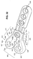
FIG. 32 shows another embodiment of the longitudinal plate of the present invention. In this embodiment, the vertically
さらに縦長プレート600は、第1前方環状片に対向する第1前方終点605から第2端部612にかけて延在する前方側面縁部610を有する。好ましくは前側面縁部は、第1前方終点605に隣接し、第2端部により直近の地点にかけて延在する第1前方縁部分613を有し、第1前方終点605の前位置から第3前方終点614のさらなる後方位置にかけて傾斜してもよい、つまり縦長プレートの中心線618に向かって傾斜してもよい。第2前方縁部分615が、第1前方縁部分613に隣接する。この第2前方縁部分615は、第4前方終点616にかけて延在する。第3前方縁部分617が、第2前方縁部分615に隣接する。この第3前方縁部分617は、一般に中心線618に対して平行である。好適な実施の形態では、第1前方縁部分613が、縦長プレートの中心線に対して傾斜し、第3前方縁部分が、一般に中心線に対して平行であるので、第2前方縁部分615は、第1前方縁部分613及び第3前方縁部分617に結合する湾曲面を提供するための湾曲部分を有してもよい。その結果、前側面縁部は、側面に結合する鋭利な縁部なしに連続する曲面を有する。
Further, the
さらに縦長プレート600は、後方環状片に対向する第2後方終点608から第2端部612にかけて延在する後側面縁部611を有する。好ましくはこの後側面縁部は、第2後方終点608に隣接し、第2端部より直近の地点にかけて延在する第1後方縁部分619を有し、第2後方終点608の後位置から第3後方終点620のより前方の位置にかけて傾斜してもよい、つまり縦長プレートの中心線618に向かって傾斜してもよい。第2後方縁部分621が、第1後方縁部分613に隣接する。この第2後方縁部分621は、第4後方終点623にかけて延在する。第3後方縁部分622が、第2後方縁部分621に隣接する。この第3後方縁部分622は、一般に中心線618に平行である。好適な実施の形態では、第1後方縁部分619が、縦長プレートの中心線に対して傾斜し、第3後方縁部分622が、一般に中心線に対して傾斜しているので、第2後方縁部分621は、第1後方縁部分619及び第3後方縁部分617に結合する曲面を提供するための湾曲部分を有してもよい。後側面は、側面に結合する鋭利な縁部なしに連続する曲面を有する。
Further, the
上述した縦長プレートのその他の実施の形態のように、縦長プレート600の端部及び側面は、縦長の上曲面及び下曲面を有する。縦長プレート600は、上面624及び下面625を有する。この縦長プレートは、オプションで湾曲している。その結果、縦長プレートの中心線618に直近の上面の頂点で、上面が凸状の構造を有し、下面が凹状の構造を有する。前方環状要素602に直近の前方骨ネジ孔626が、上面から下面にかけて延在する。後方環状要素603に直近の後方骨ネジ孔627が、上面から下面にかけて延在する。縦長プレート600の湾曲部分は、外科医が縦長プレートを骨折した骨の湾曲部分の上に配置することを可能にする。縦長プレートが、湾曲部分を有するので、骨ネジが、前方骨ネジ孔626及び後方骨ネジ孔627内に挿入される。これらの骨ネジの端部が、骨の地点、例えばつま先内で互いに向き合う。このことは、骨プレートの捩れを阻止し、骨ネジが骨から引き抜かれないことを大いに保証する。
As in the other embodiments of the vertical plate described above, the ends and side surfaces of the
さらに縦長プレート600は、縦長プレートの中心線618の周りの第2端部の直近の(628として図32中に示された)少なくとも1つのロック手段孔を有し、そしてロック手段孔に直近の(後方保持ピン孔629a及び前方保持ピン孔629bとして図32中に示された)2つ以上の保持ピン孔及び保持ピンをオプションで有する。(図30〜32中に示されたような)縦長プレート400,500及び600の実施の形態では、一般に縦長プレートは、連結ロッド孔,連結ロッド並びに連結ロッド及びその他の縦長プレート又は中央プレートに縦長プレートを固定するためのスリットのような上述した同じ特徴を有する。また、上述した全ての縦長プレート及び中央プレートは交換できる。したがって縦長プレート及び中央プレートは、連結ロッド及びロック手段を使用することによって多数の異なる種類の骨プレート組立部品に形成され得る。例えば縦長プレート600は、連結ロッドを使用することによって縦長プレート200,400又は500に結合して使用され得る。さらに1つ以上の中央プレートが、このような縦長プレートに結合して使用され得る。1つ以上の観察窓を有する骨プレート組立部品を形成するため、任意の数の様々な縦長プレート及び中央プレートが、連結ロッドと一緒に使用され得る。
Further, the
ロック手段及びロック手段孔を有する本発明の実施の形態では、ロック手段が、ロック手段孔内に挿入されて回される。その結果、ロック手段のネジ切り部分が、ロック手段孔のねじ切り部分に係合し、ロック手段が一定方向に移動される時に、このロック手段をロック手段孔内に収容させる。ラージトップセットネジが下に移動するにつれて、スリットの上壁が、スリットの下壁に向かって移動する。したがって、摩擦力が、孔の壁と連結ロッドとの間に発生する。この摩擦力は、縦長プレート及び中央プレート及び/又は連結ロッドの長手方向の移動を制限し妨げ、これによって骨プレートの長手方向の長さを設定する。スリットの下壁の全部又は一部も、上壁に向かって移動して摩擦力を発生させてもよい。その結果、ロック機構が、スリットを押しつぶし、ロック手段孔と共に縦長プレートをロッドに固定する関係を保持する。ギャップが、縦長プレートの端部間にあり、適用できる場合は縦長プレートと中央プレートとの間にあるので、これらの1つ以上のギャップは、外科医が適切な治療長さを選択する前に骨プレートを一緒に移動させる時に、その外科医が1つ以上の窓によって骨を見ることを提供する。 In an embodiment of the invention having a locking means and a locking means hole, the locking means is inserted into the locking means hole and turned. As a result, the threaded portion of the locking means engages with the threaded portion of the locking means hole, and when the locking means is moved in a certain direction, the locking means is accommodated in the locking means hole. As the large top set screw moves down, the upper wall of the slit moves toward the lower wall of the slit. Thus, a frictional force is generated between the hole wall and the connecting rod. This frictional force limits and prevents longitudinal movement of the longitudinal and central plates and / or connecting rods, thereby setting the longitudinal length of the bone plate. All or part of the lower wall of the slit may also move toward the upper wall to generate a frictional force. As a result, the lock mechanism crushes the slit and maintains the relationship of fixing the vertically long plate to the rod together with the lock means hole. Since the gap is between the ends of the longitudinal plate and, if applicable, between the longitudinal plate and the central plate, these one or more gaps are bones before the surgeon selects an appropriate treatment length. Provide the surgeon to view the bone through one or more windows as the plates are moved together.
本発明は、患者の骨折した骨を据える方法を提供する。この方法は、1つ以上の縦長プレート、オプションで1つ以上の中央プレートを提供し、1つ以上の連結ロッドを提供し、オプションで1つ以上のロック手段を提供し、1つ以上の骨ネジを提供することから成る。さらにこの方法は、骨ネジを骨ネジ孔に螺入し、この骨ネジを骨に連結することによって少なくとも1つの縦長プレートを患者の骨折した骨の第1側面に固定し、連結ロッドを第1縦長プレートの連結ロッド孔内に挿入し、第2縦長プレートを患者の骨折した骨の第2側面の上に配置し、連結ロッドを第2縦長プレート内の孔に挿入して変位させ、骨ネジを骨ネジ孔に螺入して変位させてこの骨ネジを骨に連結することによって第2縦長プレートを骨に固定し、これらの縦長プレートを互いに移動させ、そして摺動可能な骨プレート組立部品の長さを設定するロック手段を提供し作動させることから成る。さらにこの方法は、縦長プレートのさらなる骨ネジ孔に螺入して変位させることによってさらなる骨ネジを使用することから成る。オプションでは、さらにこの方法は、連結ロッド内のスロットを保持ピン孔に整合し、保持ピンを保持ピン孔及びスロット内に挿入するステップを有してもよい。本発明の別のオプションの実施の形態は、ねじ切りされた少なくとも1つの端部を有する1つ以上の連結ロッドを1つ以上の縦長プレート及び/又は中央プレートの1つ以上のねじ切りされたロッド孔に螺入することを含む。さらなる実施の形態は、1つ以上の連結ロッド内の保持ピン孔をさらなる縦長プレート及び/又は中央プレート内の保持ピン孔に整合し、保持ピンを保持ピン孔及び保持ピン穴内で変位させるステップを有する。好ましくは、ロック手段を使用するステップの前に使用される骨ネジは、連結ロッドに直近でない、つまり縦長プレート(又は中央プレート)内の骨ネジ孔内に螺入される。これらの縦長プレート(又は中央プレート)は、連結ロッドの凹部に隣接せず、及び/又は、凹部の一部を骨ネジ孔内に有しない。したがって、連結ロッドに隣接した及び/又は連結ロッドを有する骨ネジ孔は、ロック手段が適用された後の骨ネジ用に使用されてもよい。 The present invention provides a method for placing a fractured bone of a patient. This method provides one or more longitudinal plates, optionally one or more central plates, provides one or more connecting rods, optionally provides one or more locking means, and provides one or more bones Consisting of providing a screw. The method further includes fixing the at least one longitudinal plate to the first side of the fractured bone of the patient by screwing a bone screw into the bone screw hole and connecting the bone screw to the bone, and connecting the connecting rod to the first side. Insert into the connecting rod hole of the vertical plate, place the second vertical plate on the second side of the fractured bone of the patient, insert the connecting rod into the hole in the second vertical plate and displace it, bone screw A bone plate assembly that is slidable by screwing the bone screw into the bone screw hole and connecting the bone screw to the bone to secure the second longitudinal plate to the bone, moving the longitudinal plates relative to each other, and sliding Providing and actuating a locking means for setting the length. The method further comprises using additional bone screws by screwing them into the additional bone screw holes of the longitudinal plate and displacing them. Optionally, the method may further comprise the steps of aligning a slot in the connecting rod with the retaining pin hole and inserting the retaining pin into the retaining pin hole and the slot. Another optional embodiment of the present invention provides for one or more connecting rods having at least one threaded end to one or more elongated plates and / or one or more threaded rod holes in the central plate. Including screwing. Further embodiments include aligning the retaining pin holes in the one or more connecting rods with the retaining pin holes in the further longitudinal plate and / or the central plate and displacing the retaining pins within the retaining pin holes and the retaining pin holes. Have. Preferably, the bone screw used before the step of using the locking means is screwed into a bone screw hole in the longitudinal plate (or central plate) that is not proximate to the connecting rod. These longitudinal plates (or center plates) do not adjoin the recesses of the connecting rod and / or do not have a portion of the recesses in the bone screw holes. Thus, bone screw holes adjacent to and / or having a connecting rod may be used for bone screws after the locking means has been applied.
さらにこの方法は、1つ以上の中央プレートを使用することから成る。この実施の形態では、1つの中央プレートが、骨折の第2側面の上に配置され、追加の連結ロッドが、使用され中央プレートの第2端部の連結ロッド孔内に挿入される。次いで追加の中央プレート又は第2の縦長プレートが、連結ロッドを中央プレートの第2端部から骨プレート組立部品のさらなる中央プレート又は第2縦長プレートの連結ロッド孔内に変位させることによって適用されてもよい。例えば中央プレート及び追加の連結ロッドを使用するステップが、連結ロッドを中央プレートの第2端部から別の中央プレートの第1端部内に挿入することによって骨折した骨の上で繰り返され得る。外科医は、縦長プレート及び中央プレートの組み合わせ又は中央プレート及び中央プレートの組み合わせを骨に適応される各骨片の組み合わせとして移動させて固定してもよいし又は全ての骨片の組立部品が適用された後であるがロック手段が適用される前に移動させて固定してもよい。どんな場合でも、中央プレートが骨の上に配置された後に、この中央プレートは、骨ネジによって骨に固定されてもよい。 The method further comprises using one or more central plates. In this embodiment, one central plate is placed over the second side of the fracture and an additional connecting rod is used and inserted into the connecting rod hole at the second end of the central plate. An additional central plate or second longitudinal plate is then applied by displacing the connecting rod from the second end of the central plate into a further central plate of the bone plate assembly or the connecting rod hole of the second longitudinal plate. Also good. For example, the step of using a central plate and an additional connecting rod can be repeated on the fractured bone by inserting the connecting rod from the second end of the central plate into the first end of another central plate. The surgeon may move and fix the combination of the longitudinal plate and the central plate or the combination of the central plate and the central plate as a combination of bone fragments adapted to the bone, or all bone fragment assemblies are applied. However, it may be moved and fixed before the locking means is applied. In any case, after the central plate is placed over the bone, the central plate may be secured to the bone with bone screws.
連結ロッドが1以上の縦長プレート及び/又は中央プレートに永久に取り付けられる方法も、本発明の範囲内にある。したがって、縦長プレート及び/又は中央プレートを取り付け、連結ロッドそしてその他の縦長プレート及び/又は中央プレートを挿入するよりもむしろ、外科医は、縦長プレート及び/又は中央プレートを永久に取り付けられた連結ロッドに取り付け、次いで第2中央プレート及び/又は第2縦長プレートを骨折の他方の側面上に配置し、永久に取り付けられた連結ロッドを連結している中央プレート及び/又は縦長プレートの連結ロッド孔内で変位させてもよいし、又は第1縦長プレート及び/又は中央プレートを骨折の一方の側面に取り付け、次いで第2縦長プレート及び/又は中央プレートの永久に取り付けられた連結ロッドを第1縦長プレート又は中央プレートの連結ロッド孔内で変位させ、次いで第2縦長プレート又は中央プレートを骨折の向かい側の骨に取り付けてもよい。好適な方法では、外科医が、ネジ山付き端部又は保持ピン穴を有する連結ロッドを、縦長プレートの前方ロッド孔又は後方ロッド孔に取り付けるか又は縦長プレートの前方ロッド孔若しくは前方ロッド孔から離れた中央プレートの一方の端部に取り付けるか又は中央プレートの空所の端部に取り付ける。次いで外科医は、ネジ山付き端部又は保持ピン穴を有する連結ロッドを第2縦長プレートの前方ロッド孔又は後方ロッド孔内に取り付けるか又は第2縦長プレートの前方ロッド孔又は後方ロッド孔から離れた中央プレートの端部に取り付けるか及び/又は中央プレートの空所の端部に取り付ける。次いで外科医は、第1縦長プレート又は中央プレートを骨折した骨の一方の側面上に配置し、第2縦長プレート又は中央プレートを骨折した骨の他方の側面上に配置し、連結ロッドを縦長プレート又は中央プレートから向かい合った縦長プレート又は中央プレートのロッド孔の空所内で変位させる。例えば骨プレート組立部品が、第1縦長プレート及び第2縦長プレートから構成される場合、連結ロッドが、第1縦長プレートの前方ロッド孔に取り付けられ、連結ロッドが、第2縦長プレートの後方ロッド孔に取り付けられ、又は、連結ロッドが、第1縦長プレートの後方ロッド孔及び第2縦長プレートの前方ロッド孔に取り付けられる。 It is also within the scope of the present invention for the connecting rod to be permanently attached to one or more longitudinal plates and / or the central plate. Thus, rather than attaching a longitudinal plate and / or central plate and inserting a connecting rod and other longitudinal plates and / or central plate, the surgeon attaches the longitudinal plate and / or central plate to the permanently attached connecting rod. In the connecting rod hole of the central plate and / or the longitudinal plate connecting the second central plate and / or the second longitudinal plate on the other side of the fracture and connecting the permanently attached connecting rod Or the first longitudinal plate and / or the central plate may be attached to one side of the fracture, and then the second longitudinal plate and / or the permanently attached connecting rod of the central plate may be attached to the first longitudinal plate or Displacement in the connecting rod hole of the central plate, then the second longitudinal plate or central plate The door may be attached to the bone of the opposite side of the fracture. In a preferred method, the surgeon attaches a connecting rod having a threaded end or retaining pin hole to the front or rear rod hole of the longitudinal plate or away from the front or front rod hole of the longitudinal plate. Attach to one end of the center plate or to the end of the center plate cavity. The surgeon then attaches a connecting rod having a threaded end or retaining pin hole within the anterior or posterior rod hole of the second oblong plate or leaves the anterior or posterior rod hole of the second oblong plate. Attach to end of center plate and / or attach to end of cavity in center plate. The surgeon then places the first longitudinal plate or the central plate on one side of the fractured bone, places the second longitudinal plate or the central plate on the other side of the fractured bone, and connects the connecting rod to the longitudinal plate or It is displaced in the void of the longitudinal plate facing the center plate or the rod hole of the center plate. For example, when the bone plate assembly is composed of a first vertically long plate and a second vertically long plate, the connecting rod is attached to the front rod hole of the first vertically long plate, and the connecting rod is the rear rod hole of the second vertically long plate. Or a connecting rod is attached to the rear rod hole of the first vertically long plate and the front rod hole of the second vertically long plate.
これらの方法では、外科医が、縦長プレート及び/又は中央プレートを治療のために一緒に骨折した骨に移動させる。外科医は、連結ロッド並びに1)縦長プレートの第2端部,2)縦長プレートの第2端部及び中央プレートの第1端部,3)縦長プレートの第2端部及び中央プレートの第2端部及び4)中央プレートの第1端部及び中央プレートの第2端部の全て又はそのうちの幾つかによって規定された観察窓のような1つ以上の観察窓を通じて骨片を観察しなければならない。 In these methods, the surgeon moves the longitudinal plate and / or the central plate to the fractured bone together for treatment. The surgeon can connect the connecting rod and 1) the second end of the longitudinal plate, 2) the second end of the longitudinal plate and the first end of the central plate, 3) the second end of the longitudinal plate and the second end of the central plate. And 4) the bone fragment must be observed through one or more observation windows, such as an observation window defined by all or some of the first end of the central plate and the second end of the central plate .
本発明の摺動する骨プレート及び縦長プレート及び中央プレートは、ステンレス鋼又はチタニウム又はチタニウム合金のような十分な構造強度及び耐久性で知られた生物互換性のある適切な材料から構成されてもよい。このような材料の一例は、ASTM-136チタニウム合金(Ti 5AL-4V )である。このASTM-136チタニウム合金は、バナジウム又は全てのASTM材を含むチタニウム合金である。さらに、本発明の摺動する骨プレート及び縦長プレート及び中央プレートは、PEEK(ポリエチル エチルケトン)のような高分子材料又は補強材のような重合体若しくはその他の物質から製造されてもよい。材料は、通常の骨の微細運動を疑似するために十分に曲がりかつ骨の成長を刺激しなくてはならない;セラミックで充填された生物互換性のある重合体又は十分な強度の生物互換性のある物質は、治療中の骨を安定化し又は骨折した骨を矯正しなければならない。 The sliding bone plate and the longitudinal plate and the center plate of the present invention may be constructed of suitable biocompatible materials known for sufficient structural strength and durability, such as stainless steel or titanium or titanium alloys. Good. An example of such a material is ASTM-136 titanium alloy (Ti 5AL-4V). This ASTM-136 titanium alloy is a titanium alloy containing vanadium or all ASTM materials. Furthermore, the sliding bone plate and the longitudinal plate and the center plate of the present invention may be made of a polymer material such as PEEK (polyethyl ethyl ketone) or a polymer such as a reinforcing material or other material. The material must bend sufficiently to simulate normal bone micromotion and stimulate bone growth; biocompatible polymers filled with ceramics or biocompatible polymers of sufficient strength Some substances must stabilize the bone being treated or correct the fractured bone.
さらに骨プレート組立部品,縦長プレート及び/又は中央プレートは、インプラント可能なモジュール式薬物投与装置のような生物吸収薬物投与装置を有する。骨組組立部品,縦長プレート及び/又は中央プレートで使用される生物吸収薬物投与装置の例は、共同出願である2005年5 月23日に出願した米国特許第11/135,256号明細書のINPLANTABLE PROSTHETIC DEVICES CONTAINING TIMED RELEASE THERAPEUTIC AGENTS中に記されている。この明細書は、ここではそのまま引用して記載されている。例えばこのような装置は、薬物投与骨のような提供された骨又は1つ以上の縦長プレート及び/又は中央プレート内の薬物又はナノリリース内に配置されてもよく又は1つ以上の縦長プレート及び/又は中央プレートの骨ネジ孔又はロック手段孔内に配置されてもよい。 Furthermore, the bone plate assembly, the longitudinal plate and / or the central plate have a bioabsorbable drug delivery device such as an implantable modular drug delivery device. Examples of bioabsorbable drug delivery devices used in frame assemblies, vertical plates and / or center plates are shown in INPLANTABLE PROSTHETIC DEVICES in US patent application Ser. No. 11 / 135,256 filed May 23, 2005, which is a joint application. It is written in CONTAINING TIMED RELEASE THERAPEUTIC AGENTS. This specification is incorporated herein by reference in its entirety. For example, such a device may be placed in a provided bone, such as a drug-administered bone, or one or more longitudinal plates and / or drugs or nanoreleases in a central plate, or one or more longitudinal plates and It may also be arranged in a bone screw hole or locking means hole in the central plate.
生物吸収材料から成る生物吸収外科ファスナー又は骨ネジが、骨プレート組立部品、つまり縦長プレート及び/又は中央プレートに適用するために使用されてもよい。ここではそのまま引用して記載されている、例えば共同出願中の2004年12月29日に出願された米国特許第11/025,231号明細書であるSURGICAL FASTENERS AND RELATED IMPLANT DEVICES HAVING BIOABSORBABLE COMPONENTS中に記された物質は、骨ネジに使用されてもよい。骨ネジは、共同出願に記された外科ファスナーでもよい。 Bioabsorbable surgical fasteners or bone screws made of bioabsorbable material may be used to apply to the bone plate assembly, ie the longitudinal plate and / or the central plate. It is described here as it is, for example, in SURGICAL FASTENERS AND RELATED IMPLANT DEVICES HAVING BIOABSORBABLE COMPONENTS, which is the specification of U.S. Patent No. 11 / 025,231 filed on December 29, 2004. Materials may be used for bone screws. The bone screw may be a surgical fastener described in a joint application.
これまで優れた骨プレート、例えば考えられる全ての目的及び利点を網羅する摺動する骨プレート組立部品を示し説明した。しかしながら、好適な実施の形態を開示する明細書及び添付図面を考慮した場合、本発明の多くの変化,変更,バリエーション,その他の用途及び用途が、当業者にとって自明である。このような全ての変化,変更,バリエーション,その他の用途及び用途は、本発明の思想及び範囲から離れることなく特許請求の範囲だけによって制限される本発明によってカバーされる。 So far, an excellent bone plate has been shown and described, for example a sliding bone plate assembly covering all possible purposes and advantages. However, many variations, modifications, variations and other uses and uses of the invention will be apparent to those skilled in the art when considering the specification and the accompanying drawings disclosing preferred embodiments. All such changes, modifications, variations and other uses and uses are covered by the invention, which is limited only by the claims without departing from the spirit and scope of the invention.
100 骨プレート組立部品
102 第1縦長プレート
104 第2縦長プレート
106 端部
108 プロング
110 観察窓
112 端部
114 ネジ山付き貫通孔
116 上縁部
118 下縁部
120 上縦方向曲面
122 下縦方向曲面
124 ロッド,補強管
126 ロックスロット
128 下縦方向曲面
130 上縦方向曲面
132 端部,孔
134 プロング孔
135 曲面
136 内面
142 ネジ山付き孔
144 上部
146 底部
148 上縁部
150 下縁部
152 ネジ山付き孔,ロック孔
160 ネジ
162 ネジ山
164 上領域
166 ロッド
168 曲面,湾曲部
200 骨プレート組立部品
201 第1縦長プレート
202 第2縦長プレート
203 第1端部
204 第2端部
205 前側面
206 後側面
207 上円弧点
208 湾曲面
209 湾曲面
210 湾曲面
211 湾曲面
212 湾曲面,前ロッド孔
213 後ロッド孔
214 スリット
215 スリット開口部
216 スリット上壁
217 スリット下壁
218 前領域
219 中央領域
220 後領域
221 ロック手段孔
222 骨ネジ孔
223 連結ロッド
224 第1端部
225 第2端部
226 第1端部凹形領域
227 第2端部凹形領域
300 中央プレート
302 第1端部
303 第2端部
304 上面
305 底面
306 前方縦長側面
307 後方縦長側面
308 前方上縦長曲面
309 前方下縦長曲面
310 後方上縦長曲面
311 後方下縦長曲面
312 第1ロック手段孔
313 第2ロック手段孔
315 第1スリット
316 第2スリット
317 第1端部先方ロッド孔
318 第1端部後方ロッド孔
321 第1スリット上壁
322 第1スリット下壁
324 第2端部前方ロッド孔
325 第2端部後方ロッド孔
326 第2スリット上壁
327 第2スリット下壁
329 第1前方部分
330 第2中央部分
331 第3後方部分,保持ピン孔
232 保持ピン
233 第1端部
234 第2端部
235 外面
236 上面
237 下面
238 凹面アーチ形領域
239 保持ピンの孔
240 第1保持ピン孔
241 第2保持ピン孔
242 第3保持ピン孔
243 第4保持ピン孔
244 上セグメント
245 ねじ切りされたセグメント
246 円錐台セグメント
247 上セグメント
248 円錐台セグメント
249 下セグメント
250 スリットエンド,前方ロッド
251 後方ロッド
253 第1ラージトップセットネジ
254 第2ラージトップセットネジ
299 観察窓
300 骨プレート組立部品
303 第2端部
307 後方縦長側面
312 第1ロック手段孔
313 第2ロック手段孔
316 第2スリット
317 第1端部前方ロッド孔
318 第1端部後方ロッド孔
319 第1前方部分
320 第2中央部分
321 第1スリット上壁
322 第1スリット下壁
323 第1スリット端部
324 第2端部前方ロッド孔
325 第2端部後方ロッド孔
326 第2スリット上壁
327 第2スリット下壁
328 第2スリット端部
329 第1前方部分
331 第3後方部分,保持ピン孔
332 保持ピン
333 骨プレート
334 観察窓
335 観察窓
390 第1スリット開口部390
391 第2スリット開口部
3301 ネジ山
3302 保持ピンの孔
3303 ねじ切りされたロッド孔
401 第1端部
402 第2端部
403 前側面
405 後側面,後壁
406 凸部
407 湾曲部,凸部
408 後終点
411 垂直部分
412 横部分
413 骨ネジ穴
414 骨ネジ穴
415 ロック手段孔
500 縦長プレート
501 第1端部
502 第2端部
503 前突出部
504 後突出部
505 前側面
506 後側面
507 第1湾曲部分
508 前終点
509 終点
510 終点
511 終点
512 第2湾曲部分
513 第1湾曲部分
514 第2湾曲部分
515 上面
516 下面
517 骨ネジ孔
518 骨ネジ孔
519 中心線
520 ロック手段孔
521 保持ピン孔
522 骨ネジ孔
600 縦長プレート
601 第1端部
602 前方環状要素
603 後方環状要素
604 中央部分
605 第1前方終点
607 第1後方終点
608 第2前方終点
609 側面
610 前方側面縁部
612 第2端部
613 第1前方縁部分
614 第3前方終点
615 第2前方縁部分
616 第4前方終点
617 第3前方縁部分
618 中心線
619 第1後方縁部分
620 第3後方終点
621 第2後方縁部分
622 第3後方縁部分
624 上面
625 下面
626 前方骨ネジ孔
627 後方骨ネジ孔
628 ロック手段孔
100 Bone plate assembly 102 First longitudinal plate 104 Second longitudinal plate 106 End 108 Prong 110 Observation window 112 End 114 Threaded through hole 116 Upper edge 118 Lower edge 120 Upper longitudinal curved surface 122 Lower longitudinal curved surface 124 Rod, reinforcing tube 126 Lock slot 128 Lower longitudinal curved surface 130 Upper longitudinal curved surface 132 End, hole 134 Prong hole 135 Curved surface 136 Inner surface 142 Threaded hole 144 Upper portion 146 Bottom portion 148 Upper edge portion 150 Lower edge portion 152 Thread portion With hole, lock hole 160 Screw 162 Thread 164 Upper region 166 Rod 168 Curved surface, curved portion 200 Bone plate assembly 201 First vertical plate 202 Second vertical plate 203 First end 204 Second end 205 Front side 206 Rear Side surface 207 Upper arc point 208 Curved surface 209 Curved surface 21 Curved surface 211 Curved surface 212 Curved surface, front rod hole 213 Rear rod hole 214 Slit 215 Slit opening 216 Slit upper wall 217 Slit lower wall 218 Front region 219 Central region 220 Rear region 221 Lock means hole 222 Bone screw hole 223 Connecting rod 224 First end 225 Second end 226 First end concave region 227 Second end concave region 300 Center plate 302 First end 303 Second end 304 Top surface 305 Bottom surface 306 Front vertical side surface 307 Back vertical Side surface 308 Front upper longitudinal curved surface 309 Front lower longitudinal curved surface 310 Rear upper longitudinal curved surface 311 Rear lower longitudinal curved surface 312 First locking means hole 313 Second locking means hole 315 First slit 316 Second slit 317 First end forward rod hole 318 First end rear rod hole 321 First slit upper wall 322 First slit Wall 324 Second end front rod hole 325 Second end rear rod hole 326 Second slit upper wall 327 Second slit lower wall 329 First front portion 330 Second central portion 331 Third rear portion, holding pin hole 232 Holding Pin 233 First end 234 Second end 235 Outer surface 236 Upper surface 237 Lower surface 238 Concave arcuate region 239 Holding pin hole 240 First holding pin hole 241 Second holding pin hole 242 Third holding pin hole 243 Fourth holding pin Hole 244 Upper segment 245 Threaded segment 246 Frustum segment 247 Upper segment 248 Frustum segment 249 Lower segment 250 Slit end, forward rod 251 Rear rod 253 First large top set screw 254 Second large top set screw 299 Observation window 300 Bone plate assembly 303 second end 307 Back Longitudinal Side 312 First Locking Hole 313 Second Locking Hole 316 Second Slit 317 First End Front Rod Hole 318 First End Back Rod Hole 319 First Front Part 320 Second Center Part 321 First Slit Upper wall 322 First slit lower wall 323 First slit end 324 Second end forward rod hole 325 Second end rear rod hole 326 Second slit upper wall 327 Second slit lower wall 328 Second slit end 329 First 1 front part 331 3rd rear part, holding pin hole 332 holding pin 333 bone plate 334 observation window 335 observation window 390 first slit opening 390
391
Claims (57)
このプレート組立部品は、第1縦長プレート及び第2縦長プレートを有し、この第1縦長プレートは、少なくとも2つの間隔をあけた縦長のプロングによって規定された端部を有し、その他方の端部が、このプレートを身体構造に固定する手段を有し、
第2縦長プレートは、少なくとも2つの真っ直ぐな縦長孔から構成される端部を有し、各孔は、1つのプロングを受けるために適合され、その他方の端部が、このプレートを身体構造に固定する手段を有し、
これらのプロングは、プレート組立部品の長さを調節するためにこれらの真っ直ぐな孔内で変位可能であり、かつ観察窓をプロングとプレートとの間に規定し、さらにプレート組立部品は、プレート組立部品の長さを固定するロック機構を有するプレート組立部品。 In a plate assembly having an adjustable length and an elongated curved portion,
The plate assembly includes a first longitudinal plate and a second longitudinal plate, the first longitudinal plate having an end defined by at least two spaced longitudinal prongs and the other end. The part has means to secure the plate to the body structure;
The second oblong plate has an end made up of at least two straight oblong holes, each hole adapted to receive one prong and the other end to attach the plate to the body structure. Having means for fixing,
These prongs are displaceable within these straight holes to adjust the length of the plate assembly and define an observation window between the prong and the plate, and the plate assembly is A plate assembly part having a lock mechanism for fixing the length of the part.
これらのプレートのうちの一方のプレートが、少なくとも2つの間隔をあけた縦長プロングによって規定された端部を有し、これらのプレートのうちの他方のプレートが、少なくとも2つの真っ直ぐな縦長孔を有し、これらの縦長孔は、長手方向に変位するプロングを受けるために適合され、観察窓をプロングとプレートとの間に規定し、この場合
さらに組立部品は、プロングをこれらの位置のうちの1つの位置の孔内でロックするロック機構から構成され、この孔は、内面を有し、ロック機構は、プロングを内面に対して押圧する整形外科装置。 In an orthopedic device having an elongated plate assembly having an adjustable length and two ends, each of these ends may be used to connect the ends to a body structure, in which case the assembly The part is composed of two longitudinal plates, which can be displaced longitudinally with respect to each other through a plurality of positions and are fixed to each other at one of these positions, thereby increasing the length of the assembly part. Make it adjustable,
One of these plates has an end defined by at least two spaced longitudinal prongs and the other of these plates has at least two straight longitudinal holes. These longitudinal holes are adapted to receive longitudinally displaced prongs, and define an observation window between the prongs and the plate, in which case the assembly further attaches the prongs to one of these positions. An orthopedic device that consists of a locking mechanism that locks in a hole in one position, the hole having an inner surface that presses the prongs against the inner surface.
第1縦長プレートが、骨折箇所の片側の骨の上にあり、第2縦長プレートが、骨折箇所の上側の骨の上にあるように、プレート組立部品を骨の骨折箇所の上に配置し、
第1縦長プレートを骨の上に取り付け、
第2縦長プレートを移動させてプロングを骨から変位させ、そしてこの第2縦長プレートを骨折箇所の他方の側面上の骨に取り付け、
第1縦長プレートのプロングを第2縦長プレートの孔内に挿入し、間隔をあけたプロングによって形成された窓を通じて骨折箇所を観察する間に、これらのプロングを孔を通じて変位させて2つの骨片を骨折箇所で一緒にし、
これらのプロングを骨内でロックして、プレートの長さ及び骨折箇所の骨の位置を固定することから成る方法。 A method of attaching at least two bone fragments over a fracture site by attaching the plate assembly according to claim 11 over the bone fracture site.
Placing the plate assembly over the bone fracture site such that the first longitudinal plate is over the bone on one side of the fracture site and the second longitudinal plate is over the bone above the fracture site;
Attach the first vertical plate on the bone,
Moving the second longitudinal plate to displace the prongs from the bone and attaching the second longitudinal plate to the bone on the other side of the fracture site;
While the prongs of the first longitudinal plate are inserted into the holes of the second longitudinal plate and the fracture site is observed through the window formed by the spaced prongs, these prongs are displaced through the hole to produce two bone fragments. Together at the fracture site,
A method comprising locking these prongs in the bone to fix the length of the plate and the position of the bone at the fracture site.
a)上面を有する1つ以上の縦長プレート,下面,前側面,後側面,第1端部,第2端部,ロッド孔の内壁によって規定される1つ以上のロッド孔,第2端部から第1端部と第2端部との間の地点にかけて長手方向に延在するロッド孔端部,骨ネジ孔の壁によって規定された1つ以上の骨ネジ孔及びオプションで第2端部にスリット開口部を有するスリットを備え、このスリットは、スリット上壁によって規定され、このスリット上壁は、スリット開口部から縦長プレートの第2端部と第1端部との間の地点にかけて長手方向に延在し、スリット及びスリット下壁を備え、このスリット下壁は、スリット開口部から縦長プレートの第2端部と第1端部との間の地点にかけて長手方向に延在し、
b)1つ以上の連結ロッドを備え、
c)1つ以上の観察窓を備える。 The bone plate assembly is:
a) one or more vertically long plates having an upper surface, from a lower surface, a front side surface, a rear side surface, a first end portion, a second end portion, one or more rod holes defined by an inner wall of the rod hole, from a second end portion A rod hole end extending longitudinally between a first end and a second end, one or more bone screw holes defined by a wall of the bone screw hole, and optionally a second end A slit having a slit opening, the slit being defined by a slit upper wall, the slit upper wall being longitudinally extending from the slit opening to a point between the second end and the first end of the longitudinal plate The slit lower wall extends in the longitudinal direction from the slit opening to a point between the second end and the first end of the longitudinal plate,
b) comprising one or more connecting rods;
c) Provide one or more observation windows.
a)前方連結ロッドの第2端部が、中央プレートの胃第1端部のロッド孔内にあり、後方連結ロッドの第2端部が、中央プレートの第1端部のロッド孔内にあり、
b)第2前方連結ロッドの第1端部が、中央プレートの第2端部のロッド孔内にあり、第2後方連結ロッドの第1端部が、中央プレートの第2端部のロッド孔内にあり、
c)第2前方連結ロッドの第2端部が、第2縦長プレートの前方ロッド孔内にあり、後方連結ロッドの第2端部が、第2縦長プレートの後方ロッド孔内にあり、この場合、第1観察窓は、第1縦長プレートの第2端部,中央プレートの第1端部,前方連結ロッド及び後方連結ロッドによって規定され、第2観察窓は、中央プレートの第2端部,第2縦長プレートの第2端部,第2前方連結ロッド及び第2後方連結ロッドによって規定される請求項47に記載の骨プレート組立部品。 The bone plate assembly further comprises i) a central plate having a first end and a second end, ii) a second anterior connecting rod and iii) a second posterior connecting rod, wherein the central plate is at least Having one or more rod holes defined by a wall of one rod hole,
a) The second end of the front connecting rod is in the rod hole of the stomach first end of the central plate and the second end of the rear connecting rod is in the rod hole of the first end of the central plate ,
b) The first end of the second front connecting rod is in the rod hole of the second end of the center plate, and the first end of the second rear connecting rod is the rod hole of the second end of the center plate. In
c) The second end of the second front connecting rod is in the front rod hole of the second vertical plate, and the second end of the rear connecting rod is in the rear rod hole of the second vertical plate, in this case The first observation window is defined by the second end of the first vertically long plate, the first end of the central plate, the front connecting rod and the rear connecting rod, and the second observation window is the second end of the central plate, 48. The bone plate assembly of claim 47, defined by a second end of the second longitudinal plate, a second front connecting rod, and a second rear connecting rod.
b)2つ以上の連結ロッドを提供し、
c)第1縦長プレートの骨ネジ孔のうちの1つに骨ネジを螺入させ、この骨ネジを骨に連結することによって、この第1縦長プレートを骨折した骨の一方の側に固定し、
d)第2縦長プレートを患者の骨折した骨の他方の側に配置し、
e)連結ロッドを第1縦長プレート,第2縦長プレート又はこれらの組み合わせたもののロッド孔に挿入して変位させ、
f)第2縦長プレートの骨ネジ孔のうちの1つに骨ネジを螺入させ、この骨ネジを骨に連結することによって、第2縦長プレートを骨に固定し、
g)1つ以上の観察窓を通じて骨折した骨片の位置を観察している間に、縦長プレートを移動させ、
h)ロック手段を提供し、
i)ロック手段をロック手段孔に挿入して変位させてロック手段を作動させるステップから成る骨折した骨を据える方法。 a) providing at least two longitudinal plates, each longitudinal plate being defined by an upper surface, a lower surface, a front side, a rear side, a first end, a second end, a rod hole wall and a rod hole end; One or more rod holes, one or more bone screw holes defined by the wall of the bone screw hole, and optionally a slit having a slit opening at the second end, a slit and a slit lower wall, the slit being a slit The upper wall of the slit extends in the longitudinal direction from the slit opening to a point between the second end and the first end of the longitudinal plate, and the lower slit wall extends from the slit opening. A locking means hole extending between a point between the second end and the first end of the longitudinal plate, wherein at least one of the longitudinal plates is defined by a wall of the locking means hole Has,
b) providing two or more connecting rods;
c) fixing the first longitudinal plate to one side of the fractured bone by screwing a bone screw into one of the bone screw holes of the first longitudinal plate and connecting the bone screw to the bone. ,
d) placing a second longitudinal plate on the other side of the patient's fractured bone;
e) The connecting rod is inserted into the rod hole of the first vertically long plate, the second vertically long plate, or a combination thereof and displaced.
f) fixing the second longitudinal plate to the bone by screwing a bone screw into one of the bone screw holes of the second longitudinal plate and connecting the bone screw to the bone;
g) while observing the position of the fractured bone fragment through one or more observation windows, moving the longitudinal plate;
h) providing locking means;
i) A method of placing a fractured bone comprising the step of inserting and displacing the locking means into the locking means hole to actuate the locking means.
Applications Claiming Priority (2)
| Application Number | Priority Date | Filing Date | Title |
|---|---|---|---|
| US10/975,296 US7621914B2 (en) | 2004-10-28 | 2004-10-28 | Adjustable bone plate |
| PCT/US2005/038637 WO2006049998A1 (en) | 2004-10-28 | 2005-10-24 | Adjustable bone plate |
Publications (2)
| Publication Number | Publication Date |
|---|---|
| JP2008518659A true JP2008518659A (en) | 2008-06-05 |
| JP2008518659A5 JP2008518659A5 (en) | 2008-10-02 |
Family
ID=36317307
Family Applications (1)
| Application Number | Title | Priority Date | Filing Date |
|---|---|---|---|
| JP2007539080A Pending JP2008518659A (en) | 2004-10-28 | 2005-10-24 | Adjustable bone plate |
Country Status (9)
| Country | Link |
|---|---|
| US (1) | US7621914B2 (en) |
| EP (1) | EP1807011A4 (en) |
| JP (1) | JP2008518659A (en) |
| KR (1) | KR20070091118A (en) |
| CN (2) | CN101849855A (en) |
| AU (1) | AU2005302550B2 (en) |
| CA (1) | CA2585505A1 (en) |
| NZ (1) | NZ554308A (en) |
| WO (1) | WO2006049998A1 (en) |
Cited By (1)
| Publication number | Priority date | Publication date | Assignee | Title |
|---|---|---|---|---|
| KR101834075B1 (en) | 2016-06-07 | 2018-03-02 | 김정엽 | Installation method for hanger type bone fixing module |
Families Citing this family (42)
| Publication number | Priority date | Publication date | Assignee | Title |
|---|---|---|---|---|
| US20060129151A1 (en) * | 2002-08-28 | 2006-06-15 | Allen C W | Systems and methods for securing fractures using plates and cable clamps |
| US9615866B1 (en) | 2004-10-18 | 2017-04-11 | Nuvasive, Inc. | Surgical fixation system and related methods |
| US8394130B2 (en) | 2005-03-17 | 2013-03-12 | Biomet C.V. | Modular fracture fixation system |
| US8062296B2 (en) | 2005-03-17 | 2011-11-22 | Depuy Products, Inc. | Modular fracture fixation plate system with multiple metaphyseal and diaphyseal plates |
| US20070123881A1 (en) * | 2005-10-26 | 2007-05-31 | Ralph James D | Off-set bone plates |
| US8262710B2 (en) * | 2006-10-24 | 2012-09-11 | Aesculap Implant Systems, Llc | Dynamic stabilization device for anterior lower lumbar vertebral fusion |
| US8206390B2 (en) * | 2006-11-02 | 2012-06-26 | Warsaw Orthopedic, Inc. | Uni-directional ratcheting bone plate assembly |
| EP2101667B1 (en) * | 2006-12-27 | 2018-07-11 | D.L.P. | Osteosynthesis device comprising a support with an internally bored orifice associated with a bearing surface for receiving an anchoring rod |
| US20090043341A1 (en) * | 2007-08-09 | 2009-02-12 | Aesculap, Inc. | Dynamic extension plate for anterior cervical fusion and method of installation |
| US8388663B2 (en) | 2007-09-13 | 2013-03-05 | Stryker Spine | Dynamic cervical plate |
| US8343154B2 (en) * | 2007-09-26 | 2013-01-01 | Biomet C.V. | Modular bone plate system |
| WO2009055537A1 (en) * | 2007-10-23 | 2009-04-30 | K2M, Inc. | Dynamic cervical plate |
| EP2397093B1 (en) | 2007-11-02 | 2015-12-02 | Biomet C.V. | Elbow fracture fixation system |
| US9345517B2 (en) * | 2008-02-02 | 2016-05-24 | Globus Medical, Inc. | Pedicle screw having a removable rod coupling |
| US8267973B2 (en) * | 2008-02-27 | 2012-09-18 | Shoulder Options, Inc. | Fixable suture anchor plate and method for tendon-to-bone repair |
| DE102008015435B4 (en) * | 2008-03-22 | 2010-05-27 | Fette Gmbh | Konusrändelwerkzeug |
| US8808333B2 (en) * | 2009-07-06 | 2014-08-19 | Zimmer Gmbh | Periprosthetic bone plates |
| USD734853S1 (en) | 2009-10-14 | 2015-07-21 | Nuvasive, Inc. | Bone plate |
| US8449585B2 (en) * | 2009-11-05 | 2013-05-28 | K2M, Inc. | Semi-constrained bone screw |
| US10342583B2 (en) | 2010-10-01 | 2019-07-09 | K2M, Inc. | Dynamic plate with inserts |
| US8992579B1 (en) | 2011-03-08 | 2015-03-31 | Nuvasive, Inc. | Lateral fixation constructs and related methods |
| US9017409B2 (en) | 2011-04-22 | 2015-04-28 | K2M, Inc. | Spinal interbody spacer with semi-constrained screws |
| ES2613689T3 (en) * | 2011-06-17 | 2017-05-25 | Biedermann Technologies Gmbh & Co. Kg | Modular bone plate and member of such a modular bone plate |
| US9381048B2 (en) * | 2011-08-31 | 2016-07-05 | DePuy Synthes Products, Inc. | Devices and methods for cervical lateral fixation |
| US11123117B1 (en) * | 2011-11-01 | 2021-09-21 | Nuvasive, Inc. | Surgical fixation system and related methods |
| US9060815B1 (en) | 2012-03-08 | 2015-06-23 | Nuvasive, Inc. | Systems and methods for performing spine surgery |
| US9113968B2 (en) | 2013-01-28 | 2015-08-25 | Nextremity Solutions, Inc. | Dynamic bone plate compression device and method |
| DE102013104887B4 (en) * | 2013-05-13 | 2021-03-18 | Aap Implantate Ag | Osteosynthesis plate and segment for an osteosynthesis plate |
| US9579128B2 (en) | 2013-07-19 | 2017-02-28 | K2M, Inc. | Translational plate and compressor instrument |
| CN103462679A (en) * | 2013-08-26 | 2013-12-25 | 吴春生 | Movable bone connecting plate |
| US9517089B1 (en) | 2013-10-08 | 2016-12-13 | Nuvasive, Inc. | Bone anchor with offset rod connector |
| US11253299B2 (en) | 2013-10-28 | 2022-02-22 | Jace Medical, Llc | Orthopaedic fixation devices, systems and methods |
| CN104287818B (en) * | 2014-10-29 | 2017-04-19 | 刘忠军 | Length-adjustable vertebral plate |
| EP3381410A1 (en) * | 2017-03-31 | 2018-10-03 | Waldemar Link GmbH & Co. KG | Connection sleeve for two anchoring shafts of two side-to-side prostheses |
| CN110338897A (en) * | 2018-04-03 | 2019-10-18 | 李益香 | A kind of adjustable bending plate of orthopedic spinal lateral bending operation |
| FR3082417B1 (en) * | 2018-06-19 | 2021-06-25 | Arnaud Destainville | MODULAR BONE PLATE MODULE AGENCY TO RECEIVE AN ANCHORING DEVICE, MODULAR BONE PLATE THUS CONSTITUTED AND SYSTEM INCLUDING THE PLATE AND ANCHORING DEVICE |
| FR3082416B1 (en) * | 2018-06-19 | 2021-04-23 | Arnaud Destainville | MODULE AND TERMINAL MODULE FOR MODULAR BONE PLATE, MODULAR BONE PLATE THUS CONSTITUTED AND SYSTEM INCLUDING THE PLATE |
| KR102302966B1 (en) * | 2019-02-15 | 2021-09-17 | (주)메디쎄이 | Osteosynthesis plate |
| CN110279460B (en) * | 2019-07-05 | 2020-08-04 | 重庆医科大学附属永川医院 | Adjustable combined bone nail plate |
| WO2021129547A1 (en) * | 2019-12-26 | 2021-07-01 | 天津市威曼生物材料有限公司 | Special-shaped block |
| CN112294501B (en) * | 2020-10-30 | 2021-09-10 | 东南大学 | Adjustable and assembled animal vertebral body fixing instrument |
| US11331125B1 (en) * | 2021-10-07 | 2022-05-17 | Ortho Inventions, Llc | Low profile rod-to-rod coupler |
Citations (2)
| Publication number | Priority date | Publication date | Assignee | Title |
|---|---|---|---|---|
| JPH1043200A (en) * | 1996-05-31 | 1998-02-17 | Acromed Corp | Device for holding vertebra in desired space relation |
| US6689134B2 (en) * | 2002-02-13 | 2004-02-10 | Third Millennium Engineering, Llc | Longitudinal plate assembly having an adjustable length |
Family Cites Families (18)
| Publication number | Priority date | Publication date | Assignee | Title |
|---|---|---|---|---|
| KR100361341B1 (en) * | 1995-11-30 | 2003-01-24 | 신테스 아게 츄어 | Bone Lock |
| ATE309752T1 (en) * | 1997-02-11 | 2005-12-15 | Michelson Gary K | SYSTEM FOR ANTERIOR PLATING OF THE CERVICAL SPINE |
| TW415228U (en) * | 1998-04-29 | 2000-12-11 | Nat Science Council | Internal fixer for front position of the spine |
| US6136002A (en) * | 1999-02-05 | 2000-10-24 | Industrial Technology Research Institute | Anterior spinal fixation system |
| ES2274624T3 (en) * | 1999-05-14 | 2007-05-16 | Synthes Gmbh | BONE FIXING DEVICE WITH A ROTATING BOARD. |
| ATE257674T1 (en) * | 1999-09-13 | 2004-01-15 | Synthes Ag | BONE PLATE DEVICE |
| EP1205154A3 (en) * | 2000-11-08 | 2003-04-02 | Aesculap AG & Co. KG | Osteosynthesis plating apparatus and method with extension plate |
| US20050010227A1 (en) * | 2000-11-28 | 2005-01-13 | Paul Kamaljit S. | Bone support plate assembly |
| US6872210B2 (en) * | 2001-02-23 | 2005-03-29 | James P. Hearn | Sternum fixation device |
| NL1017932C2 (en) | 2001-04-24 | 2002-10-29 | Paul De Windt | Fixing device for fixing swirl parts. |
| US20040019353A1 (en) | 2002-02-01 | 2004-01-29 | Freid James M. | Spinal plate system for stabilizing a portion of a spine |
| US20040097925A1 (en) * | 2002-06-07 | 2004-05-20 | Boehm Frank H. | Cervical spine stabilizing system and method |
| US20050026168A1 (en) * | 2002-12-13 | 2005-02-03 | Genesis Group Inc. | Method for the detection of risk factors associated with myocardial infarction |
| WO2004062482A2 (en) | 2003-01-10 | 2004-07-29 | Abdou Samy M | Plating system for bone fixation and subsidence and method of implantation |
| WO2004093702A2 (en) * | 2003-04-18 | 2004-11-04 | Abdou Samy M | Bone fixation system and method of implantation |
| US7776076B2 (en) * | 2004-05-11 | 2010-08-17 | Synthes Usa, Llc | Bone plate |
| US8182518B2 (en) * | 2003-12-22 | 2012-05-22 | Life Spine, Inc. | Static and dynamic cervical plates and cervical plate constructs |
| US7993380B2 (en) * | 2005-03-31 | 2011-08-09 | Alphatel Spine, Inc. | Active compression orthopedic plate system and method for using the same |
-
2004
- 2004-10-28 US US10/975,296 patent/US7621914B2/en not_active Expired - Fee Related
-
2005
- 2005-10-24 KR KR1020077011962A patent/KR20070091118A/en active IP Right Grant
- 2005-10-24 AU AU2005302550A patent/AU2005302550B2/en not_active Ceased
- 2005-10-24 CA CA002585505A patent/CA2585505A1/en not_active Abandoned
- 2005-10-24 JP JP2007539080A patent/JP2008518659A/en active Pending
- 2005-10-24 WO PCT/US2005/038637 patent/WO2006049998A1/en active Application Filing
- 2005-10-24 CN CN201010167122A patent/CN101849855A/en active Pending
- 2005-10-24 CN CN2005800370811A patent/CN101056590B/en not_active Expired - Fee Related
- 2005-10-24 NZ NZ554308A patent/NZ554308A/en not_active IP Right Cessation
- 2005-10-24 EP EP05813057A patent/EP1807011A4/en not_active Withdrawn
Patent Citations (2)
| Publication number | Priority date | Publication date | Assignee | Title |
|---|---|---|---|---|
| JPH1043200A (en) * | 1996-05-31 | 1998-02-17 | Acromed Corp | Device for holding vertebra in desired space relation |
| US6689134B2 (en) * | 2002-02-13 | 2004-02-10 | Third Millennium Engineering, Llc | Longitudinal plate assembly having an adjustable length |
Cited By (1)
| Publication number | Priority date | Publication date | Assignee | Title |
|---|---|---|---|---|
| KR101834075B1 (en) | 2016-06-07 | 2018-03-02 | 김정엽 | Installation method for hanger type bone fixing module |
Also Published As
| Publication number | Publication date |
|---|---|
| EP1807011A1 (en) | 2007-07-18 |
| AU2005302550B2 (en) | 2011-01-27 |
| KR20070091118A (en) | 2007-09-07 |
| CN101056590B (en) | 2010-06-16 |
| CN101056590A (en) | 2007-10-17 |
| US20060100625A1 (en) | 2006-05-11 |
| WO2006049998A1 (en) | 2006-05-11 |
| EP1807011A4 (en) | 2009-07-08 |
| NZ554308A (en) | 2011-01-28 |
| AU2005302550A1 (en) | 2006-05-11 |
| US7621914B2 (en) | 2009-11-24 |
| CN101849855A (en) | 2010-10-06 |
| CA2585505A1 (en) | 2006-05-11 |
Similar Documents
| Publication | Publication Date | Title |
|---|---|---|
| JP2008518659A (en) | Adjustable bone plate | |
| US20220079578A1 (en) | Counter-torque implant | |
| US9968382B2 (en) | Spinal stabilization system and method | |
| US7695473B2 (en) | Adjustable bone plate | |
| US20210015601A1 (en) | Soft tissue fixation device | |
| AU2017216554B2 (en) | Interspinous process fusion device and method of use | |
| US20070123881A1 (en) | Off-set bone plates | |
| CA2537438A1 (en) | Bone plates with hole for interchangeably receiving locking and compression screws | |
| WO2011008739A2 (en) | Joint arthrodesis and arthroplasty | |
| JP2009529979A (en) | Modular fracture fixation plate system | |
| JP2002538931A (en) | Orthopedic surgery system with removable bone anchor | |
| US20200323568A1 (en) | An intramedullary nail system | |
| JP2008532709A (en) | Modular fracture fixation plate system | |
| JP7137792B2 (en) | Devices for treating spinous processes | |
| US11801079B2 (en) | Rotational guided growth devices, systems, and methods | |
| CA3224566A1 (en) | Bone fixation devices, systems, methods, and instruments |
Legal Events
| Date | Code | Title | Description |
|---|---|---|---|
| A521 | Written amendment |
Free format text: JAPANESE INTERMEDIATE CODE: A523 Effective date: 20080813 |
|
| A621 | Written request for application examination |
Free format text: JAPANESE INTERMEDIATE CODE: A621 Effective date: 20080813 |
|
| RD04 | Notification of resignation of power of attorney |
Free format text: JAPANESE INTERMEDIATE CODE: A7424 Effective date: 20100527 |
|
| A131 | Notification of reasons for refusal |
Free format text: JAPANESE INTERMEDIATE CODE: A131 Effective date: 20110308 |
|
| A02 | Decision of refusal |
Free format text: JAPANESE INTERMEDIATE CODE: A02 Effective date: 20110830 |