JP2008512963A - Method and apparatus for transmitting orthogonal pilot tones in a multi-antenna communication system - Google Patents
Method and apparatus for transmitting orthogonal pilot tones in a multi-antenna communication system Download PDFInfo
- Publication number
- JP2008512963A JP2008512963A JP2007531391A JP2007531391A JP2008512963A JP 2008512963 A JP2008512963 A JP 2008512963A JP 2007531391 A JP2007531391 A JP 2007531391A JP 2007531391 A JP2007531391 A JP 2007531391A JP 2008512963 A JP2008512963 A JP 2008512963A
- Authority
- JP
- Japan
- Prior art keywords
- orthogonal
- pilot tones
- transmit antennas
- pilot
- data
- Prior art date
- Legal status (The legal status is an assumption and is not a legal conclusion. Google has not performed a legal analysis and makes no representation as to the accuracy of the status listed.)
- Pending
Links
Images


Classifications
-
- H—ELECTRICITY
- H04—ELECTRIC COMMUNICATION TECHNIQUE
- H04B—TRANSMISSION
- H04B7/00—Radio transmission systems, i.e. using radiation field
- H04B7/02—Diversity systems; Multi-antenna system, i.e. transmission or reception using multiple antennas
- H04B7/04—Diversity systems; Multi-antenna system, i.e. transmission or reception using multiple antennas using two or more spaced independent antennas
- H04B7/06—Diversity systems; Multi-antenna system, i.e. transmission or reception using multiple antennas using two or more spaced independent antennas at the transmitting station
- H04B7/0613—Diversity systems; Multi-antenna system, i.e. transmission or reception using multiple antennas using two or more spaced independent antennas at the transmitting station using simultaneous transmission
- H04B7/0667—Diversity systems; Multi-antenna system, i.e. transmission or reception using multiple antennas using two or more spaced independent antennas at the transmitting station using simultaneous transmission of delayed versions of same signal
- H04B7/0669—Diversity systems; Multi-antenna system, i.e. transmission or reception using multiple antennas using two or more spaced independent antennas at the transmitting station using simultaneous transmission of delayed versions of same signal using different channel coding between antennas
-
- H—ELECTRICITY
- H04—ELECTRIC COMMUNICATION TECHNIQUE
- H04B—TRANSMISSION
- H04B7/00—Radio transmission systems, i.e. using radiation field
- H04B7/02—Diversity systems; Multi-antenna system, i.e. transmission or reception using multiple antennas
- H04B7/04—Diversity systems; Multi-antenna system, i.e. transmission or reception using multiple antennas using two or more spaced independent antennas
- H04B7/06—Diversity systems; Multi-antenna system, i.e. transmission or reception using multiple antennas using two or more spaced independent antennas at the transmitting station
- H04B7/0613—Diversity systems; Multi-antenna system, i.e. transmission or reception using multiple antennas using two or more spaced independent antennas at the transmitting station using simultaneous transmission
- H04B7/0684—Diversity systems; Multi-antenna system, i.e. transmission or reception using multiple antennas using two or more spaced independent antennas at the transmitting station using simultaneous transmission using different training sequences per antenna
-
- H—ELECTRICITY
- H04—ELECTRIC COMMUNICATION TECHNIQUE
- H04B—TRANSMISSION
- H04B7/00—Radio transmission systems, i.e. using radiation field
- H04B7/02—Diversity systems; Multi-antenna system, i.e. transmission or reception using multiple antennas
- H04B7/10—Polarisation diversity; Directional diversity
-
- H—ELECTRICITY
- H04—ELECTRIC COMMUNICATION TECHNIQUE
- H04L—TRANSMISSION OF DIGITAL INFORMATION, e.g. TELEGRAPHIC COMMUNICATION
- H04L27/00—Modulated-carrier systems
- H04L27/26—Systems using multi-frequency codes
- H04L27/2601—Multicarrier modulation systems
- H04L27/2602—Signal structure
-
- H—ELECTRICITY
- H04—ELECTRIC COMMUNICATION TECHNIQUE
- H04L—TRANSMISSION OF DIGITAL INFORMATION, e.g. TELEGRAPHIC COMMUNICATION
- H04L5/00—Arrangements affording multiple use of the transmission path
- H04L5/02—Channels characterised by the type of signal
- H04L5/023—Multiplexing of multicarrier modulation signals
-
- H—ELECTRICITY
- H04—ELECTRIC COMMUNICATION TECHNIQUE
- H04L—TRANSMISSION OF DIGITAL INFORMATION, e.g. TELEGRAPHIC COMMUNICATION
- H04L5/00—Arrangements affording multiple use of the transmission path
- H04L5/02—Channels characterised by the type of signal
- H04L5/06—Channels characterised by the type of signal the signals being represented by different frequencies
-
- H—ELECTRICITY
- H04—ELECTRIC COMMUNICATION TECHNIQUE
- H04W—WIRELESS COMMUNICATION NETWORKS
- H04W48/00—Access restriction; Network selection; Access point selection
- H04W48/08—Access restriction or access information delivery, e.g. discovery data delivery
-
- H—ELECTRICITY
- H04—ELECTRIC COMMUNICATION TECHNIQUE
- H04L—TRANSMISSION OF DIGITAL INFORMATION, e.g. TELEGRAPHIC COMMUNICATION
- H04L27/00—Modulated-carrier systems
- H04L27/26—Systems using multi-frequency codes
- H04L27/2601—Multicarrier modulation systems
- H04L27/2602—Signal structure
- H04L27/2603—Signal structure ensuring backward compatibility with legacy system
-
- H—ELECTRICITY
- H04—ELECTRIC COMMUNICATION TECHNIQUE
- H04W—WIRELESS COMMUNICATION NETWORKS
- H04W48/00—Access restriction; Network selection; Access point selection
- H04W48/16—Discovering, processing access restriction or access information
-
- H—ELECTRICITY
- H04—ELECTRIC COMMUNICATION TECHNIQUE
- H04W—WIRELESS COMMUNICATION NETWORKS
- H04W84/00—Network topologies
- H04W84/02—Hierarchically pre-organised networks, e.g. paging networks, cellular networks, WLAN [Wireless Local Area Network] or WLL [Wireless Local Loop]
- H04W84/10—Small scale networks; Flat hierarchical networks
- H04W84/12—WLAN [Wireless Local Area Networks]
Abstract
マルチ・アンテナ通信システムにおいて擬似直交パイロット・トーンを伝達するための方法および装置が提供される。データは、N個の送信アンテナを有するマルチ・アンテナ通信システムにおいて、N個の送信アンテナのそれぞれについて幾つかのパイロット・トーンを生成し、N個の送信アンテナのそれぞれを介するデータを送信することによって、送信され、N個の送信アンテナのそれぞれについてのパイロット・トーンは、互いに擬似直交している。パイロット・トーンは、一般に、データに埋め込まれる。データは、N個の送信アンテナを有するマルチ・アンテナ通信システムにおいて、N個の送信アンテナのそれぞれを介するデータを受信することによって受信され、データは、N個の送信アンテナのそれぞれについて幾つかのパイロット・トーンを含み、N個の送信アンテナのそれぞれについてのパイロット・トーンは、互いに擬似直交している。パイロット・トーンは、周波数領域、時間領域、空間領域、またはこれらの全てにおいて、直交することができる。 Methods and apparatus are provided for transmitting pseudo-orthogonal pilot tones in a multi-antenna communication system. Data is generated in a multi-antenna communication system with N transmit antennas by generating several pilot tones for each of the N transmit antennas and transmitting data via each of the N transmit antennas. The pilot tones for each of the N transmit antennas are pseudo-orthogonal to each other. Pilot tones are typically embedded in the data. Data is received in a multi-antenna communication system having N transmit antennas by receiving data via each of the N transmit antennas, and the data is several pilots for each of the N transmit antennas. -The tones are included and the pilot tones for each of the N transmit antennas are quasi-orthogonal to each other. The pilot tones can be orthogonal in the frequency domain, time domain, spatial domain, or all of these.
Description
本出願は、参照により本明細書に組み込まれている、2004年9月9日に出願した米国仮特許出願第60608472号の優先権を主張するものである。
本発明は、一般に、マルチ・アンテナ無線通信システムに関し、より詳細には、マルチ・アンテナ通信システムのための位相および周波数オフセット推定技術に関する。
This application claims priority from US Provisional Patent Application No. 60608472, filed September 9, 2004, which is incorporated herein by reference.
The present invention relates generally to multi-antenna wireless communication systems, and more particularly to phase and frequency offset estimation techniques for multi-antenna communication systems.
次世代ワイヤレス・ローカル・エリア・ネットワーク(WLAN)システムにおいて頑強性と容量の両方を増大するために、複数の送信および受信アンテナが提案されている。頑強性の増大は、複数のアンテナを有するシステムに導入された空間ダイバシティおよび追加利得を利用する技術によって実現することができる。容量の増大は、帯域幅効率の良いMIMO(多入力多出力)技術を用いるマルチパス・フェージング環境において実現することができる。マルチ・アンテナ通信システムは、複数の送信アンテナを介する別個のデータ・ストリームを送信することによって、所与のチャネル帯域幅におけるデータ・レートを増大する。各受信器は、複数の受信アンテナを介するこれらのデータ・ストリームの組合わせを受信する。 In order to increase both robustness and capacity in next generation wireless local area network (WLAN) systems, multiple transmit and receive antennas have been proposed. Increased robustness can be achieved by techniques that utilize spatial diversity and additional gain introduced in systems with multiple antennas. The increase in capacity can be realized in a multipath fading environment using bandwidth efficient MIMO (multiple input multiple output) technology. A multi-antenna communication system increases the data rate in a given channel bandwidth by transmitting separate data streams over multiple transmit antennas. Each receiver receives a combination of these data streams via multiple receive antennas.
異なるデータ・ストリームを適切に受信するために、マルチ・アンテナ通信システムにおける受信器は、トレーニングによってチャネル行列を獲得しなければならない。これは、一般に、同期およびチャネル推定を行うために特定のトレーニング・シンボルまたはプリアンブルを使用することによって実現される。プリアンブルは、受信器が、(1)自動利得制御(AGC)機能を設定するために受信信号の電力を推定すること、(2)高速フーリエ変換(FFT)ウィンドウの最適配置を実行するためにタイミングオフセットを獲得すること、(3)送信器と受信器の間の周波数オフセットを推定し、FFT復調に先立って周波数オフセットを補正すること、ならびに、(4)FFTが実行された後に直交振幅変調(QAM)シンボルをデマップするのを助けるためにチャネルの転送関数を推定することを助ける。 In order to properly receive different data streams, a receiver in a multi-antenna communication system must acquire a channel matrix by training. This is generally achieved by using specific training symbols or preambles to perform synchronization and channel estimation. The preamble is timed for the receiver to (1) estimate the power of the received signal to set up an automatic gain control (AGC) function, and (2) to perform optimal placement of the Fast Fourier Transform (FFT) window. Obtaining an offset, (3) estimating the frequency offset between the transmitter and receiver, correcting the frequency offset prior to FFT demodulation, and (4) quadrature amplitude modulation (after the FFT is performed) Help estimate channel transfer function to help demap QAM) symbols.
更に、幾つかのパイロット・トーンが、位相雑音および残留周波数オフセットを推定するために、OFDMデータ・シンボルに埋め込まれている。送信器および受信器のローカル発振器における位相雑音は、FFT出力における共通位相誤差(CPE)をもたらし、共通位相誤差は、一般に、OFDMシンボルごとに補正される必要がある。FFT入力における残留周波数オフセットもまた、CPEを作り出す。一般に、CPE推定の精度は、パイロットの数とともに増大し、それに従って、パケット・エラー率が低減し、伝送の信頼性が向上する。 In addition, several pilot tones are embedded in the OFDM data symbols to estimate phase noise and residual frequency offset. Phase noise in the transmitter and receiver local oscillators results in a common phase error (CPE) in the FFT output, which typically needs to be corrected for each OFDM symbol. A residual frequency offset at the FFT input also creates a CPE. In general, the accuracy of CPE estimation increases with the number of pilots, and accordingly the packet error rate is reduced and transmission reliability is improved.
一般に、MIMOシステムは、全てのアンテナで、同じパイロット・トーンおよび偏波系列を送信する。これらのパイロットは、確定された信号である。したがって、パイロットの幾つかの特定のビーム・パターンがある。周波数選択チャネルでは、異なるパイロット・トーンは、異なるチャネルを経験することになる。したがって、各パイロット・トーンは、異なるビーム・パターンを有する。したがって、チャネルによって幾つかのパイロットが強化される一方で、他のパイロットが打ち消されることになる。「フラット・フェージング」チャネルの事例では、ビーム形成が、より深刻であることが見られる。この事例では、全てのパイロットが、同じチャネル・フェージングを経験し、全て打ち消されうる。したがって、チャネル状態は、受信器がデータを適切に受信することを可能にしているが、パイロットが全てフェードされたため、受信器が、そのデータを処理できないことがある。 In general, a MIMO system transmits the same pilot tone and polarization sequence on all antennas. These pilots are defined signals. Thus, there are some specific beam patterns for the pilot. In a frequency selective channel, different pilot tones will experience different channels. Thus, each pilot tone has a different beam pattern. Thus, some pilots are strengthened by the channel while others are canceled. In the case of a “flat fading” channel, beamforming is seen to be more severe. In this case, all pilots experience the same channel fading and can all be canceled. Thus, the channel condition allows the receiver to properly receive the data, but the receiver may not be able to process the data because all of the pilot has been faded.
一般に、MIMOシステムは、全てのアンテナで、同じパイロット・トーンおよび偏波系列を送信する。これらのパイロットは、確定的信号である。したがって、複数の送信アンテナから所与の受信アンテナへのチャネルが、強く相関する場合、パイロットは、ファー・フィールドで特定のビーム・パターンを作り出すことになる。したがって、2次元平面での方位角に応じて、チャネルによって幾つかのパイロットが強化される一方、他のパイロットが低下させられることになる。ビーム形成は、「フラット・フェージング」チャネルの事例で最も深刻であり、そのため、チャネルが周波数に応じて変化しないことが見られる。この事例では、全てのパイロットは、同じチャネル・フェージングを経験し、特定の方位角として打ち消されうる。したがって、チャネル状態は、受信器がデータを適切に受信することを可能にしているが、パイロットに対する壊滅的なフェージングのため、受信器が、そのデータを処理できないことがある。
したがって、パイロット・トーンがチャネルにおいて互いに打ち消すことがないように、マルチ・アンテナ通信システムにおいて直交パイロット・トーンを伝達するための方法および装置が必要である。 Therefore, there is a need for a method and apparatus for communicating orthogonal pilot tones in a multi-antenna communication system so that the pilot tones do not cancel each other in the channel.
一般に、マルチ・アンテナ通信システムにおいて擬似直交パイロット・トーンを伝達するための方法および装置が提供される。本発明の一態様によれば、データは、N個の送信アンテナを有するマルチ・アンテナ通信システムにおいて、N個の送信アンテナのそれぞれについて幾つかのパイロット・トーンを生成し、N個の送信アンテナのそれぞれを介するデータを送信することによって、送信され、N個の送信アンテナのそれぞれについてのパイロット・トーンは、互いに擬似直交している。パイロット・トーンは、一般に、データに埋め込まれる。パイロット・トーンは、周波数領域、時間領域、空間領域、またはこれらの全てにおいて、直交することができる。 In general, a method and apparatus for transmitting pseudo-orthogonal pilot tones in a multi-antenna communication system is provided. According to one aspect of the present invention, data generates several pilot tones for each of the N transmit antennas in a multi-antenna communication system having N transmit antennas, Transmitted by transmitting data over each, the pilot tones for each of the N transmit antennas are quasi-orthogonal to each other. Pilot tones are typically embedded in the data. The pilot tones can be orthogonal in the frequency domain, time domain, spatial domain, or all of these.
本発明の別の態様によれば、データは、N個の送信アンテナを有するマルチ・アンテナ通信システムにおいて、N個の送信アンテナのそれぞれを介するデータを受信することによって受信され、データは、N個の送信アンテナのそれぞれについて幾つかのパイロット・トーンを含み、N個の送信アンテナのそれぞれについてのパイロット・トーンは、互いに擬似直交している。
本発明のより完全な理解、ならびに本発明の更なる特徴および利点は、以下の詳細な説明および図面を参照することによって得られる。
According to another aspect of the invention, data is received in a multi-antenna communication system having N transmit antennas by receiving data via each of the N transmit antennas, wherein the data is N pieces. Includes several pilot tones for each of the N transmit antennas, and the pilot tones for each of the N transmit antennas are quasi-orthogonal to each other.
A more complete understanding of the present invention, as well as further features and advantages of the present invention, will be obtained by reference to the following detailed description and drawings.
本発明では、例えば「フラット・フェージング」チャネルの事例に存在する、パイロット打ち消しの問題が、様々なアンテナにわたって直交パイロットを送信することによって克服できることが認められる。本発明の一態様によれば、直交パイロット設計は、周波数領域と空間領域の両方において提供される。したがって、後で更に説明するように、直交コードが、周波数および空間次元にわたりパイロット信号に使用される。周波数および空間にわたる直交パイロット信号の伝送は、ビーム形成効果を緩和させる。したがって、概してパイロットのビーム形成がない。 In the present invention, it will be appreciated that the pilot cancellation problem present, for example, in the case of “flat fading” channels can be overcome by transmitting orthogonal pilots over various antennas. According to one aspect of the invention, orthogonal pilot designs are provided in both the frequency domain and the spatial domain. Therefore, as described further below, orthogonal codes are used for pilot signals over frequency and spatial dimensions. Transmission of orthogonal pilot signals over frequency and space mitigates beamforming effects. Therefore, there is generally no pilot beamforming.
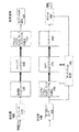
図1は、従来の802.11a/gトランシーバ100の概略ブロック図である。送信器側105では、情報ビットが、段110で、まず符号化され、次いで、段120で、周波数インターリーブされる。符号化されインターリーブされたビットは、次いで、段130で、サブキャリア(トーン)上にマップされ、周波数領域OFDM信号を形成する。段130において、周波数領域OFDM信号は、逆フーリエ変換(IFFT)によって時間領域に変換される。段140で、データはシリアル化され、各OFDMシンボルにガード・インターバルが追加される。最後に、段145において、各パケットの先頭に、トレーニングおよび信号フィールドを含むプリアンブルが追加される。
FIG. 1 is a schematic block diagram of a conventional 802.11a / g transceiver 100. At the
受信器側150では、受信信号が、最初にRFフロント・エンド155によって処理され、次いで、段160で、シリアル・データがパラレル化され、ガード・インターバルが除去される。時間領域信号は、FFT170を使用して周波数領域に変換され、サブキャリアが、符号化されインターリーブされたビットにデマップされる。それまでの間に、プリアンブルが段165で処理される。インターリーブされたビットは、段180でデインターリーブされ、段190で復号されて、送信された情報ビットを提供する。
At the receiver side 150, the received signal is first processed by the RF front end 155, and then at
図2は、例示的IEEE802.11a/gOFDMシステムのための例示的フレーム・フォーマット200を示す。図2に示すように、各フレーム200(またはパケット)は、周知の様式で受信器における正確な同期を確立するためのプリアンブル210から始まり、その後にユーザ・データ220が続く。各プリアンブル210は、ショート・プリアンブル、ロング・プリアンブル、および、信号フィールドを含む。各データ・シンボルは、4つのパイロット・トーン230を含む。前述のように、これらのパイロット・トーン230は、キャリア周波数オフセット、タイミング・ドリフト、および振幅ドループを追跡するために使用される。
FIG. 2 shows an
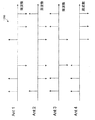
MIMOシステムでは、異なる送信器アンテナが、異なるデータOFDMシンボルを送信する。図3は、例示的SISO(1入力1出力)およびMIMOシステムにおけるデータの伝送を示す。図3に示すように、単一のアンテナを有するSISO送信器310が、単一のアンテナを有するSISO受信器320に、データを送信する。また、2つのアンテナを有する例示的MIMO送信器350が、2つのアンテナを有する例示的MIMO受信器360に、データを送信する。
In a MIMO system, different transmitter antennas transmit different data OFDM symbols. FIG. 3 illustrates transmission of data in exemplary SISO (1-input 1-output) and MIMO systems. As shown in FIG. 3, a
図4は、例示的2×2MIMOシステムのための例示的MIMOフレーム・フォーマット400を示す。図4に示すように、各フレーム400は、プリアンブル部分410およびデータ部分420を含む。例示的プリアンブル410は、レガシの802.11aプリアンブルとそれに続く専用のMIMOプリアンブルを含む。適切なプリアンブル・フォーマットの更に詳細な説明については、参照により本明細書に組み込まれている、2005年1月24日に出願した「Method and Apparatus for Preamble Training in a Multiple Antenna Communication System」という名称の米国特許出願第11043025号を参照されたい。データ伝送において、パイロット・トーンは、図2に関連し上述したようにSISOシステムと同じ方法で挿入される。したがって、パイロット・トーンは、全ての送信器アンテナから同時に送信される。
FIG. 4 shows an exemplary
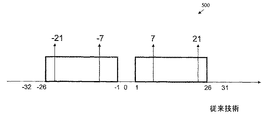
図5は、例示的20MHzモードのためのパイロット・トーンの位置500を示す。図5に示すように、合計4つのパイロットが、図2に示した802.11a/gシステムと同じ位置で(+/−7および+/−21の位置で)割り当てられている。例示的キャリア間隔は、3.125kHzである。図6は、例示的40MHzモードのためのパイロット・トーンの位置600を示す。図6に示すように、40MHzモードにおいて(+/−16、+/−30、および+/−44の位置で)合計6つのパイロットがある。キャリア間隔は、3.125kHzのままである。
FIG. 5 shows a
図7は、(全て1つのアンテナで送信される)例示的IEEE802.11a/gパイロット信号710、720、730、740についての偏波系列700を示す。全ての送信器アンテナは、パケット全体を通して同じパイロットを送信することに留意されたい。パイロット信号は、図7に示すように、時間領域においてシンボルからシンボルへと符号または偏波を変更する。例えば、第1の時間工程で、−1,+1,+1,+1が、同じアンテナで送信される。図7のコンテキストでは、用語「偏波」は、+1および−1(すなわち、180度の位相シフト)を意味する。
FIG. 7 shows a
図8は、図7の例示的偏波系列700の生成を示す。図8に示すように、偏波系列700は、初期状態「1111111」を有するスクランブラ800を使用して生成され、スクランブラ800は、出力における「0」の値を「1」に置き換え、「1」の値を「−1」の値に置き換える。
FIG. 8 shows the generation of the
一般に、MIMOシステムは、全てのアンテナで同じパイロット・トーンおよび偏波系列を送信する。パイロットは、確定的信号である。したがって、これは、同じパイロット信号が異なるアンテナから送信された場合、ビーム形成をもたらす可能性がある。図9は、パイロット901〜904のようなパイロットのビーム形成900を示す。周波数選択チャネルでは、図9の様々なチャネル応答911〜914によって示されるように、異なるパイロット・トーンは、異なるチャネルを経験する。したがって、全てのパイロットが同時にフェードするわけではない。したがって、受信されたパイロット920によって示されるように、幾つかのパイロットが強化される一方、他のパイロットが打ち消されることがある。全体として、受信器は、必要とされる機能を実行するために、相当に強い平均パイロット・エネルギを受け取ることができる。「フラット・フェージング」の事例913および914では、ビーム形成が、最も深刻であることが見られる。この事例では、全てのパイロットが、同じチャネル・フェージングを経験する。図9の受信パイロット950によって示されるように、全てのパイロットが打ち消されうる。したがって、チャネル状態は、受信器がデータを適切に受信することを可能にしているが、パイロットは全てフェードされたため、受信器が、そのデータを処理できないことがある。
In general, a MIMO system transmits the same pilot tone and polarization sequence on all antennas. The pilot is a deterministic signal. This can therefore lead to beamforming if the same pilot signal is transmitted from different antennas. FIG. 9 shows
本発明では、このパイロット打ち消しの問題が、様々なアンテナにわたって擬似直交パイロットを送信することによって克服できることが認められる。本明細書では、一般に、任意の2つのアンテナにおけるパイロット間の相互相関が小さい場合、それらのパイロットは、擬似直交であると見なされる。任意の2つのパイロット系列の相互相関が、正確にゼロの場合、それらのパイロットは直交している。任意の2つのパイロット系列の相互相関が、所定の閾値より小さい数の場合、それらのパイロットは擬似直交している。本発明の一態様によれば、直交パイロット設計は、周波数領域と空間領域の両方において提供される。 In the present invention, it is recognized that this pilot cancellation problem can be overcome by transmitting pseudo-orthogonal pilots over various antennas. In this specification, generally, if the cross-correlation between pilots at any two antennas is small, those pilots are considered quasi-orthogonal. If the cross-correlation between any two pilot sequences is exactly zero, the pilots are orthogonal. If the cross-correlation between any two pilot sequences is a number less than a predetermined threshold, the pilots are quasi-orthogonal. According to one aspect of the invention, orthogonal pilot designs are provided in both the frequency domain and the spatial domain.
複数のアンテナにわたる直交パイロットの送信
本発明の一態様によれば、空間および周波数における直交コードは、時間領域に重ね合わせられる偏波系列を有するパイロット信号のために使用される。周波数および空間にわたる直交パイロット信号の送信は、ビーム形成効果を緩和させる。
周波数直交パイロット
Transmission of orthogonal pilots across multiple antennas According to one aspect of the invention, orthogonal codes in space and frequency are used for pilot signals having polarization sequences that are superimposed in the time domain. Transmission of orthogonal pilot signals across frequency and space mitigates beamforming effects.
Frequency orthogonal pilot
前述のように、例示的20MHzモードでは、4つのパイロット・トーンがある。したがって、4つの直交コードが必要とされる。図10は、例示的4アンテナMIMOシステムのための20MHzでの周波数領域直交パイロットのセット1000を示す。図10に示すパイロット設計1000は、4×4のウォルシュ行列に基づいて、IEEE802.11a/gと同様に、2位相偏移変調(BPSK)信号をやはり使用する。アンテナ1は、ウォルシュ行列の第1行すなわち1,1,1,−1で符号化される。同様に、各後続のアンテナANT2からANT4は、ウォルシュ行列の対応する行で符号化される。図10に示すように、第1のアンテナANT1は、IEEE802.11a/gパイロット(1,1,1,−1)を送信する。残りのアンテナANT2からANT4は、第1のアンテナと直交しかつ互いに直交するパイロットを送信する。この事例では、アンテナは、それらが直交系列を作るように符号化される。
As mentioned above, in the exemplary 20 MHz mode, there are four pilot tones. Therefore, four orthogonal codes are required. FIG. 10 shows a
図11は、例示的4アンテナMIMOシステムのための20MHzでの周波数領域直交パイロットの代替のセット1100を示す。図11の例示的実施形態では、4位相偏移変調(QPSK)コンスタレーションおよびフーリエ変換系列が使用される。図11に示すように、各アンテナANT1からANT4は、フーリエ変換行列の1行を送信する。このような様式で、4つのアンテナは、互いに直交するパイロットを送信する。図11は、任意のパイロット・トーンが、4つの方向(紙の上方、下方、内方、または外方)の1つに向くことができる、3次元表現であることに留意されたい。直交系列は、図11の左側のコンスタレーションに基づいて得られる。図11のより高い次元数は、追加の自由度を伴って、より多くのパイロットを有する直交パイロット系列を選択することを容易にする。図11の例では、8個までのパイロット・トーンのパイロット系列を作成することができる。
FIG. 11 shows an
例示的40MHzモードでは、典型的には6つのパイロット・トーンがある。したがって、6つの直交コードが必要とされる。図12は、例示的4アンテナMIMOシステムのための40MHzでの周波数領域擬似直交パイロットのセット1200を示す。BPSK信号を使用するウォルシュ・コードが存在しないことに留意されたい。BPSKが利用される場合、完全には直交しないが相互相関が互いに最小限である擬似雑音(PN)系列を、識別することができる。図12の周波数領域擬似直交パイロットのセット1200は、そのようなPN系列の1つのセットである。図12の例の最小限の相互相関は、+−2であり、これは、任意の選択されたアンテナにおけるパイロット・トーンの数の2分の1未満である。
In the exemplary 40 MHz mode, there are typically six pilot tones. Therefore, six orthogonal codes are required. FIG. 12 shows a
図13は、例示的4アンテナMIMOシステムのための40MHzでの周波数領域直交パイロットの代替のセット1300を示す。40MHzでの直交コードを得るためには、フーリエ系列を利用しなければならない。図13の実装形態では、40MHzで完全に直交したパイロット・トーンを得るために、6−PSKコンスタレーションおよびフーリエ変換系列を利用する。ANT1からANT4の各アンテナは、フーリエ変換行列の1行を送信する。
FIG. 13 shows an
更なる変形形態では、6−PSKが直交パイロットを生成するために使用されるがデータ伝送において使用されないため、フーリエ系列の使用が問題となりうることが認められる。図14は、データ伝送にも使用される直交パイロットを生成するために16QAMの配置点を使用する折衷案を示す。パイロットのために(16個の使用可能な点のうちから)使用される6つの点が、図14において記号

時間直交偏波
図10から14に関連して上述した実装形態では、周波数領域で直交パイロットのセットを求める。図10から14の直交パイロット設計は、各OFDMシンボルの範囲内で、パイロットが深いフェード状態にならないことを保証する。本発明の別の態様によれば、全てのパイロットが1つのOFDMシンボルにおいて深いフェード状態であったとしても、次のOFDMシンボルにおいて深いフェード状態にならないように偏波も交替される。したがって、このような実施形態では、異なるアンテナでは偏波系列もまた異なり、かつそれらの偏波系列は直交しなければならない。
Time-Orthogonal Polarization The implementation described above with reference to FIGS. 10 to 14 determines a set of orthogonal pilots in the frequency domain. The orthogonal pilot design of FIGS. 10-14 ensures that the pilot does not go into deep fade within each OFDM symbol. According to another aspect of the invention, even if all pilots are in a deep fade state in one OFDM symbol, the polarizations are alternated so that they do not enter a deep fade state in the next OFDM symbol. Therefore, in such an embodiment, the polarization sequences are also different for different antennas and the polarization sequences must be orthogonal.
一般にパケット長は可変であることに留意されたい。したがって、全ての可能なパケット長を対象に含む直交または擬似直交系列を生成するためのスキームが必要とされる。本発明では、全ての可能なパケット長を対象に含むために、4つ以上のPN生成器が実装されて、パケット長に応じてそれらの間の切替えを行うべきであることが認められる。 Note that in general the packet length is variable. Therefore, there is a need for a scheme for generating orthogonal or pseudo-orthogonal sequences that cover all possible packet lengths. In the present invention, it will be appreciated that in order to cover all possible packet lengths, four or more PN generators should be implemented and switch between them depending on the packet length.
A. 直交偏波系列の生成
一般に、パケット内にL個のOFDMシンボルがある場合、フーリエ変換系列が、パイロット・トーンを生成するために利用され、n番目の送信器アンテナにおける1番目のOFDMシンボルは、
![]()
L=2k
として表され、(−1/Lの最大限の相関を有する)PN系列のセットは、以下のように表される。
![]()
L = 2 k
The set of PN sequences (with a maximum correlation of -1 / L) is expressed as
B. 擬似直交偏波系列の生成
図8に関連して上述したように、スクランブラ800が、偏波系列の生成のために使用される。しかし、時間領域で擬似直交偏波系列を得るために、ここでは、異なるアンテナは、異なる初期状態を使用する。一実装形態では、異なるアンテナが、異なるシフトであるが実際には同じ偏波系列を使用する。ほとんどのパケット長については、このような設計により、実際にかなり小さい相互相関が与えられる。
B. Generation of Pseudo-Orthogonal Polarization Sequence As described above with reference to FIG. 8, the
したがって、全てのアンテナに対して同じスクランブラ800が使用されるが、異なるアンテナは、異なる初期状態を使用する。例えば、例示的4アンテナMIMO実装形態では、4つのアンテナは、以下の異なる初期状態を使用することができる。
Ant1:1111111
Ant2:1010101
Ant3:1100110
Ant4:1110001
Thus, the
Ant1: 11111111
Ant2: 1010101
Ant3: 1100110
Ant4: 1110001
本明細書に示し説明した実施形態および変形形態は、本発明の原理の例示に過ぎず、本発明の範囲および精神から逸脱することなしに当業者によって様々な修正形態を実装することができることは理解されるべきである。 The embodiments and variations shown and described herein are merely illustrative of the principles of the present invention and that various modifications can be implemented by those skilled in the art without departing from the scope and spirit of the present invention. Should be understood.
Claims (26)
前記N個の送信アンテナのそれぞれについて幾つかのパイロット・トーンを生成する工程であって、前記N個の送信アンテナのそれぞれについての前記パイロット・トーンは、互いに擬似直交する工程と、
前記N個の送信アンテナのそれぞれを介する前記データを送信する工程とを含む、方法。 A method for transmitting data in a multi-antenna communication system having N transmit antennas, comprising:
Generating several pilot tones for each of the N transmit antennas, wherein the pilot tones for each of the N transmit antennas are quasi-orthogonal to each other;
Transmitting the data via each of the N transmit antennas.
データを送信するためのN個の送信アンテナを含み、前記アンテナのそれぞれは、他に対して擬似直交する幾つかのパイロット・トーンを利用する、送信器。 A transmitter in a multi-antenna communication system comprising:
A transmitter comprising N transmit antennas for transmitting data, each of which utilizes a number of pilot tones that are quasi-orthogonal to the other.
前記N個の送信アンテナのそれぞれを介する前記データを受信する工程を含み、前記データは、前記N個の送信アンテナのそれぞれについて幾つかのパイロット・トーンを含み、前記N個の送信アンテナのそれぞれについての前記パイロット・トーンは、互いに擬似直交する、方法。 In a multi-antenna communication system, a method for receiving data via at least one receive antenna transmitted by a transmitter having N transmit antennas, comprising:
Receiving the data via each of the N transmit antennas, the data including several pilot tones for each of the N transmit antennas, and for each of the N transmit antennas The pilot tones of the method are quasi-orthogonal to each other.
前記N個の送信アンテナのそれぞれを介する前記データを受信するための少なくとも1つの受信アンテナを含み、前記データは、前記N個の送信アンテナのそれぞれについて幾つかのパイロット・トーンを含み、前記N個の送信アンテナのそれぞれについての前記パイロット・トーンは、互いに擬似直交する、受信器。 A receiver for receiving data in a multi-antenna communication system having at least one transmitter having N transmit antennas, comprising:
Including at least one receive antenna for receiving the data via each of the N transmit antennas, the data including a number of pilot tones for each of the N transmit antennas; The pilot tones for each of the transmit antennas are quasi-orthogonal to each other.
Applications Claiming Priority (2)
| Application Number | Priority Date | Filing Date | Title |
|---|---|---|---|
| US60847204P | 2004-09-09 | 2004-09-09 | |
| PCT/US2005/032253 WO2006029362A1 (en) | 2004-09-09 | 2005-09-09 | Method and apparatus for communicating orthogonal pilot tones in a multiple antenna communication system |
Publications (2)
| Publication Number | Publication Date |
|---|---|
| JP2008512963A true JP2008512963A (en) | 2008-04-24 |
| JP2008512963A5 JP2008512963A5 (en) | 2008-10-30 |
Family
ID=35610009
Family Applications (1)
| Application Number | Title | Priority Date | Filing Date |
|---|---|---|---|
| JP2007531391A Pending JP2008512963A (en) | 2004-09-09 | 2005-09-09 | Method and apparatus for transmitting orthogonal pilot tones in a multi-antenna communication system |
Country Status (6)
| Country | Link |
|---|---|
| US (3) | US7558328B2 (en) |
| EP (1) | EP1787448A1 (en) |
| JP (1) | JP2008512963A (en) |
| KR (1) | KR101158153B1 (en) |
| CN (1) | CN101080907A (en) |
| WO (1) | WO2006029362A1 (en) |
Cited By (3)
| Publication number | Priority date | Publication date | Assignee | Title |
|---|---|---|---|---|
| JP2011029680A (en) * | 2008-05-29 | 2011-02-10 | Sony Deutschland Gmbh | Improved pilot allocation in multi-carrier system with notch frequency |
| JP2012518332A (en) * | 2009-02-13 | 2012-08-09 | クゥアルコム・インコーポレイテッド | Method and apparatus for orthogonal pilot tone mapping in multiple input and multiple output (MIMO) and space division multiple access (SDMA) systems |
| WO2014103170A1 (en) * | 2012-12-26 | 2014-07-03 | パナソニック株式会社 | Receiver apparatus and frequency selectivity interference correction method |
Families Citing this family (39)
| Publication number | Priority date | Publication date | Assignee | Title |
|---|---|---|---|---|
| US7366250B2 (en) * | 2004-09-09 | 2008-04-29 | Agere Systems Inc. | Method and apparatus for improved efficiency in an extended multiple antenna communication system |
| US7961828B2 (en) * | 2004-10-06 | 2011-06-14 | Motorola Mobility, Inc. | Sync bursts frequency offset compensation |
| US7881390B2 (en) * | 2004-12-01 | 2011-02-01 | Intel Corporation | Increased discrete point processing in an OFDM communication system |
| KR100657312B1 (en) * | 2005-02-26 | 2006-12-13 | 삼성전자주식회사 | Apparatus for compensating frequency offset and channel change in MIMO-OFDM receiver and method thereof |
| EP1718021B1 (en) | 2005-04-29 | 2010-03-17 | Sony Deutschland GmbH | Receiving device and communication method for an OFDM communication system with a new preamble structure |
| EP1906576B1 (en) * | 2005-08-24 | 2016-11-16 | Wi-Fi One, LLC | Mimo-ofdm transmission device and mimo-ofdm transmission method |
| GB2469229B (en) * | 2005-11-04 | 2011-02-02 | Nec Corp | Wireless communication system and method of controlling a transmission power |
| US8081687B2 (en) * | 2005-11-11 | 2011-12-20 | Broadcom Corporation | Received signal determination based upon frame classification |
| JP4802763B2 (en) * | 2006-02-28 | 2011-10-26 | カシオ計算機株式会社 | OFDM signal receiving apparatus, OFDM signal receiving method, and terrestrial digital broadcast receiving apparatus |
| US7876774B2 (en) * | 2006-09-27 | 2011-01-25 | Telefonaktiebolaget Lm Ericsson (Publ) | Contention based random access method with autonomous carrier selection |
| US20080216125A1 (en) * | 2007-03-01 | 2008-09-04 | Microsoft Corporation | Mobile Device Collaboration |
| JP2008278017A (en) * | 2007-04-26 | 2008-11-13 | Toshiba Corp | Transmission method of ofdm signal, ofdm transmitter, and ofdm receiver |
| US7729204B2 (en) * | 2007-06-08 | 2010-06-01 | Microsoft Corporation | Acoustic ranging |
| US7986738B2 (en) * | 2007-10-19 | 2011-07-26 | Redpine Signals, Inc | Peak to average power ratio reduction apparatus and method for a wireless OFDM transmitter |
| KR100914321B1 (en) * | 2007-12-03 | 2009-08-27 | 한국전자통신연구원 | Method for enbodying frame in wideband wireless communication system using multi antennas |
| US8098750B2 (en) | 2008-07-10 | 2012-01-17 | Infineon Technologies Ag | Method and device for transmitting a plurality of data symbols |
| US8774331B2 (en) * | 2011-10-31 | 2014-07-08 | Qualcomm Incorporated | System and method for single chain search with a multiple chain receiver |
| CA2861328C (en) * | 2012-02-27 | 2018-02-27 | Intel Corporation | Techniques to manage dwell times for pilot rotation |
| US9178675B2 (en) | 2012-02-27 | 2015-11-03 | Intel Corporation | Channel estimation and tracking |
| US9647863B2 (en) | 2012-02-27 | 2017-05-09 | Intel Corporation | Techniques to manage dwell times for pilot rotation |
| CN103312389B (en) * | 2012-03-06 | 2016-05-25 | 华为技术有限公司 | A kind of multiuser interference suppression method, terminal and base station |
| US8923153B2 (en) | 2012-11-02 | 2014-12-30 | Intel Corporation | Techniques to update a wireless communication channel estimation |
| US9871683B2 (en) | 2013-05-07 | 2018-01-16 | Lg Electronics Inc. | Method and device for transmitting data unit |
| US9900906B2 (en) | 2013-11-19 | 2018-02-20 | Intel IP Corporation | Method, apparatus, and computer readable medium for multi-user scheduling in wireless local-area networks |
| US9544914B2 (en) | 2013-11-19 | 2017-01-10 | Intel IP Corporation | Master station and method for HEW communication using a transmission signaling structure for a HEW signal field |
| WO2015076917A1 (en) | 2013-11-19 | 2015-05-28 | Li Guoqing C | Master station and method for hew communication with signal field configuration for hew ofdma mu-mimo wideband channel operation |
| US9271241B2 (en) | 2013-11-19 | 2016-02-23 | Intel IP Corporation | Access point and methods for distinguishing HEW physical layer packets with backwards compatibility |
| US9325463B2 (en) | 2013-11-19 | 2016-04-26 | Intel IP Corporation | High-efficiency WLAN (HEW) master station and methods to increase information bits for HEW communication |
| CN104184561B (en) * | 2014-01-13 | 2019-04-30 | 中兴通讯股份有限公司 | Precoded pilot processing method, device, base station and terminal |
| TWI578838B (en) * | 2014-04-01 | 2017-04-11 | 英特爾Ip公司 | Wireless apparatus for high-efficiency (he) communication with additional subcarriers |
| US9680603B2 (en) | 2014-04-08 | 2017-06-13 | Intel IP Corporation | High-efficiency (HE) communication station and method for communicating longer duration OFDM symbols within 40 MHz and 80 MHz bandwidth |
| US9654264B2 (en) * | 2014-05-08 | 2017-05-16 | Telefonaktiebolaget Lm Ericsson (Publ) | Beam forming using a dual polarized antenna arrangement |
| EP3143820B1 (en) | 2014-06-12 | 2022-06-29 | Huawei Technologies Co., Ltd. | Apparatus and method for ofdma tone allocation in next generation wi-fi networks |
| US20160087825A1 (en) * | 2014-09-19 | 2016-03-24 | Qualcomm Incorporated | Methods and apparatus for early detection of high efficiency wireless packets in wireless communication |
| US10411931B2 (en) | 2014-10-31 | 2019-09-10 | Lg Electronics Inc. | Method for transreceiving PPDU in wireless communication system and device for same |
| WO2016125999A1 (en) * | 2015-02-04 | 2016-08-11 | 엘지전자(주) | Method for uplink multi-user transmission in wireless communication system and device for same |
| US9621311B2 (en) * | 2015-05-08 | 2017-04-11 | Newracom, Inc. | Pilot transmission and reception for orthogonal frequency division multiple access |
| CN106533997B (en) * | 2015-09-09 | 2019-08-16 | 扬智科技股份有限公司 | The calculation method and its decoding apparatus of system signal noise ratio |
| CN112688866B (en) * | 2020-12-22 | 2023-03-21 | 上海金卓科技有限公司 | Data sending method, data receiving method, electronic equipment and storage medium |
Citations (6)
| Publication number | Priority date | Publication date | Assignee | Title |
|---|---|---|---|---|
| JP2002314464A (en) * | 2001-01-30 | 2002-10-25 | Lucent Technol Inc | Transmitter, receiver and method used for performing channel sounding |
| JP2002374224A (en) * | 2001-04-09 | 2002-12-26 | Nippon Telegr & Teleph Corp <Ntt> | Ofdm signal communication system, ofdm signal transmitting device and ofdm signal receiving device |
| JP2003283441A (en) * | 2002-03-27 | 2003-10-03 | Toshiba Corp | Signal transmission system, transmission apparatus, and receiver |
| JP2003304215A (en) * | 2002-04-09 | 2003-10-24 | Panasonic Mobile Communications Co Ltd | Ofdm communication apparatus and ofdm communication method |
| WO2004030265A1 (en) * | 2002-09-26 | 2004-04-08 | Kabushiki Kaisha Toshiba | Channel estimation for ofdm using orthogonal training sequences |
| WO2004038988A2 (en) * | 2002-10-25 | 2004-05-06 | Qualcomm, Incorporated | Pilots for mimo communication systems |
Family Cites Families (24)
| Publication number | Priority date | Publication date | Assignee | Title |
|---|---|---|---|---|
| US5805584A (en) * | 1996-02-23 | 1998-09-08 | L-3 Communications Corporation | Multi-user acquisition procedure for point-to-multipoint synchronous CDMA systems |
| US6898197B1 (en) * | 1997-02-28 | 2005-05-24 | Interdigital Technology Corporation | Geolocation of a mobile terminal in a CDMA communication system |
| US6141542A (en) | 1997-07-31 | 2000-10-31 | Motorola, Inc. | Method and apparatus for controlling transmit diversity in a communication system |
| US6901062B2 (en) * | 1999-12-01 | 2005-05-31 | Kathrein-Werke Kg | Adaptive antenna array wireless data access point |
| US6473467B1 (en) * | 2000-03-22 | 2002-10-29 | Qualcomm Incorporated | Method and apparatus for measuring reporting channel state information in a high efficiency, high performance communications system |
| US20020065047A1 (en) * | 2000-11-30 | 2002-05-30 | Moose Paul H. | Synchronization, channel estimation and pilot tone tracking system |
| KR100510434B1 (en) * | 2001-04-09 | 2005-08-26 | 니폰덴신뎅와 가부시키가이샤 | OFDM signal transmission system, OFDM signal transmission apparatus and OFDM signal receiver |
| US6614298B2 (en) * | 2001-08-13 | 2003-09-02 | Soma Networks, Inc. | Apparatus and method for controlling adaptive circuits |
| US7006557B2 (en) | 2002-01-31 | 2006-02-28 | Qualcomm Incorporated | Time tracking loop for diversity pilots |
| US7532564B2 (en) * | 2002-09-11 | 2009-05-12 | Intel Corporation | Sub-banded ultra-wideband communications systems |
| US8208364B2 (en) * | 2002-10-25 | 2012-06-26 | Qualcomm Incorporated | MIMO system with multiple spatial multiplexing modes |
| US7324429B2 (en) * | 2002-10-25 | 2008-01-29 | Qualcomm, Incorporated | Multi-mode terminal in a wireless MIMO system |
| US20040081131A1 (en) * | 2002-10-25 | 2004-04-29 | Walton Jay Rod | OFDM communication system with multiple OFDM symbol sizes |
| US7280467B2 (en) * | 2003-01-07 | 2007-10-09 | Qualcomm Incorporated | Pilot transmission schemes for wireless multi-carrier communication systems |
| US7756002B2 (en) * | 2003-01-30 | 2010-07-13 | Texas Instruments Incorporated | Time-frequency interleaved orthogonal frequency division multiplexing ultra wide band physical layer |
| US7233612B1 (en) * | 2003-02-19 | 2007-06-19 | Advanced Micro Devices, Inc. | Wireless communication deinterleaver using multi-phase logic and cascaded deinterleaving |
| US7668125B2 (en) * | 2003-09-09 | 2010-02-23 | Qualcomm Incorporated | Incremental redundancy transmission for multiple parallel channels in a MIMO communication system |
| US7421041B2 (en) * | 2004-03-01 | 2008-09-02 | Qualcomm, Incorporated | Iterative channel and interference estimation and decoding |
| US8000223B2 (en) * | 2004-04-12 | 2011-08-16 | Broadcom Corporation | Method and system for multi-antenna preambles for wireless networks preserving backward compatibility |
| US7417974B2 (en) * | 2004-04-14 | 2008-08-26 | Broadcom Corporation | Transmitting high rate data within a MIMO WLAN |
| US8285226B2 (en) * | 2004-05-07 | 2012-10-09 | Qualcomm Incorporated | Steering diversity for an OFDM-based multi-antenna communication system |
| WO2006002310A2 (en) * | 2004-06-22 | 2006-01-05 | Conexant Systems, Inc. | Legacy compatible spatial multiplexing systems and methods |
| US7978649B2 (en) * | 2004-07-15 | 2011-07-12 | Qualcomm, Incorporated | Unified MIMO transmission and reception |
| US7372913B2 (en) * | 2004-07-22 | 2008-05-13 | Qualcomm Incorporated | Pilot tones in a multi-transmit OFDM system usable to capture transmitter diversity benefits |
-
2005
- 2005-09-09 JP JP2007531391A patent/JP2008512963A/en active Pending
- 2005-09-09 EP EP05813830A patent/EP1787448A1/en not_active Ceased
- 2005-09-09 US US11/223,757 patent/US7558328B2/en active Active
- 2005-09-09 WO PCT/US2005/032253 patent/WO2006029362A1/en active Application Filing
- 2005-09-09 KR KR1020077005469A patent/KR101158153B1/en active IP Right Grant
- 2005-09-09 CN CNA2005800301402A patent/CN101080907A/en active Pending
- 2005-09-09 US US11/223,775 patent/US7477633B2/en active Active
- 2005-09-09 US US11/572,450 patent/US8964522B2/en active Active
Patent Citations (6)
| Publication number | Priority date | Publication date | Assignee | Title |
|---|---|---|---|---|
| JP2002314464A (en) * | 2001-01-30 | 2002-10-25 | Lucent Technol Inc | Transmitter, receiver and method used for performing channel sounding |
| JP2002374224A (en) * | 2001-04-09 | 2002-12-26 | Nippon Telegr & Teleph Corp <Ntt> | Ofdm signal communication system, ofdm signal transmitting device and ofdm signal receiving device |
| JP2003283441A (en) * | 2002-03-27 | 2003-10-03 | Toshiba Corp | Signal transmission system, transmission apparatus, and receiver |
| JP2003304215A (en) * | 2002-04-09 | 2003-10-24 | Panasonic Mobile Communications Co Ltd | Ofdm communication apparatus and ofdm communication method |
| WO2004030265A1 (en) * | 2002-09-26 | 2004-04-08 | Kabushiki Kaisha Toshiba | Channel estimation for ofdm using orthogonal training sequences |
| WO2004038988A2 (en) * | 2002-10-25 | 2004-05-06 | Qualcomm, Incorporated | Pilots for mimo communication systems |
Non-Patent Citations (2)
| Title |
|---|
| JPN6011044105; Imad Barhumi et.al: 'Optimal Training Design for MIMO OFDM Sytems in Mobile Wireless Channels' IEEE Transactions on Signal Processing Vol.51 No.6, 200306, pp.1615-1624 * |
| JPN6011044106; Sumei Sun et.al: 'Training Sequence Assisted Channel Estimation for MIMO OFDM' Wireless Communications and Networking, 2003. WCNC 2003. Vol.1, 200303, pp.38-43 * |
Cited By (6)
| Publication number | Priority date | Publication date | Assignee | Title |
|---|---|---|---|---|
| JP2011029680A (en) * | 2008-05-29 | 2011-02-10 | Sony Deutschland Gmbh | Improved pilot allocation in multi-carrier system with notch frequency |
| US8982985B2 (en) | 2008-05-29 | 2015-03-17 | Sony Corporation | Pilot allocation in multi-carrier systems with frequency notching |
| JP2012518332A (en) * | 2009-02-13 | 2012-08-09 | クゥアルコム・インコーポレイテッド | Method and apparatus for orthogonal pilot tone mapping in multiple input and multiple output (MIMO) and space division multiple access (SDMA) systems |
| WO2014103170A1 (en) * | 2012-12-26 | 2014-07-03 | パナソニック株式会社 | Receiver apparatus and frequency selectivity interference correction method |
| JP2014127823A (en) * | 2012-12-26 | 2014-07-07 | Panasonic Corp | Reception device and frequency selectivity interference correction method |
| US9628303B2 (en) | 2012-12-26 | 2017-04-18 | Panasonic Corporation | Receiver apparatus and frequency selectivity interference correction method |
Also Published As
| Publication number | Publication date |
|---|---|
| US20060067415A1 (en) | 2006-03-30 |
| KR20070052297A (en) | 2007-05-21 |
| US8964522B2 (en) | 2015-02-24 |
| CN101080907A (en) | 2007-11-28 |
| US7558328B2 (en) | 2009-07-07 |
| KR101158153B1 (en) | 2012-06-19 |
| US20060072529A1 (en) | 2006-04-06 |
| US20080232239A1 (en) | 2008-09-25 |
| WO2006029362A1 (en) | 2006-03-16 |
| EP1787448A1 (en) | 2007-05-23 |
| US7477633B2 (en) | 2009-01-13 |
Similar Documents
| Publication | Publication Date | Title |
|---|---|---|
| JP2008512963A (en) | Method and apparatus for transmitting orthogonal pilot tones in a multi-antenna communication system | |
| CN101243667B (en) | Pilot and data transmission in a MIMO system applying subband multiplexing | |
| CN102546512B (en) | OFDM transmitting device and OFDM receiving device | |
| EP2011263B1 (en) | Allocation of reference signals in MIMO system | |
| EP3562058B1 (en) | Pilot design for ofdm systems with four transmit antennas | |
| JP3962020B2 (en) | Spatio-temporal-frequency encoding / decoding apparatus and method in orthogonal frequency division multiplexing mobile communication system | |
| CA2684884C (en) | Transmit diversity for acknowledgement and category 0 bits in a wireless communication system | |
| KR100971694B1 (en) | Transmission and receiving method, and receiver for multi antenna wireless communication system | |
| CN102017455B (en) | Antenna selection with frequency-hopped sounding reference signals | |
| JP5432232B2 (en) | Multiple antenna transmission diversity method | |
| JP5080646B2 (en) | CCFI / PCFICH transmission method in wireless communication system | |
| US20050141624A1 (en) | Multiantenna communications apparatus, methods, and system | |
| CN102017453A (en) | Antenna selection with frequency-hopped sounding reference signals | |
| JP2008507900A (en) | Adaptive pilot insertion for MIMO-OFDM systems | |
| JP2005510126A6 (en) | Spatio-temporal-frequency encoding / decoding apparatus and method in orthogonal frequency division multiplexing mobile communication system | |
| AU2004229029A1 (en) | Apparatus and method for sub-carrier allocation in a multiple-input and multiple-output (MIMO) orthogonal frequency division multiplexing (OFDM) communication system | |
| JP2006287756A (en) | Transmitting apparatus, transmitting method, receiving apparatus, and receiving method | |
| EP2338247A1 (en) | Method and arrangement in a mobile communications network | |
| JP4749297B2 (en) | Wireless transmission apparatus and wireless transmission method | |
| EP2015504A2 (en) | Transmit methods for CCFI/PCFICH in a wireless communication system | |
| EP3544202B1 (en) | Pre-dft reference signal insertion for single-symbol stbc | |
| CN102055507B (en) | Pilot tone and the data of applying subband multiplexing in mimo system process | |
| Rachini et al. | Robust Timing Synchronization Preamble for MIMO-OFDM Systems Using Mapped CAZAC Sequences |
Legal Events
| Date | Code | Title | Description |
|---|---|---|---|
| A521 | Request for written amendment filed |
Free format text: JAPANESE INTERMEDIATE CODE: A523 Effective date: 20080909 |
|
| A621 | Written request for application examination |
Free format text: JAPANESE INTERMEDIATE CODE: A621 Effective date: 20080909 |
|
| A977 | Report on retrieval |
Free format text: JAPANESE INTERMEDIATE CODE: A971007 Effective date: 20110629 |
|
| A131 | Notification of reasons for refusal |
Free format text: JAPANESE INTERMEDIATE CODE: A131 Effective date: 20110824 |
|
| A601 | Written request for extension of time |
Free format text: JAPANESE INTERMEDIATE CODE: A601 Effective date: 20111124 |
|
| A602 | Written permission of extension of time |
Free format text: JAPANESE INTERMEDIATE CODE: A602 Effective date: 20111201 |
|
| A521 | Request for written amendment filed |
Free format text: JAPANESE INTERMEDIATE CODE: A523 Effective date: 20120223 |
|
| A131 | Notification of reasons for refusal |
Free format text: JAPANESE INTERMEDIATE CODE: A131 Effective date: 20120319 |
|
| A601 | Written request for extension of time |
Free format text: JAPANESE INTERMEDIATE CODE: A601 Effective date: 20120619 |
|
| A602 | Written permission of extension of time |
Free format text: JAPANESE INTERMEDIATE CODE: A602 Effective date: 20120626 |
|
| A521 | Request for written amendment filed |
Free format text: JAPANESE INTERMEDIATE CODE: A523 Effective date: 20120919 |
|
| A02 | Decision of refusal |
Free format text: JAPANESE INTERMEDIATE CODE: A02 Effective date: 20121106 |