JP2008511341A - Overtube assembly - Google Patents
Overtube assembly Download PDFInfo
- Publication number
- JP2008511341A JP2008511341A JP2007515410A JP2007515410A JP2008511341A JP 2008511341 A JP2008511341 A JP 2008511341A JP 2007515410 A JP2007515410 A JP 2007515410A JP 2007515410 A JP2007515410 A JP 2007515410A JP 2008511341 A JP2008511341 A JP 2008511341A
- Authority
- JP
- Japan
- Prior art keywords
- distal end
- tube
- outer tube
- inner tube
- proximal end
- Prior art date
- Legal status (The legal status is an assumption and is not a legal conclusion. Google has not performed a legal analysis and makes no representation as to the accuracy of the status listed.)
- Pending
Links
Images


Classifications
-
- A—HUMAN NECESSITIES
- A61—MEDICAL OR VETERINARY SCIENCE; HYGIENE
- A61B—DIAGNOSIS; SURGERY; IDENTIFICATION
- A61B1/00—Instruments for performing medical examinations of the interior of cavities or tubes of the body by visual or photographical inspection, e.g. endoscopes; Illuminating arrangements therefor
- A61B1/00147—Holding or positioning arrangements
- A61B1/00154—Holding or positioning arrangements using guiding arrangements for insertion
-
- A—HUMAN NECESSITIES
- A61—MEDICAL OR VETERINARY SCIENCE; HYGIENE
- A61B—DIAGNOSIS; SURGERY; IDENTIFICATION
- A61B1/00—Instruments for performing medical examinations of the interior of cavities or tubes of the body by visual or photographical inspection, e.g. endoscopes; Illuminating arrangements therefor
- A61B1/273—Instruments for performing medical examinations of the interior of cavities or tubes of the body by visual or photographical inspection, e.g. endoscopes; Illuminating arrangements therefor for the upper alimentary canal, e.g. oesophagoscopes, gastroscopes
-
- A—HUMAN NECESSITIES
- A61—MEDICAL OR VETERINARY SCIENCE; HYGIENE
- A61B—DIAGNOSIS; SURGERY; IDENTIFICATION
- A61B17/00—Surgical instruments, devices or methods, e.g. tourniquets
- A61B17/34—Trocars; Puncturing needles
- A61B17/3417—Details of tips or shafts, e.g. grooves, expandable, bendable; Multiple coaxial sliding cannulas, e.g. for dilating
- A61B17/3421—Cannulas
- A61B17/3431—Cannulas being collapsible, e.g. made of thin flexible material
-
- A—HUMAN NECESSITIES
- A61—MEDICAL OR VETERINARY SCIENCE; HYGIENE
- A61B—DIAGNOSIS; SURGERY; IDENTIFICATION
- A61B17/00—Surgical instruments, devices or methods, e.g. tourniquets
- A61B17/34—Trocars; Puncturing needles
- A61B17/3468—Trocars; Puncturing needles for implanting or removing devices, e.g. prostheses, implants, seeds, wires
-
- A—HUMAN NECESSITIES
- A61—MEDICAL OR VETERINARY SCIENCE; HYGIENE
- A61B—DIAGNOSIS; SURGERY; IDENTIFICATION
- A61B17/00—Surgical instruments, devices or methods, e.g. tourniquets
- A61B17/34—Trocars; Puncturing needles
- A61B17/3494—Trocars; Puncturing needles with safety means for protection against accidental cutting or pricking, e.g. limiting insertion depth, pressure sensors
- A61B17/3496—Protecting sleeves or inner probes; Retractable tips
-
- A—HUMAN NECESSITIES
- A61—MEDICAL OR VETERINARY SCIENCE; HYGIENE
- A61B—DIAGNOSIS; SURGERY; IDENTIFICATION
- A61B17/00—Surgical instruments, devices or methods, e.g. tourniquets
- A61B17/34—Trocars; Puncturing needles
- A61B17/3498—Valves therefor, e.g. flapper valves, slide valves
-
- A—HUMAN NECESSITIES
- A61—MEDICAL OR VETERINARY SCIENCE; HYGIENE
- A61B—DIAGNOSIS; SURGERY; IDENTIFICATION
- A61B90/00—Instruments, implements or accessories specially adapted for surgery or diagnosis and not covered by any of the groups A61B1/00 - A61B50/00, e.g. for luxation treatment or for protecting wound edges
- A61B90/06—Measuring instruments not otherwise provided for
- A61B2090/062—Measuring instruments not otherwise provided for penetration depth
Landscapes
- Health & Medical Sciences (AREA)
- Life Sciences & Earth Sciences (AREA)
- Surgery (AREA)
- Animal Behavior & Ethology (AREA)
- Public Health (AREA)
- Engineering & Computer Science (AREA)
- Biomedical Technology (AREA)
- Heart & Thoracic Surgery (AREA)
- Medical Informatics (AREA)
- Molecular Biology (AREA)
- Pathology (AREA)
- General Health & Medical Sciences (AREA)
- Nuclear Medicine, Radiotherapy & Molecular Imaging (AREA)
- Veterinary Medicine (AREA)
- Physics & Mathematics (AREA)
- Biophysics (AREA)
- Optics & Photonics (AREA)
- Radiology & Medical Imaging (AREA)
- Gastroenterology & Hepatology (AREA)
- Endoscopes (AREA)
- Instruments For Viewing The Inside Of Hollow Bodies (AREA)
Abstract
内視鏡手順の間の挿管における使用のためのオーバーチューブデバイスが開示される。このデバイスは、外側チューブおよび内側チューブを含む。この外側チューブは、遠位端、近位端、およびこの近位端に配置された第1のハンドルを含む。上記内側チューブは、遠位端、近位端、およびこの近位端上に配置された第2のハンドルを含む。この内側チューブは、上記外側チューブの全長を通じ、この内側チューブが外側チューブを超えて延びるように挿入される。このデバイスの近位端で、上記第1のハンドルの近位端は、上記第2のハンドルの遠位端に連結される。この内側チューブが外側チューブ内に同軸に挿入されるとき、この内側チューブおよび外側チューブの長さの間、ならびにこの内側チューブおよび内視鏡の間にクリアランスが存在する。使用の方法が開示される。An overtube device for use in intubation during an endoscopic procedure is disclosed. The device includes an outer tube and an inner tube. The outer tube includes a distal end, a proximal end, and a first handle disposed at the proximal end. The inner tube includes a distal end, a proximal end, and a second handle disposed on the proximal end. The inner tube is inserted through the entire length of the outer tube such that the inner tube extends beyond the outer tube. At the proximal end of the device, the proximal end of the first handle is coupled to the distal end of the second handle. When the inner tube is inserted coaxially into the outer tube, there is a clearance between the length of the inner tube and the outer tube and between the inner tube and the endoscope. A method of use is disclosed.
Description
(関連出願への相互参照)
この仮出願でない出願は、2004年5月28日に出願された「オーバーチューブアセンブリ」と題する米国仮特許出願第60/575,260号の利益を主張し、この出願は、その全体が本明細書によって参考として援用される。
(Cross-reference to related applications)
This non-provisional application claims the benefit of US Provisional Patent Application No. 60 / 575,260, entitled “Overtube Assembly”, filed May 28, 2004, which is hereby incorporated by reference in its entirety. Incorporated by reference.
(発明の分野)
本発明は、オーバーチューブアセンブリに、そしてより特定すれば、内視鏡手順の一部としてヒト被験体に挿管することにおける使用のためのオーバーチューブアセンブリに関する。
(Field of Invention)
The present invention relates to an overtube assembly, and more particularly for use in intubating a human subject as part of an endoscopic procedure.
(発明の背景)
内視鏡は、当該技術分野で周知であり、そして食道および胃腸管の挿管を含む多くの医療手順のために一般に用いられている。従って、内視鏡の操作に関連する多くのデバイスおよびアクセサリー器具が開発されている。オーバーチューブのような、挿管において医師を支援するデバイスは、内視鏡技術分野における1つのこのようなタイプのデバイスである。
(Background of the Invention)
Endoscopes are well known in the art and are commonly used for many medical procedures including esophageal and gastrointestinal intubation. Accordingly, many devices and accessory instruments have been developed that relate to the operation of endoscopes. Devices that assist physicians in intubation, such as overtubes, are one such type of device in the endoscopic art.
一般に、オーバーチューブは、内視鏡手順の間に医師によって用いられ得る。内視鏡は、オーバーチューブ内に挿入され、そして次にこのアセンブリは、患者の食道中に挿入される。このオーバーチューブは、患者の食道内の場所に残り、その一方、内視鏡は、いわゆる複数挿管手順の間に、多数回、挿入および除去され得る。この技法は、そうでなければ繰り返される挿入によって引き起こされる食道への損傷を減少するように設計されている。しかし、医師は、従来のオーバーチューブの設計に関して彼らの関心を表明した。特に、苦情が、オーバーチューブの遠位端と内視鏡との間に存在する小さな環状の隙間に集中している。粘膜組織は、初期挿入の間にこの隙間につままれるか、または捕獲されるようになり得、食道に深刻な損傷を引き起こす。粘膜下および/または筋層の引裂きの可能性もある。従って、オーバーチューブの臨床使用は、一般に、顕著に減少した。従って、粘膜組織損傷を引き起こさないオーバーチューブアフンブリ設計に対する必要性が当該技術分野に存在している。 In general, overtubes can be used by physicians during endoscopic procedures. The endoscope is inserted into the overtube and then the assembly is inserted into the patient's esophagus. This overtube remains in place in the patient's esophagus, while the endoscope can be inserted and removed multiple times during the so-called multiple intubation procedure. This technique is designed to reduce damage to the esophagus that would otherwise be caused by repeated insertions. However, doctors expressed their interest in designing traditional overtubes. In particular, complaints are concentrated in a small annular gap that exists between the distal end of the overtube and the endoscope. Mucosal tissue can become trapped or become trapped in this gap during initial insertion, causing severe damage to the esophagus. There is also the possibility of submucosal and / or muscle layer tearing. Thus, the clinical use of overtubes has generally been significantly reduced. Accordingly, a need exists in the art for an overtube assembly design that does not cause mucosal tissue damage.
本発明は、内側チューブおよび外側チューブを含む改良された挿管アセンブリである。このオーバーチューブアセンブリは、粘膜組織に対する損傷を減少し、一貫したガス注入法を維持するために近位端シールを維持し、かつ手順の間に体液の洩れを最小にし、簡便な挿管法を提供し、そして内視鏡手順の全体の時間を減少する挿管を支援するためのデバイスを提供する。本発明のその他の利点は、過剰サイズの外来物体を収容するための外側チューブの拡大可能な遠位端、および外側チューブ上の距離マーキングを含む。 The present invention is an improved intubation assembly including an inner tube and an outer tube. This overtube assembly reduces damage to mucosal tissue, maintains a proximal end seal to maintain a consistent gas injection method, and minimizes fluid leakage during the procedure, providing a convenient intubation method And providing a device for assisting intubation that reduces the overall time of the endoscopic procedure. Other advantages of the present invention include an expandable distal end of the outer tube to accommodate oversized extraneous objects, and distance markings on the outer tube.
(発明の要約)
本発明の実施形態では、内視鏡手順の一部としてヒト被験体に挿管することにおける使用のためのオーバーチューブデバイスが開示される。このデバイスの使用は、挿管の間の食道粘膜をつまむことを避ける。使用の方法もまた開示される。このアセンブリの使用が、食道挿管に限定されず、胃、小腸、および結腸挿管ならびに経口腔、経胃腸手術もまた含み得ることは当業者に明らかである。
(Summary of the Invention)
In an embodiment of the present invention, an overtube device for use in intubating a human subject as part of an endoscopic procedure is disclosed. Use of this device avoids pinching the esophageal mucosa during intubation. A method of use is also disclosed. It will be apparent to those skilled in the art that the use of this assembly is not limited to esophageal intubation, but can also include stomach, small intestine, and colon intubation and oral cavity, transgastrointestinal surgery.
上記オーバーチューブは、外側チューブ、内側チューブ、およびシールキャップを含む。この外側チューブは、遠位端、近位端、およびこの近位端上に配置される第1のハンドルを含む。内側チューブは、遠位端、近位端、および近位端上に配置される第2のハンドルを含む。この内側チューブは、外側チューブの全長を通じ、内側チューブ遠位端が外側チューブ遠位端を超えて延びるように挿入される。上記第1のハンドルの近位端は、上記第2のハンドルの遠位端に連結される。第2のハンドルを除去するとともに、上記シールキャップは、上記第1のハンドルの近位端とシールを形成するように適合されている。 The overtube includes an outer tube, an inner tube, and a seal cap. The outer tube includes a distal end, a proximal end, and a first handle disposed on the proximal end. The inner tube includes a distal end, a proximal end, and a second handle disposed on the proximal end. The inner tube is inserted through the entire length of the outer tube such that the inner tube distal end extends beyond the outer tube distal end. The proximal end of the first handle is connected to the distal end of the second handle. While removing the second handle, the seal cap is adapted to form a seal with the proximal end of the first handle.
本発明のさらなる特徴および利点は、添付の図面を参照してなされる以下の詳細な説明から明らかになる。 Further features and advantages of the present invention will become apparent from the following detailed description, taken in conjunction with the accompanying drawings.
本発明の詳細な説明は、本発明の好ましい実施形態を単に説明し、そしていかなる方法においても請求項の範囲を制限する意図はない。実際、これら請求項によって記載される本発明は、これら好ましい実施形態より広く、そしてこれらによって制限されず、そしてこれら請求項中の用語は、それらの完全に通常の意味を有している。 The detailed description of the invention merely illustrates the preferred embodiments of the invention and is not intended to limit the scope of the claims in any way. Indeed, the invention described by these claims is broader than these preferred embodiments and is not limited thereby, and the terms in these claims have their full ordinary meaning.
(発明の説明)
内視鏡手順の一部としてヒト被験体に挿管することにおける使用のためのオーバーチューブデバイスが開示される。本明細書では以後、用語「内側チューブ」および「外側チューブ」は、2つの別個の項目を記載するために用いられ、そして用語「オーバーチューブデバイス」は、特にその他であることが注記されなければ、アンセンブリを記載するために用いられる。さらに、示されるアセンブリの相対的サイズは例示の目的のみのためであり、そして本発明は、広範な範囲の内視鏡サイズとともに適用可能であることが当業者によって理解される。
(Description of the invention)
An overtube device for use in intubating a human subject as part of an endoscopic procedure is disclosed. Hereinafter, the terms “inner tube” and “outer tube” will be used to describe two separate items, and the term “over-tube device” will be specifically noted otherwise. Used to describe the assembly. Further, it will be appreciated by those skilled in the art that the relative sizes of the assemblies shown are for illustrative purposes only, and the invention is applicable with a wide range of endoscope sizes.
上記アセンブリを論議することで、用語、遠位および近位が、オペレーターから見て用いられる。換言すれば、デバイスが、内視鏡またはその他の医療デバイスと組合せて用いられるとき、近位および遠位配向は、外科医またはデバイスのオペレーターに対している。 In discussing the assembly, the terms distal and proximal are used as viewed from the operator. In other words, when the device is used in combination with an endoscope or other medical device, the proximal and distal orientations are to the surgeon or operator of the device.
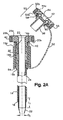
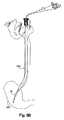
ここで図面を参照して、本発明の実施形態に従って構築されたオーバーチューブデバイスの斜視アセンブリ図が図1に示される。詳細には、内側チューブ10、外側チューブ12およびつながれたキャップ50が、別個の位置に示される。これらのチューブは、内視鏡を用いる手順の一部としてヒト被験体に挿管することにおける使用のためのオーバーチューブデバイスを形成する。図2Aは、図1のデバイスの拡大断面図であり、アセンブルされた位置にある内側チューブ10および外側チューブ12を示す。
Referring now to the drawings, a perspective assembly view of an overtube device constructed in accordance with an embodiment of the present invention is shown in FIG. Specifically, the
外側チューブ12は、細長いチューブ14、このチューブ14の遠位端上に配置されたテーパー状部分16、およびこのチューブ14の近位端上に配置された第1のハンドル18を含む。この細長いチューブ14は、印22を識別する長さを含み得る。示されるように、この印22は、外側チューブ上の一連の等しく間隔を置かれた長さのマーキングである。これらのマーキングは、医師がこの細長いチューブ14の初期挿入の間に深さをモニターすること、および複数の挿管の間にアセンブリの任意の移動をモニターすることを可能にする。示される外側チューブは50cmのチューブであるが、本発明は、任意の特定のチューブ長さに制限されないことは、当業者に明瞭である。この細長いチューブ14はまた、チューブの一部分に周縁方向に間隔を置かれたコイルを含み得る。これらコイルは、挿入の間にこのチューブに強度を付加する。
The
第1のハンドル18は、ベース18b、近位端19aおよび遠位端19bを有する。ベース18bは、ハードプラスチックから構築され、そしてオペレーターがハンドルを握ることを補助するために発泡体材料20で被覆され得る。図1および図2Aに見られるように、この第1のハンドル18の近位端は、ねじ山のある開口部23である。
The
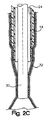
内側チューブ10は、細長いチューブ24、この細長いチューブ24の遠位端上に配置されたテーパー状のカフ26、および第2のハンドル28を含む。この細長いチューブ24は、例えば、押し出しポリ塩化ビニルのような、任意の適切なポリマーから構築され得る。示されるように、この細長いチューブ24は、任意の種類の内部コイルまたはスプリングなくして示される。コイルの欠如はコストを減少し、そして内視鏡のためのクリアランス(隙間)空間を増加する。しかし、コイルは、本発明の実施において、内側チューブに強度を付加するために用いられ得る。示される内側チューブは透明であるが、艶消しであってもよい。このような処理は、内側チューブと外側チューブとの間、および内側チューブと内視鏡との間の摩擦を減少する。
ここで図2Bを参照して、図2Aのアセンブリの拡大断面図が、内側チューブ24を通って同軸に挿入される内視鏡30をともなって示される。この細長いチューブ24は、示された従来の内視鏡の外径D2より大きい内径D1を有する。その結果、隙間が、内側チューブ24と内視鏡30との間に、内側チューブのほぼ全長に沿って存在する。この隙間は、内側チューブ24内の内視鏡30の挿入の間の摩擦を減少する。
Referring now to FIG. 2B, an enlarged cross-sectional view of the assembly of FIG. 2A is shown with an
上記外側チューブと内側チューブとの間のサイズの関係もまた、摩擦を減少するように設計される。内側チューブの外径は、外側チューブの内径よりも小さい。その結果、図2Aに示されるように、内側チューブが外側チューブ内に同軸に挿入されるとき、内側チューブと外側チューブとの間に、内側チューブの長さに沿って隙間が存在する。この隙間は、内側チューブ10の医師の外側チューブ12内の初期挿入を容易にする。
The size relationship between the outer tube and the inner tube is also designed to reduce friction. The outer diameter of the inner tube is smaller than the inner diameter of the outer tube. As a result, as shown in FIG. 2A, when the inner tube is inserted coaxially into the outer tube, there is a gap along the length of the inner tube between the inner tube and the outer tube. This gap facilitates initial insertion of the
述べられるように、図1に示される内側チューブ10は、カフを含む。このテーパー状のカフ26は、結合形成または特定のその他の適切な公知の方法によって細長いチューブ24の遠位端上に固定される。図1および2aに示されるように、カフ26は、長さL1だけ細長いチューブ24と重複する。このカフ26は、内側カフ直径D3を規定するテーパー状部分32を有する。この内径は、このカフ26が、それを通って挿入される内視鏡30の外面の周りのシールを形成する。このテーパー状のカフ26は、例えば、浸漬成形プロセスまたは射出成形からのような、種々の方法から構築され得る。さらに、この細長いチューブ24およびカフ26は、一体の片として構築され得る。
As mentioned, the
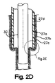
図3は、図2Bに示されるアセンブリで挿管されたヒト患者を示す概略図である。内側チューブ10の遠位端が外側チューブ12の遠位端13を超えて挿入されるとき、この内側チューブ遠位端と外側チューブ遠位端がシールを形成する。図2Aおよび2Bに示されるアセンブルされた位置では、外側チューブの遠位端および内側チューブの遠位端はシールされ、挿入の間の食道組織の任意の損傷およびつまむことを防ぐ。図2Cは、図2Bの底部分の拡大された断面図である。食道205の組織の層に対する外側チューブ14、内側チューブ24および内視鏡30の位置が示される。複数の層、すなわち、粘膜27a、粘膜下組織27b、および筋層27cがデバイスのいずれかの側に示される。組織をつまむこと、または裂けは生じていない。
FIG. 3 is a schematic diagram illustrating a human patient intubated with the assembly shown in FIG. 2B. When the distal end of the
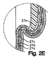
ここで、図2Dを参照して、先行技術デバイスの断面図が示される。詳細には、先行技術オーバーチューブ27dおよび内視鏡30の位置が、食道もの組織の層27a、27b、27cに関して示される。この設計では、これらの層は、内視鏡30とオーバーチューブ27dとの間の領域中で口に向かってもどってカールさせられる。この領域中の組織は、つままれる傾向にある。代表的な結果は、図2eに示され、これは、図2Dの示される円領域の断面図である。粘膜27aを通り、そして粘膜下組織27b層中に延びる「V形状」の裂け27eが示される。例えば、3つすべての層を通る完全な裂けのような、その他のせん断、裂けおよびつまみのパターンが、先行技術では公知である。
Now referring to FIG. 2D, a cross-sectional view of a prior art device is shown. Specifically, the position of the
述べたように、そして再び図2Aを参照して、内側チューブ10は、細長いチューブ24の遠位端に第2のハンドル28を含む。この第2のハンドル28は、ベース28b、近位端29aおよび遠位端29bを有する。このベース28bは、ハードプラスチックから構築され、そして、例えば、第2のハンドル28を第1のハンドル18に連結するようなとき、オペレーターがこのハンドル28を握ることを助けるために発泡体グリップ材料40で被覆され得る。
As mentioned, and referring again to FIG. 2A, the
図1に見られるように、第1のハンドル18の遠位端は、外部にねじ山をもつ部分42を含む。内側チューブ10の遠位端11が外側チューブ12の遠位端13を超えて挿入されるとき、この第1のハンドル18近位端19a中のねじ山のある部分23は、第2のハンドル28遠位端29b中のねじ山のある部分42に容易に連結され得る。従って、この第1のハンドル18は、第2のハンドル28の遠位側にある。
As can be seen in FIG. 1, the distal end of the
図2Aをなお参照して、シールキャップ50がテザー52によって外側チューブ12に連結されて示される。このキャップ50は、第1のハンドル18の遠位端19bに隣接する位置で連結される。プラスチックリング54がテザー52のいずれかの端部に配置される。このテザー52は、シール位置にないとき、ハンドル18の近傍内にキャップ50を保持する。
Still referring to FIG. 2A, a
このキャップ50は、ベース50b、近位端55aおよび遠位端55bを有する。ベース50bは、ハードプラスチックから構築され、そして使用の容易さのために発泡体材料56で被覆され得る。図2Aに見られるように、このベース50bは、第1のハンドル18の外側チューブ12の近位端19a中に直接挿入され得る。突出部58の近位端は、図4Aに示されるように、第1のハンドル18の近位端19a中のねじ山のある部分23への連結のために外側にねじ山のある部分60を含む。
The
示されるようなシールキャップは、中央アパーチャ64を有する可撓性シール62を含む。このシール62のアパーチャ64は、それを通って挿入される内視鏡の外面の周りにシールを形成するようなサイズである。外側チューブ12上に設置されるシールキャップ50は、内側チューブ10を除去して図5A中に示される。示されるように、シールがシール60と内視鏡30との間に形成される。この位置では、内視鏡30は、外側チューブの長さ内で側方に自由に移動する。シールは、内視鏡の側方のいずれかの方向への内視鏡の移動の間に内視鏡の周りで維持される。結果として、内視鏡とシールとの間には、通気はない。図5Bは、図5Aに示されるアセンブリで挿管されたヒト患者の概略図を示す。
The seal cap as shown includes a flexible seal 62 having a
キャップ50は、1つ以上のシールを含み得るか、または1つ以上のアパーチャを有するシールを含み得る。図12は、本発明の代替のキャップ65の斜視アセンブル図である。このキャップ65は、内視鏡30の挿入のための第1のアパーチャ64、および、例えば、スネア、ネット、または吸入デバイスのような第2の内視鏡器具70の挿入のための第2のアパーチャ68である、2つのアパーチャを有するシール66を含む。示されるように、シールが、シール66と内視鏡30との間、およびシール66と器具70との間に形成される。
The
図6は、本発明の別の実施形態の断面図である。示されるように、内視鏡30は、外側チューブ114を通って挿入される。テーパー状部分132を有するカフ126が外側チューブ114の遠位端上に接着される。このテーパー状のカフ126は、示されるように、それを通って挿入された内視鏡30の外面の周りにシールを形成する。ハンドル130は、この外側チューブ114の近位端に固定される。このデバイスは、テザー134によって外側チューブ114に連結されるキャップ132を含む。このキャップ132は、ハンドル130の近位端に取り外し可能に連結可能である。このキャップは、示されるようにそれを通って挿入される内視鏡30の外面の周りにシールを形成するように適合されたアパーチャ136を有する。
FIG. 6 is a cross-sectional view of another embodiment of the present invention. As shown,
図7Aは、本発明のなお別の実施形態の断面図である。細長い内側チューブ24が細長い外側チューブ14中に挿入されて示され、内視鏡30は、内側チューブを通って挿入される。外側チューブ14の遠位端には、保護フード140が、外側チューブに固定されて逆さの位置で示される。本発明の実施において、このフードは、胃腸管中の外来物体の捕獲で用いられる。詳細には、このフードは、この物体が除去されているとき、食道、気管および喉を-保護する。従って、このフード140は、十分な強度の任意の適切な引き裂き耐性のポリマーから構築され得る。非ラテックス材料が、アレルギーによって引き起こされる刺激または反応を防ぐために好ましい。
FIG. 7A is a cross-sectional view of yet another embodiment of the present invention. An elongated
フードを含む本発明の別の実施形態が、図7Bに示される。内視鏡30は、外側チューブ114を通って挿入されて示される。保護フード140は、外側チューブ114の遠位端に固定される。このフード140は、逆さの位置で示される。例示の目的のために、図7Bのデバイスを用いてカミソリの刃の除去が論議される。
Another embodiment of the invention including a hood is shown in FIG. 7B. The
図8は、図7Bのデバイスの断面図であり、前方方向にある保護フード140を示す。除去プロセスの開始時に、医師は、デバイスの遠位端を胃の中に挿入する。内視鏡30とテーパー状のカフ132との間にシールが形成される。その結果、初期挿入の間に食道組織のつまみ、または裂けは起こらない。
FIG. 8 is a cross-sectional view of the device of FIG. 7B showing the
胃の中では、デバイスを戻って引くことにより、図8に示される前方位置にフードを操作することが可能である。一旦、フードがこの前方位置にあると、内視鏡30は、フード中に延ばされ得る。スナア器具142が、内視鏡30の器具チャネル内に示される。
In the stomach, the hood can be operated to the forward position shown in FIG. 8 by pulling the device back. Once the hood is in this forward position, the
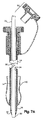
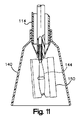
カミソリの刃150の物理的捕獲が図9〜11に示される。図9では、スネア器具142のループ144が、このカミソリの刃に向かって延ばされる。図10は、スネアループ144内のカミソリの刃150を示す。図11では、このスネアループは、退却され、そして保護フード144内に戻って折り畳まれて示される。全体の捕獲プロセスを通じ、内視鏡30と外側チューブ114の遠位端との間でシールが維持される。
The physical capture of the
本発明の実施形態の使用の方法が論議される。この方法は、内視鏡手順の一部としてヒト患者に挿管するためである。図1に示されるような内側チューブ10および外側チューブ12が選択される。この内側チューブ10は、図2Aに示されるように、外側チューブ12の全長を通じ、内側チューブ10の遠位端が、外側チューブ12の遠位端を超えて延びるように挿入される。この挿入ステップは、アセンブリの遠位端でチューブ10、12間にシールを形成する。
Methods of use of embodiments of the present invention are discussed. This method is for intubation into a human patient as part of an endoscopic procedure. An
次の方法ステップは、図2Bに示されるように、内側チューブ10内に内視鏡30を挿入することである。内視鏡が内側チューブ10内に挿入された後、次いで、シールが、連結、例えば、ねじのあるキャップ、スナップばめ連結、または差込みスタイル連結によって近位端に生成される。次いで、デバイスが、図3に示されるような所望の内部位置に送達される。この例では、デバイスは、食道205を通って胃200まで挿入されて示される。この方法は、任意の食道組織の層が、挿間の間の内側チューブと外側チューブ遠位端との間、または内側チューブテーパー状遠位端と内視鏡との間でつままれるのを防ぐことを含む。所望の挿入効果の例は、図2Cに示される。
The next method step is to insert an
次に、近位連結が解放され、そして内側チューブ10と内視鏡30が除去される。外側チューブ12はその場にとどまる。内側チューブ10が、効率的、迅速かつ協調様式で外側チューブ12から外される任意の連結構造が適切である。例示の構造は、スナップばめ連結および直角掛け連結を含む。
Next, the proximal connection is released and the
キャップは、次いで、外側チューブ12の近位端に連結される。キャップと外側チューブ12との間の例示のねじ連結が図4Aに示される。この連結がなされた後、デバイスは、図4Bに示されるようにその場に残る。
The cap is then connected to the proximal end of the
上記方法は、図5Aに示されるように、シールを形成するためにキャップ50中のアパーチャを通じて内視鏡30を挿入するステップを含む。図5Bでは、内視鏡30は、外側チューブ12の全長を通じて、外側チューブ遠位端を超えるまで挿入されて示される。この位置において、医師は、内視鏡手順の実質的部分を実施し得る。
The method includes inserting an
上記方法は、複数の挿管、すなわち、実質的手順の間の内視鏡の繰り返し除去および挿入を含み得る。繰り返し挿入は、特定の内視鏡手順のために必要であり得る。外側チュープ12は、食道の組織を保護するための全手順の間でその場にある。
The method may include multiple intubations, ie, repeated removal and insertion of the endoscope during a substantial procedure. Repeated insertion may be necessary for certain endoscopic procedures. The
本発明のいくつかの実施形態が示され、そして説明されたが、本発明は、開示される正確な構築に制限されと考慮されるべきではない。本発明の種々の適合、改変および使用が本発明が関連する当業者に生じ得る。添付の請求項の範囲または思想内に入るすべてのこのような適合、改変および使用を包含することが意図される。 While several embodiments of the present invention have been shown and described, the present invention should not be considered limited to the exact construction disclosed. Various adaptations, modifications and uses of the invention may occur to those skilled in the art to which the invention pertains. It is intended to embrace all such adaptations, modifications and uses that fall within the scope or spirit of the appended claims.
Claims (37)
a.外側チューブであって:
i.内径、近位端および遠位端を有する細長いチューブ;および
ii.該チューブの近位端上に配置されるハンドルであって、近位端および遠位端を有するハンドルを備える外側チューブ;
b.内側チューブであって:
i.外径、内径、近位端および遠位端を有する細長いチューブ;
ii.カフ内径およびカフ外径を有する該遠位端上に配置されるテーパー状のカフ;および
iii.該チューブの近位端上に配置されたハンドルであって、近位端および遠位端を有するハンドルを備え;
iv.ここで、該内側チューブのハンドルの遠位端が、該外側チューブのハンドルの近位端を係合するように適合されている、内側チューブ;および
c.該外側チューブのハンドルの近位端をシールして連結するように適合されたキャップ、を備え、
d.該内側チューブの外側直径が、該外側チューブの内径より小さく、該内側チューブが該外側チューブ内に同軸に挿入されるとき、該内側チューブの長さに沿って該内側チューブと該外側チューブとの間に隙間が存在し;
e.ここで、該外側チューブの遠位端および該内側チューブの遠位端がシールされる、オーバーチューブシステム。 An overtube system for use in intubating a human subject as part of a procedure using an endoscope having an outer diameter:
a. The outer tube:
i. An elongated tube having an inner diameter, a proximal end and a distal end; and ii. An outer tube comprising a handle disposed on a proximal end of the tube, the handle having a proximal end and a distal end;
b. The inner tube:
i. An elongated tube having an outer diameter, an inner diameter, a proximal end and a distal end;
ii. A tapered cuff disposed on the distal end having a cuff inner diameter and a cuff outer diameter; and iii. A handle disposed on a proximal end of the tube, the handle having a proximal end and a distal end;
iv. Wherein the distal end of the handle of the inner tube is adapted to engage the proximal end of the handle of the outer tube; and c. A cap adapted to seal and connect the proximal end of the handle of the outer tube;
d. When the outer diameter of the inner tube is smaller than the inner diameter of the outer tube and the inner tube is inserted coaxially into the outer tube, the inner tube and the outer tube are moved along the length of the inner tube. There is a gap between them;
e. Wherein the distal end of the outer tube and the distal end of the inner tube are sealed.
a.遠位端、近位端、および該近位端上に配置された第1のハンドルを有する細長いチューブを備える外側チューブ;および
b.遠位端、近位端、および該近位端上に配置された第2のハンドルを有する細長いチューブを備える内側チューブを備え;
c.アセンブルされた位置で、該内側チューブが該外側チューブの全長を通って延び、該内側チューブの遠位端が、該外側チューブの遠位端を超えて延び、そして該第1のハンドルが該第2のハンドルの遠位方向にある、デバイス。 An overtube device for use in intubating a human subject during an endoscopic procedure comprising:
a. An outer tube comprising an elongate tube having a distal end, a proximal end, and a first handle disposed on the proximal end; and b. An inner tube comprising an elongate tube having a distal end, a proximal end, and a second handle disposed on the proximal end;
c. In the assembled position, the inner tube extends through the entire length of the outer tube, the distal end of the inner tube extends beyond the distal end of the outer tube, and the first handle is the first handle. The device in the distal direction of the two handles.
a.遠位端、近位端および該近位端上に配置された第1のハンドルを有する外側チューブを選択する工程;
b.遠位端、近位端および該近位端上に配置された第2のハンドルを有する内側チューブを選択する工程;
c.該外側チューブの全長を通じて該内側チューブを、該内側チューブの遠位端が該外側チューブの遠位端を超えて延びるように挿入する工程;
d.該内側チューブおよび該外側チューブで該ヒト患者を挿管する工程;
e.該患者から該有為側チューブを除去する工程;
f.該第1のハンドルにキャップを連結する工程であって、該キャップがアパーチャを有する工程;および
g.シールを形成するように該アパーチャを通り、そして該外側チューブの全長を通って該外側チューブの遠位端を超えるまで該内視鏡を挿入する工程、を包含する、方法。 A method of intubating a human patient with an endoscope:
a. Selecting an outer tube having a distal end, a proximal end, and a first handle disposed on the proximal end;
b. Selecting an inner tube having a distal end, a proximal end, and a second handle disposed on the proximal end;
c. Inserting the inner tube through the entire length of the outer tube such that the distal end of the inner tube extends beyond the distal end of the outer tube;
d. Intubating the human patient with the inner tube and the outer tube;
e. Removing the significant tube from the patient;
f. Connecting a cap to the first handle, the cap having an aperture; and g. Inserting the endoscope through the aperture to form a seal and through the entire length of the outer tube and beyond the distal end of the outer tube.
a.遠位端、近位端、および該近位端上に配置された第1のハンドルを有する細長いチューブを備える外側チューブ;
b.遠位端、近位端、および該近位端上に配置された第2のハンドルを有する細長いチューブを備える内側チューブ;および
c.該第1のハンドルの近位端に取り外し可能に連結可能であるキャップであって、それを通って挿入される内視鏡の外面の周りにシールを形成するよう適合されたアパーチャを有するキャップを備え;そして
d.ここで、該内部チューブが、該外側チューブの全長を通り、該内側チューブの遠位端が、該外側チューブの遠位端を超えて延び、そして該第1のハンドルの外径が、該第2のハンドルの遠位方向にある、デバイス。 An overtube device for use in intubating a human subject during an endoscopic procedure comprising:
a. An outer tube comprising an elongate tube having a distal end, a proximal end, and a first handle disposed on the proximal end;
b. An inner tube comprising an elongate tube having a distal end, a proximal end, and a second handle disposed on the proximal end; and c. A cap having an aperture adapted to form a seal around an outer surface of an endoscope inserted therethrough that is removably connectable to a proximal end of the first handle. Preparing; and d. Wherein the inner tube passes through the entire length of the outer tube, the distal end of the inner tube extends beyond the distal end of the outer tube, and the outer diameter of the first handle is The device in the distal direction of the two handles.
a.遠位端、近位端、および該近位端上に配置された第1のハンドルを有する細長いチューブを備える外側チューブ;
b.該第1のハンドルの近位端に取り外し可能に連結可能であるキャップであって、それを通って挿入される内視鏡の外面の周りにシールを形成するよう適合されたアパーチャを有するキャップを備え;および
c.該外側チューブの遠位端で連結される逆転可能な保護フードを備える、デバイス。 An overtube device for use in intubating a human subject during an endoscopic procedure comprising:
a. An outer tube comprising an elongate tube having a distal end, a proximal end, and a first handle disposed on the proximal end;
b. A cap having an aperture adapted to form a seal around an outer surface of an endoscope inserted therethrough that is removably connectable to a proximal end of the first handle. Comprising; and c. A device comprising a reversible protective hood coupled at a distal end of the outer tube.
a.遠位端、近位端および該近位端上に配置された第1のハンドルを有する外側チューブを選択する工程;
b.遠位端、近位端および該近位端上に配置された第2のハンドルを有する内側チューブを選択する工程;
c.該外側チューブの全長を通じて該内側チューブを、該内側チューブの遠位端が該外側チューブの遠位端を超えて延びるように挿入する工程;
d.該内側チューブのテーパー状遠位端と該外側チューブ遠位端との間にシールを形成する工程;
e.該内側チューブおよび該外側チューブで該ヒト患者を挿管する工程;および
f.挿管の間に、該患者の食道の任意の粘膜層が、該内側チューブのテーパー状遠位端と該外側チューブの遠位端との間につままれることを防ぐ工程、を包含する、方法。 A method of intubating a human patient with an overtube device comprising:
a. Selecting an outer tube having a distal end, a proximal end, and a first handle disposed on the proximal end;
b. Selecting an inner tube having a distal end, a proximal end, and a second handle disposed on the proximal end;
c. Inserting the inner tube through the entire length of the outer tube such that the distal end of the inner tube extends beyond the distal end of the outer tube;
d. Forming a seal between the tapered distal end of the inner tube and the distal end of the outer tube;
e. Intubating the human patient with the inner tube and the outer tube; and f. Preventing any mucosal layer of the patient's esophagus from being pinched between the tapered distal end of the inner tube and the distal end of the outer tube during intubation.
a.遠位端、近位端、および該近位端上に配置された第1のハンドルを有する細長いチューブを備える外側チューブ;
b.該遠位端に固定されたテーパー状のカフ;および
c.該第1のハンドルの近位端に取り外し可能に連結可能であるキャップであって、それを通って挿入される内視鏡の外面の周りにシールを形成するよう適合されたアパーチャを有するキャップを備え;
d.ここで、該テーパー状のカフが、それを通じて挿入される内視鏡の外面の周りにシールを形成する、オーバーチューブシステム。 An overtube device for use in intubating a human subject during an endoscopic procedure comprising:
a. An outer tube comprising an elongate tube having a distal end, a proximal end, and a first handle disposed on the proximal end;
b. A tapered cuff secured to the distal end; and c. A cap having an aperture adapted to form a seal around an outer surface of an endoscope inserted therethrough that is removably connectable to a proximal end of the first handle. Preparation;
d. Wherein the tapered cuff forms a seal around the outer surface of the endoscope inserted therethrough.
Applications Claiming Priority (2)
| Application Number | Priority Date | Filing Date | Title |
|---|---|---|---|
| US57526004P | 2004-05-28 | 2004-05-28 | |
| PCT/US2005/018818 WO2005117684A2 (en) | 2004-05-28 | 2005-05-31 | Overtube assembly |
Publications (2)
| Publication Number | Publication Date |
|---|---|
| JP2008511341A true JP2008511341A (en) | 2008-04-17 |
| JP2008511341A5 JP2008511341A5 (en) | 2008-07-03 |
Family
ID=35463291
Family Applications (1)
| Application Number | Title | Priority Date | Filing Date |
|---|---|---|---|
| JP2007515410A Pending JP2008511341A (en) | 2004-05-28 | 2005-05-31 | Overtube assembly |
Country Status (4)
| Country | Link |
|---|---|
| US (1) | US9661989B2 (en) |
| EP (1) | EP1768540A4 (en) |
| JP (1) | JP2008511341A (en) |
| WO (1) | WO2005117684A2 (en) |
Cited By (7)
| Publication number | Priority date | Publication date | Assignee | Title |
|---|---|---|---|---|
| JP2014512202A (en) * | 2011-02-21 | 2014-05-22 | インターサージカル アクチェンゲゼルシャフト | Respiratory improvements |
| JP2015173918A (en) * | 2014-03-17 | 2015-10-05 | オリンパス株式会社 | tube body |
| JP2016503682A (en) * | 2012-12-24 | 2016-02-08 | ノバダック テクノロジーズ インコーポレイテッド | Intracavity introducer |
| US9877654B2 (en) | 2006-02-07 | 2018-01-30 | Novadaq Technologies Inc. | Near infrared imaging |
| US9968244B2 (en) | 2000-07-14 | 2018-05-15 | Novadaq Technologies ULC | Compact fluorescence endoscopy video system |
| US10182709B2 (en) | 2002-01-15 | 2019-01-22 | Novadaq Technologies ULC | Filter for use with imaging endoscopes |
| US10293122B2 (en) | 2016-03-17 | 2019-05-21 | Novadaq Technologies ULC | Endoluminal introducer with contamination avoidance |
Families Citing this family (15)
| Publication number | Priority date | Publication date | Assignee | Title |
|---|---|---|---|---|
| US20050165275A1 (en) * | 2004-01-22 | 2005-07-28 | Kenneth Von Felten | Inspection device insertion tube |
| US7500947B2 (en) | 2004-01-29 | 2009-03-10 | Cannonflow, Inc. | Atraumatic arthroscopic instrument sheath |
| US7435214B2 (en) * | 2004-01-29 | 2008-10-14 | Cannuflow, Inc. | Atraumatic arthroscopic instrument sheath |
| JP5042593B2 (en) * | 2006-11-02 | 2012-10-03 | オリンパスメディカルシステムズ株式会社 | Stent recovery device |
| WO2008014425A2 (en) * | 2006-07-26 | 2008-01-31 | Hansen Medical, Inc. | Systems for performing minimally invasive surgical operations |
| JP5171076B2 (en) * | 2007-03-14 | 2013-03-27 | 富士フイルム株式会社 | Endoscope device |
| US8287447B2 (en) * | 2007-08-29 | 2012-10-16 | Minos Medical | Outer tube for natural orifice surgery |
| US20090062614A1 (en) * | 2007-08-29 | 2009-03-05 | Minos Medical | Closures for outer tube for natural orifice surgery |
| WO2009119053A1 (en) * | 2008-03-24 | 2009-10-01 | 住友ベークライト株式会社 | De-aeration prevention valve unit for an overtube |
| US20110125097A1 (en) * | 2009-11-24 | 2011-05-26 | Shaw Thomas J | Catheter Introducer with Hub Seal and Removal Tab |
| US20130231533A1 (en) * | 2011-05-23 | 2013-09-05 | Stephanos Papademetriou | Medical applications of a miniature videoscope |
| GB201120736D0 (en) * | 2011-12-02 | 2012-01-11 | Surgical Innovations Ltd | Cannula top and system |
| DE102017002527A1 (en) * | 2017-03-16 | 2018-09-20 | Joimax Gmbh | Device for access to the interior of a body |
| CN108771559A (en) * | 2018-05-29 | 2018-11-09 | 成都维信电子科大新技术有限公司 | A kind of abdominal cavity puncture outfit |
| WO2023150055A1 (en) * | 2022-02-01 | 2023-08-10 | Endoquest Robotics, Inc. | Systems and method for trans-luminal introduction of a medical device |
Citations (11)
| Publication number | Priority date | Publication date | Assignee | Title |
|---|---|---|---|---|
| JPS5529338A (en) * | 1978-08-22 | 1980-03-01 | Masazumi Takada | Flexible body cavity inside insertion appliance |
| US4657020A (en) * | 1985-07-10 | 1987-04-14 | Jayco Pharmaceuticals | Method of using a foreign object protector hood |
| US4846153A (en) * | 1988-06-10 | 1989-07-11 | George Berci | Intubating video endoscope |
| US4913139A (en) * | 1989-02-09 | 1990-04-03 | Ballew Donald H | Method of translaryngeal retrograde tracheal intubation |
| JPH02139603U (en) * | 1989-04-25 | 1990-11-21 | ||
| JPH04263870A (en) * | 1990-10-03 | 1992-09-18 | Cook Inc | Medical apparatus and endermic arrange- ment thereof in body cavity |
| JPH0751221A (en) * | 1993-08-18 | 1995-02-28 | Sumitomo Bakelite Co Ltd | Guide tube |
| US5941815A (en) * | 1996-12-05 | 1999-08-24 | Helix Medical, Inc. | Sigmoid splint device for endoscopy |
| US6543446B1 (en) * | 1996-02-26 | 2003-04-08 | Evergreen Medical Incorporated | Method and apparatus for ventilation/oxygenation during guided insertion of an endotracheal tube |
| US6551282B1 (en) * | 1998-02-23 | 2003-04-22 | Tyco Healthcare Group Lp | Universal seal for use with endoscopic cannula |
| US6663646B1 (en) * | 2000-10-24 | 2003-12-16 | Tilak M. Shah | Isotropically expansible balloon articles useful in in vivo lumenal procedures, and method of making such balloon articles |
Family Cites Families (51)
| Publication number | Priority date | Publication date | Assignee | Title |
|---|---|---|---|---|
| US4580556A (en) * | 1984-04-13 | 1986-04-08 | Kondur Prabhakar R | Adaptor for endotracheal intubation |
| US5203320A (en) * | 1987-03-24 | 1993-04-20 | Augustine Medical, Inc. | Tracheal intubation guide |
| US4815450A (en) * | 1988-02-01 | 1989-03-28 | Patel Jayendra I | Endoscope having variable flexibility |
| DE3935256C1 (en) | 1989-10-23 | 1991-01-03 | Bauerfeind, Peter, Dr., 8264 Waldkraiburg, De | |
| US5037386A (en) | 1989-11-17 | 1991-08-06 | Minnesota Mining And Manufacturing Company | Pressure sensing scope cannula |
| DE4101472C2 (en) * | 1991-01-19 | 1995-07-13 | Winter & Ibe Olympus | Endoscope for transurethral resection |
| US5632761A (en) * | 1991-05-29 | 1997-05-27 | Origin Medsystems, Inc. | Inflatable devices for separating layers of tissue, and methods of using |
| US5279610A (en) * | 1992-11-06 | 1994-01-18 | Cook Incorporated | Oroesophageal, instrument introducer assembly and method of use |
| US5342315A (en) | 1993-04-12 | 1994-08-30 | Ethicon, Inc. | Trocar seal/protector assemblies |
| US5486154A (en) * | 1993-06-08 | 1996-01-23 | Kelleher; Brian S. | Endoscope |
| US5657963A (en) | 1993-06-16 | 1997-08-19 | United States Surgical Corporation | Seal assembly for accommodating introduction of surgical instruments |
| US5397335A (en) | 1993-07-13 | 1995-03-14 | Origin Medsystems, Inc. | Trocar assembly with improved adapter seals |
| US5643174A (en) * | 1993-08-18 | 1997-07-01 | Sumitomo Bakelite Company Limited | Endoscopic guide tube with embedded coil spring |
| US5392766A (en) * | 1993-10-06 | 1995-02-28 | Innerdyne Medical, Inc. | System and method for cleaning viewing scope lenses |
| AU701424B2 (en) | 1994-10-24 | 1999-01-28 | Smith & Nephew, Inc. | Hollow surgical cutter with apertured flutes |
| US6689086B1 (en) | 1994-10-27 | 2004-02-10 | Advanced Cardiovascular Systems, Inc. | Method of using a catheter for delivery of ultrasonic energy and medicament |
| US5964740A (en) * | 1996-07-09 | 1999-10-12 | Asahi Kogaku Kogyo Kabushiki Kaisha | Treatment accessory for an endoscope |
| US5628732A (en) | 1996-01-19 | 1997-05-13 | Ethicon Endo-Surgery, Inc. | Trocar with improved universal seal |
| JP3225835B2 (en) * | 1996-03-14 | 2001-11-05 | 富士写真光機株式会社 | Endoscope treatment instrument fixing mechanism |
| SE9601974L (en) * | 1996-05-23 | 1997-10-13 | Elekta Ab | Device for injecting a substance into a body, especially human or animal |
| US6827710B1 (en) | 1996-11-26 | 2004-12-07 | Edwards Lifesciences Corporation | Multiple lumen access device |
| DE19743431B4 (en) | 1997-10-01 | 2011-02-17 | Karl Storz Gmbh & Co. Kg | Endoscope with composite window |
| DE19713275A1 (en) | 1997-03-29 | 1998-10-01 | Storz Karl Gmbh & Co | Endoscope with length compensation under thermal stress |
| CA2291838C (en) | 1997-05-28 | 2006-07-18 | David C. Racenet | Trocar seal system |
| US5954636A (en) * | 1997-07-15 | 1999-09-21 | Schwartz; Roy E. | Pediatric endotracheal tube with bronchial blocker and method for selectively blocking respiratory airflow to a pediatric patient's lung |
| US6079409A (en) * | 1997-07-25 | 2000-06-27 | Brain; Archibald Ian Jeremy | Intubating laryngeal mask |
| WO1999013934A1 (en) | 1997-09-12 | 1999-03-25 | Nippon Zeon Co., Ltd. | Balloon catheter |
| US5846182A (en) * | 1997-09-15 | 1998-12-08 | Olympus America, Inc. | Esophageal overtube for smoke evacuation |
| US6197002B1 (en) | 1997-12-10 | 2001-03-06 | Phillips Plastics Corporation | Laparoscopic tool and method |
| JP3321075B2 (en) | 1998-03-17 | 2002-09-03 | 旭光学工業株式会社 | Endoscope forceps stopper |
| US6322538B1 (en) | 1999-02-18 | 2001-11-27 | Scimed Life Systems, Inc. | Gastro-intestinal tube placement device |
| US6364867B2 (en) * | 1999-07-01 | 2002-04-02 | Catheter Innovations, Inc. | Anti-clotting methods and apparatus for indwelling catheter tubes |
| US6615835B1 (en) * | 1999-09-20 | 2003-09-09 | Ballard Medical Products | Flexible multiple port adaptor |
| US6761171B2 (en) * | 1999-09-27 | 2004-07-13 | Andrew J. Toti | Endotracheal tube with tip directional control and position preserving mechanism |
| US6508757B1 (en) * | 1999-10-25 | 2003-01-21 | Paul Huan Song | Attachment to flexible bronchoscope, slotted tubular stylet for endotracheal intubation |
| US6470888B1 (en) * | 1999-11-08 | 2002-10-29 | Freya, Llc | System for in vivo sterilization of a respiratory circuit |
| US7131959B2 (en) * | 2003-01-23 | 2006-11-07 | Integrated Vascular Interventional Technologies, L.C., (“IVIT LC”) | Apparatus and methods for occluding an access tube anastomosed to sidewall of an anatomical vessel |
| US6361540B1 (en) | 2000-04-06 | 2002-03-26 | Michael W. L. Gauderer | Apparatus for removal of esophageal coins and similarly shaped objects |
| US6638289B1 (en) | 2000-10-16 | 2003-10-28 | Stryker Corporation | Elongated endoscopic cutting accessories |
| US6585639B1 (en) * | 2000-10-27 | 2003-07-01 | Pulmonx | Sheath and method for reconfiguring lung viewing scope |
| US6663614B1 (en) | 2000-11-06 | 2003-12-16 | Advanced Cardiovascular Systems, Inc. | Catheter shaft having variable thickness layers and method of making |
| EP1443851A1 (en) * | 2001-10-18 | 2004-08-11 | Atropos Limited | A device to aid advancement of a colonoscope |
| DE50100883D1 (en) | 2001-11-27 | 2003-12-04 | Storz Karl Gmbh & Co | Seal for an endoscope |
| JP4263870B2 (en) | 2002-03-11 | 2009-05-13 | アルプス電気株式会社 | Haptic controller |
| JP3831683B2 (en) | 2002-05-16 | 2006-10-11 | ペンタックス株式会社 | Bending prevention of flexible tube insertion part of endoscope with outer sheath |
| US7396332B2 (en) | 2002-06-10 | 2008-07-08 | Scimed Life Systems, Inc. | Transducer with multiple resonant frequencies for an imaging catheter |
| US7575571B2 (en) | 2002-10-29 | 2009-08-18 | Medtronic, Inc. | Indexing cell delivery catheter |
| EP1578281A2 (en) * | 2002-11-25 | 2005-09-28 | Boston Scientific Limited | Injection device for treating mammalian body |
| US6978784B2 (en) * | 2003-12-11 | 2005-12-27 | The Research Foundation State University Of New York | Atraumatic endotracheal tube introducer and atraumatic intubation methods |
| US6962438B2 (en) * | 2004-02-10 | 2005-11-08 | Kuan-Yu Chu | Temperature sensor temperature sensing tube |
| AU2005260071B2 (en) * | 2004-06-29 | 2011-06-30 | Applied Medical Resources Corporation | Insufflating optical surgical instrument |
-
2005
- 2005-05-31 JP JP2007515410A patent/JP2008511341A/en active Pending
- 2005-05-31 EP EP05754866A patent/EP1768540A4/en not_active Withdrawn
- 2005-05-31 US US11/141,450 patent/US9661989B2/en active Active
- 2005-05-31 WO PCT/US2005/018818 patent/WO2005117684A2/en active Application Filing
Patent Citations (11)
| Publication number | Priority date | Publication date | Assignee | Title |
|---|---|---|---|---|
| JPS5529338A (en) * | 1978-08-22 | 1980-03-01 | Masazumi Takada | Flexible body cavity inside insertion appliance |
| US4657020A (en) * | 1985-07-10 | 1987-04-14 | Jayco Pharmaceuticals | Method of using a foreign object protector hood |
| US4846153A (en) * | 1988-06-10 | 1989-07-11 | George Berci | Intubating video endoscope |
| US4913139A (en) * | 1989-02-09 | 1990-04-03 | Ballew Donald H | Method of translaryngeal retrograde tracheal intubation |
| JPH02139603U (en) * | 1989-04-25 | 1990-11-21 | ||
| JPH04263870A (en) * | 1990-10-03 | 1992-09-18 | Cook Inc | Medical apparatus and endermic arrange- ment thereof in body cavity |
| JPH0751221A (en) * | 1993-08-18 | 1995-02-28 | Sumitomo Bakelite Co Ltd | Guide tube |
| US6543446B1 (en) * | 1996-02-26 | 2003-04-08 | Evergreen Medical Incorporated | Method and apparatus for ventilation/oxygenation during guided insertion of an endotracheal tube |
| US5941815A (en) * | 1996-12-05 | 1999-08-24 | Helix Medical, Inc. | Sigmoid splint device for endoscopy |
| US6551282B1 (en) * | 1998-02-23 | 2003-04-22 | Tyco Healthcare Group Lp | Universal seal for use with endoscopic cannula |
| US6663646B1 (en) * | 2000-10-24 | 2003-12-16 | Tilak M. Shah | Isotropically expansible balloon articles useful in in vivo lumenal procedures, and method of making such balloon articles |
Cited By (8)
| Publication number | Priority date | Publication date | Assignee | Title |
|---|---|---|---|---|
| US9968244B2 (en) | 2000-07-14 | 2018-05-15 | Novadaq Technologies ULC | Compact fluorescence endoscopy video system |
| US10182709B2 (en) | 2002-01-15 | 2019-01-22 | Novadaq Technologies ULC | Filter for use with imaging endoscopes |
| US9877654B2 (en) | 2006-02-07 | 2018-01-30 | Novadaq Technologies Inc. | Near infrared imaging |
| JP2014512202A (en) * | 2011-02-21 | 2014-05-22 | インターサージカル アクチェンゲゼルシャフト | Respiratory improvements |
| US10207073B2 (en) | 2011-02-21 | 2019-02-19 | Intersurgical Ag | Respiratory apparatus |
| JP2016503682A (en) * | 2012-12-24 | 2016-02-08 | ノバダック テクノロジーズ インコーポレイテッド | Intracavity introducer |
| JP2015173918A (en) * | 2014-03-17 | 2015-10-05 | オリンパス株式会社 | tube body |
| US10293122B2 (en) | 2016-03-17 | 2019-05-21 | Novadaq Technologies ULC | Endoluminal introducer with contamination avoidance |
Also Published As
| Publication number | Publication date |
|---|---|
| EP1768540A2 (en) | 2007-04-04 |
| US20050267331A1 (en) | 2005-12-01 |
| US9661989B2 (en) | 2017-05-30 |
| WO2005117684A3 (en) | 2009-04-02 |
| EP1768540A4 (en) | 2010-03-24 |
| WO2005117684A2 (en) | 2005-12-15 |
Similar Documents
| Publication | Publication Date | Title |
|---|---|---|
| JP2008511341A (en) | Overtube assembly | |
| JP7133111B2 (en) | Endotracheal tube insertion device | |
| JP6937183B2 (en) | Endoscopy equipment | |
| JP7133110B2 (en) | Endotracheal tube insertion device | |
| JP6759320B2 (en) | Artificial airway device | |
| US8465419B2 (en) | Endoscope insertion unit, endoscope and endoscope system | |
| US20130324795A1 (en) | Three-dimensional retractor | |
| JP2008511341A5 (en) | ||
| JP2017508519A (en) | System and method for facilitating intubation | |
| JP2019141608A (en) | Endoscopy device | |
| JP2021524359A (en) | Tracheal cannula insertion device | |
| JP5469115B2 (en) | Double overtube | |
| US9345435B1 (en) | Esophageal introducer | |
| JP3129543U (en) | Overtube | |
| CN110650668B (en) | Instrument for accessing and visualizing a hollow organ | |
| JP7412425B2 (en) | Catheter and tube introducer | |
| JP2021529616A (en) | connector | |
| JP2007307001A (en) | Endoscopic submucosal dissection auxiliary device | |
| US20090287056A1 (en) | Device to facilitate suctioning of fluid during gastrointestinal endoscopy | |
| JP2011062429A (en) | Guide implement for introducing surgical instrument or the like into body | |
| JP2010000246A (en) | Colonoscope |
Legal Events
| Date | Code | Title | Description |
|---|---|---|---|
| A521 | Written amendment |
Free format text: JAPANESE INTERMEDIATE CODE: A523 Effective date: 20080513 |
|
| A621 | Written request for application examination |
Free format text: JAPANESE INTERMEDIATE CODE: A621 Effective date: 20080513 |
|
| A131 | Notification of reasons for refusal |
Free format text: JAPANESE INTERMEDIATE CODE: A131 Effective date: 20101130 |
|
| A601 | Written request for extension of time |
Free format text: JAPANESE INTERMEDIATE CODE: A601 Effective date: 20110218 |
|
| A602 | Written permission of extension of time |
Free format text: JAPANESE INTERMEDIATE CODE: A602 Effective date: 20110225 |
|
| A02 | Decision of refusal |
Free format text: JAPANESE INTERMEDIATE CODE: A02 Effective date: 20110720 Free format text: JAPANESE INTERMEDIATE CODE: A02 Effective date: 20110720 |