JP2008510147A - System and method for calibration of distribution devices - Google Patents
System and method for calibration of distribution devices Download PDFInfo
- Publication number
- JP2008510147A JP2008510147A JP2007525827A JP2007525827A JP2008510147A JP 2008510147 A JP2008510147 A JP 2008510147A JP 2007525827 A JP2007525827 A JP 2007525827A JP 2007525827 A JP2007525827 A JP 2007525827A JP 2008510147 A JP2008510147 A JP 2008510147A
- Authority
- JP
- Japan
- Prior art keywords
- flow
- coefficient
- viscosity
- test
- corrected
- Prior art date
- Legal status (The legal status is an assumption and is not a legal conclusion. Google has not performed a legal analysis and makes no representation as to the accuracy of the status listed.)
- Withdrawn
Links
Images


Classifications
-
- G—PHYSICS
- G01—MEASURING; TESTING
- G01F—MEASURING VOLUME, VOLUME FLOW, MASS FLOW OR LIQUID LEVEL; METERING BY VOLUME
- G01F25/00—Testing or calibration of apparatus for measuring volume, volume flow or liquid level or for metering by volume
-
- G—PHYSICS
- G01—MEASURING; TESTING
- G01F—MEASURING VOLUME, VOLUME FLOW, MASS FLOW OR LIQUID LEVEL; METERING BY VOLUME
- G01F1/00—Measuring the volume flow or mass flow of fluid or fluent solid material wherein the fluid passes through a meter in a continuous flow
- G01F1/05—Measuring the volume flow or mass flow of fluid or fluent solid material wherein the fluid passes through a meter in a continuous flow by using mechanical effects
- G01F1/34—Measuring the volume flow or mass flow of fluid or fluent solid material wherein the fluid passes through a meter in a continuous flow by using mechanical effects by measuring pressure or differential pressure
-
- G—PHYSICS
- G01—MEASURING; TESTING
- G01F—MEASURING VOLUME, VOLUME FLOW, MASS FLOW OR LIQUID LEVEL; METERING BY VOLUME
- G01F25/00—Testing or calibration of apparatus for measuring volume, volume flow or liquid level or for metering by volume
- G01F25/10—Testing or calibration of apparatus for measuring volume, volume flow or liquid level or for metering by volume of flowmeters
-
- G—PHYSICS
- G05—CONTROLLING; REGULATING
- G05B—CONTROL OR REGULATING SYSTEMS IN GENERAL; FUNCTIONAL ELEMENTS OF SUCH SYSTEMS; MONITORING OR TESTING ARRANGEMENTS FOR SUCH SYSTEMS OR ELEMENTS
- G05B13/00—Adaptive control systems, i.e. systems automatically adjusting themselves to have a performance which is optimum according to some preassigned criterion
- G05B13/02—Adaptive control systems, i.e. systems automatically adjusting themselves to have a performance which is optimum according to some preassigned criterion electric
- G05B13/0205—Adaptive control systems, i.e. systems automatically adjusting themselves to have a performance which is optimum according to some preassigned criterion electric not using a model or a simulator of the controlled system
- G05B13/024—Adaptive control systems, i.e. systems automatically adjusting themselves to have a performance which is optimum according to some preassigned criterion electric not using a model or a simulator of the controlled system in which a parameter or coefficient is automatically adjusted to optimise the performance
Landscapes
- Physics & Mathematics (AREA)
- General Physics & Mathematics (AREA)
- Fluid Mechanics (AREA)
- Engineering & Computer Science (AREA)
- Software Systems (AREA)
- Medical Informatics (AREA)
- Health & Medical Sciences (AREA)
- Evolutionary Computation (AREA)
- Computer Vision & Pattern Recognition (AREA)
- Automation & Control Theory (AREA)
- Artificial Intelligence (AREA)
- Flow Control (AREA)
- Measuring Volume Flow (AREA)
- Details Of Flowmeters (AREA)
- Monitoring And Testing Of Nuclear Reactors (AREA)
Abstract
本発明の実施形態は流通装置(30)の高速較正のためのシステム(200)と方法を提供する。流通装置には製造者または第三者より較正流れ曲線(例えば、n次多項式で表される)が与えられる。較正曲線は、プロセス流体や1つまたは複数の補正因子を使用して流通装置が実際にインストールされているシステムに対して調整できる。補正因子は簡単な実験的テストまたはプロセス流体の流体特性に基づく流れ曲線に対して決定され得る。補正された流れ曲線はその次に、将来の流れ制御に使えるよう流通装置に保存される。Embodiments of the present invention provide a system (200) and method for fast calibration of a flow device (30). The distribution device is provided with a calibration flow curve (eg, expressed by an nth order polynomial) from the manufacturer or a third party. The calibration curve can be adjusted for the system in which the flow device is actually installed using the process fluid and one or more correction factors. The correction factor can be determined for simple experimental tests or flow curves based on the fluid properties of the process fluid. The corrected flow curve is then stored in the distribution device for use in future flow control.
Description
本願は、タイトルが「System and Method for Calibration of a Flow Device」のLavardiereらによる米国仮特許出願第60/601,424号(2004年8月13日出願)の利益および優先権を、米国特許法119(e)の下、主張する。 This application claims the benefit and priority of US Provisional Patent Application No. 60 / 601,424 (filed Aug. 13, 2004) by Lavardiere et al., Entitled “System and Method for Calibration of a Flow Device”. Claims under 119 (e).
本発明は流通装置の較正、そして特に、質量流量計と質量流量制御器の高速較正に関する。 The present invention relates to flow device calibration, and in particular to high speed calibration of mass flow meters and mass flow controllers.
流量制御器は流体や気体の流量を制御するために様々な産業で使われている。流量制御器に依存度が高い産業の一つは半導体製造業である。これは、半導体の製造には流通室に供給される気体や流体の正確な制御を必要とするからである。現在多くの流量制御器は、差圧を基準として流量を制御している。これら流量制御器は半導体製造ツールまたはその他のシステムより設定点を受け、流体流路内で制限を加えるもの全てで差圧を測定し、設定点と差圧の差に基づいて弁を開閉する制御アルゴリズムを実行する。 Flow controllers are used in various industries to control fluid and gas flow rates. One industry that is highly dependent on flow controllers is the semiconductor manufacturing industry. This is because the manufacture of semiconductors requires precise control of the gas and fluid supplied to the distribution chamber. Currently, many flow controllers control the flow rate based on the differential pressure. These flow controllers receive set points from semiconductor manufacturing tools or other systems, measure differential pressure across all restrictions in the fluid flow path, and control to open and close valves based on the difference between the set point and differential pressure Run the algorithm.
通常、流量制御器は質量、または体積流量に関して設定点を受ける。質量または体積流量は次に、較正曲線に基づいて圧力差に変換される。したがって流量制御器は、プロセス流体や流量制御器が作動する動作条件に対して記憶された較正曲線を有さなくてはならない。様々な流体や様々な動作条件の下での使用に適した流量制御器のために、流量制御器製造業者は通常、流量制御器に数多くの較正曲線を提供するか、またはプロセス流体や流量制御器が作動する条件に対して個別に流量制御器を較正しなくてはならない。これは多大な時間を必要とし、非能率的な作業となり得る。したがって、流量制御器のより迅速なシステムと方法に対するニーズが存在する。 Typically, the flow controller receives a set point for mass or volume flow. The mass or volume flow is then converted to a pressure difference based on the calibration curve. Accordingly, the flow controller must have a stored calibration curve for the process fluid and the operating conditions under which the flow controller operates. For flow controllers suitable for use under different fluids and different operating conditions, flow controller manufacturers typically provide numerous calibration curves for the flow controller or process fluid and flow control. The flow controller must be individually calibrated for the conditions under which the device operates. This is time consuming and can be an inefficient task. Accordingly, there is a need for faster systems and methods for flow controllers.
本発明の実施形態は、流通装置を較正するための従来技術のシステムと方法の欠点を解消するか、または少なくとも実質的に改善する、流通装置の高速較正のためのシステムと方法を提供する。 Embodiments of the present invention provide systems and methods for fast calibration of distribution devices that eliminate or at least substantially improve the shortcomings of prior art systems and methods for calibrating distribution devices.
流通装置には製造者、または第三者より較正流れ曲線(例えば、n次多項式で表される)が与えられ得る。較正曲線は、プロセス流体や1つまたはそれ以上の補正因子を使用して流通装置が実際にインストールされているシステムに対して調整できる。補正因子は簡単な実験的テスト、またはプロセス流体の流体特性に基づく流れ曲線に対して決定され得る。補正済みの流れ曲線はその次に、将来の流量制御に使えるよう流通装置に保存される。 The flow device may be provided with a calibration flow curve (eg, expressed by an nth order polynomial) from the manufacturer or a third party. The calibration curve can be adjusted for the system where the flow device is actually installed using the process fluid and one or more correction factors. The correction factor can be determined for a simple experimental test or a flow curve based on the fluid properties of the process fluid. The corrected flow curve is then stored in the distribution device for use in future flow control.
本発明の一実施形態は、流体の流量を示す変数が試験値を有するように、流通装置を介して流体の流れを作り出すことを含む流通装置を較正する方法を含む。これは例えば、圧力差、時間差、特定のセンサーにおける圧力、または流体の流量を示す他の因子が、単一の試験値、または複数の試験値、または一セットの試験値を有することができるように、流れを作り出すことを含み得る。例えば、試験値は期待極大値の半分であり得る。この方法は更に、試験期間の間の流体の実験的流量を決定することと、流量変数に対する計算値を決定するために較正曲線を実験的流量に適用することとを含む。補正因子はその試験値と計算値とに基づいて決定され得る。 One embodiment of the present invention includes a method of calibrating a flow device that includes creating a fluid flow through the flow device such that a variable indicative of fluid flow rate has a test value. This can be, for example, that a pressure difference, time difference, pressure at a particular sensor, or other factor indicating fluid flow rate can have a single test value, or multiple test values, or a set of test values. Can include creating a flow. For example, the test value can be half the expected maximum. The method further includes determining an experimental flow rate of the fluid during the test period and applying a calibration curve to the experimental flow rate to determine a calculated value for the flow variable. The correction factor can be determined based on the test value and the calculated value.
他の実施形態は、コンピュータ可読媒体に記憶された一セットのコンピュータ命令を含むコンピュータプログラム製品を含み得る。この一セットの命令は、流量を示す一つ以上の変数の一つの試験値または一セットの試験値を決定することと、一つまたは複数の実験的流量や較正曲線に対応しているn次多項式に基づく流量を示す変数に対する一つまたは複数の計算値を決定することと、計算値や流量を示す変数に対する試験値に基づく一つまたは複数の補正因子を決定することとを実行可能な命令を含み得る。コンピュータ命令は流通装置の制御器および/または、流通装置と通信している較正コンピュータあるいはその他のコンピュータデバイスにより実行され得ることに留意されたい。 Other embodiments may include a computer program product that includes a set of computer instructions stored on a computer-readable medium. This set of instructions determines one test value or set of test values for one or more variables indicative of flow rate, and an nth order corresponding to one or more experimental flow rates or calibration curves. Instructions capable of determining one or more calculated values for a variable based on a polynomial and determining one or more correction factors based on test values for the calculated or flow variable. Can be included. Note that the computer instructions may be executed by a controller of the distribution device and / or a calibration computer or other computer device in communication with the distribution device.
本発明の更に他の実施形態は、流路と、流路内の流量制限上流の上流圧力センサーと、流路内の流量制限下流の下流圧力センサーと、上流および下流センサーから圧測定を受けるために上流圧力センサーおよび下流圧力センサーに連結されている制御器とを備えている流通装置を含む。その制御は、上流圧力センサーと下流圧力センサーとの間の一つまたは複数の試験圧力差を生み出すように流通装置を通して流体の流れを作り出すために一つまたは複数の試験期間中に弁を開き、実験的流量や較正流れ曲線に対応したn次多項式に基づいた1つまたは複数の計算された圧力差を決定し、計算された圧力差と試験圧力差に基づいた一つまたは複数の補正因子を生み出すように構成されている。制御器はまた、特定の補正因子の精度を向上させるか、または幾つかの補正因子を生み出すために、同じ設定点、または複数の設定点で一セットの試験圧力差を生み出すために幾つかの試験期間に制御器を開くよう構成され得る。 Yet another embodiment of the invention is for receiving pressure measurements from a flow path, an upstream pressure sensor upstream of a flow restriction in the flow path, a downstream pressure sensor downstream of the flow restriction in the flow path, and upstream and downstream sensors. And a controller connected to the upstream pressure sensor and the downstream pressure sensor. The control opens a valve during one or more test periods to create a fluid flow through the flow device to create one or more test pressure differences between the upstream and downstream pressure sensors, Determine one or more calculated pressure differences based on an nth order polynomial corresponding to the experimental flow rate or calibration flow curve and determine one or more correction factors based on the calculated pressure difference and the test pressure difference. It is configured to produce. The controller may also create several sets of test pressure differences at the same set point, or multiple set points, to improve the accuracy of a particular correction factor or to generate several correction factors. It may be configured to open the controller during the test period.
本発明の他の実施形態は、較正流体に対する較正曲線に対応しているn次多項式に対する一セットの係数を読み込むことと、プロセス流体に対する補正されたn次多項式を生み出すためにプロセス流体の粘性に基づいて一セットの係数の係数を補正することと、記憶域に補正された係数を記憶することとを含む、流通装置の較正方法を含む。 Another embodiment of the present invention reads a set of coefficients for an nth order polynomial corresponding to a calibration curve for a calibration fluid and adjusts the viscosity of the process fluid to produce a corrected nth order polynomial for the process fluid. A method for calibrating a distribution device is included that includes correcting a coefficient of a set of coefficients based on and storing the corrected coefficient in a storage area.
本発明の他の実施形態は、コンピュータ可読媒体に記憶されている一セットのコンピュータ命令を含む、流通装置を較正するためのコンピュータプログラム製品を含む。その一セットの命令は、較正曲線に対応しているn次多項式に対する一セットの係数を読み込み、一セットの粘性相関変数を読み込み、プロセス流体の粘性を示す入力を受信し、一セットの粘性相関変数に基づいて一セットの係数を補正し、補正された一セットの係数を記憶するようにプロセッサによって実行可能な命令を含む。 Another embodiment of the invention includes a computer program product for calibrating a distribution device that includes a set of computer instructions stored on a computer readable medium. The set of instructions reads a set of coefficients for an nth order polynomial corresponding to the calibration curve, reads a set of viscosity correlation variables, receives an input indicating the viscosity of the process fluid, and sets a viscosity correlation Instructions executable by the processor to correct the set of coefficients based on the variable and to store the corrected set of coefficients are included.
本発明の更に他の実施形態は、較正プログラムを記憶するコンピュータ可読媒体と較正プログラムにアクセスし較正プログラムを実行するプロセッサとを含む制御器を有する流通装置を含む。制御器は、較正流体に対する較正曲線に対応するn次多項式に対する一セットの係数を読み込み、プロセス流体に対する補正されたn次多項式に対する一セットの補正された係数を生み出すためにプロセス流体の粘性に基づいて一セットの係数の係数を補正し、記憶域に補正された係数を記憶するように動作可能である。 Yet another embodiment of the present invention includes a distribution device having a controller that includes a computer readable medium that stores a calibration program and a processor that accesses the calibration program and executes the calibration program. The controller reads a set of coefficients for the nth order polynomial corresponding to the calibration curve for the calibration fluid and based on the viscosity of the process fluid to produce a set of corrected coefficients for the corrected nth order polynomial for the process fluid. And correcting the coefficients of the set of coefficients and storing the corrected coefficients in the storage area.
本発明の他の実施形態は、流体の流量を示す変数が一セットの試験値を有するように流通装置を通して流体の流れを作り出すことと、一セットの試験値のそれぞれの試験値に対する実験的流量を決定することと、一セットの試験値と実験的流量を使いn次多項式のための一セットの係数を決定することとを含む、流通装置を較正する方法を含む。 Another embodiment of the present invention is to create a fluid flow through the flow device such that a variable indicative of fluid flow has a set of test values, and an experimental flow rate for each test value of the set of test values. And determining a set of coefficients for an nth order polynomial using a set of test values and an experimental flow rate.
本発明の他の実施形態は、コンピュータ可読媒体に記憶された一セットのコンピュータ命令を含むコンピュータプログラム製品を含むことができ、その一セットのコンピュータ命令は、流体の流量を示す変数が一セットの試験値を有するように流通装置がその流通装置を通して流体の流れを作り出すことと、一セットの試験値のそれぞれの試験値に対して実験的流量を決定することと、その一セットの試験値と実験的流量を使用してn次多項式に対して一セットの係数を決定することとを実行可能な命令を含む。 Other embodiments of the invention can include a computer program product that includes a set of computer instructions stored on a computer-readable medium, wherein the set of computer instructions includes a set of variables indicative of a fluid flow rate. The flow device creating a fluid flow through the flow device to have a test value, determining an experimental flow rate for each test value of the set of test values, and the set of test values; Including instructions capable of determining a set of coefficients for an nth order polynomial using an experimental flow rate.
本発明の更に他の実施形態は、流路と、流路内の流量制限上流の上流圧力センサーと、流路内の流量制限下流の下流圧力センサーと、上流および下流センサーから圧測定を受けるために上流圧力センサーおよび下流圧力センサーに連結されている制御器とを備えている流通装置を含む。その制御器は、上流圧力センサーと下流圧力センサーとの間の一セットの試験圧力差を生み出すように流通装置を通して流体の流れを作り出すために一セットの試験期間中に弁を開き、それぞれの試験圧力差に対する実験的流量を決定し、一セットの試験圧力差と実験的流量を使ったn次多項式に対する一セットの係数を決定するように動作可能である。 Yet another embodiment of the invention is for receiving pressure measurements from a flow path, an upstream pressure sensor upstream of a flow restriction in the flow path, a downstream pressure sensor downstream of the flow restriction in the flow path, and upstream and downstream sensors. And a controller connected to the upstream pressure sensor and the downstream pressure sensor. The controller opens a valve during a set of test periods to create a flow of fluid through the flow device to create a set of test pressure differences between the upstream and downstream pressure sensors, and each test It is operable to determine an experimental flow rate for the pressure difference and to determine a set of coefficients for an nth order polynomial using the set of test pressure differences and the experimental flow rate.
本発明の更なる完全理解とその有利性は、同様の参照番号は同様の特徴を示す添付図面と併せて、以下の説明を参照することにより得ることができる。 A more complete understanding of the present invention and its advantages can be obtained by reference to the following description, taken in conjunction with the accompanying drawings, wherein like reference numerals indicate like features.
本発明の好ましい実施形態が図に示してあり、同様の数字が多様な図の、同様且つ対応する部品を参照するために使われている。 Preferred embodiments of the invention are illustrated in the figures, wherein like numerals are used to refer to like and corresponding parts of the various figures.
流量計や流量制御器等の流通装置は通常、装置を流れる流体の流量を決定するために一つまたは複数のセンサーからの示度を処理するマイクロプロセッサベースの制御器を含む。制御器は流量を決定するために、通常n次多項式の形で流れ(例えば、圧力差、圧力、温度差、その他)を示す幾つかの変数に流れ曲線を適用する。測定された流量が正確であることを裏付けるため、流れ曲線は使用されたプロセス流体と流通装置が設置されているシステムを説明しなくてはならない。 Flow devices, such as flow meters and flow controllers, typically include a microprocessor-based controller that processes readings from one or more sensors to determine the flow rate of fluid flowing through the device. The controller applies a flow curve to several variables that indicate flow (eg, pressure difference, pressure, temperature difference, etc.), usually in the form of an nth order polynomial, to determine the flow rate. In order to confirm that the measured flow rate is accurate, the flow curve must describe the system in which the process fluid used and the flow device are installed.
本発明に先立って、流通装置製造業者は流通装置が設置されるようなシステムに似た試験装置を使用して対象とするプロセス流体に対する流れ曲線を作成するか、顧客は流通装置を設置して曲線を作成するために試験を行わなくてはならなかった。いずれにせよ、特定の流体に対する流れ曲線の展開やシステムセットアップには複数セットのデータの取得や、n次多項式を作り出すために曲線フィットアルゴリズムのデータへの適用が伴っていた。これは流量制御装置のそれぞれの設置のために新しい流れ曲線が作成されないとならないので非能率的である。 Prior to the present invention, the distribution equipment manufacturer uses a test device similar to the system in which the distribution apparatus is installed to create a flow curve for the target process fluid, or the customer installs the distribution apparatus. A test had to be done to create the curve. In any case, flow curve development and system setup for a particular fluid involved acquisition of multiple sets of data and application of a curve fitting algorithm to the data to create an nth order polynomial. This is inefficient because a new flow curve must be created for each installation of the flow control device.
本発明は流通装置を高速較正するシステムを提供する。本発明の一実施形態によると、流量制御器に対して、較正曲線は、例えば流量制御器の製造業者が実際の設置条件とは異なり得る試験条件を使用することによって確立され得る。較正流れ曲線は、以下に記述される通り、一つまたは複数の補正因子に基づいてプロセス流体およびシステムに対して制御され得る。 The present invention provides a system for high speed calibration of distribution devices. According to one embodiment of the present invention, for a flow controller, a calibration curve may be established, for example, by using test conditions that may be different from the actual installation conditions by the flow controller manufacturer. The calibration flow curve can be controlled for the process fluid and system based on one or more correction factors, as described below.
一実施形態によると、流量制御器はそれが作動するシステムに設置でき、較正曲線に対する補正因子は少数の試験からの実験的データに基づいて計算できる。較正曲線を生成するために用いられる試験流体および較正システムと、流量制御器が実際に作動するプロセス流体およびプロセスシステムとの間の違いを説明するために、補正因子は較正曲線を調整する。 According to one embodiment, the flow controller can be installed in the system in which it operates and the correction factor for the calibration curve can be calculated based on experimental data from a small number of tests. To account for differences between the test fluid and calibration system used to generate the calibration curve and the process fluid and process system in which the flow controller actually operates, the correction factor adjusts the calibration curve.
他の実施形態によると、動粘度(または、動的粘度と密度、または動的粘度のみ)に基づいた一セットの補正因子はn次多項式の係数に適用され得る。これは、プロセス流体特性の入力に基づいた特定のプロセス流体に対する流通装置の高速較正を可能にする。 According to other embodiments, a set of correction factors based on kinematic viscosity (or dynamic viscosity and density, or only dynamic viscosity) may be applied to the coefficients of the nth order polynomial. This allows for fast calibration of the flow device for a particular process fluid based on input of process fluid properties.
本発明の他の実施形態によると、二次の多項式は、製造流れ曲線と関係なく流れ曲線を特徴づけるのに使用され得る。この実施形態では、その流れ曲線は少数の実験的テストに由来し得る。流通装置は、様々な流量の流体の流れを作り出すよう構成され得る。実験的流量は、所定時間にそれぞれの流量で与えられた流体を測定することによって決定され得る。実験的流量を使用し、図14と併せて記述されている通り、流れ曲線を特徴付けている二次の多項式の係数が決定され得る。 According to other embodiments of the present invention, a second order polynomial can be used to characterize the flow curve independently of the production flow curve. In this embodiment, the flow curve can be derived from a small number of experimental tests. The flow device can be configured to create fluid flows of varying flow rates. The experimental flow rate can be determined by measuring a given fluid at each flow rate at a given time. Using experimental flow rates, the coefficients of the second order polynomial characterizing the flow curve can be determined as described in conjunction with FIG.
本発明の実施形態は、2003年7月18日出願の「Liquid Flow Controller and Precision Dispense Apparatus and System」(「Liquid Flow Controller出願」)と題するPCT出願PCT/US03/22579に記述された装置を含む様々な流量制御装置の較正に利用され得るが、この出願は2002年7月19日出願の「Liquid Flow Controller and Precision Dispense Apparatus and System」と題する仮出願第60/397,053号の優先権を主張し、2000年1月20日出願の「Flow Controller」と題する米国特許第6,348,098号、および2002年7月19日出願の「Fluid Flow Measuring and Proportional Fluid Flow Control Device」と題する仮出願第60/397,162号に関し、それぞれ、参照することにより本明細書に完全に組み込まれる。他の例示的な流量制御装置が2004年2月12日出願、Brodeurの「System and Method for Flow Monitoring and Control」と題する米国特許出願第10/777,300号、および2004年2月13日出願、Laverdiereの「System and Method for Controlling Fluid Flow」と題する米国特許出願第10/779,009号に見られ、それぞれ、参照することにより本明細書に完全に組み込まれる。本発明の実施形態をインプリメントできる例示的な流量制御器は、Billerica、MassachusettsのMykrolis,Inc.によって製造されたSINGLESENSE、OPTICHEM P、およびOPTICHEM C流量制御器を含む。 Embodiments of the present invention are described in PCT application PCT / US03 / 22579, entitled “Liquid Flow Controller and Precision Dispense Apparatus and System” (“Liquid Flow Controller Application”), filed July 18, 2003. This application may be used for calibration of various flow control devices, but this application takes priority of provisional application 60 / 397,053 entitled “Liquid Flow Controller and Precision Dispense Apparatus and System” filed on July 19, 2002. US Pat. No. 6,348,098, claimed and entitled “Flow Controller”, filed Jan. 20, 2000, It relates "Fluid Flow Measuring and Proportional Fluid Flow Control Device," entitled Provisional Application No. 60 / 397,162 beauty July 19, 2002 filed, respectively, are fully incorporated herein by reference. Other exemplary flow control devices are filed February 12, 2004, US Patent Application No. 10 / 777,300 entitled “System and Method for Flow Monitoring and Control” by Brodeur, and filed February 13, 2004. Laverdiere, US patent application Ser. No. 10 / 779,009 entitled “System and Method for Controlling Fluid Flow”, each of which is fully incorporated herein by reference. Exemplary flow controllers that can implement embodiments of the present invention are described by Myleris, Inc. of Billerica, Massachusetts. SINGLESENSE, OPTICHEM P, and OPTICHEM C flow controllers manufactured by
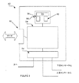
図1は、本発明の一実施形態による、流量制御装置30である。流量制御装置30は、流れを受けるための注入口32と、流れを流通システムの他の構成要素に導く流出口34と、狭窄部分36(例えば、オリフィス板、小口径チューブ、または当技術分野で公知の他の狭窄箇所)と、上流圧力を測定するように構成されている狭窄部分36の上流にある圧力センサー38(「上流圧力センサー」と呼ぶ)と、下流圧力を測定するために設定されている狭窄部分36の下流にある圧力センサー40(「下流圧力センサー」と呼ぶ)と、プロセッサとメモリと流体流量の決定および/または弁制御信号の生成に対するソフトウェア命令を含み得る制御器42と、流体流量を制限する弁制御信号に応答する弁44(例えば、絞り制水弁、ポペット弁、蝶形弁、空気圧で作動する弁、または当技術分野で公知の他の弁)とを含み得る。
FIG. 1 is a
上流圧力センサー38、および下流圧力センサー40は静電容量型、ピエゾ抵抗型、変換器型、または当技術分野で公知の他の圧力センサーであり得る。流量制御装置30を流れる流体にさらされている上流圧力センサー38および下流圧力センサー40の一部は、その流体に関して化学的に不活性であり得る。制御器42は、上流圧力センサー38、下流圧力センサー40、および弁44とに、例えば電気的接続を介して連結され得る。弁40は更に、弁制御信号を処理し弁制御信号に応答して弁44を開閉するために、マイクロコントローラのような構成部品を含み得る。
The
流体(気体、または液体)は注入口32において、流量制御装置30に入り、弁44および狭窄部分36を通過し、流出口34において流量制御装置30から抜け出得る。上流圧力センサー38および下流圧力センサー40は、上流圧力信号46および下流圧力信号48を生成し得、それぞれ上流圧力センサー38および下流圧力センサー40での圧測定を表すデジタル信号またはアナログ信号であり得る。
Fluid (gas or liquid) can enter the
制御器42は、例えばコンピュータ可読媒体に記憶されているソフトウェア命令を使用して、上流圧力センサー38および/または下流圧力センサー40によって測定された圧力に基づいた望ましい流量を達成するために、弁制御信号50を生成して弁44を開閉することができる。本発明の一実施形態によると、制御器42は上流圧測定と下流圧測定との差異を決定できる。差異は、上流圧力センサー38と下流圧力センサー40とでの圧測定の差のどのような表示でもよい。例えばその差異は、圧力値(例えば100Pa)または特定の電圧値(例えば100mV)を有する信号、または圧測定間の差を表す他のどのような形式でも表すことができる。制御器42は、どのような制御方式(例えば、比例積分(PI)制御方式、比例積分微分(PID)制御方式、または当技術分野で公知または開発された他のどのような方式)にも応じて弁制御信号50を生成するために差異と設定点とを比較することができる。本発明の一実施形態によると、設定点は、入力質量または体積流量に基づいた較正曲線多項式から決定され得る。制御信号50に基づいて、弁44は流量を制限するために開閉できる。図1の流量制御器は一例として提供されていることに留意されたい。
The
図2は流量制御装置30の一実施形態の図表示である。流量制御装置30は、流れを受ける注入口32と、流れを流通システムの他の構成要素に導く流出口34と、注入口32から流出口34へと流体を導く流路35と、狭窄部分36と、上流圧力センサー38と、下流圧力センサー40と、弁制御信号を生成する制御器42と、弁制御信号に応答して流体流量を制限する弁44とを含み得る。
FIG. 2 is a diagrammatic representation of one embodiment of the
制御器42は、上流圧力センサー38および下流圧力センサー40から、それぞれのセンサーにおける測定圧力を表す信号を受けることができる。その信号は、ビットが測定された圧力を表すようにまたは当技術分野で公知の他の方式で、電圧レベルによって、測定された圧力を表すことができるアナログまたはデジタル信号であり得る。制御器42は測定された圧力間の差異を、例えば差異信号の生成および/または圧力差の計算によって決定できる。制御器42は、差異に基づいた、または上流および/または下流圧力センサーから受けた圧力信号に基づいた弁制御信号を生成できる。弁44は受けた弁制御信号に応答して開閉できる。
The
図3は制御器42の一実施形態の図表示である。制御器42は上流圧力センサーおよび下流圧力センサーからの信号を受けるための、および受けた信号をデジタル形式に変換するためのアナログデジタル(A/D)変換器52を含み得る。プロセッサ54(例えば、Santa Clara、CaliforniaのIntel Corporationによる8051プロセッサのようなCPU、ASIC、Chandler、ArizonaのMicrochip TechnologiesによるPIC 18c452プロセッサのようなRISCプロセッサ、または他のプロセッサ)は、A/D変換器52から、測定した圧力を表すデジタル値を受け、差異を計算できる。差異、または上流か下流のいずれかのセンサーから測定された圧力に基づいて、プロセッサ54は流体流量を制限するためにどれだけ弁を開閉すべきかを表すデジタル制御信号を生成できる。A/D変換器52はデジタル値をアナログ弁制御信号に変換でき、アナログ弁制御信号を弁に送れる。
FIG. 3 is a diagrammatic representation of one embodiment of
プロセッサ54は、コンピュータ可読メモリ58(例えば、EEPROM、RAM、ROM、フラッシュメモリ、磁気記憶装置、光学式記憶装置、または当技術分野で公知の他のコンピュータ可読メモリ)上の制御プログラム56を含み得る制御プログラムを実行することによってデジタル制御信号を生成でき、そのメモリはプロセッサ54によってアクセス可能である。動作の一態様にて、制御アルゴリズムは、流量設定点入力およびコンピュータ可読媒体58に記憶されている較正データ60に基づいて差圧設定点を計算できる。制御プログラムは、測定された圧力間の差異に基づいてデジタル制御信号を計算するために特定の設定点と較正データを使い得る。他の動作の様態にて、制御アルゴリズムは、米国特許出願第10/777,300号に記載の通り、デジタル制御信号を計算するために上流または下流圧力センサーで測定された圧力を使い得る。
The
制御アルゴリズムは、PID、オフセット付きで変更されたPID、または当技術分野で公知の他の制御アルゴリズムを含むがこれらに制限されるものでない当技術分野で公知のいずれかの制御方式を使って、特定の動作の態様に対してデジタル制御信号を計算できる。その基本動作は誤り信号を生じる。その誤り信号は次に、特定の弁に対して補正される。補正された誤り信号はA/D変換器52によってデジタル形式からアナログ信号に変換され、結果として生じるアナログ信号は、制御弁を新しい位置に動かす電圧電流変換器へと送られる。
The control algorithm may be any control scheme known in the art including, but not limited to, PID, PID modified with offset, or other control algorithms known in the art, Digital control signals can be calculated for specific modes of operation. Its basic operation produces an error signal. That error signal is then corrected for the particular valve. The corrected error signal is converted from a digital form to an analog signal by A /
較正データ60は、例えば較正曲線を表す一つまたは複数の多項式に対する係数、および多項式を特定の条件に適用するための一つまたは複数の補正因子を含み得る。その多項式は、差異流れ制御に対する較正曲線、および/または単一圧力センサー制御に対する較正曲線を表し得る。本発明の一実施形態によると、制御器42は、図6と併せて以下に記載の通り、較正データを更新するために較正プログラム62を含み得る。
The calibration data 60 may include, for example, coefficients for one or more polynomials that represent a calibration curve, and one or more correction factors for applying the polynomials to particular conditions. The polynomial may represent a calibration curve for differential flow control and / or a calibration curve for single pressure sensor control. According to one embodiment of the present invention, the
制御器42は更なる入出力機能を含み得る。例えば、制御器42は、更新制御プログラム56、較正データ60または較正プログラム62等の管理機能をサポートするインターフェースを有し得る。加えて、制御器42は、他の流量制御装置、管理コンピュータ、またはネットワークを介して通信可能な他の装置と通信するためのネットワークインターフェース(例えば、インターフェース64)を含み得る。制御プログラム56および較正プログラム60は、単一セットのコンピュータ命令を含み得るか、別個のプログラムである得るか、同一プログラムのモジュールであり得るか、または当業者に理解され得る任意の適切なプログラムアーキテクチャーによってもインプリメントされ得ることに留意されたい。更に、図3の制御器は、例として提供されており、他の制御器が使用され得ることに留意されたい。
図4は、例えば、制御器のプロセッサによって実行できる一セットのコンピュータ可読命令としてインプリメントできる制御ルーチンの一実施形態を示す。ステップ102において、制御器は達成すべき目標質量流量または体積流量を受け得る。制御器は、設定点を導き出すために較正データを受けた流量に適用し得る(ステップ104)。
FIG. 4 illustrates one embodiment of a control routine that can be implemented, for example, as a set of computer-readable instructions that can be executed by a controller processor. In
本発明の一実施形態によると、制御器はn次多項式を流量に適用することによって設定点を決定できる。n次多項式の適用は、流量制御装置が機能する状態に対する式を補正するために較正曲線および補正因子に基づいて多項式を適用することを含み得る。補正因子決定の一実施形態は図6と併せて記載されている。 According to one embodiment of the invention, the controller can determine the set point by applying an nth order polynomial to the flow rate. The application of the nth order polynomial may include applying a polynomial based on a calibration curve and a correction factor to correct the equation for the state in which the flow controller functions. One embodiment of correction factor determination is described in conjunction with FIG.
ステップ106において、制御器は、例えばアナログデジタル変換器から、上流および下流圧力信号を読み取ることができる。この時点で、その上流および下流圧力信号は、圧力センサーによって作り出されたアナログ電圧を表す電圧サンプリング(例えば、デジタルサンプリング)であり得る。制御器は受けたサンプリングを圧力値に変換できる。ステップ108において、制御器は上流および下流の圧力示度から差圧を計算できる。
In
ステップ110において、制御器は差圧と設定点を比較できる。差圧が設定点と等しくない場合、制御器はステップ112において、差圧と設定点の違いに基づいて誤り信号を生成し、特定のセンサーからの圧力(例えば、下流センサーから測定された圧力)に基づいて誤り増幅率を計算できる。逆に、流量が設定点と等しい場合、制御器は測定された圧力間の違いに基づいて誤り増幅率を計算できる(ステップ114)。誤り増幅率は、低圧での低信号値を補うために誤り信号に加えられ得る。
In
ステップ122において、制御器は弁増幅率を決定できる。弁増幅率は、現在位置に比例して弁に適用される信号の増幅率を調整する。増幅率は例えば、メモリに記憶されている増幅率曲線から決定され得る。増幅率曲線は、システムが弁間の変動を補正することを可能にする。特定の弁の変動に対して補正することに加えて、弁増幅率曲線はまた、行過ぎ量、不足量、および応答時間を補うことができる。本発明の一実施形態によると、感度因子は、弁の応答を遅らせたり早めたりするために弁増幅率曲線に適用され得る。 In step 122, the controller can determine the valve gain. The valve gain adjusts the signal gain applied to the valve in proportion to the current position. The amplification factor can be determined from, for example, an amplification factor curve stored in the memory. The gain curve allows the system to compensate for variations between valves. In addition to compensating for specific valve variations, the valve gain curve can also compensate for overshoot, deficit, and response time. According to one embodiment of the present invention, a sensitivity factor can be applied to the valve gain curve to delay or speed up the valve response.
制御器はステップ124において、誤り信号、弁増幅率、および当業者に理解され得る他の因子に基づいて制御信号を出力し得る。制御信号は、差圧を設定点に近づけるために弁を開閉するよう命令し得る。請求項4の制御アルゴリズムはほんの一例として提供されているに過ぎず、当技術分野で公知の任意の制御アルゴリズムが利用されることに留意されたい。更には、圧力差に基づいた流れ制御も例として提供され、本発明の他の実施形態は、単一センサーまたは他のスキームに従った他のセンサーの圧力に基づいて流れを制御する。PCT出願PCT/US03/22579、米国特許出願第10/777,300号、および米国特許出願第10/779,009号は、本発明の実施形態によって採用され得る他の制御アルゴリズムを記載している。
The controller may output a control signal in
図5は流通装置30を較正するためのシステム200の一実施形態の図表示である。システム200において、流通装置30はそれが作動するシステム、またはそれが作動するシステムをシミュレートするテストシステムにインストールされ得る。流通装置30は、例えばポンプ、フィルターまたは他の流れ構成要素、および流れ構成要素をも含み得る下流流路に接続され得る。システム200は更に、データ転送媒体(例えば、バス、コネクタ、ネットワーク、または当技術で公知の他のデータ転送媒体)を介して流量制御器30に接続されている較正コンピュータ202(例えば、ラップトップ、デスクトップ、PDA、または当技術分野で公知の他のコンピュータデバイス)を含み得る。流量制御装置30の制御器(例えば制御器42)はデータ転送媒体を介して較正コンピュータ202にデータを通信し、およびその較正コンピュータ202からデータを受信し得る。
FIG. 5 is a diagrammatic representation of one embodiment of a
流通装置30は、例えば較正データ60の一部として記憶され得る、補正因子を計算する較正プログラム(例えば、図3の較正プログラム62)を含み得る。較正コンピュータ202は、較正プログラムに対するグラフィカルユーザーインターフェース(「GUI」)206、または他のインターフェースを表示するインターフェースプログラムを含み得る。較正コンピュータ202は、較正プログラムへとユーザーから受けた入力を通信でき、ユーザーに出力を表示できる。本発明のこの実施形態では、較正コンピュータ202は単に、流通装置30に記憶された較正プログラムに対してインターフェースを提供する。本発明の他の実施形態によると、較正コンピュータ202は較正プログラムを含み、単に較正データを流量制御器30へとアップロードし得る。補正因子、感度因子、または他の較正データが計算される所は、必要に応じてまたは特定のインプリメンテーションに対しての要望に応じて変わり得る。
本発明の一実施形態によると、流量制御器30がシステム200にインストールされる前に、較正曲線は流量制御器30に対して確立され得る。これは例えば、イソプロピルアルコール(「IPA」)または他の試験液等の試験液、およびテストシステムを使ってなされ得る。その較正曲線は当技術分野で公知の任意の方法によって確立され得る。一実施形態によると、様々な差圧に対する流量が決定され得る。例えば、流量制御器30に対して表1のデータを作り出すために様々な差圧で15のサンプルが取られると仮定する。
According to one embodiment of the present invention, a calibration curve may be established for the

ΔP=ax2+bx+c [式1]
更に具体的には、以下のとおりである。
ΔP=1.64237660x2+7.950469544x−.011737883 [式2]。
ΔP = ax 2 + bx + c [Formula 1]
More specifically, it is as follows.
ΔP = 1.64237660x 2 + 7.950469544x−. 011737883 [Formula 2].
多項式の係数(すなわちa、b、およびc)は製造業者または第三者によって流量制御装置30に記憶され得るか、あるいは別の形で提供され得る。較正曲線は任意の曲線フィッティングスキームを含み、当技術分野で公知の任意の形から導き出され、他のn次多項式によって表され得ることに留意されたい。加えて、多項式はゼロy切片に押しやられ得る。この場合、c項(例えば、−.00111737883))は省かれ、aおよびb項は曲線フィットに対して調整され得る。多項式をゼロy切片に押しやることは、より高い粘性プロセス流体またはより大きな圧力低下装置に対する曲線の曲がり具合を最小限にするのに役立つ。
The polynomial coefficients (i.e., a, b, and c) can be stored in the
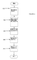
実際には、流量制御装置30がインストールされているプロセス流体およびシステムは、試験液およびテストシステムとは異なる。これを補うために、較正プログラムは流量制御装置に対する補正因子を決定し得る。図6は、様々なプロセスパラメータおよびプロセス流体を説明するための較正データのアップデート方法の一実施形態を示すフローチャートである。図6の目的のために、流量制御器は作動するシステム、または実質的に同様のシステム(例えば、それが作動するシステムをシミュレートする試験装置)にインストールされていると仮定する。図6のプロセスは、流量制御器上、または流量制御器と通信し得るコンピュータ(例えば、較正コンピュータ202)上の較正プログラムによってインプリメントされ得る。
In practice, the process fluid and system in which the
ステップ302において、最大差圧テストは、流量制御器が作動すると予測される最大差圧を決定するために行われ得る。ステップ302のために、較正プログラムは、流体の流れの差圧が供給時間に相対的な全質量または体積示度に影響し得る開始および供給終了効果の安定化および最小限化を可能にするのに十分なように、第一期間の間(t1)(例えば、10秒または他の任意に選択した時間)、流量制御器の弁を最大開放位置まで開く。弁が最大限開いている場合の上流圧力センサーと下流圧力センサーの圧力の差異は最大差圧(ΔPmax)である。ΔPmaxは作動中に流量制御器が受けると予測される最大差圧を表す。
In
流量制御器の圧力センサーが、設計された最大圧力を有する場合(「最大作動圧力」)、コンフィギュレーションプログラムは最大差圧をセンサーの最大作動圧力が上回るのを防ぐレベルに定めることによって、最大差圧テスト中のこれを補償し得る。例として、上流圧力センサーが30psiの最大作動圧力を有するが流量制御器弁を完全に開くことは上流圧力センサーの圧力が30psiを上回らせてしまう場合、コンフィギュレーションプログラムは上流圧力センサーの圧力を30psi以下、例えば28psiにする弁設定を選択し得る。この場合、コンフィギュレーションプログラムは上流圧力をモニタリングし、上流圧力が28psiまたは他の既定圧力制限になるまで弁を開く。上流圧力が28psiまたは他の圧力制限の場合における圧力差は、最大圧力差ΔPmaxとして選択できる。流通装置は更に、ΔPmaxのいくらかの比率である流量においての流通装置に対する最大流量を定め得る。例えば、コンフィギュレーションプログラムは、最大流量を.95ΔPmaxにおいて起こる流量に定め得る。 If the flow controller pressure sensor has a designed maximum pressure (“maximum operating pressure”), the configuration program sets the maximum differential pressure to a level that prevents the sensor's maximum operating pressure from being exceeded. This can be compensated for during the pressure test. As an example, if the upstream pressure sensor has a maximum operating pressure of 30 psi, but fully opening the flow controller valve would cause the upstream pressure sensor pressure to exceed 30 psi, the configuration program would set the upstream pressure sensor pressure to 30 psi. In the following, for example, a valve setting of 28 psi may be selected. In this case, the configuration program monitors the upstream pressure and opens the valve until the upstream pressure reaches 28 psi or some other predetermined pressure limit. The pressure differential when the upstream pressure is 28 psi or other pressure limit can be selected as the maximum pressure differential ΔP max . The flow device may further define a maximum flow rate for the flow device at a flow rate that is some ratio of ΔP max . For example, the configuration program may set a maximum flow rate. The flow rate occurring at 95ΔP max can be set.
故に、コンフィギュレーションプログラムは、弁が最大限開いているときに受ける差圧、または既定圧力制限以下で上流または下流センサーにおける圧力を維持する差圧として最大差圧を選択できる。設定点が最大圧力差を上回ってしまう流量が後に選択された場合、流量制御器はエラーを返すか、または単に最大差異流量を設定点として使い得る。 Thus, the configuration program can select the maximum differential pressure as the differential pressure experienced when the valve is fully open, or as the differential pressure that maintains the pressure at the upstream or downstream sensor below a predetermined pressure limit. If a flow rate at which the set point exceeds the maximum pressure differential is later selected, the flow controller may return an error or simply use the maximum differential flow as the set point.
ステップ304において、実験的流量は流量制御器に対して決定され得る。較正プログラムは、本発明の一実施形態によると、最大差圧未満の非最大差圧(ΔPtest)を有する流れを作り出すために第二期間(t2)の間、弁を開くように命令し得る。本発明の一実施形態によると、ΔPtestはΔPmaxの約半分となり得る。弁はこの例で、流れが釣り合うのに十分なように、10秒または他の期間の間、ΔPtestがΔPmaxの半分となるように開かれ得る。t2の終わりにおいて、流量制御器によって供給された流体(z)の量が決定され得る。実験的流量(xemp)は以下によって決定され得る。
xemp=z/t2 [式3]。
In
x emp = z / t 2 [Formula 3].
較正プログラムはステップ306において、xempをn次多項式に対する流量として使って、計算された差圧(ΔPcalc)を決定し得る。
ΔPcalc=axemp 2+bxemp+c [式4]
式2からの係数例を使って、上記式は以下となる。
ΔPcalc=1.64237660xemp 2+7.950469544xemp−.011737883 [式5]
例えば、ステップ304がΔPcalc=13に対してxemp=2.72g/秒という結果になる場合、ΔPcalcは33.81と等しい。
The calibration program may determine the calculated differential pressure (ΔP calc ) at
ΔP calc = ax emp 2 + bx emp + c [Formula 4]
Using the example coefficients from
ΔP calc = 1.64237660x emp 2 + 7.950469544x emp -. 011737883 [Formula 5]
For example, if
較正曲線に対する補正因子は、ステップ308において以下によって決定され得る。
F=ΔPtest/ΔPcalc[式6]
前回の例から引き続き、補正因子は約.38であり得る。補正因子は、試験流体を使って生成したn次多項式曲線を調整するために使われ得る。補正因子は、試験流体とプロセス流体との間の違い、および流量制御器がインストールされているシステムと制御器が較正されていたシステムとの違いを補い得る。補正因子は、例えば所定の流量に対して設定点等の圧力差を決定するときに適用され得る。流量制御器は補正された圧力差(ΔPcorr)を以下のように決定し得る。
ΔPcorr=F(ax2+bx+c) [式7]。
A correction factor for the calibration curve may be determined in step 308 by:
F = ΔP test / ΔP calc [Formula 6]
Continuing from the previous example, the correction factor is approximately. 38. The correction factor can be used to adjust the nth order polynomial curve generated using the test fluid. The correction factor may compensate for the difference between the test fluid and the process fluid, and the difference between the system where the flow controller is installed and the system where the controller was calibrated. The correction factor can be applied, for example, when determining a pressure difference such as a set point for a given flow rate. The flow controller may determine the corrected pressure difference (ΔP corr ) as follows:
ΔP corr = F (ax 2 + bx + c) [Formula 7].
ステップ310において、較正プログラムは較正データを記憶できる。本発明の一実施形態において、n次多項式の係数は既に保存されることから、これは単に補正因子を保存することによって可能となる。本発明の他の実施形態によると、較正曲線に対する新しい係数が記憶され得る(例えば、Fa、Fb、およびFc)。補正された較正曲線はまた、当業者に理解され得る任意の他の形で記憶され得る。また、複数の補正因子および/または多項式は単一の流量制御器に記憶され得、その流量制御器が様々な条件下で使われることを可能にしていることに留意されたい。加えて、較正プログラムはその装置に対する最大流量(例えば、.95ΔPmaxまたは他の最大流量において起こる流量)を保存できる。上記の例では、一つの実験的テストのみがFを計算するために論じられているが、複数のテストが使われ得る。例えば、流通装置は、ΔPtest1、ΔPtest2、ΔPtest3においての流れに、それぞれF1、F2、そしてF3を計算させるよう構成され得る。F1、F2、そしてF3はその次にFを作り出すために平均化され得る(または他の形で使われ得る)。他の実施形態によると、F1、F2、そしてF3は、流通装置が流れを制御または監視しているときはΔPの違った範囲において適用され得る。故に、複数のテストが補正因子または複数の補正因子を計算するために行われ得る。加えて、複数の実験的テストは、それぞれの係数に対する補正因子が見られ得るように行われ得る。
ΔPcorr=F1ax2+F2bx+F3c [式8]。
In step 310, the calibration program can store calibration data. In one embodiment of the invention, this is made possible simply by storing the correction factor, since the coefficients of the nth order polynomial are already stored. According to other embodiments of the invention, new coefficients for the calibration curve may be stored (eg, Fa, Fb, and Fc). The corrected calibration curve may also be stored in any other form that can be understood by those skilled in the art. It should also be noted that multiple correction factors and / or polynomials can be stored in a single flow controller, allowing the flow controller to be used under a variety of conditions. In addition, the calibration program can store a maximum flow rate for the device (eg, a flow rate occurring at .95ΔP max or other maximum flow rate). In the above example, only one experimental test is discussed for calculating F, but multiple tests can be used. For example, the distribution device can be configured to cause the flows in ΔP test1 , ΔP test2 , ΔP test3 to calculate F 1 , F 2 , and F 3 , respectively. F 1 , F 2 , and F 3 can then be averaged (or used in other ways) to produce F. According to other embodiments, F 1 , F 2 , and F 3 can be applied in different ranges of ΔP when the flow device is controlling or monitoring the flow. Thus, multiple tests can be performed to calculate a correction factor or multiple correction factors. In addition, multiple experimental tests can be performed such that a correction factor for each coefficient can be found.
ΔP corr = F 1 ax 2 + F 2 bx + F 3 c [Equation 8].
更には、図14と併せて論じられるように、複数のテストが補正因子無しの曲線を作り出すために行われ得る。 Furthermore, as discussed in conjunction with FIG. 14, multiple tests can be performed to create a curve without a correction factor.
一部の例では、入力流量を設定点に変換するための式7の使用は、入力した流量と到達した実際の流量との間にほんのわずかなオフセットを生む結果になるかもしれない。例えば、目標流量は100mL/秒、しかし流量制御器は補正因子の適用後も103mL/秒を供給する、と仮定する。この場合、このオフセットを説明するために割合補正が決定され得る。
In some examples, the use of
本発明の一実施形態によると、割合補正は、目標流量を流量制御器に提供することによって決定され得る。流量制御器は、式7に基づいて設定点圧力差を決定でき、弁を開いて設定点圧力差に到達するために制御アルゴリズムを設定点圧力差に適用し得る。弁は第三期間(t3)の間、例えば10秒間開かれ得、流量制御器によって供給される流体の量が測定され得る。このことから、実際の流量が決定され得る。較正プログラムは、流れ補正を決定するためにこの流量を目標流量と比較し得る。上記の例において、流れ補正は−3mL/秒になる。その流れ補正はその次に、流量制御器に提供されたそれぞれの目標流量に適用され得る。
According to one embodiment of the invention, the rate correction can be determined by providing a target flow rate to the flow controller. The flow controller can determine the set point pressure difference based on
較正プログラムの一実施形態はまた、感度因子を示唆し得る。感度因子は、流量制御器の応答時間が増減するように制御ループによって使われる弁増幅率曲線に適用され得る。応答時間とは、信号が流通装置に送られるときから流量制御器が設定点に至るときまでの時間である。感度因子とは、応答時間が依存している弁に対する増幅率値である。感度因子が高ければ高いほど応答時間が早くなる。制御器は基準感度因子(SCbase)を有するよう構成され得る。流量制御器の応答時間(tresp)が第一応答時間(例えば、.4秒、または他の任意に定義された応答時間)よりも短い場合、または第二応答時間(例えば、.8秒、または他の任意に定義された応答時間)よりも長い場合、較正プログラムは、流量制御器の応答時間を第一および第二応答時間の範囲内に持ってくる新感度因子(SCsug)を示唆し得る。感度因子は、感度を増減するための制御アルゴリズムの単一パラメータまたは様々なパラメータを調整するために使われ得るということに留意されたい。 One embodiment of the calibration program may also suggest a sensitivity factor. The sensitivity factor can be applied to the valve gain curve used by the control loop to increase or decrease the response time of the flow controller. Response time is the time from when the signal is sent to the flow device until when the flow controller reaches the set point. A sensitivity factor is an amplification factor value for a valve on which the response time depends. The higher the sensitivity factor, the faster the response time. The controller may be configured to have a reference sensitivity factor (SC base ). If the flow controller response time (t resp ) is shorter than the first response time (eg, .4 seconds, or other arbitrarily defined response time), or the second response time (eg, .8 seconds, Or longer than other arbitrarily defined response times), the calibration program suggests a new sensitivity factor (SC sug ) that brings the flow controller response time within the first and second response times. Can do. Note that the sensitivity factor can be used to adjust a single parameter or various parameters of the control algorithm to increase or decrease sensitivity.
第一および第二応答時間は、例えば流量制御器の特徴に基づいて流量制御器製造者によって決定され得る。第一応答時間は十分に長くあり得、trespがそれよりも大きい、または等しい場合でも流量制御器は流れの中の顕著な振動を受けない。第二応答時間は、十分に短くあり得、trespがそれよりも小さい、または等しい場合でも、流れは設定点圧力差に素早く至り、応答時間は流量制御器によって出力される流体の容積に顕著には影響しない。 The first and second response times may be determined by the flow controller manufacturer based on, for example, flow controller characteristics. The first response time can be long enough so that the flow controller is not subject to significant oscillations in the flow even if t resp is greater than or equal to it. The second response time can be sufficiently short, even if t resp is smaller or equal, flow quickly reaches the set point pressure differential, and the response time is significant in the volume of fluid output by the flow controller. Does not affect.
SCsugの決定のために使われるアルゴリズムは、例えば流量制御器製造者による実験的に決定されたデータに基づいて確立され得る。SCsugの決定に対する例示的な式は例えば、以下を含み得る。
SCsug=SCbase−(SCbase*3*(.5−tresp)) [式9]
(trespが.4秒未満の場合)、そして、
SCsug=SCbase*(1+tresp−.6) [式10]
(trespが.8秒より大きい場合)。
The algorithm used for the determination of SC sug can be established based on experimentally determined data, for example by the flow controller manufacturer. Exemplary formulas for determining SC sug may include, for example:
SC sug = SC base - (. SC base * 3 * (5-t resp)) [ Equation 9]
(If t resp is less than .4 seconds) and
SC sug = SC base * (1 + t resp −0.6) [Formula 10]
(When t resp is greater than .8 seconds).
本発明の較正プログラムは故に、素早く、簡単に特定のプロセスシステムに対して流量制御器を較正し得る。本発明の実施形態はi)測定された流量xempおよび較正曲線多項式を使って計算された差圧(例えば、ΔPcalc)と、ii)xempをもたらした差圧(ΔPtest)とに基づいた補正因子の決定を含み得る。加えて、較正プログラムは流れ補正を決定し、感度因子を示唆し得る。 The calibration program of the present invention can therefore quickly and easily calibrate the flow controller for a particular process system. Embodiments of the present invention are based on i) a differential pressure calculated using a measured flow rate x emp and a calibration curve polynomial (eg, ΔP calc ) and ii) a differential pressure resulting in x emp (ΔP test ). Determination of other correction factors. In addition, the calibration program can determine flow corrections and suggest sensitivity factors.
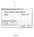
ユーザーはGUIまたはマンマシンインターフェース(「MMI」)を使って較正プログラムとインタラクトし得る。本発明の一実施形態によると、図5と併せて記載されているように、較正プログラムが流量制御装置の制御器内で実行される一方で、GUIは流量制御装置と連結しているラップトップコンピュータまたはデスクトップコンピュータ等の別のコンピュータにおいて提示され得る。図7Aは較正プロセスの始動するためのスクリーン700の例示的な実施形態を提供する。スクリーン700はユーザーに、流量制御装置は流体を10秒間(例えば、t1)供給し、ユーザーが「GO」ボタンを「クリック」することによって進められるようにする。図7Bは、期間t2の間供給を行い、期間t2の後に供給された液体の量(z)を入力するためのスクリーン702の例示的な実施形態を提供する。zから、較正装置はxempを決定し、ΔPcalcを計算し、Fを決定し得る。加えて、スクリーン702においてユーザーは感度因子の調整をすることができる。
A user may interact with the calibration program using a GUI or man-machine interface (“MMI”). According to one embodiment of the present invention, the calibration program is executed within the controller of the flow controller as described in conjunction with FIG. 5, while the GUI is connected to the laptop with the flow controller. It can be presented on another computer, such as a computer or a desktop computer. FIG. 7A provides an exemplary embodiment of a
図7Cおよび7Dはそれぞれスクリーン704および706を示す。スクリーン704および706は、ユーザーが供給プロセスを始動し、zを入力できるようにするスクリーン702の他の実施形態を表す。スクリーン704および706はまた、示唆された感度因子(SCsugg)を表示し、ユーザーに、示唆された感度因子を承認または拒否することを許可する。スクリーン704は、応答時間が長すぎる場合に、示唆された感度因子を示し、スクリーン706は、応答時間が短すぎる場合に、示唆された感度因子を示す。図7A−7Dのスクリーンはほんの一例として提供されるに過ぎず、どの様な適切なインターフェースでも提供され得ることに留意されたい。MMIもまた、較正プログラムおよび他の較正情報によって決定された最大流量を含む他の情報をユーザーに報告し得るということに留意されたい。
7C and 7D show screens 704 and 706, respectively.
本発明の実施形態が、主に差圧制御の観点から論じられてきた。しかしながら、本発明の実施形態はまた、単一圧力センサー制御に対しても利用され得るということに留意されたい。これは図6のプロセス中に特定のセンサーにおいての圧力をそれらの差圧に置き換えることによって可能となる。この場合、較正曲線は試験条件下で試験流体に対する特定の圧力センサー(例えば、上流および下流圧力センサー)によって読まれた圧力(P)に基づいて確立される。差圧較正曲線と同様に、単一圧力較正曲線はn次多項式によって表され得る。その場で、較正プログラムがPmaxを決定し得る。較正プログラムはまた、供給プロセスをt2の間、Pmax未満のPtestにおいて行い、供給された容積の量(z)を決定し得る。zおよびt2はxempを決定するのに使われ得る。n次多項式がPcalcを決定するためにxempに適用され得る。補正因子FはPtestのPcalcに対する比率に基づいて決定され得る。 Embodiments of the present invention have been discussed primarily in terms of differential pressure control. However, it should be noted that embodiments of the present invention can also be utilized for single pressure sensor control. This is made possible by replacing the pressure at specific sensors with their differential pressure during the process of FIG. In this case, the calibration curve is established based on the pressure (P) read by the particular pressure sensor (eg, upstream and downstream pressure sensors) for the test fluid under the test conditions. Similar to the differential pressure calibration curve, the single pressure calibration curve may be represented by an nth order polynomial. On the spot, the calibration program can determine P max . The calibration program may also perform the delivery process for t 2 at a P test less than P max to determine the amount of volume delivered (z). z and t 2 can be used to determine x emp . An nth order polynomial can be applied to x emp to determine P calc . The correction factor F can be determined based on the ratio of P test to P calc .
加えて、本発明の実施形態は、制御方法が上流および下流送信器間の送信時間の違いに基づいた超音波流量制御器に適用され得るということに留意されたい。較正プログラムは、送信時間(Δtmax)内の流量制御器に対する最大差を決定するために、ある期間(t1)流量制御弁を最大セッティングまで開き得る。較正プログラムはまた、設定送信時間差(Δttest)において設定時間(t2)の間供給を実行し得、供給される流体の量(z)を決定し得る。zおよびt2よりxempが決定され得る。流量制御器に対する較正曲線を表すn次多項式は、その流量に対する計算された時間差(Δtcalc)を決定するためにxempに適用され得る。補正因子はΔttestとΔtcalcとの比率に基づき得る。 In addition, it should be noted that embodiments of the present invention can be applied to an ultrasonic flow controller based on a difference in transmission time between upstream and downstream transmitters. The calibration program may open the flow control valve to a maximum setting for a period of time (t 1 ) to determine the maximum difference for the flow controller within the transmission time (Δt max ). The calibration program may also perform a supply for a set time (t 2 ) at a set transmission time difference (Δt test ) and determine the amount of fluid to be supplied (z). x emp can be determined from z and t 2 . An nth order polynomial representing a calibration curve for the flow controller can be applied to x emp to determine the calculated time difference (Δt calc ) for that flow. The correction factor may be based on the ratio of Δt test and Δt calc .
故に一実施形態によると、流通装置は、ΔP、P、Δtまたは他の流量を示す変数が試験値(例えば、ΔPtest、Ptest、Δttest)を有するように、流量を作り出すために弁を開くように命令され得る。実験的流量はある時間枠の間、その流れに対して決定され得る。較正曲線がその変数(例えば、ΔPcalc、Pcalc、Δtcalc)に対する計算値を決定するために、実験的流れに適用される。較正曲線に対する補正因子はその次に、試験値と変数の計算値とに基づいて決定され得る。 Thus, according to one embodiment, the flow device uses a valve to create a flow rate such that a variable indicating ΔP, P, Δt or other flow rate has a test value (eg, ΔP test , P test , Δt test ). Can be ordered to open. The experimental flow rate can be determined for that flow for a period of time. A calibration curve is applied to the experimental flow to determine the calculated value for that variable (eg, ΔP calc , P calc , Δt calc ). A correction factor for the calibration curve can then be determined based on the test value and the calculated value of the variable.
上記の例において、補正因子は依然として変わらないままである。本発明の一実施形態によると、補正因子は流量と共に変化し得る。この場合、較正プログラムは複数の実験的流量において差圧(ΔPtest)を決定し得る。例えば、そのΔPtestは、制御器がΔPtest1およびΔPtest2を与えるために流量範囲のハイエンドおよびローエンド付近の流量に対して決定され得る。F1およびF2は、対応する実験的流量に対するΔPcalc1およびΔPcalc2を使用し、式7より決定され得る。直線フィットまたは曲線フィットは、流量にわたるFの変化に対する式を展開するために行われ得る。この式、またはこの式に対する係数は、所定の流量に対して補正因子が決定され得るように流量制御器に記憶され得る。
In the above example, the correction factor remains unchanged. According to one embodiment of the present invention, the correction factor may change with flow rate. In this case, the calibration program may determine the differential pressure (ΔP test ) at multiple experimental flow rates. For example, the ΔP test can be determined for flow rates near the high end and low end of the flow range for the controller to provide ΔP test1 and ΔP test2 . F 1 and F 2 can be determined from
本発明の他の実施形態によると、流量制御装置は、流体の動的粘度(μ)および密度(ρ)または流体の動粘度(ν=μ/ρ)に基づいて素早く較正され得る。流量制御装置はまた、プロセス流体の動的粘度にのみ基づいて較正され得る。n次多項式として表現された較正流れ曲線を仮定すると以下となる。
ΔP=ax2+bx [式11]。
According to other embodiments of the invention, the flow control device can be quickly calibrated based on the dynamic viscosity (μ) and density (ρ) of the fluid or the kinematic viscosity of the fluid (ν = μ / ρ). The flow controller can also be calibrated based solely on the dynamic viscosity of the process fluid. Assuming a calibration flow curve expressed as an nth order polynomial:
ΔP = ax 2 + bx [Formula 11].
較正流れ曲線の係数は、補正された流れ曲線を生成するために、動的粘度、動的粘度および密度または動粘度に従って、調整され得る。
ΔP=acorx2+bcorx [式12]。
The coefficients of the calibration flow curve can be adjusted according to dynamic viscosity, dynamic viscosity and density or kinematic viscosity to generate a corrected flow curve.
ΔP = a cor x 2 + b cor x [Formula 12].
式11の係数は粘度ベースの補正因子を使って補正される。最初に動粘度または動的粘度および密度を使って較正を検討すると、較正流れ曲線の係数は以下のように調整される。
acor=a*((ν*D1)+D0) [式13]
bcor=b*(b*(ν.5*E1)+E0) [式14]
または
acor=a*(((μ/ρ)*D1)+D0) [式15]
bcor=b*(b*((μ/ρ).5*E1)+E0) [式16]。
The coefficient in Equation 11 is corrected using a viscosity-based correction factor. When considering calibration using kinematic viscosity or dynamic viscosity and density first, the coefficients of the calibration flow curve are adjusted as follows:
a cor = a * ((ν * D 1 ) + D 0 ) [Formula 13]
b cor = b * (b * (ν .5 * E 1 ) + E 0 ) [Formula 14]
Or a cor = a * (((μ / ρ) * D 1 ) + D 0 ) [Formula 15]
b cor = b * (b * ((μ / ρ) .5 * E 1 ) + E 0 ) [Formula 16].
ここで、D0、D1、E0、およびE1は粘性相関変数である。粘性相関因子は本質的には、特定のプロセス流体に対する較正流れ曲線を調整するために較正流れ曲線の係数に適用する一セットの補正因子である。粘性相関変数展開の一実施形態は図8−10と併せて以下に論じられている。 Here, D 0 , D 1 , E 0 , and E 1 are viscosity correlation variables. The viscosity correlation factor is essentially a set of correction factors that are applied to the coefficients of the calibration flow curve to adjust the calibration flow curve for a particular process fluid. One embodiment of the viscous correlation variable evolution is discussed below in conjunction with FIGS. 8-10.
図8は圧力差対流量の脱イオン水(「DIW」)、N1(較正オイル)、IPA(イソプロピルアルコール)、S3(較正オイル)、そしてS6(較正オイル)に関する実例データの表800である。それぞれの流体に対して、表800は動的粘度μ(DIWに対して802を参照)、密度ρ(DIWに対して804を参照)、実例圧力差値の列(列806)、および対応する実例流量の列(列808)を提供する。表2は曲線フィットに基づいたそれぞれの流体に対する、ゼロに押しやられた、n次多項式に対する係数(aおよびb)を表示する。 FIG. 8 is a table 800 of example data for pressure differential versus flow rate deionized water (“DIW”), N1 (calibration oil), IPA (isopropyl alcohol), S3 (calibration oil), and S6 (calibration oil). For each fluid, table 800 shows dynamic viscosity μ (see 802 for DIW), density ρ (see 804 for DIW), column of example pressure differential values (column 806), and corresponding. An example flow column (column 808) is provided. Table 2 displays the coefficients (a and b) for the nth order polynomial, forced to zero, for each fluid based on the curve fit.
ΔP=.00434424x2+.05974385x [式17]
上記の係数は、図8のデータに基づいた2次多項式に対するMicrosoft Excel の「LINEST」機能を使って導き出されたということに留意されたい。しかし、当技術分野で公知の任意の曲線フィッティングスキームを使ってよい。
ΔP =. 00434424x 2 +. 0594385x [Formula 17]
Note that the above coefficients were derived using Microsoft Excel's “LINEEST” function for second order polynomials based on the data of FIG. However, any curve fitting scheme known in the art may be used.
例示の目的で、ここで、DIWに対する流れ曲線は較正流れ曲線だと仮定する。互いの化学物質の流れ曲線の一次および二次係数の各々は、それぞれの較正流れ曲線の一次または二次係数によって除算され得る。言い換えれば、aotherはaDIWによって除算され得、botherはbDIWによって除算され得、以下の実例結果を生み出し得る。
aN1/aDIW=.75767
bN1/bDIW=.8303
aIPA/aDIW=.8601
bN1/bDIW=2.2140
aS3/aDIW=1.240
bS3/bDIW=2.7604
aS6/aDIW=2.1425
bS6/bDIW=4.8568。
For illustrative purposes, it is assumed here that the flow curve for DIW is a calibration flow curve. Each of the first and second order coefficients of each other's chemical flow curve may be divided by the first and second order coefficients of the respective calibration flow curve. In other words, a other can be divided by a DIW and b other can be divided by b DIW , producing the following example results.
a N1 / a DIW =. 75767
b N1 / b DIW =. 8303
a IPA / a DIW =. 8601
b N1 / b DIW = 2.2140
a S3 / a DIW = 1.240
b S3 / b DIW = 2.7604
a S6 / a DIW = 2.1425
b S6 / b DIW = 4.8568.
図9は、aother/aDIW対動粘度(νまたはμ/ρ)のプロットとラインフィットを示す。図9に示されるとおり、上記で論じられた実例データに対して、
aother/aDIW=.1497ν+.5159 [式18]。
FIG. 9 shows a plot of a other / a DIW versus kinematic viscosity (ν or μ / ρ) and line fit. As shown in FIG. 9, for the example data discussed above,
a other / a DIW =. 1497ν +. 5159 [Formula 18].
上記の式13および15に戻って、粘度相関変数D0およびD1は、この例では、それぞれ.5159および.1497と等しい。
Returning to
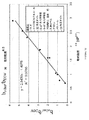
図10はbother/bDIW対動粘度の平方根(ν.5または(μ/ρ).5)のプロット示す。図6に示されるとおり、提供された実例データに対して、
bother/bDIW=1.8138ν.5−1.0848 [式19]。
Figure 10 shows a plot of b other / b square root of DIW to dynamic viscosity ([nu .5 or (μ / ρ) .5). As shown in FIG. 6, for the example data provided,
b other / b DIW = 1.8138ν . 5 -1.0848 [Equation 19].
故に上記式14および16において、粘度相関変数E0およびE1は、この例では、それぞれ−1.0848および1.8138と等しい。 Thus, in equations 14 and 16 above, the viscosity correlation variables E 0 and E 1 are equal to −1.0848 and 1.8138, respectively, in this example.
上記式18および19は、任意の適切なラインフィッティング方法(例えば、最小二乗または他のラインフィッティングスキーム)を使って導き出され得るということに留意されたい。 Note that Equations 18 and 19 above can be derived using any suitable line fitting method (eg, least squares or other line fitting scheme).
較正流れ曲線の係数および粘度相関変数は、製造業者、第三者によって流量制御装置(例えば、流量制御装置30)に記憶され得るか、他の方法で提供され得る。上記図5の例のとおり、較正コンピュータ200は、ユーザーがGUIを使って流量制御装置30を構成できるように、流量制御装置30と接続され得る。本発明の一実施形態によると、ユーザーは動粘度または動的粘度および密度を入力し得る。較正コンピュータ200または流量制御装置30は、流れ曲線に対する補正された係数を決定するために粘性相関変数を適用する。新しい流れ曲線は、プロセス流体の動粘度に基づいて調整されるが、(例えば、n次多項式の補正された係数を記憶することによって)流量制御装置30に記憶され得る。流量制御装置30はその次に、補正された流れ曲線を使ってプロセス流体の流量を決定し得る。
The coefficients of the calibration flow curve and the viscosity correlation variables can be stored in the flow controller (eg, flow controller 30) by the manufacturer, a third party, or otherwise provided. As in the example of FIG. 5 above, the
同様に、製造業の流れ曲線は動的粘度に基づいて補正され得る。この場合、粘性相関変数は動粘度よりもむしろ動的粘度の曲線フィットに基づいて展開される。故に、補正された係数は以下のように表現され得る。
acor=a*((μ*D1)+D0) [式20]
bcor=b*(b*(μ.5*E1)+E0) [式21]。
Similarly, manufacturing flow curves can be corrected based on dynamic viscosity. In this case, the viscosity correlation variable is developed based on a curve fit of dynamic viscosity rather than kinematic viscosity. Therefore, the corrected coefficient can be expressed as:
a cor = a * ((μ * D 1 ) + D 0 ) [Formula 20]
b cor = b * (b * (μ .5 * E 1 ) + E 0 ) [Formula 21].
図11はacor/aDIW対動的粘度に対するプロットとラインフィットを示す。図11に示されるとおり、実例プロットに対して、
aother/aDIW=.3152μ+.6855 [式22]。
FIG. 11 shows a plot and line fit for a cor / a DIW versus dynamic viscosity. As shown in FIG. 11, for the example plot,
a other / a DIW =. 3152μ +. 6855 [Formula 22].
上記の式20に戻って、粘度相関変数D0およびD1は、この例では、それぞれ.6855および.3152と等しい。図11において、一部の流体(例えば、S6)は曲線からはずれて位置し得るということに留意されたい。これらテストポイントは曲線フィットの要素に入れられ得るか、または拒否され得る。
Returning to
図12はbcor/bDIW対動的粘度の平方根のプロットおよびラインフィットを示す。図12に示されるとおり、実例プロットに対して、
bother/bDIW=2.3438μ.5+1.4075 [式23]。
FIG. 12 shows a plot and line fit of b cor / b DIW versus square root of dynamic viscosity. As shown in FIG. 12, for an example plot,
b other / b DIW = 2.3438μ . 5 +1.4075 [Formula 23].
上記の式21に戻って、粘度相関変数E0およびE1は、この例では、それぞれ1.4075および2.3438と等しい。この場合もやはり、インプリメンテーション次第で曲線からはずれて位置するテストポイントは曲線フィットの要素に入れられ得るか、または拒否され得る。図11および12に対するデータは20インチ×.063インチ(.508メートル×.00160メートル)の内径圧力低下コイルを有する流量制御器を使って生成されたということに留意されたい。 Returning to Equation 21 above, the viscosity correlation variables E 0 and E 1 are equal to 1.4075 and 2.3438, respectively, in this example. Again, depending on the implementation, test points located off the curve can be entered into the curve fit element or rejected. Data for FIGS. 11 and 12 are 20 inches ×. Note that it was generated using a flow controller with a 063 inch (.508 meter x 0.000016 meter) internal pressure drop coil.
図13は特定のプロセス流体に対する流通装置を較正する方法の一実施形態を示すフローチャートである。本発明の実施形態は、流量制御装置および/または較正コンピュータにおいて起動している一つまたは複数のプロセッサによって実行され得るコンピュータ可読媒体(例えば、磁気ディスク、光ディスク、フラッシュメモリ、RAM、ROM、または他のコンピュータ可読媒体)に記憶されたソフトウェアプログラミングとしてインプレメントされ得る。 FIG. 13 is a flowchart illustrating one embodiment of a method for calibrating a flow device for a particular process fluid. Embodiments of the present invention can be implemented by a computer readable medium (eg, magnetic disk, optical disk, flash memory, RAM, ROM, or other) that can be executed by one or more processors running in a flow controller and / or calibration computer The computer programming readable medium may be implemented as software programming.
較正流れ曲線は、例えば対応するn次多項式の係数および粘度相関変数を読み込むことによって読み込まれる(ステップ1102)。ユーザーは、例えば動粘度、動的粘度、動的粘度および密度を含む流体パラメータを入力する(ステップ1104)。較正流れ曲線は、その次にプロセス流体の粘度に基づいて調整される(ステップ1106)。これは、例えば補正された流れ曲線を生成するために粘度相関変数を較正流れ曲線の係数に適用することによって可能となり得る。補正された流れ曲線は、流量制御装置が流体流量を決定するために補正された流れ曲線を使えるように、流量制御装置において記憶されている(ステップ1108)。加えて、補正された流れ曲線は、既に較正された流量制御器が交換されたとしても、補正された流れ曲線が新しい流量制御器にアップロードされ得るように較正コンピュータに記憶され得る。図13のステップは必要または要望に応じて繰り返され得る。 The calibration flow curve is read, for example, by reading the corresponding nth order polynomial coefficients and viscosity correlation variables (step 1102). The user enters fluid parameters including, for example, kinematic viscosity, dynamic viscosity, dynamic viscosity and density (step 1104). The calibration flow curve is then adjusted based on the viscosity of the process fluid (step 1106). This may be possible, for example, by applying a viscosity correlation variable to the coefficients of the calibration flow curve to generate a corrected flow curve. The corrected flow curve is stored at the flow controller so that the flow controller can use the corrected flow curve to determine fluid flow (step 1108). In addition, the corrected flow curve can be stored in the calibration computer so that the corrected flow curve can be uploaded to the new flow controller even if the already calibrated flow controller is replaced. The steps of FIG. 13 can be repeated as needed or desired.
本発明の実施形態は、流量計および質量流量制御器等の流通装置を素早く較正するシステムおよび方法を提供する。本発明の実施形態は、特定のプロセス流体およびシステムに対して、流量制御器が素早く較正されるのを可能にする。主に供給プロセスを制御する流量制御器の観点から論じられてきたが、本発明の実施形態は任意の流量制御器に適用され得る。流量制御器を素早く較正できるので、特定のシステムの中で最小限の遅れで流量制御器がスワップ可能となる。 Embodiments of the present invention provide systems and methods for quickly calibrating flow devices such as flow meters and mass flow controllers. Embodiments of the present invention allow the flow controller to be quickly calibrated for specific process fluids and systems. Although discussed primarily from the perspective of a flow controller that controls the feed process, embodiments of the present invention can be applied to any flow controller. Because the flow controller can be quickly calibrated, the flow controller can be swapped with minimal delay in a particular system.
加えて、一旦補正因子、流れ補正、および/または感度因子がシステム内の流量制御器に対して決定されると、それは例えば、較正コンピュータに記憶され得る。流量制御器がプロセスシステム内で同様の構成をした新しい流量制御器と交換された場合、補正因子、流れ補正および/または感度因子は較正プログラムを行うことなく新しい流量制御器にアップロードされ得る。これにより、流量制御器の素早い交換が可能になり得る。 In addition, once a correction factor, flow correction, and / or sensitivity factor is determined for a flow controller in the system, it can be stored, for example, in a calibration computer. If the flow controller is replaced with a new flow controller of similar configuration in the process system, the correction factor, flow correction and / or sensitivity factor can be uploaded to the new flow controller without running a calibration program. This may allow quick replacement of the flow controller.
以前に記載された実施形態において、製造流れ曲線はプロセス流体に対する実験的テストまたは粘度相関変数に基づいて調整される。本発明の他の実施形態によると、実験的テストは製造流れ曲線から独立している流れ曲線に対する二次多項式(または他のn次多項式)を生成するために行われ得る。 In the previously described embodiment, the production flow curve is adjusted based on experimental tests or viscosity correlation variables for the process fluid. According to other embodiments of the present invention, experimental testing may be performed to generate a second order polynomial (or other nth order polynomial) for the flow curve that is independent of the manufacturing flow curve.
図14は流通装置に対する流れ曲線を決定する方法の一実施形態を示すフローチャートである。図14の目的で、流量制御器はそれが作動するシステム、または実質的に同様のシステム(例えば、それが作動するシステムをシミュレートする試験装置)にインストールされていると仮定する。図14のプロセスは、流量制御器上、または流量制御器と通信し得るコンピュータ(例えば、較正コンピュータ202)上の較正プログラム(例えば、較正プログラム62)によってインプリメントされ得る。 FIG. 14 is a flowchart illustrating one embodiment of a method for determining a flow curve for a distribution device. For the purposes of FIG. 14, it is assumed that the flow controller is installed in the system in which it operates, or in a substantially similar system (eg, a test device that simulates the system in which it operates). The process of FIG. 14 may be implemented by a calibration program (eg, calibration program 62) on the flow controller or on a computer (eg, calibration computer 202) that may be in communication with the flow controller.
ステップ1402において、最大差圧テストは、流量制御器が作動すると予測される最大差圧を決定するために行われ得る。ステップ1402に対して、較正プログラムは、流体の流れの差圧が供給時間に相対的な全質量または体積示度に影響し得る開始および供給終了効果の安定化および最小限化を可能にするのに十分な第一期間(t1)(例えば、10秒または他の任意に選択した時間)の間、流量制御器の弁を最大開放位置まで開く。弁が最大限開いているときの上流圧力センサーと下流圧力センサーの圧力の差異は最大差圧(ΔPmax)である。ΔPmaxは作動中に流量制御器が受けると予測される最大差圧を表す。
In
流量制御器の圧力センサーが、設計された最大圧力を有する場合(「最大作動圧力」)、コンフィギュレーションプログラムは最大差圧をセンサーの最大作動圧力が上回るのを防ぐレベルに定めることによって、最大差圧テスト中のこれを補償し得る。例として、上流圧力センサーが30psiの最大作動圧力を有するが、流量制御器弁を完全に開くことは上流圧力センサーの圧力が30psiを上回らせてしまう場合、コンフィギュレーションプログラムは、上流圧力センサーの圧力を30psi以下、例えば28psiにする弁設定を選択し得る。この場合、コンフィギュレーションプログラムは上流圧力を監視し、上流圧力が28psiまたは他の既定圧力制限になるまで弁を開く。上流圧力が28psiまたは他の圧力制限のときの圧力差は、最大圧力差ΔPmaxとして選択され得る。流通装置は更に、ΔPmaxのいくらかの比率である流量においての流通装置に対して最大流量を定め得る。例えば、コンフィギュレーションプログラムは、最大流量を.95ΔPmaxにおいて起こる流量に定め得る。 If the flow controller pressure sensor has a designed maximum pressure (“maximum operating pressure”), the configuration program sets the maximum differential pressure to a level that prevents the sensor's maximum operating pressure from being exceeded. This can be compensated for during the pressure test. As an example, if the upstream pressure sensor has a maximum operating pressure of 30 psi, but fully opening the flow controller valve will cause the upstream pressure sensor pressure to exceed 30 psi, the configuration program The valve setting may be selected to be less than 30 psi, for example 28 psi. In this case, the configuration program monitors the upstream pressure and opens the valve until the upstream pressure reaches 28 psi or some other predetermined pressure limit. The pressure differential when the upstream pressure is 28 psi or other pressure limit may be selected as the maximum pressure differential ΔP max . The flow device may further define a maximum flow rate for the flow device at a flow rate that is some ratio of ΔP max . For example, the configuration program may set the maximum flow rate to. The flow rate occurring at 95ΔP max can be set.
ステップ1404において、複数の実験的テストが異なるテストΔPにおいて行われ得る。一実施形態によると、それぞれのテストΔPは、流通装置の作動範囲の様々な領域(例えば、完全閉鎖位置の近く、.5ΔPmaxの近く、およびΔPmaxの近く)に位置し得るが、任意のΔPが使える。例示の目的で、三つのテストΔPが使われ得る(ΔPtest1、ΔPtest2、ΔPtest3)。流通装置は特定の試験期間(t1、t2、t3)に対する各ΔPtestにおいて流れを作り出すように構成され得るが、それは各テストに対して同一または異なり得る。図6と併せて記載されたとおり、実験的テストに対する流量は供給された流体の量(z)および試験期間に基づいて測定され得る。故に、
xemp1=z1/t1[式24]
xemp2=z2/t2[式25]
xemp3=z3/t3[式26]。
In
x emp1 = z 1 / t 1 [Formula 24]
x emp2 = z 2 / t 2 [Formula 25]
x emp3 = z 3 / t 3 [Formula 26].
ステップ1406において、較正プログラムは、実験的テストのデータを使って流れ曲線の係数の値を求め得る。流れ曲線を表すために二次多項式の例を使うと、以下のとおりである。
ΔPtest1=Axemp1 2+Bxemp1+c [式27]
ΔPtest2=Axemp2 2+Bxemp2+c [式28]
ΔPtest3=Axemp3 2+Bxemp3+c [式29]。
In
ΔP test1 = Ax emp1 2 + Bx emp1 + c [Formula 27]
ΔP test2 = Ax emp2 2 + Bx emp2 + c [Formula 28]
ΔP test3 = Ax emp3 2 + Bx emp3 + c [Formula 29]
式29を使ってCの値を求めると、
C=ΔPtest3−Axemp3 2−Bxemp3 [式30]。
When the value of C is calculated using Equation 29,
C = ΔP test3 -Ax emp3 2 -Bx emp3 [ Expression 30].
式30のCを式28に入れてBの値を求めると、
B=((ΔPtest2−ΔPtest3)/(xemp2−xemp3))−A(xemp2+xemp3) [式31]。
When C in
B = ((ΔP test2 −ΔP test3 ) / (x emp2 −x emp3 )) − A (x emp2 + x emp3 ) [Formula 31].
式29のCおよび式30のBを使って式26のAの値を求めると、
Using C in Equation 29 and B in
係数の値を求める特定の順序が上に記載されているが、その係数は係数の値を求めることに対する任意の手順を使って決定され得ることに留意されたい。付加的な実験的テストが高次多項式の値を求めるため、または精度を増すために行われ得るということに更に留意されたい。なおその上に、曲線がゼロ切片を横切る場合、C=0なので二つの実験的テストのみを行うだけでよい。 It should be noted that although a specific order for determining coefficient values is described above, the coefficients can be determined using any procedure for determining coefficient values. It should be further noted that additional experimental tests can be performed to determine higher order polynomial values or to increase accuracy. Furthermore, if the curve crosses the zero intercept, C = 0, so only two experimental tests need be performed.
流通装置は複数の較正方法を可能にする較正プログラムを含み得る。故に、例えば較正プログラムは補正因子を導き出すための単一実験的テスト、図14と併せて記載されている二次多項式を導き出すための複数の実験的テスト、または流体の粘度に基づいて装置を較正する粘度相関因子を使って、流通装置を較正するように構成され得る。これは流量制御装置がユーザーによるユーザーの推奨方法を使って較正されるのを可能にする。例えば、時間または複数の実験的テストを実施する意向のないユーザーは、補正因子を展開するために単一実験的テストを採用でき、一方で別のユーザーは製造流れ曲線から独立している流れ曲線を展開するために複数の実験的テストを採用し得る。 The distribution device may include a calibration program that allows multiple calibration methods. Thus, for example, a calibration program may calibrate the device based on a single experimental test to derive a correction factor, multiple experimental tests to derive a second order polynomial described in conjunction with FIG. 14, or a fluid viscosity. The flow correlation device can be used to calibrate the flow device. This allows the flow controller to be calibrated using the user's recommended method by the user. For example, a user who does not intend to perform time or multiple experimental tests can adopt a single experimental test to develop the correction factor, while another user has a flow curve that is independent of the manufacturing flow curve. Multiple experimental tests can be employed to deploy
本発明の実施形態は、上流および下流プロセス構成要素が変わる場合、流量制御器が再構成される場合、配管が変えられる場合、あるいはプロセスシステムまたは流量制御器への他の変更がなされた場合、流量制御器が素早く再較正されることを可能にする。これはプロセスシステムが様々な流動範囲に適応するように簡単に再構成されることを可能にする。他の実施形態によると、流通装置は、単に動粘度または動的粘度および流体の密度を使って素早く較正され得る。 Embodiments of the present invention can be used when upstream and downstream process components change, when flow controllers are reconfigured, when piping is changed, or when other changes to the process system or flow controller are made. Allows the flow controller to be quickly recalibrated. This allows the process system to be easily reconfigured to accommodate various flow ranges. According to other embodiments, the flow device can be quickly calibrated simply using kinematic viscosity or dynamic viscosity and fluid density.
特定の実施形態を参照して本発明を記載したが、これらの実施形態は例証であり、本発明の範囲はこれらの実施形態に限定されるものではないということを理解されたい。上記の実施形態への多様なバリエーション、修正、追加、および改良が可能である。これらバリエーション、修正、追加、および改良は本発明の範囲に含まれると考えられる。 Although the invention has been described with reference to particular embodiments, it is to be understood that these embodiments are illustrative and that the scope of the invention is not limited to these embodiments. Various variations, modifications, additions, and improvements to the above embodiments are possible. These variations, modifications, additions and improvements are considered to be within the scope of the present invention.
Claims (62)
該流通装置を介する流体の流量を示す変数が試験値を有するように、該流体の流れを生成することと、
試験期間の間において該流体の実験的流量を決定することと、
較正曲線と該実験的流量とに基づいて、該流量を示す変数に対する計算値を決定することと、
該試験値と該計算値とに基づいて補正因子を決定することと、
該補正因子に基づいて該較正流れ曲線を補正することと
を包含する、方法。 A method for calibrating a distribution device comprising:
Generating the fluid flow such that a variable indicative of the flow rate of fluid through the flow device has a test value;
Determining an experimental flow rate of the fluid during a test period;
Determining a calculated value for a variable indicative of the flow rate based on a calibration curve and the experimental flow rate;
Determining a correction factor based on the test value and the calculated value;
Correcting the calibration flow curve based on the correction factor.
流量を示す変数の一つ以上の試験値を決定する命令と、
一つ以上の実験的流量と較正曲線に対応するn次多項式とに基づいて、該流量を示す変数に対する一つ以上の計算値を決定する命令と、
該流量を示す変数に対する該一つ以上の計算値と該一つ以上の試験値とに基づいて、一つ以上の補正因子を決定する命令と
を含む、コンピュータプログラム製品。 A computer program product comprising a set of computer instructions stored on a computer readable medium, the set of computer instructions being executable by a processor,
Instructions to determine one or more test values for a variable indicative of flow rate;
Instructions for determining one or more calculated values for a variable indicative of the flow rate based on the one or more experimental flow rates and an nth order polynomial corresponding to the calibration curve;
A computer program product comprising: instructions for determining one or more correction factors based on the one or more calculated values and the one or more test values for a variable indicative of the flow rate.
前記n次多項式に対する係数のセットを読み込むように実行可能な命令と、
該係数のそれぞれに、前記一つ以上の補正因子のうちの少なくとも一つを乗算することによって、補正された係数を生成するように実行可能な命令と、
流量制御装置における記憶域に該補正された係数を記憶するように実行可能な命令と
をさらに含む、請求項14に記載のコンピュータプログラム製品。 The set of computer instructions is
Instructions executable to read a set of coefficients for the nth order polynomial;
Instructions executable to generate corrected coefficients by multiplying each of the coefficients by at least one of the one or more correction factors;
15. The computer program product of claim 14, further comprising instructions executable to store the corrected coefficient in a storage area in the flow controller.
流路と、
該流路内の流量制限の上流にある上流圧力センサーと、
該流路内の該流量制限の下流にある下流圧力センサーと、
該上流圧力センサーと該下流圧力センサーとから圧力測定値を受信するように該上流圧力センサーと該下流圧力センサーとに連結された制御器であって、
一つ以上の試験期間の間弁を開かせて、該流通装置を介する流体の流れを生成して、該上流圧力センサーと該下流圧力センサーとの間に一つ以上の試験圧力差を生成するように構成されており、
各試験期間に対して実験的流量と、較正流れ曲線に対応するn次多項式とに基づいて、一つ以上の計算圧力差を決定するように構成されており、
該一つ以上の計算圧力差と該一つ以上の試験圧力差とを使用して、一つ以上の補正因子を生成するように構成されている制御器と
を備える、流通装置。 A distribution device,
A flow path;
An upstream pressure sensor upstream of the flow restriction in the flow path;
A downstream pressure sensor downstream of the flow restriction in the flow path;
A controller coupled to the upstream pressure sensor and the downstream pressure sensor to receive pressure measurements from the upstream pressure sensor and the downstream pressure sensor;
Creating a flow of fluid through the flow device for one or more test periods to create one or more test pressure differentials between the upstream pressure sensor and the downstream pressure sensor Is configured as
Configured to determine one or more calculated pressure differences based on an experimental flow rate and an nth order polynomial corresponding to a calibration flow curve for each test period;
And a controller configured to use the one or more calculated pressure differences and the one or more test pressure differences to generate one or more correction factors.
前記弁を最大限に開かせるように動作可能であり、
前記流通装置に対する最大圧力差を決定するように動作可能であり、
前記一つ以上の試験圧力差のうちの少なくとも一つは該最大圧力差の約半分である、請求項26に記載の流通装置。 The controller further includes
Operable to maximally open the valve;
Operable to determine a maximum pressure differential for the flow device;
27. A flow device according to claim 26, wherein at least one of the one or more test pressure differences is about half of the maximum pressure difference.
前記流通装置に対する応答時間を決定するように動作可能であり、
該応答時間が所定時間よりも長い場合、新しい感度因子を生成するように動作可能である、請求項26に記載の流通装置。 The controller further includes
Operable to determine a response time for the distribution device;
27. A distribution device according to claim 26, operable to generate a new sensitivity factor if the response time is longer than a predetermined time.
前記流通装置に対する応答時間を決定するように動作可能であり、
該応答時間が所定時間よりも短い場合、新しい感度因子を生成するように動作可能である、請求項26に記載の流通装置。 The controller further includes
Operable to determine a response time for the distribution device;
27. A distribution device according to claim 26, operable to generate a new sensitivity factor when the response time is shorter than a predetermined time.
較正流体に対する較正曲線に対応するn次多項式に対する係数のセットを読み込むことと、
プロセス流体の粘度に基づいて該係数のセットのうちの係数を補正して、該プロセス流体に対する補正されたn次多項式に対する補正された係数のセットを生成することと、
記憶域に該補正された係数を記憶することと
を包含する、方法。 A method for calibrating a distribution device comprising:
Reading a set of coefficients for an nth order polynomial corresponding to a calibration curve for a calibration fluid;
Correcting a coefficient of the set of coefficients based on the viscosity of the process fluid to generate a corrected set of coefficients for a corrected nth order polynomial for the process fluid;
Storing the corrected coefficient in a storage area.
第一係数aに対して、acor=a*((ν*D1)+D0)に従って第一の補正された係数acorを生成することであって、aは二次の係数であり、νは該プロセス流体の動粘度であり、D1は第一粘度相関変数であり、D0は第二粘度相関変数である、ことと、
第二係数bに対して、bcor=b*(b*((ν).5*E1)+E0)に従って第二の補正された係数を生成することであって、bは一次の係数であり、νは該プロセス流体の動粘度であり、E1は第三粘度相関変数であり、E0は第四粘度相関変数である、ことと
をさらに包含する、請求項33に記載の方法。 Correcting a coefficient of the set of coefficients based on the viscosity of the process fluid to generate a corrected nth order polynomial for the process fluid;
For a first coefficient a, generating a first corrected coefficient a cor according to a cor = a * ((ν * D 1 ) + D 0 ), where a is a second order coefficient, ν is the kinematic viscosity of the process fluid, D 1 is the first viscosity correlation variable, D 0 is the second viscosity correlation variable,
Generating a second corrected coefficient according to b cor = b * (b * ((ν) .5 * E 1 ) + E 0 ) for the second coefficient b, where b is a first order coefficient 34. The method of claim 33, further comprising: ν is the kinematic viscosity of the process fluid, E 1 is a third viscosity correlation variable, and E 0 is a fourth viscosity correlation variable. .
第一係数aに対して、acor=a*(((μ/ρ)*D1)+D0)に従って第一の補正された係数acorを生成することであって、aは二次の係数であり、μは該プロセス流体の動的粘度であり、ρは該プロセス流体の密度であり、D1は第一粘度相関変数であり、D0は第二粘度相関変数である、ことと、
第二係数bに対して、bcor=b*(b*((μ/ρ).5*E1)+E0)に従って第二の補正された係数を生成することであって、bは一次の係数であり、μは該プロセス流体の動的粘度であり、ρは該プロセス流体の密度であり、E1は第三粘度相関変数であり、E0は第四粘度相関変数である、ことと
をさらに包含する、請求項33に記載の方法。 Correcting a coefficient of the set of coefficients based on the viscosity of the process fluid to generate a corrected nth order polynomial for the process fluid;
For a first coefficient a, generating a first corrected coefficient a cor according to a cor = a * (((μ / ρ) * D 1 ) + D 0 ), where a is a quadratic The coefficient, μ is the dynamic viscosity of the process fluid, ρ is the density of the process fluid, D 1 is the first viscosity correlation variable, D 0 is the second viscosity correlation variable, and ,
Generating a second corrected coefficient according to b cor = b * (b * ((μ / ρ) .5 * E 1 ) + E 0 ) for the second coefficient b, where b is a first order , Μ is the dynamic viscosity of the process fluid, ρ is the density of the process fluid, E 1 is the third viscosity correlation variable, and E 0 is the fourth viscosity correlation variable, 34. The method of claim 33, further comprising:
第一係数aに対して、acor=a*(((μ)*D1)+D0)に従って第一の補正された係数acorを生成することであって、aは二次の係数であり、μは該プロセス流体の動的粘度であり、D1は第一粘度相関変数であり、D0は第二粘度相関変数である、ことと、
第二係数bに対して、bcor=b*(b*((μ).5*E1)+E0)に従って第二の補正された係数を生成することであって、bは一次の係数であり、μは該プロセス流体の動的粘度であり、E1は第三粘度相関変数であり、E0は第四粘度相関変数である、ことと
をさらに包含する、請求項33に記載の方法。 Correcting a coefficient of the set of coefficients based on the viscosity of the process fluid to generate a corrected nth order polynomial for the process fluid;
For the first coefficient a, generating a first corrected coefficient a cor according to a cor = a * (((μ) * D 1 ) + D 0 ), where a is a second order coefficient And μ is the dynamic viscosity of the process fluid, D 1 is the first viscosity correlation variable, D 0 is the second viscosity correlation variable, and
Generating a second corrected coefficient according to b cor = b * (b * ((μ) .5 * E 1 ) + E 0 ) for the second coefficient b, where b is a first order coefficient 34, further comprising: μ is the dynamic viscosity of the process fluid, E 1 is a third viscosity correlation variable, and E 0 is a fourth viscosity correlation variable. Method.
較正曲線に対応するn次多項式に対する係数のセットを読み込むように実行可能であり、
粘度相関変数のセットを読み込むように実行可能であり、
プロセス流体の粘度を示す入力を受信するように実行可能であり、
該粘度相関変数のセットに基づいて該係数のセットを補正するように実行可能であり、
該補正された係数のセットを記憶するように実行可能である、コンピュータプログラム製品。 A computer program product for calibrating a distribution device including a set of computer instructions stored on a computer-readable medium, the set of computer instructions being obtained by a processor,
Can be implemented to read a set of coefficients for an nth order polynomial corresponding to a calibration curve;
Can be run to read a set of viscosity correlation variables,
Executable to receive an input indicative of the viscosity of the process fluid;
Can be implemented to correct the set of coefficients based on the set of viscosity correlation variables;
A computer program product executable to store the corrected set of coefficients.
第一係数aに対して、acor=a*(((μ/ρ)*D1)+D0)に従って第一の補正された係数acorを生成するように実行可能な命令であって、aは二次の係数であり、D1は第一粘度相関変数であり、D0は第二粘度相関変数である、命令と、
第二係数bに対して、bcor=b*(b*((μ/ρ).5*E1)+E0)に従って第二の補正された係数を生成するように実行可能な命令であって、bは一次の係数であり、E1は第三粘度相関変数であり、E0は第四粘度相関変数である、命令と
をさらに含む、請求項41に記載のコンピュータプログラム製品。 The set of computer instructions is
Instructions executable to generate a first corrected coefficient a cor according to a cor = a * (((μ / ρ) * D 1 ) + D 0 ) for the first coefficient a, a is a second order coefficient, D 1 is a first viscosity correlation variable, D 0 is a second viscosity correlation variable,
For the second coefficient b, an instruction executable to generate a second corrected coefficient according to b cor = b * (b * ((μ / ρ) .5 * E 1 ) + E 0 ). Te, b is first coefficient, E 1 is the third viscosity correlation variable, E 0 is the fourth viscosity correlation variables further comprises instructions, the computer program product of claim 41.
第一係数aに対して、acor=a*(((ν)*D1)+D0)に従って第一の補正された係数acorを生成するように実行可能な命令であって、aは二次の係数であり、D1は第一粘度相関変数であり、D0は第二粘度相関変数である、命令と、
第二係数bに対して、bcor=b*(b*((ν).5*E1)+E0)に従って第二の補正された係数を生成するように実行可能な命令であって、bは一次の係数であり、E1は第三粘度相関変数であり、E0は第四粘度相関変数である、命令と
をさらに含む、請求項43に記載のコンピュータプログラム製品。 The set of computer instructions is
An instruction executable to generate a first corrected coefficient a cor according to a cor = a * (((ν) * D 1 ) + D 0 ) for the first coefficient a, where a is A second order coefficient, D 1 is a first viscosity correlation variable, D 0 is a second viscosity correlation variable,
Instructions executable to generate a second corrected coefficient according to b cor = b * (b * ((ν) .5 * E 1 ) + E 0 ) for the second coefficient b, b is the first coefficient, E 1 is the third viscosity correlation variable, E 0 is the fourth viscosity correlation variables further comprises instructions, the computer program product of claim 43.
第一係数aに対して、acor=a*(((μ)*D1)+D0)に従って第一の補正された係数acorを生成するように実行可能な命令であって、aは二次の係数であり、D1は第一粘度相関変数であり、D0は第二粘度相関変数である、命令と、
第二係数bに対して、bcor=b*(b*((μ).5*E1)+E0)に従って第二の補正された係数を生成するように実行可能な命令であって、bは一次の係数であり、E1は第三粘度相関変数であり、E0は第四粘度相関変数である、命令と
をさらに含む、請求項43に記載のコンピュータプログラム製品。 The set of computer instructions is
An instruction executable to generate a first corrected coefficient a cor according to a cor = a * (((μ) * D 1 ) + D 0 ) for a first coefficient a, where a is A second order coefficient, D 1 is a first viscosity correlation variable, D 0 is a second viscosity correlation variable,
Instructions executable to generate a second corrected coefficient according to b cor = b * (b * ((μ) .5 * E 1 ) + E 0 ) for the second coefficient b, b is the first coefficient, E 1 is the third viscosity correlation variable, E 0 is the fourth viscosity correlation variables further comprises instructions, the computer program product of claim 43.
較正プログラムを記憶しているコンピュータ可読媒体と、
該較正プログラムにアクセスし、該較正プログラムを実行するためのプロセッサと
を備え、該制御器は、
較正流体に対する較正曲線に対応するn次多項式に対する係数のセットを読み込むように動作可能であり、
プロセス流体の粘度に基づいて該係数のセットのうちの係数を補正して、該プロセス流体に対する補正されたn次多項式に対する補正された係数のセットを生成するように動作可能であり、
記憶域に該補正された係数を記憶するように動作可能である、流通装置。 A distribution device having a controller, the distribution device comprising:
A computer readable medium storing a calibration program;
A processor for accessing the calibration program and executing the calibration program, the controller comprising:
Operable to read a set of coefficients for an nth order polynomial corresponding to a calibration curve for a calibration fluid;
Operable to correct a coefficient of the set of coefficients based on the viscosity of the process fluid to generate a corrected set of coefficients for a corrected nth order polynomial for the process fluid;
A distribution device operable to store the corrected coefficient in a storage area.
第一係数aに対して、acor=a*((ν*D1)+D0)に従って第一の補正された係数acorを生成するように動作可能であり(aは二次の係数であり、νは前記プロセス流体の動粘度であり、D1は第一粘度相関変数であり、D0は第二粘度相関変数である)、
第二係数bに対して、bcor=b*(b*((ν).5*E1)+E0)に従って第二の補正された係数を生成するように動作可能である(bは一次の係数であり、νは該プロセス流体の動粘度であり、E1は第三粘度相関変数であり、E0は第四粘度相関変数である)、請求項47に記載の流通装置。 The controller is
For the first coefficient a, it is operable to generate a first corrected coefficient a cor according to a cor = a * ((ν * D 1 ) + D 0 ), where a is a second order coefficient Ν is the kinematic viscosity of the process fluid, D 1 is the first viscosity correlation variable, D 0 is the second viscosity correlation variable),
For the second coefficient b, the second coefficient b is operable to generate a second corrected coefficient according to b cor = b * (b * ((ν) .5 * E 1 ) + E 0 ). 48. The flow device of claim 47, wherein ν is the kinematic viscosity of the process fluid, E 1 is a third viscosity correlation variable, and E 0 is a fourth viscosity correlation variable.
第一係数aに対して、acor=a*(((μ/ρ)*D1)+D0)に従って第一の補正された係数acorを生成するように動作可能であり(aは二次の係数であり、μは前記プロセス流体の動的粘度であり、ρは該プロセス流体の密度であり、D1は第一粘度相関変数であり、D0は第二粘度相関変数である)、
第二係数bに対して、bcor=b*(b*((μ/ρ).5*E1)+E0)に従って第二の補正された係数を生成するように動作可能である(bは一次の係数であり、μは該プロセス流体の動的粘度であり、ρは該プロセス流体の密度であり、E1は第三粘度相関変数であり、E0は第四粘度相関変数である)、請求項47に記載の流量制御器。 The controller is
For the first coefficient a, it is operable to generate a first corrected coefficient a cor according to a cor = a * (((μ / ρ) * D 1 ) + D 0 ), where a is two The following coefficient, μ is the dynamic viscosity of the process fluid, ρ is the density of the process fluid, D 1 is the first viscosity correlation variable, and D 0 is the second viscosity correlation variable) ,
For the second coefficient b, it is operable to generate a second corrected coefficient according to b cor = b * (b * ((μ / ρ) .5 * E 1 ) + E 0 ) (b Is the first order coefficient, μ is the dynamic viscosity of the process fluid, ρ is the density of the process fluid, E 1 is the third viscosity correlation variable, and E 0 is the fourth viscosity correlation variable. 48) The flow rate controller according to claim 47.
第一係数aに対して、acor=a*(((μ)*D1)+D0)に従って第一の補正された係数acorを生成するように動作可能であり(aは二次の係数であり、μは前記プロセス流体の動的粘度であり、D1は第一粘度相関変数であり、D0は第二粘度相関変数である)、
第二係数bに対して、bcor=b*(b*((μ).5*E1)+E0)に従って第二の補正された係数を生成するように動作可能である(bは一次の係数であり、μは該プロセス流体の動的粘度であり、E1は第三粘度相関変数であり、E0は第四粘度相関変数である)、請求項47に記載の流量制御器。 The controller is operable to generate a first corrected coefficient a cor according to a cor = a * (((μ) * D 1 ) + D 0 ) for the first coefficient a (a Is the second order coefficient, μ is the dynamic viscosity of the process fluid, D 1 is the first viscosity correlation variable, D 0 is the second viscosity correlation variable),
For the second coefficient b, the second coefficient b is operable to generate a second corrected coefficient according to b cor = b * (b * ((μ) .5 * E 1 ) + E 0 ). 48. The flow controller of claim 47, wherein μ is the dynamic viscosity of the process fluid, E 1 is a third viscosity correlation variable, and E 0 is a fourth viscosity correlation variable.
該流通装置を介する流体の流量を示す変数が試験値のセットを有するように、該流体の流れを生成することと、
該試験値のセットの各試験値に対する実験的流量を決定することと、
該試験値のセットと実験的流量を使用して、n次多項式に対する係数のセットを決定することと
を包含する、方法。 A method for calibrating a flow control device comprising:
Generating the fluid flow such that a variable indicative of the flow rate of fluid through the flow device has a set of test values;
Determining an experimental flow rate for each test value in the set of test values;
Using the set of test values and the experimental flow rate to determine a set of coefficients for an nth order polynomial.
流通装置が、該流通装置を介する流体の流量を示す変数が試験値のセットを有するように、該流体の流れを生成するように実行可能な命令と、
該試験値のセットの各試験値に対する実験的流量を決定するように実行可能な命令と、
該試験値のセットと実験的流量とを使用して、n次多項式に対する係数のセットを決定するように実行可能な命令と
を含む、コンピュータプログラム製品。 A computer program product comprising a set of computer instructions stored on a computer readable medium, the set of computer instructions comprising:
Instructions executable by the flow device to generate the fluid flow such that a variable indicative of the flow rate of fluid through the flow device has a set of test values;
Instructions executable to determine an experimental flow rate for each test value in the set of test values;
A computer program product comprising: instructions executable to determine a set of coefficients for an nth order polynomial using the set of test values and the experimental flow rate.
流路と、
該流路内の流量制限の上流にある上流圧力センサーと、
該流路内の該流量制限の下流にある下流圧力センサーと、
該上流圧力センサーと該下流圧力センサーとから圧力測定値を受信するように該上流圧力センサーと該下流圧力センサーとに連結された制御器と
を備えており、該制御器は、
試験期間の間のセットの間弁を開かせて、該流通装置を介する流体の流れを生成して、該上流圧力センサーと下流圧力センサーとの間に試験圧力差のセットを生成するように動作可能であり、
各試験圧力差に対する実験的流量を決定するように動作可能であり、
該試験圧力差のセットと実験的流量とを使用して、n次多項式に対する係数のセットを決定するように動作可能である、流通装置。 A distribution device, the distribution device comprising:
A flow path;
An upstream pressure sensor upstream of the flow restriction in the flow path;
A downstream pressure sensor downstream of the flow restriction in the flow path;
A controller coupled to the upstream pressure sensor and the downstream pressure sensor to receive pressure measurements from the upstream pressure sensor and the downstream pressure sensor, the controller comprising:
Operates to open a valve during a set during a test period to generate a flow of fluid through the flow device and to generate a set of test pressure differences between the upstream and downstream pressure sensors Is possible,
Operable to determine an experimental flow rate for each test pressure differential;
A flow device operable to determine a set of coefficients for an nth order polynomial using the set of test pressure differences and the experimental flow rate.
Applications Claiming Priority (2)
| Application Number | Priority Date | Filing Date | Title |
|---|---|---|---|
| US60142404P | 2004-08-13 | 2004-08-13 | |
| PCT/US2005/028741 WO2006020870A1 (en) | 2004-08-13 | 2005-08-12 | System and method for calibration of a flow device |
Publications (2)
| Publication Number | Publication Date |
|---|---|
| JP2008510147A true JP2008510147A (en) | 2008-04-03 |
| JP2008510147A5 JP2008510147A5 (en) | 2008-10-16 |
Family
ID=35907756
Family Applications (1)
| Application Number | Title | Priority Date | Filing Date |
|---|---|---|---|
| JP2007525827A Withdrawn JP2008510147A (en) | 2004-08-13 | 2005-08-12 | System and method for calibration of distribution devices |
Country Status (7)
| Country | Link |
|---|---|
| US (1) | US20080221822A1 (en) |
| EP (1) | EP1779073A4 (en) |
| JP (1) | JP2008510147A (en) |
| KR (1) | KR20070056092A (en) |
| CN (1) | CN101048645A (en) |
| TW (1) | TW200626879A (en) |
| WO (1) | WO2006020870A1 (en) |
Families Citing this family (39)
| Publication number | Priority date | Publication date | Assignee | Title |
|---|---|---|---|---|
| US7295934B2 (en) * | 2006-02-15 | 2007-11-13 | Dresser, Inc. | Flow meter performance monitoring system |
| EP1975576A1 (en) * | 2007-03-30 | 2008-10-01 | Dresser Wayne AB | Flow meter system calibration |
| US8639464B2 (en) * | 2008-01-18 | 2014-01-28 | Dresser, Inc. | Flow meter diagnostic processing |
| US7856335B2 (en) * | 2008-01-25 | 2010-12-21 | Micromed Technology, Inc. | Device, method, and system for calibration of a flow meter used in conjunction with a ventricular assist device |
| CN102037335B (en) * | 2008-05-23 | 2017-02-15 | 罗斯蒙特公司 | Improved configuration of a multivariable process fluid flow device |
| US7769557B2 (en) * | 2008-07-01 | 2010-08-03 | Honeywell International Inc. | Multi-gas flow sensor with gas specific calibration capability |
| US8712705B2 (en) | 2009-03-31 | 2014-04-29 | Rosemount Inc. | Field device configuration system |
| JP2011031679A (en) * | 2009-07-30 | 2011-02-17 | Sanden Corp | Air conditioner for vehicle |
| CN101995315A (en) * | 2009-08-18 | 2011-03-30 | 华东电力试验研究院有限公司 | Field test method of precision of differential pressure transmitter |
| US9057739B2 (en) * | 2009-09-08 | 2015-06-16 | Sensortechnics GmbH | Sensor response calibration for linearization |
| JP5255660B2 (en) * | 2011-01-18 | 2013-08-07 | 東京エレクトロン株式会社 | Chemical liquid supply method and chemical liquid supply system |
| WO2012164586A1 (en) * | 2011-06-02 | 2012-12-06 | Advance Valves Pvt. Ltd. | Manual balancing valve |
| CN103162771B (en) * | 2011-12-19 | 2017-11-07 | 新奥科技发展有限公司 | The scaling method of apparatus for metering fluids |
| US10437264B2 (en) | 2012-03-07 | 2019-10-08 | Illinois Tool Works Inc. | System and method for improving the accuracy of a rate of decay measurement for real time correction in a mass flow controller or mass flow meter by using a thermal model to minimize thermally induced error in the rod measurement |
| US9057636B2 (en) * | 2012-09-21 | 2015-06-16 | Horiba Stec, Co. Ltd. | Self-calibrating mechanism and self-calibrating method for flow rate sensor, and diagnostic mechanism and diagnostic method for fluid sensor |
| TWI587115B (en) * | 2013-08-27 | 2017-06-11 | Acm Res (Shanghai) Inc | Cleaning fluid flow control system and control method |
| US20150088321A1 (en) * | 2013-09-24 | 2015-03-26 | Bray International, Inc. | Self-Learning Closed-Loop Control Valve System |
| US20160085241A1 (en) * | 2014-09-18 | 2016-03-24 | Chin-Tsung Lee | Flow detection device and numerical modeling method |
| CN104990605A (en) * | 2015-07-13 | 2015-10-21 | 成都国光电子仪表有限责任公司 | Natural gas flow correction meter |
| KR102579543B1 (en) * | 2015-08-31 | 2023-09-18 | 엠케이에스 인스트루먼츠, 인코포레이티드 | Method and apparatus for pressure-based flow measurement under non-critical flow conditions |
| US10684159B2 (en) * | 2016-06-27 | 2020-06-16 | Applied Materials, Inc. | Methods, systems, and apparatus for mass flow verification based on choked flow |
| IT201700006901A1 (en) * | 2017-01-23 | 2018-07-23 | Pietro Fiorentini Spa | METHOD FOR MONITORING A GAS FLOW ADJUSTMENT DEVICE AND REGULATING SYSTEM USING THIS METHOD |
| US11351313B2 (en) * | 2017-02-23 | 2022-06-07 | The Trustees Of Princeton University | System and method for monitoring injection site pressure |
| CN106969812A (en) * | 2017-04-05 | 2017-07-21 | 深圳市美好创亿医疗科技有限公司 | Flow sensor calibration method and system |
| US10935407B2 (en) * | 2017-07-25 | 2021-03-02 | Ecolab Usa Inc. | Fluid flow meter with viscosity correction |
| CN110058054A (en) * | 2018-01-18 | 2019-07-26 | 张晨光 | A kind of calibrating installation and method of respiration measurement equipment |
| CN113029261A (en) * | 2018-03-28 | 2021-06-25 | 株式会社木幡计器制作所 | Flow rate measuring device |
| US11105512B2 (en) | 2018-03-30 | 2021-08-31 | Midea Group Co., Ltd | Method and system for controlling a flow curve of an electromechanical gas valve |
| US10476549B1 (en) * | 2018-05-04 | 2019-11-12 | Futurewei Technologies, Inc. | Transmitter linearity built-in-self-test |
| CN110823323B (en) * | 2019-09-17 | 2021-01-19 | 中国航发沈阳发动机研究所 | Correction method for turbine rotor blade water flow measurement value |
| CN110617057B (en) * | 2019-09-17 | 2023-05-02 | 中海艾普油气测试(天津)有限公司 | Full-pipe type underground test pipe column and test method thereof |
| US11262069B2 (en) | 2020-06-25 | 2022-03-01 | Midea Group Co., Ltd. | Method and system for auto-adjusting an active range of a gas cooking appliance |
| EP3995791B1 (en) * | 2020-11-04 | 2024-05-29 | Focus-On V.O.F. | Computer-implemented method for operating a shut-off valve and corresponding shut-off valve |
| FR3118662A1 (en) * | 2021-01-04 | 2022-07-08 | Sagemcom Energy & Telecom Sas | Correction of measurements according to the orientation of the meter |
| CN113778141B (en) * | 2021-08-05 | 2023-10-13 | 浙江省机电设计研究院有限公司 | Fluid pipeline flow control system with sectional PID control |
| CN114235111B (en) * | 2022-02-24 | 2022-07-15 | 青岛鼎信通讯股份有限公司 | Ultrasonic water meter flow calibration method based on model optimization |
| CN114459554B (en) * | 2022-04-11 | 2022-07-15 | 杭州先锋电子技术股份有限公司 | Method for improving instantaneous flow metering precision of ultrasonic gas meter based on pressure data |
| WO2023235495A1 (en) * | 2022-06-03 | 2023-12-07 | University Of Wyoming | Devices for characterizing the response of pressure measurement systems |
| FR3140163A1 (en) * | 2022-09-22 | 2024-03-29 | Vitesco Technologies | Method for determining a fluid flow rate in a vehicle engine system |
Family Cites Families (18)
| Publication number | Priority date | Publication date | Assignee | Title |
|---|---|---|---|---|
| JPS61204521A (en) * | 1985-03-08 | 1986-09-10 | Hitachi Ltd | Electromagnetic flowmeter |
| GB2195448B (en) * | 1986-09-19 | 1990-07-25 | Spirax Sarco Ltd | Flowmeter calibration |
| US4961348A (en) * | 1988-12-16 | 1990-10-09 | Ulrich Bonne | Flowmeter fluid composition correction |
| US5479812A (en) * | 1994-07-15 | 1996-01-02 | Honeywell Inc. | On-site calibration device and method for nonlinearity correction for flow sensor/transmitter |
| US5710370A (en) * | 1996-05-17 | 1998-01-20 | Dieterich Technology Holding Corp. | Method for calibrating a differential pressure fluid flow measuring system |
| US5911238A (en) * | 1996-10-04 | 1999-06-15 | Emerson Electric Co. | Thermal mass flowmeter and mass flow controller, flowmetering system and method |
| ID29539A (en) * | 1999-01-20 | 2001-09-06 | Mykrolis Corp | FLOW CONTROLLER |
| JP3627564B2 (en) * | 1999-03-15 | 2005-03-09 | 株式会社日立製作所 | Intake air flow rate measuring device |
| TW421710B (en) * | 1999-04-13 | 2001-02-11 | Inst Of Nuclear Energy Res Roc | Method and device for bi-directional low-velocity flow measurement |
| US6449571B1 (en) * | 1999-07-09 | 2002-09-10 | Mykrolis Corporation | System and method for sensor response linearization |
| US7058532B1 (en) * | 1999-10-29 | 2006-06-06 | Mitsui Mining & Smelting Co., Ltd. | Flowmeter |
| CA2417657A1 (en) * | 2000-07-31 | 2003-01-29 | Mitsui Mining & Smelting Co., Ltd. | Flow metering method and flowmeter |
| JP2002054964A (en) * | 2000-08-10 | 2002-02-20 | Mitsui Mining & Smelting Co Ltd | Method for measuring flow rate and flow meter |
| SG144762A1 (en) * | 2002-07-19 | 2008-08-28 | Entegris Inc | Fluid flow measuring and proportional fluid flow control device |
| US7740024B2 (en) * | 2004-02-12 | 2010-06-22 | Entegris, Inc. | System and method for flow monitoring and control |
| US6973375B2 (en) * | 2004-02-12 | 2005-12-06 | Mykrolis Corporation | System and method for flow monitoring and control |
| US7107128B2 (en) * | 2004-02-13 | 2006-09-12 | Entegris, Inc. | System for controlling fluid flow |
| WO2008030454A2 (en) * | 2006-09-05 | 2008-03-13 | Celerity, Inc. | Multi-gas flow device |
-
2005
- 2005-08-12 TW TW094127572A patent/TW200626879A/en unknown
- 2005-08-12 WO PCT/US2005/028741 patent/WO2006020870A1/en active Application Filing
- 2005-08-12 JP JP2007525827A patent/JP2008510147A/en not_active Withdrawn
- 2005-08-12 EP EP05785769A patent/EP1779073A4/en not_active Withdrawn
- 2005-08-12 US US11/659,710 patent/US20080221822A1/en not_active Abandoned
- 2005-08-12 KR KR1020077005744A patent/KR20070056092A/en not_active Application Discontinuation
- 2005-08-12 CN CNA2005800321745A patent/CN101048645A/en active Pending
Also Published As
| Publication number | Publication date |
|---|---|
| WO2006020870A1 (en) | 2006-02-23 |
| EP1779073A4 (en) | 2008-05-07 |
| KR20070056092A (en) | 2007-05-31 |
| EP1779073A1 (en) | 2007-05-02 |
| US20080221822A1 (en) | 2008-09-11 |
| TW200626879A (en) | 2006-08-01 |
| CN101048645A (en) | 2007-10-03 |
Similar Documents
| Publication | Publication Date | Title |
|---|---|---|
| JP2008510147A (en) | System and method for calibration of distribution devices | |
| JP6093019B2 (en) | Mass flow control system | |
| US7905139B2 (en) | Mass flow controller with improved dynamic | |
| JP5530718B2 (en) | How to check the validity of actual flow rate | |
| US8104323B2 (en) | Flow controller, flow measuring device testing method, flow controller testing system, and semiconductor manufacturing apparatus | |
| US7610117B2 (en) | System and method for flow monitoring and control | |
| JP5538119B2 (en) | Calibration method and flow rate measuring method of flow controller for gas supply device | |
| JP4944037B2 (en) | Reynolds number correction function for mass flow sensors | |
| JP5337542B2 (en) | Mass flow meter, mass flow controller, mass flow meter system and mass flow controller system including them | |
| US7740024B2 (en) | System and method for flow monitoring and control | |
| CN101724828B (en) | Material gas concentration control system | |
| US6074691A (en) | Method for monitoring the flow of a gas into a vacuum reactor | |
| US20120132291A1 (en) | Transient measurements of mass flow controllers | |
| JP6795832B2 (en) | Flow control equipment, flow calibration method for flow control equipment, flow measurement equipment and flow measurement method using flow measurement equipment | |
| EP1553474A2 (en) | Apparatus and method for controlling fluid flow using pneumatically operated valve | |
| TWI731159B (en) | Flow rate control device, program recording medium storing program for flow rate control device, and flow rate control method | |
| KR20160132404A (en) | System for and method of monitoring flow through mass flow controllers in real time | |
| KR102187959B1 (en) | Metrology method for transient gas flow | |
| EP3791242A1 (en) | Methods and apparatus for multiple channel mass flow and ratio control systems | |
| US20180120864A1 (en) | Nonlinear control of mass flow controller devices using sliding mode | |
| JP5932768B2 (en) | Method for calibrating a gas flow diluter | |
| US8056579B2 (en) | Mass flow controller | |
| JP2023507710A (en) | Multi-gas mass flow controller and its control method | |
| TWI416619B (en) | Methods for performing actual flow verification | |
| JP2023163311A (en) | Flow rate measurement device, flow rate measurement method, and calibration method of flow rate control device |
Legal Events
| Date | Code | Title | Description |
|---|---|---|---|
| A521 | Request for written amendment filed |
Free format text: JAPANESE INTERMEDIATE CODE: A821 Effective date: 20080812 Free format text: JAPANESE INTERMEDIATE CODE: A523 Effective date: 20080812 |
|
| A621 | Written request for application examination |
Free format text: JAPANESE INTERMEDIATE CODE: A621 Effective date: 20080812 |
|
| RD02 | Notification of acceptance of power of attorney |
Free format text: JAPANESE INTERMEDIATE CODE: A7422 Effective date: 20080812 |
|
| A761 | Written withdrawal of application |
Free format text: JAPANESE INTERMEDIATE CODE: A761 Effective date: 20090114 |
|
| A521 | Request for written amendment filed |
Free format text: JAPANESE INTERMEDIATE CODE: A523 Effective date: 20090213 |