JP2008509749A - Method and apparatus for manipulating a vascular prosthesis - Google Patents
Method and apparatus for manipulating a vascular prosthesis Download PDFInfo
- Publication number
- JP2008509749A JP2008509749A JP2007525841A JP2007525841A JP2008509749A JP 2008509749 A JP2008509749 A JP 2008509749A JP 2007525841 A JP2007525841 A JP 2007525841A JP 2007525841 A JP2007525841 A JP 2007525841A JP 2008509749 A JP2008509749 A JP 2008509749A
- Authority
- JP
- Japan
- Prior art keywords
- shell
- catheter
- interface
- interface structure
- stent
- Prior art date
- Legal status (The legal status is an assumption and is not a legal conclusion. Google has not performed a legal analysis and makes no representation as to the accuracy of the status listed.)
- Pending
Links
Images


Classifications
-
- A—HUMAN NECESSITIES
- A61—MEDICAL OR VETERINARY SCIENCE; HYGIENE
- A61F—FILTERS IMPLANTABLE INTO BLOOD VESSELS; PROSTHESES; DEVICES PROVIDING PATENCY TO, OR PREVENTING COLLAPSING OF, TUBULAR STRUCTURES OF THE BODY, e.g. STENTS; ORTHOPAEDIC, NURSING OR CONTRACEPTIVE DEVICES; FOMENTATION; TREATMENT OR PROTECTION OF EYES OR EARS; BANDAGES, DRESSINGS OR ABSORBENT PADS; FIRST-AID KITS
- A61F2/00—Filters implantable into blood vessels; Prostheses, i.e. artificial substitutes or replacements for parts of the body; Appliances for connecting them with the body; Devices providing patency to, or preventing collapsing of, tubular structures of the body, e.g. stents
- A61F2/82—Devices providing patency to, or preventing collapsing of, tubular structures of the body, e.g. stents
- A61F2/856—Single tubular stent with a side portal passage
-
- A—HUMAN NECESSITIES
- A61—MEDICAL OR VETERINARY SCIENCE; HYGIENE
- A61B—DIAGNOSIS; SURGERY; IDENTIFICATION
- A61B17/00—Surgical instruments, devices or methods, e.g. tourniquets
- A61B17/32—Surgical cutting instruments
- A61B17/3205—Excision instruments
- A61B17/3207—Atherectomy devices working by cutting or abrading; Similar devices specially adapted for non-vascular obstructions
- A61B17/320725—Atherectomy devices working by cutting or abrading; Similar devices specially adapted for non-vascular obstructions with radially expandable cutting or abrading elements
-
- A—HUMAN NECESSITIES
- A61—MEDICAL OR VETERINARY SCIENCE; HYGIENE
- A61F—FILTERS IMPLANTABLE INTO BLOOD VESSELS; PROSTHESES; DEVICES PROVIDING PATENCY TO, OR PREVENTING COLLAPSING OF, TUBULAR STRUCTURES OF THE BODY, e.g. STENTS; ORTHOPAEDIC, NURSING OR CONTRACEPTIVE DEVICES; FOMENTATION; TREATMENT OR PROTECTION OF EYES OR EARS; BANDAGES, DRESSINGS OR ABSORBENT PADS; FIRST-AID KITS
- A61F2/00—Filters implantable into blood vessels; Prostheses, i.e. artificial substitutes or replacements for parts of the body; Appliances for connecting them with the body; Devices providing patency to, or preventing collapsing of, tubular structures of the body, e.g. stents
- A61F2/82—Devices providing patency to, or preventing collapsing of, tubular structures of the body, e.g. stents
- A61F2/86—Stents in a form characterised by the wire-like elements; Stents in the form characterised by a net-like or mesh-like structure
- A61F2/90—Stents in a form characterised by the wire-like elements; Stents in the form characterised by a net-like or mesh-like structure characterised by a net-like or mesh-like structure
- A61F2/91—Stents in a form characterised by the wire-like elements; Stents in the form characterised by a net-like or mesh-like structure characterised by a net-like or mesh-like structure made from perforated sheet material or tubes, e.g. perforated by laser cuts or etched holes
- A61F2/915—Stents in a form characterised by the wire-like elements; Stents in the form characterised by a net-like or mesh-like structure characterised by a net-like or mesh-like structure made from perforated sheet material or tubes, e.g. perforated by laser cuts or etched holes with bands having a meander structure, adjacent bands being connected to each other
-
- A—HUMAN NECESSITIES
- A61—MEDICAL OR VETERINARY SCIENCE; HYGIENE
- A61F—FILTERS IMPLANTABLE INTO BLOOD VESSELS; PROSTHESES; DEVICES PROVIDING PATENCY TO, OR PREVENTING COLLAPSING OF, TUBULAR STRUCTURES OF THE BODY, e.g. STENTS; ORTHOPAEDIC, NURSING OR CONTRACEPTIVE DEVICES; FOMENTATION; TREATMENT OR PROTECTION OF EYES OR EARS; BANDAGES, DRESSINGS OR ABSORBENT PADS; FIRST-AID KITS
- A61F2/00—Filters implantable into blood vessels; Prostheses, i.e. artificial substitutes or replacements for parts of the body; Appliances for connecting them with the body; Devices providing patency to, or preventing collapsing of, tubular structures of the body, e.g. stents
- A61F2/95—Instruments specially adapted for placement or removal of stents or stent-grafts
- A61F2/954—Instruments specially adapted for placement or removal of stents or stent-grafts for placing stents or stent-grafts in a bifurcation
-
- A—HUMAN NECESSITIES
- A61—MEDICAL OR VETERINARY SCIENCE; HYGIENE
- A61F—FILTERS IMPLANTABLE INTO BLOOD VESSELS; PROSTHESES; DEVICES PROVIDING PATENCY TO, OR PREVENTING COLLAPSING OF, TUBULAR STRUCTURES OF THE BODY, e.g. STENTS; ORTHOPAEDIC, NURSING OR CONTRACEPTIVE DEVICES; FOMENTATION; TREATMENT OR PROTECTION OF EYES OR EARS; BANDAGES, DRESSINGS OR ABSORBENT PADS; FIRST-AID KITS
- A61F2/00—Filters implantable into blood vessels; Prostheses, i.e. artificial substitutes or replacements for parts of the body; Appliances for connecting them with the body; Devices providing patency to, or preventing collapsing of, tubular structures of the body, e.g. stents
- A61F2/95—Instruments specially adapted for placement or removal of stents or stent-grafts
- A61F2/958—Inflatable balloons for placing stents or stent-grafts
-
- A—HUMAN NECESSITIES
- A61—MEDICAL OR VETERINARY SCIENCE; HYGIENE
- A61M—DEVICES FOR INTRODUCING MEDIA INTO, OR ONTO, THE BODY; DEVICES FOR TRANSDUCING BODY MEDIA OR FOR TAKING MEDIA FROM THE BODY; DEVICES FOR PRODUCING OR ENDING SLEEP OR STUPOR
- A61M25/00—Catheters; Hollow probes
- A61M25/10—Balloon catheters
- A61M25/104—Balloon catheters used for angioplasty
-
- A—HUMAN NECESSITIES
- A61—MEDICAL OR VETERINARY SCIENCE; HYGIENE
- A61B—DIAGNOSIS; SURGERY; IDENTIFICATION
- A61B17/00—Surgical instruments, devices or methods, e.g. tourniquets
- A61B17/22—Implements for squeezing-off ulcers or the like on the inside of inner organs of the body; Implements for scraping-out cavities of body organs, e.g. bones; Calculus removers; Calculus smashing apparatus; Apparatus for removing obstructions in blood vessels, not otherwise provided for
- A61B2017/22051—Implements for squeezing-off ulcers or the like on the inside of inner organs of the body; Implements for scraping-out cavities of body organs, e.g. bones; Calculus removers; Calculus smashing apparatus; Apparatus for removing obstructions in blood vessels, not otherwise provided for with an inflatable part, e.g. balloon, for positioning, blocking, or immobilisation
- A61B2017/22061—Implements for squeezing-off ulcers or the like on the inside of inner organs of the body; Implements for scraping-out cavities of body organs, e.g. bones; Calculus removers; Calculus smashing apparatus; Apparatus for removing obstructions in blood vessels, not otherwise provided for with an inflatable part, e.g. balloon, for positioning, blocking, or immobilisation for spreading elements apart
-
- A—HUMAN NECESSITIES
- A61—MEDICAL OR VETERINARY SCIENCE; HYGIENE
- A61F—FILTERS IMPLANTABLE INTO BLOOD VESSELS; PROSTHESES; DEVICES PROVIDING PATENCY TO, OR PREVENTING COLLAPSING OF, TUBULAR STRUCTURES OF THE BODY, e.g. STENTS; ORTHOPAEDIC, NURSING OR CONTRACEPTIVE DEVICES; FOMENTATION; TREATMENT OR PROTECTION OF EYES OR EARS; BANDAGES, DRESSINGS OR ABSORBENT PADS; FIRST-AID KITS
- A61F2/00—Filters implantable into blood vessels; Prostheses, i.e. artificial substitutes or replacements for parts of the body; Appliances for connecting them with the body; Devices providing patency to, or preventing collapsing of, tubular structures of the body, e.g. stents
- A61F2/82—Devices providing patency to, or preventing collapsing of, tubular structures of the body, e.g. stents
- A61F2/86—Stents in a form characterised by the wire-like elements; Stents in the form characterised by a net-like or mesh-like structure
- A61F2/90—Stents in a form characterised by the wire-like elements; Stents in the form characterised by a net-like or mesh-like structure characterised by a net-like or mesh-like structure
- A61F2/91—Stents in a form characterised by the wire-like elements; Stents in the form characterised by a net-like or mesh-like structure characterised by a net-like or mesh-like structure made from perforated sheet material or tubes, e.g. perforated by laser cuts or etched holes
- A61F2/915—Stents in a form characterised by the wire-like elements; Stents in the form characterised by a net-like or mesh-like structure characterised by a net-like or mesh-like structure made from perforated sheet material or tubes, e.g. perforated by laser cuts or etched holes with bands having a meander structure, adjacent bands being connected to each other
- A61F2002/91533—Stents in a form characterised by the wire-like elements; Stents in the form characterised by a net-like or mesh-like structure characterised by a net-like or mesh-like structure made from perforated sheet material or tubes, e.g. perforated by laser cuts or etched holes with bands having a meander structure, adjacent bands being connected to each other characterised by the phase between adjacent bands
-
- A—HUMAN NECESSITIES
- A61—MEDICAL OR VETERINARY SCIENCE; HYGIENE
- A61F—FILTERS IMPLANTABLE INTO BLOOD VESSELS; PROSTHESES; DEVICES PROVIDING PATENCY TO, OR PREVENTING COLLAPSING OF, TUBULAR STRUCTURES OF THE BODY, e.g. STENTS; ORTHOPAEDIC, NURSING OR CONTRACEPTIVE DEVICES; FOMENTATION; TREATMENT OR PROTECTION OF EYES OR EARS; BANDAGES, DRESSINGS OR ABSORBENT PADS; FIRST-AID KITS
- A61F2/00—Filters implantable into blood vessels; Prostheses, i.e. artificial substitutes or replacements for parts of the body; Appliances for connecting them with the body; Devices providing patency to, or preventing collapsing of, tubular structures of the body, e.g. stents
- A61F2/82—Devices providing patency to, or preventing collapsing of, tubular structures of the body, e.g. stents
- A61F2/86—Stents in a form characterised by the wire-like elements; Stents in the form characterised by a net-like or mesh-like structure
- A61F2/90—Stents in a form characterised by the wire-like elements; Stents in the form characterised by a net-like or mesh-like structure characterised by a net-like or mesh-like structure
- A61F2/91—Stents in a form characterised by the wire-like elements; Stents in the form characterised by a net-like or mesh-like structure characterised by a net-like or mesh-like structure made from perforated sheet material or tubes, e.g. perforated by laser cuts or etched holes
- A61F2/915—Stents in a form characterised by the wire-like elements; Stents in the form characterised by a net-like or mesh-like structure characterised by a net-like or mesh-like structure made from perforated sheet material or tubes, e.g. perforated by laser cuts or etched holes with bands having a meander structure, adjacent bands being connected to each other
- A61F2002/9155—Adjacent bands being connected to each other
- A61F2002/91558—Adjacent bands being connected to each other connected peak to peak
-
- A—HUMAN NECESSITIES
- A61—MEDICAL OR VETERINARY SCIENCE; HYGIENE
- A61M—DEVICES FOR INTRODUCING MEDIA INTO, OR ONTO, THE BODY; DEVICES FOR TRANSDUCING BODY MEDIA OR FOR TAKING MEDIA FROM THE BODY; DEVICES FOR PRODUCING OR ENDING SLEEP OR STUPOR
- A61M25/00—Catheters; Hollow probes
- A61M25/10—Balloon catheters
- A61M2025/1043—Balloon catheters with special features or adapted for special applications
- A61M2025/1086—Balloon catheters with special features or adapted for special applications having a special balloon surface topography, e.g. pores, protuberances, spikes or grooves
Abstract
ステントを配置または操作するための、ふくらませることができるバルーンまたは他の膨張性構造を有するカテーテルを覆って、インターフェース構造が提供される。このインターフェース構造は、代表的には、複数のらせん状のインターフェースエレメントを有するケージである。このインターフェースエレメントは、膨張または操作の間、バルーンとステントとの間に配置される。インターフェース構造の使用により、ステントの均等な膨張および変形が容易になる。An interface structure is provided over a catheter having an inflatable balloon or other inflatable structure for placing or manipulating the stent. This interface structure is typically a cage having a plurality of helical interface elements. This interface element is placed between the balloon and the stent during inflation or manipulation. Use of the interface structure facilitates uniform expansion and deformation of the stent.
Description
(発明の背景)
1.発明の分野
本発明は、一般的に、医学的な方法および装置に関し、そしてより具体的には、血管系におけるステントおよび他の補綴の送達および操作に関する。
(Background of the Invention)
1. The present invention relates generally to medical methods and devices, and more specifically to the delivery and manipulation of stents and other prostheses in the vasculature.
バルーン膨張(血管形成)は、血管系を通して膨張バルーンを有するカテーテルを挿入することによる狭窄血管の血管再開通術に主に関する、一般的な医療処置である。このバルーンは、血管の内壁に放射状の圧力を付与して狭窄した領域を広げ、血流をより良くするために、血管中の狭窄した領域の内部で膨張させられる。 Balloon inflation (angiogenesis) is a common medical procedure that is primarily concerned with the revascularization of stenotic vessels by inserting a catheter with an inflation balloon through the vasculature. The balloon is inflated inside the constricted region in the blood vessel to apply radial pressure to the inner wall of the blood vessel to widen the constricted region and improve blood flow.
多くの場合において、血管形成後に、血管開通性を維持するために、バルーン膨張処置は、すぐその後にステントが配置されるステント術の処置が続く。しかしながら、適切に狭窄血管を広げるための血管形成バルーンの失敗は、血管中のステントの不適切な位置付けを生じ得る。薬物溶出ステントが使用される場合、その効果は、そのような不適切な位置付けによって正常に機能しなくなり得、そして、その結果生じる再狭窄の割合がより高くなり得る。これは、ステントと血管壁との間の隙間の存在、バルーンによって適切に処置されなかった石灰化領域、および他のものを含む、いくつかの要因の結果である。 In many cases, in order to maintain vascular patency after angioplasty, the balloon inflation procedure is followed immediately by a stenting procedure in which the stent is placed. However, failure of an angioplasty balloon to properly dilate a stenotic vessel can result in improper positioning of the stent in the vessel. If a drug eluting stent is used, the effect can fail due to such improper positioning, and the resulting rate of restenosis can be higher. This is the result of several factors, including the presence of a gap between the stent and the vessel wall, calcified areas that were not properly treated by the balloon, and others.
プラーク物質が硬いか、繊維状であるか、または石灰化しており、そして均等なステント膨張を妨げるときに、ステント配置は特に困難であり得る。ステントのバルーン膨張は、狭窄物質のより柔らかい領域またはより抵抗性でない領域において、優先的に生じる。より抵抗性の領域においてステントを膨張させるための高度なバルーン膨張圧力の使用は、しばしば、より柔らかい狭窄物質の領域における管壁への伸展および損傷を引き起こし得る。 Stent placement can be particularly difficult when the plaque material is hard, fibrous, or calcified and prevents uniform stent expansion. Stent balloon inflation preferentially occurs in softer or less resistant areas of stenotic material. The use of high balloon inflation pressures to expand the stent in more resistant areas can often cause extension and damage to the vessel wall in the area of softer stenotic material.
ステント配置はまた、処置される領域が血管二分岐に存在するときにも問題である。ステントが主要な血管に配置されるとき、横の分枝の開口部は、ステント支柱(strut)によって覆われるかまたは「拘置」される。側方の分岐への開口部のそのような妨害は、さらなる処置のために側方の分岐に入る必要があるときに、特に厄介である。そのような場合には、代表的に、妨害を最小化するためにステントにおいてセルを開くためにバルーンカテーテルが使用される。 Stent placement is also a problem when the area to be treated is in a bifurcation of blood vessels. When the stent is placed in the main vessel, the lateral branch opening is covered or “detained” by the stent strut. Such obstruction of the opening to the lateral branch is particularly troublesome when it is necessary to enter the lateral branch for further treatment. In such cases, a balloon catheter is typically used to open cells in the stent to minimize interference.
ステントの側方において「孔」を開けるための従来の血管形成バルーンの使用は、極めて困難であり得る。ステント支柱が壊れた場合、それらは血管壁および/またはバルーンを損傷し得る。従来の血管形成バルーンがステントのセルを開くために使用されるときは、バルーンは、まずそのバルーンの遠位領域および近位領域において膨張する。バルーンの中心の膨張は、通常、セルの抵抗力を急に超えるまで、セルによって束縛されている。次いでこのセルは、内部の圧力がそのセルの抵抗力を超えるときに、非制御の様式で急速に膨張する。ステントが無傷なままなときでも、セルの開口が均等であることは不可能であり、側方の分岐を処置するのに必要とされる血管形成カテーテルのその後の導入のための通路が不規則なままになる。 The use of conventional angioplasty balloons to make “holes” on the sides of the stent can be extremely difficult. If the stent struts break, they can damage the vessel wall and / or the balloon. When a conventional angioplasty balloon is used to open a stent cell, the balloon first expands in the distal and proximal regions of the balloon. The inflation of the center of the balloon is usually constrained by the cell until it suddenly exceeds the resistance of the cell. The cell then expands rapidly in an uncontrolled manner when the internal pressure exceeds the resistance of the cell. Even when the stent remains intact, it is impossible for the cell openings to be uniform, and the passage for subsequent introduction of the angioplasty catheter required to treat the lateral bifurcation is irregular. Will remain.
これらの理由のために、ステントおよび他の血管補綴の送達および操作のための、改善されたバルーンおよび他のカテーテルを提供することが望ましい。特に、処置されるぷラークまたは他の狭窄性物質に存在し得る石灰化の程度に関わらず、高度に均等な様式で補綴を送達および開口することができる送達方法および装置を提供することが望ましい。開口されるステントまたは他の補綴の内部に、比較的大きな膨張力を均等に加えることができるステント送達構造を提供することが、さらに望ましい。ステントまたは他の補綴が送達された後に通路を開くための、改善された方法および装置を提供することが、なおさらに好ましい。そのような装置および方法は、特にステントによって覆われている側方の分枝した血管内への通路を提供するために、ステントのセルの内部の均等かつ効率的な開口を提供するはずである。これらの目的の少なくといくつかは、本明細書中に記載される発明によって解決される。 For these reasons, it is desirable to provide improved balloons and other catheters for delivery and manipulation of stents and other vascular prostheses. In particular, it is desirable to provide a delivery method and apparatus that can deliver and open a prosthesis in a highly equivalent manner regardless of the degree of calcification that may be present in the plaque or other stenotic material being treated. . It is further desirable to provide a stent delivery structure that can equally apply a relatively large expansion force within an open stent or other prosthesis. It is even more preferred to provide an improved method and apparatus for opening a passage after a stent or other prosthesis has been delivered. Such a device and method should provide an even and efficient opening inside the cells of the stent, particularly to provide a passage into the lateral branch vessel covered by the stent. . At least some of these objectives will be solved by the invention described herein.
2.背景技術の説明
特許文献1および特許文献2は、補綴を送達するために使用され得るらせん状または他の表面構造を有するバルーンについて記載している。特許文献3ならびに特許文献4および特許文献5は、潅流、スリップ止めおよびプラーク切除を含む種々の目的のための、膨張バルーンのまわりに配置される構造について記載している。らせん状の幾何学を有する他の改変されたバルーン構造は、特許文献6および特許文献7、ならびに特許文献8に記載されている。特許文献9は、ステント膨張バルーンのまわりを延びるガイドワイヤーを備えるステント送達システムについて記載している。
(発明の簡単な要旨)
本発明は、血管系および他の身体管腔におけるステントおよび他の補綴の送達および操作のための改善された方法および装置を提供する。第一の局面において、本発明は、従来の血管形成バルーンを使用するステント膨張を妨げ得るタイプの、繊維性であるか、石灰化しているか、またはそうでなければ硬化しているプラークまたは他の狭窄性物質内での、血管補綴の送達を特に意図される。第二の具体的な局面において、本発明は、既に移植されたステントまたは他の血管補綴の壁を通る通路を開けるために有用である。通常、この開口部は、主要な血管内の補綴を通って分枝した血管内に存在する。この主要な血管は、分岐した血管への開口部または穴を少なくとも部分的に覆っているかまたはブロックしている。本発明の方法および装置は、動脈性血管(冠動脈血管が挙げられるが、これに限定されない)の処置においてその最大の用途を見出すが、静脈性血管および/または末梢性血管の処置において、ならびに血管の外の他の身体管腔への他の補綴の送達においてもまた、用途を見出し得る。
(Simple Summary of Invention)
The present invention provides improved methods and devices for the delivery and manipulation of stents and other prostheses in the vasculature and other body lumens. In a first aspect, the present invention is a type of fibrous, calcified or otherwise hardened plaque or other type that can impede stent expansion using conventional angioplasty balloons. Particularly intended for delivery of vascular prostheses within stenotic material. In a second specific aspect, the present invention is useful for opening a passage through the wall of an already implanted stent or other vascular prosthesis. Typically, this opening is in a blood vessel that branches through a prosthesis in the main blood vessel. This main blood vessel at least partially covers or blocks the opening or hole to the bifurcated blood vessel. The method and apparatus of the present invention finds its greatest use in the treatment of arterial blood vessels, including but not limited to coronary blood vessels, but in the treatment of venous and / or peripheral blood vessels and blood vessels Applications may also be found in the delivery of other prostheses to other body lumens outside of the body.
本発明の第一の局面において、硬化したプラークの領域内で補綴を膨張させるための方法は、その硬化したプラークの領域へ補綴を送達する工程を包含する。次いで、膨張を起こすためにその補綴内でシェルが膨張される。ここで、このシェルは、膨張する際に補綴の内面に係合するインターフェース構造内に配置される。このインターフェース表面は、損傷を引き起こさず、そして補綴の均等な膨張を促進する多数の膨張点を提供する様式で、補綴の内面に係合するように適合されている。 In a first aspect of the invention, a method for inflating a prosthesis within a hardened plaque region includes delivering the prosthesis to the hardened plaque region. The shell is then expanded within the prosthesis to cause expansion. Here, the shell is placed in an interface structure that engages the inner surface of the prosthesis when expanded. This interface surface is adapted to engage the inner surface of the prosthesis in a manner that does not cause damage and provides multiple expansion points that facilitate uniform expansion of the prosthesis.
本発明の第二の局面によると、主要な血管における補綴の壁を通る通路は、膨張性のシェル(代表的には、ふくらませることができるバルーン)を補綴内のセルを通って位置決めすることによって開口される。インターフェース構造はその膨張性のシェルを囲んでおり、そのインターフェース構造は、シェルがセル内で膨張してセルを開口させる際に、セルの周囲と係合する。 According to a second aspect of the invention, the passage through the prosthetic wall in the main blood vessel is achieved by positioning an inflatable shell (typically an inflatable balloon) through a cell in the prosthesis. Opened. The interface structure surrounds the inflatable shell, and the interface structure engages the periphery of the cell as the shell expands within the cell to open the cell.
当該分野では周知なように、ステントおよび他の血管補綴は、標的血管内で補綴が急速に開口されるときに膨張する、膨張性のセルを備える。このセルは、「開いて」いてもよいし、「閉じて」いてもよい。開いたセルは、従来のヘビ状およびジグザグのステント構造の特徴である。対照的に、閉じたセルは、比較的小さな、閉じた長方形、菱形、または閉じた周囲を有する他の構造によって特徴付けられる。本発明は、中のシェルを膨張させることによって、いずれのタイプのセルを通る領域または通路を膨張させるためにも、適している。特に、インターフェース構造を提供することにより、バルーンは、均等な開口を促進し、ステントによるバルーンまたは他のシェルへの起こり得る損傷を制限するために、シェルの多数の点に比較的均等または等価な力を付加し得る。 As is well known in the art, stents and other vascular prostheses comprise inflatable cells that expand when the prosthesis is rapidly opened within the target vessel. This cell may be “open” or “closed”. Open cells are characteristic of conventional snake-like and zigzag stent structures. In contrast, closed cells are characterized by relatively small, closed rectangles, diamonds, or other structures with closed perimeters. The present invention is suitable for inflating a region or passage through any type of cell by inflating the shell inside. In particular, by providing an interface structure, the balloon facilitates uniform opening and is relatively equal or equivalent to a number of points on the shell to limit possible damage to the balloon or other shell by the stent. Can add power.
本発明の方法の両方の局面は、補綴の内面または補綴のセルの内周と係合する外向きに曝された表面を各々が有する複数のインターフェースエレメントを備える、類似のインターフェース構造を採り得る。この外向きに曝された表面は、好ましくは、(本願の譲受人の先の出願とは対照的に)補綴を損傷し得る切り目を付ける特徴を有さない。例えば、この外向きに曝された表面は、平らにされていてもよく、そして丸い角を有してもよい。この平らにされた表面は、外向きの力の効率的な伝達を提供し、一方丸い角は、ステントまたは他の補綴に切り目を付けるかまたは損傷するのを防ぐ。通常、インターフェース構造は、複数のそのようなインターフェースエレメントを備え、そしてこのインターフェースエレメントは、膨張バルーンまたは他の膨張性シェルを覆ってらせん状に並んでいる。通常、インターフェース構造は弾性であり、例えば、超弾性材料から構成されており、その結果膨張が完了した後でインターフェース構造がそのシェルを閉じる。 Both aspects of the method of the present invention may take a similar interface structure comprising a plurality of interface elements each having an outwardly exposed surface that engages the inner surface of the prosthesis or the inner periphery of the cell of the prosthesis. This outwardly exposed surface preferably does not have a scoring feature that can damage the prosthesis (in contrast to the prior application of the assignee of the present application). For example, the outwardly exposed surface may be flattened and have rounded corners. This flattened surface provides efficient transmission of outward force, while the rounded corners prevent scoring or damage to the stent or other prosthesis. The interface structure typically comprises a plurality of such interface elements, and the interface elements are arranged in a spiral over an inflatable balloon or other inflatable shell. Typically, the interface structure is elastic, eg, composed of a superelastic material, so that the interface structure closes its shell after expansion is complete.
本発明は、これらの方法を実施するのに有用なステント操作カテーテルをなおさらに提供する。このステント操作カテーテルは、近位端および遠位端を有するカテーテル本体を備える。放射状に膨張性のシェルがカテーテル本体の遠位端の近くに配置され、そのインターフェース構造がそのシェルを囲むが、取り付けられはしない。通常、インターフェース構造は、シェルの全長にわたって延び、代表的にはシェルを覆ってらせん状に並べられている、少なくとも1つの連続的なインターフェースエレメントを備える。このインターフェース構造は、通常、2つ、3つ、4つまたはそれより多い別個のインターフェースエレメントを備え、代表的には全てがらせん状に並んでいる。しかし、シェルの曝される領域の総計は、そのシェルの膨張性領域の20%未満、好ましくは10%未満、そして通常は5%未満である。例示的な場合では、インターフェース構造は、ワイヤー、化学的にエッチングされた支柱などを備え得る。 The present invention still further provides a stent manipulation catheter that is useful for performing these methods. The stent manipulation catheter includes a catheter body having a proximal end and a distal end. A radially inflatable shell is positioned near the distal end of the catheter body and its interface structure surrounds the shell but is not attached. Typically, the interface structure comprises at least one continuous interface element that extends the entire length of the shell and is typically arranged in a spiral over the shell. This interface structure typically comprises two, three, four or more separate interface elements, typically all arranged in a spiral. However, the total exposed area of the shell is less than 20%, preferably less than 10%, and usually less than 5% of the expandable area of the shell. In the exemplary case, the interface structure may comprise wires, chemically etched posts, and the like.
インターフェース構造は、好ましくは、膨張性のシェルを囲むケージ構造内に組み込まれる。このケージ構造は、好ましくは、膨張性のシェルには取り付けられていないが、通常は少なくとも1つの点でカテーテル本体に取り付けられている。具体的な実施形態において、このケージ構造は、カテーテル本体に取り付けられた近位端およびケージ構造に取り付けられた遠位端を有する取り付け構造によって、カテーテル本体に取り付けられる。この取り付け構造は、ケージ構造がシェルによって膨張される際に、そのケージ構造によって生み出される形状および反応力に適応するのに、十分なサイズおよび柔軟性である。さらに好ましくは、シェルおよびインターフェース構造のアセンブリは、カテーテルが冠状血管または他の血管を通って進む際に、10mm未満の半径で曲がるのを可能にするのに十分可撓性である。 The interface structure is preferably incorporated within a cage structure that surrounds the inflatable shell. The cage structure is preferably not attached to the inflatable shell, but is usually attached to the catheter body at at least one point. In a specific embodiment, the cage structure is attached to the catheter body by an attachment structure having a proximal end attached to the catheter body and a distal end attached to the cage structure. This mounting structure is sufficiently sized and flexible to accommodate the shape and reaction force produced by the cage structure as it is inflated by the shell. More preferably, the shell and interface structure assembly is sufficiently flexible to allow the catheter to bend with a radius of less than 10 mm as it travels through a coronary or other vessel.
(発明の詳細な説明)
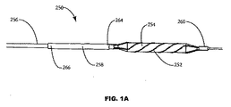
ここで図1Aおよび図1Bを参照すると、軸方向に膨張性の取り付け構造258を有する血管形成カテーテル250が示される。インターフェース構造252は、膨張可能なシェル(代表的には、膨張バルーン254)を覆って保持され、カテーテル本体256の遠位端260の一端に固定される。インターフェース構造252の近位端262は、取り付け構造258の遠位端264に連結される。取り付け構造258の近位端266は、カテーテル本体256に固定される。以下に記載されるように、取り付け構造258は、バルーン254の膨張および収縮の間に、外面構造252およびカテーテル本体256に加えられる力を低減するように構成され得る。
(Detailed description of the invention)
Referring now to FIGS. 1A and 1B, an
インターフェース構造252は、3つの別々のらせん状インターフェースエレメントとして示され、代表的にはニチノールまたは他の超弾性材料から構成される。これは現在好ましい形状であるが、インターフェースエレメントの数は、1〜10またはそれより多くに異なり得る。さらに、らせん状の形状が好ましいが、これは必須ではなく、インターフェースエレメントは、直線、曲線、ジグザグであり得るか、またはその中のバルーンの膨張を可能にする種々の他の構成のうちの任意の1つを有し得る。しかし、このらせん構造は、バルーンがステントまたは他の補綴を膨張させるのに使用される際および/またはバルーンがその後の膨張を可能にするためにステント構造のセルを通過する際に、エレメントがステント構造を妨害するリスクを減少させるので、らせん構造が一般的に好ましい。
The
取り付け構造258は、代表的に、弾性材料で作製された円柱状のオーバーチューブ(over−tube)(柔軟チューブ(compliant tube))を備える。オーバーチューブ258は、一般的に、カテーテル本体256の外径よりもわずかに大きい内径を有する。取り付け構造258の近位端の小さなセクションのみがカテーテル本体に固定されるため、インターフェース構造252に取り付けられる遠位端264は自由に浮いており、カテーテル本体256に対して自由に軸方向および旋回性にスライドする。取り付け構造252は、カテーテル本体256および外部構造252に直接固定(例えば、接着によって)されていてもよいし、縁または他の中間取り付け手段に固定されてもよい。
The mounting
バルーン254が膨張する際に、インターフェース構造252は周辺に広がり、カテーテル本体256に沿って軸方向に収縮し、取り付け構造258の上の矢印Aの向きに軸方向の力を生み出す。カテーテルの端部266においてカテーテルに固定された取り付け構造258は軸方向に伸び、インターフェース構造252の軸方向の移動に適応する。インターフェース構造252はまた、カテーテル本体256の周りを回転する傾向があり、ねじれの力Tを生じる。取り付け構造258の遠位端264は、切り目を付ける構造252の動きの全範囲を回転し、ねじれの力Tに適応する。一方近位端266は、カテーテル本体256に対して静止したままである。
As the
図1Aおよび図1Bに図示した構成により、膨張可能なシステムの柔軟性(compliance)が制御されることが可能になる。一般的に、切り目を付ける構造の一端が自由である場合には、膨張可能なシステムの柔軟性は、バルーンの柔軟性と切り目を付ける構造との組み合わせである。しかし、図1Aおよび図1Bに示される膨張可能なシステムの端部は遠位端260および近位端266に固定されているので、上記取り付け構造がその膨張可能なシステムの柔軟性を制御する。
The configuration illustrated in FIGS. 1A and 1B allows the compliance of the inflatable system to be controlled. In general, if one end of the scoring structure is free, the flexibility of the inflatable system is a combination of the flexibility of the balloon and the scoring structure. However, because the end of the inflatable system shown in FIGS. 1A and 1B is secured to the
上記システムの柔軟性は、オーバーチューブ258の材料選択、壁厚、または長さの任意の組み合わせによって異なり得る。オーバーチューブ258は、任意のエラストマー(例えば、Nylon、PebaxまたはPETのような弾性ポリマー)を含み得る。代表的に、柔軟チューブ258は、押し出し加工された管材から形成されるが、編み組まれたポリマーもしくは金属繊維、またはワイヤーメッシュもまた含み得る。ニチノールまたはステンレス鋼のような超弾性金属もまた、使用され得る。柔軟チューブが押し出し加工されたポリマーチューブである場合、壁厚は上述の範囲内で異なり得、そのチューブの長さは1cm〜10cmの範囲であり得る。いくつかの金属については、壁が薄くなり、チューブが長くなるにつれて、システムはより柔軟になる。
The flexibility of the system may vary depending on any combination of
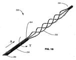
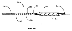
図2A〜図2Cを参照すると、柔軟チューブ258の軸方向および旋回性の柔軟性は、その柔軟チューブ258に1つ以上の穿孔を形成することによってもまた、異なり得る。この穿孔は、チューブの外周に1つ以上のスロットを備え得る。このスロットは、柔軟チューブ258の長さをらせん状に横切る1つの連続的なスロットからなってもよいし、任意の数のパターン(例えば、らせん状312または放射状314)で並んだ多数のスロットであってもよい。このスロットはまた、多数の形状(例えば、円形または長方形)であり得、目立たない長さを有してもよいし、柔軟チューブの表面を連続的に横切るものであってもよい。
With reference to FIGS. 2A-2C, the axial and pivotal flexibility of a
図3を参照すると、柔軟チューブ258の外径は、切り目を付けるカテーテル320の送達および管腔内の処置部位からの切り目を付けるカテーテル320の回収を容易にするために、テーパー状であり得る。一般的に、外径は、柔軟チューブの258の遠位端264においてより大きい。遠位端における外径D1は、つぶれるときの切り目を付ける構造およびバルーンの性質に依存して異なるが、代表的には、近位端の外径D2よりも0.004インチ〜0.01インチ大きい範囲である。近位端の外径D2は、一般的に、カテーテルの外径にできるだけ近く、柔軟チューブとカテーテルとの間の滑らかな変わり目を生み出す。例えば、0.033インチの外径を有するカテーテル本体については、遠位端の外径D1は0.042インチ、内径は0.038インチであり得、この内径はカテーテル本体間のゆとりを提供し、その結果柔軟チューブの遠位端はカテーテル本体に対して移動し得る。対応して、近位端の外径D2は0.0345インチ、内径は0.034インチにテーパー状に小さくなり得、接着によってカテーテル本体に向かって曲がるのに十分なゆとりを有する外径を有するカテーテル本体と、密に合致する。
Referring to FIG. 3, the outer diameter of the
このテーパーは、柔軟チューブの全長にわたってもよいし、あるいはその柔軟チューブの一部においてのみテーパー状であってもよい。テーパー状の柔軟チューブ258は、その切り目を付ける構造とカテーテル本体との間の変わり目を滑らかにし、そしてカテーテルの送達および回収の間の管腔壁の一部において外側のチューブまたは切り目をつける構造がこすれたりまたは傷つける可能性を最小限にする。
The taper may extend over the entire length of the flexible tube or may be tapered only on a portion of the flexible tube. Tapered
ここで図4を参照すると、マニピュレーター360を有するステント操作カテーテル350の代替的な実施形態が示される。取り付け構造258は、その遠位端264において、切り目をつける構造252に連結される。カテーテル本体256に直接固定される代わりに、近位端266はマニピュレーター360に取り付けられる。代表的には、マニピュレーター360は、カテーテル本体256の近位端に位置決めされ、取り付け構造258がカテーテル本体の長さを横切ってインターフェース構造から延びる。上述の実施形態のように、取り付け構造は、軸方向および旋回性で延びることができ、シェルが膨張する際のインターフェース構造の短縮に適応する。
Referring now to FIG. 4, an alternative embodiment of a
いくつかの実施形態において、インターフェース構造252およびバルーン254の柔軟性は、放射状に膨張可能なシェルの膨張または収縮の間にマニピュレーターを作動させることにより制御される。1つの局面において、取り付け構造258は、バルーンがふくらむかまたはしぼむ際に、カテーテル本体256に対して軸方向に進み得る。例えば、取り付け構造258は、カテーテル本体256の遠位端から引き離され得、一方でバルーン254は膨張され柔軟なバルーンを制限する。取り付け構造258はまた、バルーン254がしぼまされてそのバルーンおよび切り目を付ける構造の外形を最小にする間かまたはその後に、カテーテル本体256の遠位端から引き抜かれ得る。あるいは、マニピュレーター360は、カテーテル本体256に対して取り付け構造258を回転させるのに使用され得、つぶれている状態から膨張している状態に移る間およびつぶれた状態に戻る間のバルーンおよび切り目を付ける構造の柔軟性を制御する。
In some embodiments, the flexibility of the
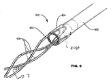
ここで図5および図6を参照すると、二層積層の柔軟チューブ402を有するインターフェースケージ構造400が図示される。図6に示されるように、柔軟チューブ402は、少なくともその遠位端410に積層構造404を有する。この積層構造は、図6における破線によって示されるように、インターフェースエレメント406の近位端408を保持する。このインターフェースエレメント406は、図6に示されるように、柔軟チューブの外面を覆ってあてはまるようなサイズであり得、積層がそのエレメントを覆っている。あるいは、柔軟なスリーブチューブ402は、インターフェース構造406の内面にあてはまるようなサイズであり得、エレメント406のまわりに積層が形成される(図示せず)。
Referring now to FIGS. 5 and 6, an
積層構造は、柔軟チューブ402に類似のポリマーから構成され得、熱によって縮むかまたは融解して、柔軟なスリーブを柔軟チューブに熱的に接着させ、インターフェースエレメント406をはさみこむ。あるいは、接着剤または他の接着法(例えば、超音波またはRFエネルギー)が、構造を積層させるために使用され得る。図5および図6に示されるような積層構造は、滑らかな変わり目、および切り目を付けるケージと取り付け構造との間の増強された接着を提供する。そのような滑らかな変わり目は、その切り目をつけるケージを血管系から取り除くときに、特に有利である。
The laminated structure may be composed of a polymer similar to the
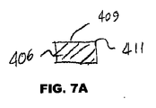
インターフェースエレメント406は、一般的に正方形または長方形の断面を有するように示されている。例えば、エレメント406は、図7に示されるような長方形の断面を有する。この断面は、ケージが中で膨張する際にステントまたは他の補綴に係合する領域である平坦な頂部を備える。しかし、この断面は、比較的鋭い角411を有する。そのような鋭い角は、ケージが中で膨張するときにステントを損傷するリスクを提示している。したがって、図5Bに図示されるような、平坦な表面409が丸い角413の間に位置するようなインターフェースエレメント406を使用することが、しばしば好ましい。ステントに力を均等に分配するために平坦な表面409が一般的には好ましいが、当然、均等な力を送達させながら、その表面にわずかな曲げまたは冠を提供することも可能である。しかし、膨張の際にプラークに切り目を入れることが意図される「カッティングバルーン」および他の血管形成デバイスにおける使用が一般的に望ましいような、集中した力を与える構造を採用することは、一般的に望ましくない。
図8および図9は、膨張可能な膨張バルーンのまわりに位置されるインターフェースケージ400を図示する。図9に示されるように、インターフェースケージの遠位端418は、末端キャップ416によってカテーテル本体の遠位先端414と連結され得る。この末端キャップ416は、適合性のポリマーから構成され得、カテーテル本体に熱的に接着され得、インターフェース構造の遠位端418をカテーテル本体に固定し得る。
8 and 9 illustrate the
ここで図10〜12を参照すると、膨張可能なインターフェースケージ406をバルーンカテーテル上に取り付けるための方法が図示されている。インターフェースケージ406は、バルーン412の外径よりもわずかに長い内径を有する挿入チューブを覆って装着することによって、予め膨らんでいる。バルーン412を有するカテーテル本体420が次いで、挿入チューブ422の内径の中に挿入され、図11に図示されるようにバルーン412がインターフェース構造406に対して適切に位置決めされるまで差し込まれる。挿入チューブ422は次いで、引き戻され、膨らんだ切り目を付ける構造が図12に示されるようにバルーン412およびカテーテル本体420のまわりにつぶれるのを可能にする。インターフェース構造406は次いで、その遠位端418において、カテーテル本体420の遠位先端414に固定され、インターフェース構造/取り付け構造アセンブリがカテーテル本体420の内側の位置に固定される。
With reference now to FIGS. 10-12, a method for mounting an
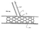
ここで図13A〜図13Dを参照すると、セルCおよびステントSの内側の外周を拡張するためのバルーンカテーテル500の使用が開示される。ステントSは、二分岐を形成する分枝した血管Vを有する主要な血管MV内に位置している。このカテーテル500は、膨張可能なバルーン512または他のシェル構造のまわりにインターフェース構造510を保有している。このカテーテルは、代表的にはガイドワイヤーGWにより、主要な血管MVの管腔およびセルCの内部を通って導かれる。インターフェース構造510は、代表的には、手順の間に蛍光透視によって位置を見ることによって、その構造がそのセル内の中心になるように位置決めされる。一旦、インターフェース構造510が適切に位置決めされると、バルーン512が図13Cに示されるように膨張される。適切な膨張力(代表的には、4気圧〜20気圧の範囲の圧力)を加えることにより、図13Dに示されるようにこのセルは均等に膨張され得る。
Referring now to FIGS. 13A-13D, the use of a
ここで図14Aおよび図14Bを参照すると、インターフェース構造510を使用する利点が記載される。図14Aに示されるように、インターフェース構造を有さない従来の血管形成バルーンの使用は、一般的に、セルCの周囲の異なる点に不均等な膨張力をもたらす。特に、このバルーンがセルのより大きい長さと接触することができる場合は、より大きな力が加えられる。対照的に、インターフェース構造510の個々のエレメント514の使用は、セルCの周囲に接触する点において、非常に均等な膨張を提供する。別の利点は、バルーンがステントセル内で引っかかるのをケージが防ぎ、それによって従来のバルーンの使用では起こり得る突然の開口を回避することができ、そしてステントセルのより均等かつ制御された膨張を生み出すことができることである。そのような制御された線形の膨張は、ステント支柱に、そして結果的にバルーンおよび血管に、損傷を非常に引き起こしにくい。
Referring now to FIGS. 14A and 14B, the advantages of using the
ここで図15Aおよび図15Bを参照すると、本発明の別の実施形態において、カテーテル500は、ステントSまたは他の血管補綴を保有する。ステントSは、代表的に、インターフェース構造510(これは代表的にはらせんユニットである)を覆って圧着されている。この様式において、インターフェース構造510は、病変Lの硬い領域に対してステステントを押すことができ、図15Bに示すように、硬いかまたは石灰化した病変においてさえ、そして事前膨張なしでさえ、血管壁に対してステントの適切な位置決めを可能にする。
Referring now to FIGS. 15A and 15B, in another embodiment of the present invention, the
ステントを送達するためのインターフェース構造を有するバルーンまたは他の膨張可能なシェルの使用は、ステントから周囲の血管壁へより大きな力の病変への伝達を可能にし、硬い病変においてでもステントのよりよい壁押圧(wall apposition)を強化する。多くの場合において、ステントは、不均等な石灰化を有する病変において、すぐれた壁押圧を有さない。これらの病変において、バルーンは、石灰化したセグメントに屈し、ステントはそのようなセグメントを完全には分散させない。本発明のインターフェース表面を使用することにより、バルーンまたは他の膨張可能なシェルは、外向きの力を均等に分配し、膨張の間ステントを支持し、石灰化したセグメントにおいてでさえ完全な膨張を可能にする。この利点は、個々のセルがより低い放射状の力を有する薄い壁ステントにおいてより重要である。なぜなら、その支柱は従来のステントと比較して非常に薄いからである。本発明のインターフェース構造の使用は、少なくともいくつかの場合には、事前膨張の必要性を低減するかまたは排除する。 The use of a balloon or other inflatable shell with an interface structure to deliver the stent allows transmission of greater force to the lesion from the stent to the surrounding vessel wall, and the better wall of the stent even in hard lesions Strengthen the wall application. In many cases, stents do not have excellent wall pressing in lesions with uneven calcification. In these lesions, the balloon bows to calcified segments and the stent does not completely disperse such segments. By using the interface surface of the present invention, the balloon or other inflatable shell distributes the outward force evenly, supports the stent during expansion, and provides full expansion even in calcified segments. enable. This advantage is more important in thin wall stents where individual cells have lower radial forces. This is because the struts are very thin compared to conventional stents. The use of the interface structure of the present invention reduces or eliminates the need for pre-inflation in at least some cases.
さらに、ステントが配置された後にバルーンがしぼむときに、インターフェース構造は、バルーンが「飛ぶ」のを防ぐ助けをする内向きの放射状の力を加えることによって、バルーンがしぼむ助けをする。飛ぶことは、バルーンがしぼんで平坦な形状になるときに起こる。この平坦なバルーンは、ある軸において非常に狭いが、他の軸において管よりも広い。したがって、バルーンは、ステント支柱によって捕らえられるか、または管の壁にむかってこすられる傾向を有し、このことがバルーンの回収を困難にしている。最悪の場合は、ステントによるバルーンの捕捉は、手順の失敗を引き起こすこともあり、インターフェース表面による強化は、取り外しがより容易である小さい形状のしぼんだバルーンをもたらすことができる。 In addition, when the balloon is deflated after the stent is deployed, the interface structure helps the balloon deflate by applying an inward radial force that helps prevent the balloon from “flying”. Flying occurs when the balloon is deflated into a flat shape. This flat balloon is very narrow in one axis but wider than the tube in the other axis. Thus, the balloon tends to be captured by the stent struts or rubbed against the wall of the tube, which makes it difficult to retrieve the balloon. In the worst case, capture of the balloon by the stent can cause failure of the procedure, and reinforcement by the interface surface can result in a small shaped deflated balloon that is easier to remove.
本発明は、本明細書中で具体的に示され、そして記載されたものに限定されないことが、当業者によって認識される。本発明の範囲内にある代替の実施形態も企図される。 It will be appreciated by persons skilled in the art that the present invention is not limited to what has been particularly shown and described herein. Alternative embodiments within the scope of the present invention are also contemplated.
Claims (25)
該補綴内のセルを通して膨張性のシェルを位置決めする工程であって、インターフェース構造が該膨張性のシェルを囲んでいる、工程;および
該シェルを膨張させて、該セル内の該構造を膨張させ、該セルを開けて該通路を形成する、工程、
を包含する、方法。 A method for opening a passageway in a branched blood vessel through a prosthesis in a main blood vessel, the method comprising:
Positioning an inflatable shell through a cell in the prosthesis, wherein an interface structure surrounds the inflatable shell; and inflating the shell to inflate the structure in the cell Opening the cell to form the passage,
Including the method.
該補綴を該硬化したプラークの領域に送達する工程;および
膨張を引き起こすように該補綴内でシェルを膨張させる工程であって、該シェルはインターフェース構造内に配置され、該インターフェース構造は、該補綴が膨張する際に該補綴の内面と係合する、工程、
を包含する、方法。 A method for inflating a vascular prosthesis within an area of a cured plaque, the method comprising:
Delivering the prosthesis to an area of the hardened plaque; and inflating a shell within the prosthesis to cause expansion, the shell being disposed within an interface structure, the interface structure comprising the prosthesis Engaging the inner surface of the prosthesis as it expands;
Including the method.
近位端および遠位端を有する、カテーテル本体;
該カテーテル本体の遠位端に近い、らせん状に膨張性のシェル;および
該らせん状に膨張性のシェルに外接しているが取り付けられていない、ステントインターフェース構造、
を備える、カテーテル。 A stent manipulation catheter comprising:
A catheter body having a proximal end and a distal end;
A helically inflatable shell near the distal end of the catheter body; and a stent interface structure circumscribing but not attached to the helically inflatable shell;
A catheter.
Applications Claiming Priority (2)
| Application Number | Priority Date | Filing Date | Title |
|---|---|---|---|
| US10/917,902 US20050021070A1 (en) | 2003-01-21 | 2004-08-13 | Methods and apparatus for manipulating vascular prostheses |
| PCT/US2005/028809 WO2006020905A2 (en) | 2004-08-13 | 2005-08-10 | Methods and apparatus for manipulating vascular prostheses |
Publications (2)
| Publication Number | Publication Date |
|---|---|
| JP2008509749A true JP2008509749A (en) | 2008-04-03 |
| JP2008509749A5 JP2008509749A5 (en) | 2008-09-04 |
Family
ID=35908193
Family Applications (1)
| Application Number | Title | Priority Date | Filing Date |
|---|---|---|---|
| JP2007525841A Pending JP2008509749A (en) | 2004-08-13 | 2005-08-10 | Method and apparatus for manipulating a vascular prosthesis |
Country Status (4)
| Country | Link |
|---|---|
| US (1) | US20050021070A1 (en) |
| EP (1) | EP1781211A4 (en) |
| JP (1) | JP2008509749A (en) |
| WO (1) | WO2006020905A2 (en) |
Cited By (1)
| Publication number | Priority date | Publication date | Assignee | Title |
|---|---|---|---|---|
| US11697004B2 (en) | 2015-05-15 | 2023-07-11 | Nipro Corporation | Method of manufacturing a balloon catheter |
Families Citing this family (42)
| Publication number | Priority date | Publication date | Assignee | Title |
|---|---|---|---|---|
| US7691119B2 (en) | 2001-11-09 | 2010-04-06 | Angioscore, Inc. | Balloon catheter with non-deployable stent |
| US20040111108A1 (en) | 2001-11-09 | 2004-06-10 | Farnan Robert C. | Balloon catheter with non-deployable stent |
| US8080026B2 (en) | 2003-01-21 | 2011-12-20 | Angioscore, Inc. | Apparatus and methods for treating hardened vascular lesions |
| US7686824B2 (en) * | 2003-01-21 | 2010-03-30 | Angioscore, Inc. | Apparatus and methods for treating hardened vascular lesions |
| US20060178685A1 (en) * | 2004-12-30 | 2006-08-10 | Cook Incorporated | Balloon expandable plaque cutting device |
| DE602005010906D1 (en) * | 2004-12-30 | 2008-12-18 | Cook Inc | CATHETER ASSEMBLY WITH PLAQUE CUTTING BALLOON |
| US10076641B2 (en) | 2005-05-11 | 2018-09-18 | The Spectranetics Corporation | Methods and systems for delivering substances into luminal walls |
| US8672990B2 (en) * | 2005-05-27 | 2014-03-18 | Boston Scientific Scimed, Inc. | Fiber mesh controlled expansion balloon catheter |
| US7708753B2 (en) | 2005-09-27 | 2010-05-04 | Cook Incorporated | Balloon catheter with extendable dilation wire |
| US20080228139A1 (en) * | 2007-02-06 | 2008-09-18 | Cook Incorporated | Angioplasty Balloon With Concealed Wires |
| US8323307B2 (en) * | 2007-02-13 | 2012-12-04 | Cook Medical Technologies Llc | Balloon catheter with dilating elements |
| US20080300610A1 (en) | 2007-05-31 | 2008-12-04 | Cook Incorporated | Device for treating hardened lesions and method of use thereof |
| US20090171283A1 (en) * | 2007-12-27 | 2009-07-02 | Cook Incorporated | Method of bonding a dilation element to a surface of an angioplasty balloon |
| US20090171284A1 (en) * | 2007-12-27 | 2009-07-02 | Cook Incorporated | Dilation system |
| US8192675B2 (en) | 2008-03-13 | 2012-06-05 | Cook Medical Technologies Llc | Cutting balloon with connector and dilation element |
| US11229777B2 (en) | 2008-03-21 | 2022-01-25 | Cagent Vascular, Inc. | System and method for plaque serration |
| JP5846905B2 (en) | 2008-03-21 | 2016-01-20 | ケイジェント ヴァスキュラー, エルエルシーCagent Vascular, Llc | Intravascular device for perforation and serration of atherosclerotic plaques in blood vessels |
| US9480826B2 (en) | 2008-03-21 | 2016-11-01 | Cagent Vascular, Llc | Intravascular device |
| US20100010521A1 (en) * | 2008-07-10 | 2010-01-14 | Cook Incorporated | Cutting balloon with movable member |
| EP2172242A1 (en) * | 2008-10-03 | 2010-04-07 | National University of Ireland Galway | Intravascular Treatment Device |
| US20100286593A1 (en) * | 2009-05-11 | 2010-11-11 | Hotspur Technologies, Inc. | Balloon catheter with cutting features and methods for use |
| US8348987B2 (en) * | 2009-12-22 | 2013-01-08 | Cook Medical Technologies Llc | Balloon with scoring member |
| EP2380604A1 (en) | 2010-04-19 | 2011-10-26 | InnoRa Gmbh | Improved coating formulations for scoring or cutting balloon catheters |
| US8632559B2 (en) | 2010-09-21 | 2014-01-21 | Angioscore, Inc. | Method and system for treating valve stenosis |
| AT511788A1 (en) * | 2011-07-29 | 2013-02-15 | Georg Dr Gaul | DEVICE FOR THE SPECIFIC ARRANGEMENT OF A STENT |
| US9808276B2 (en) * | 2013-04-25 | 2017-11-07 | Invatec S.P.A. | Angioplasty balloon having selectively deployable cutting or scoring element and related methods |
| US10117668B2 (en) | 2013-10-08 | 2018-11-06 | The Spectranetics Corporation | Balloon catheter with non-deployable stent having improved stability |
| US9149612B2 (en) | 2013-11-13 | 2015-10-06 | West Coast Catheter, Inc. | Flexible high-pressure balloons |
| US9782571B2 (en) | 2014-01-30 | 2017-10-10 | Chuter A. M. Timothy | Flexible high-pressure angioplasty balloons |
| US10201685B2 (en) | 2013-11-13 | 2019-02-12 | West Coast Catheter, Inc. | High-pressure balloons |
| US10286190B2 (en) | 2013-12-11 | 2019-05-14 | Cook Medical Technologies Llc | Balloon catheter with dynamic vessel engaging member |
| US9956384B2 (en) | 2014-01-24 | 2018-05-01 | Cook Medical Technologies Llc | Articulating balloon catheter and method for using the same |
| US10463842B2 (en) * | 2014-06-04 | 2019-11-05 | Cagent Vascular, Llc | Cage for medical balloon |
| US10471238B2 (en) | 2014-11-03 | 2019-11-12 | Cagent Vascular, Llc | Serration balloon |
| WO2017049227A2 (en) | 2015-09-17 | 2017-03-23 | Cagent Vascular, Llc | Wedge dissectors for a medical ballon |
| WO2017127527A1 (en) * | 2016-01-20 | 2017-07-27 | Veniti, Inc. | Medical balloon with reinforcement structure |
| US10492937B2 (en) * | 2016-10-17 | 2019-12-03 | Cook Medical Technologies Llc | Deploying a balloon expandable stent to induce spiral flow |
| CA3044046A1 (en) | 2016-11-16 | 2018-05-24 | Cagent Vascular, Llc | Systems and methods of depositing drug into tissue through serrations |
| JP7235763B2 (en) * | 2018-03-09 | 2023-03-08 | シー・アール・バード・インコーポレーテッド | Inflatable medical balloon containing continuous fibers |
| EP3801306B1 (en) * | 2018-06-08 | 2024-01-10 | SurModics, Inc. | Scoring devices and catheter systems for controlled vessel lesion dissection |
| WO2020023749A1 (en) | 2018-07-25 | 2020-01-30 | Cagent Vascular, Llc | Medical balloon catheters with enhanced pushability |
| IN202021018863A (en) * | 2020-05-03 | 2020-06-05 | Meril Life Sciences Pvt. Ltd. |
Citations (4)
| Publication number | Priority date | Publication date | Assignee | Title |
|---|---|---|---|---|
| JPH10502273A (en) * | 1994-06-30 | 1998-03-03 | ボストン サイエンティフィック コーポレイション | Stent and therapeutic delivery system |
| JP2002126086A (en) * | 2000-07-04 | 2002-05-08 | Transgene Sa | Device for dosing composition to human or animal somatic canal |
| JP2004148013A (en) * | 2002-10-31 | 2004-05-27 | Kanegafuchi Chem Ind Co Ltd | Balloon, and balloon catheter |
| WO2004060460A2 (en) * | 2003-01-02 | 2004-07-22 | Boston Scientific Limited | Medical devices with cutting element. |
Family Cites Families (100)
| Publication number | Priority date | Publication date | Assignee | Title |
|---|---|---|---|---|
| US4838853A (en) * | 1987-02-05 | 1989-06-13 | Interventional Technologies Inc. | Apparatus for trimming meniscus |
| US4942788A (en) * | 1987-11-23 | 1990-07-24 | Interventional Technologies, Inc. | Method of manufacturing a cutter for atherectomy device |
| US4895166A (en) * | 1987-11-23 | 1990-01-23 | Interventional Technologies, Inc. | Rotatable cutter for the lumen of a blood vesel |
| FR2624747A1 (en) * | 1987-12-18 | 1989-06-23 | Delsanti Gerard | REMOVABLE ENDO-ARTERIAL DEVICES FOR REPAIRING ARTERIAL WALL DECOLLEMENTS |
| US4921484A (en) * | 1988-07-25 | 1990-05-01 | Cordis Corporation | Mesh balloon catheter device |
| US5779698A (en) * | 1989-01-18 | 1998-07-14 | Applied Medical Resources Corporation | Angioplasty catheter system and method for making same |
| US4986807A (en) * | 1989-01-23 | 1991-01-22 | Interventional Technologies, Inc. | Atherectomy cutter with radially projecting blade |
| US4950277A (en) * | 1989-01-23 | 1990-08-21 | Interventional Technologies, Inc. | Atherectomy cutting device with eccentric wire and method |
| US5116318A (en) * | 1989-06-06 | 1992-05-26 | Cordis Corporation | Dilatation balloon within an elastic sleeve |
| US5019088A (en) * | 1989-11-07 | 1991-05-28 | Interventional Technologies Inc. | Ovoid atherectomy cutter |
| US5026384A (en) * | 1989-11-07 | 1991-06-25 | Interventional Technologies, Inc. | Atherectomy systems and methods |
| US5019089A (en) * | 1989-12-07 | 1991-05-28 | Interventional Technologies Inc. | Atherectomy advancing probe and method of use |
| US5003918A (en) * | 1989-12-28 | 1991-04-02 | Interventional Technologies, Inc. | Apparatus for manufacturing atherectomy torque tubes |
| US5108416A (en) * | 1990-02-13 | 1992-04-28 | C. R. Bard, Inc. | Stent introducer system |
| US5221261A (en) * | 1990-04-12 | 1993-06-22 | Schneider (Usa) Inc. | Radially expandable fixation member |
| US5320634A (en) * | 1990-07-03 | 1994-06-14 | Interventional Technologies, Inc. | Balloon catheter with seated cutting edges |
| US5196024A (en) * | 1990-07-03 | 1993-03-23 | Cedars-Sinai Medical Center | Balloon catheter with cutting edge |
| US5101682A (en) * | 1990-07-06 | 1992-04-07 | Interventional Technologies, Inc. | Reinforced tubing |
| US5098440A (en) * | 1990-08-14 | 1992-03-24 | Cordis Corporation | Object retrieval method and apparatus |
| US5100423A (en) * | 1990-08-21 | 1992-03-31 | Medical Engineering & Development Institute, Inc. | Ablation catheter |
| US5350101A (en) * | 1990-11-20 | 1994-09-27 | Interventional Technologies Inc. | Device for advancing a rotatable tube |
| US5112345A (en) * | 1990-12-17 | 1992-05-12 | Interventional Technologies | Atherectomy cutter with arcuate blades |
| US5217474A (en) * | 1991-07-15 | 1993-06-08 | Zacca Nadim M | Expandable tip atherectomy method and apparatus |
| EP0549100A1 (en) * | 1991-12-20 | 1993-06-30 | Interventional Technologies Inc | Catheter balloon formed from a polymeric composite |
| US5192291A (en) * | 1992-01-13 | 1993-03-09 | Interventional Technologies, Inc. | Rotationally expandable atherectomy cutter assembly |
| US5742019A (en) * | 1992-01-13 | 1998-04-21 | Interventional Technologies Inc. | Method for manufacturing an atherectomy cutter having a positive angle of attack |
| US5224945A (en) * | 1992-01-13 | 1993-07-06 | Interventional Technologies, Inc. | Compressible/expandable atherectomy cutter |
| US5224949A (en) * | 1992-01-13 | 1993-07-06 | Interventional Technologies, Inc. | Camming device |
| US5209727A (en) * | 1992-01-29 | 1993-05-11 | Interventional Technologies, Inc. | Guide wire with integral angioplasty balloon |
| US5226887A (en) * | 1992-02-07 | 1993-07-13 | Interventional Technologies, Inc. | Collapsible folding angioplasty balloon |
| US5295493A (en) * | 1992-03-19 | 1994-03-22 | Interventional Technologies, Inc. | Anatomical guide wire |
| US5176693A (en) * | 1992-05-11 | 1993-01-05 | Interventional Technologies, Inc. | Balloon expandable atherectomy cutter |
| US5243997A (en) * | 1992-09-14 | 1993-09-14 | Interventional Technologies, Inc. | Vibrating device for a guide wire |
| US5524635A (en) * | 1992-09-14 | 1996-06-11 | Interventional Technologies Inc. | Apparatus for advancing a guide wire |
| US5443078A (en) * | 1992-09-14 | 1995-08-22 | Interventional Technologies, Inc. | Method for advancing a guide wire |
| US5318576A (en) * | 1992-12-16 | 1994-06-07 | Plassche Jr Walter M | Endovascular surgery systems |
| CA2118886C (en) * | 1993-05-07 | 1998-12-08 | Dennis Vigil | Method and apparatus for dilatation of a stenotic vessel |
| US5545132A (en) * | 1993-12-21 | 1996-08-13 | C. R. Bard, Inc. | Helically grooved balloon for dilatation catheter and method of using |
| US6245040B1 (en) * | 1994-01-14 | 2001-06-12 | Cordis Corporation | Perfusion balloon brace and method of use |
| US5891090A (en) * | 1994-03-14 | 1999-04-06 | Advanced Cardiovascular Systems, Inc. | Perfusion dilatation catheter with expanded support coil |
| DE69515246T2 (en) * | 1994-10-20 | 2000-09-07 | Interventional Technologies | Process for the production of a polymer material with improved mechanical properties |
| CA2157697C (en) * | 1995-01-10 | 2007-03-13 | Banning Gray Lary | Vascular incisor/dilator |
| NL9500468A (en) * | 1995-03-08 | 1996-10-01 | Cordis Europ | Balloon catheter and method of making it. |
| US5624433A (en) * | 1995-04-24 | 1997-04-29 | Interventional Technologies Inc. | Angioplasty balloon with light incisor |
| US5556408A (en) * | 1995-04-27 | 1996-09-17 | Interventional Technologies Inc. | Expandable and compressible atherectomy cutter |
| US6602281B1 (en) * | 1995-06-05 | 2003-08-05 | Avantec Vascular Corporation | Radially expansible vessel scaffold having beams and expansion joints |
| US5746716A (en) * | 1995-07-10 | 1998-05-05 | Interventional Technologies Inc. | Catheter for injecting fluid medication into an arterial wall |
| US5873852A (en) * | 1995-07-10 | 1999-02-23 | Interventional Technologies | Device for injecting fluid into a wall of a blood vessel |
| US6102904A (en) * | 1995-07-10 | 2000-08-15 | Interventional Technologies, Inc. | Device for injecting fluid into a wall of a blood vessel |
| US5713863A (en) * | 1996-01-11 | 1998-02-03 | Interventional Technologies Inc. | Catheter with fluid medication injectors |
| US5556405A (en) * | 1995-10-13 | 1996-09-17 | Interventional Technologies Inc. | Universal dilator with reciprocal incisor |
| US5749848A (en) * | 1995-11-13 | 1998-05-12 | Cardiovascular Imaging Systems, Inc. | Catheter system having imaging, balloon angioplasty, and stent deployment capabilities, and method of use for guided stent deployment |
| US5690642A (en) * | 1996-01-18 | 1997-11-25 | Cook Incorporated | Rapid exchange stent delivery balloon catheter |
| US6071285A (en) * | 1996-03-25 | 2000-06-06 | Lashinski; Robert D. | Rapid exchange folded balloon catheter and stent delivery system |
| US5735816A (en) * | 1996-07-23 | 1998-04-07 | Medtronic, Inc. | Spiral sheath retainer for autoperfusion dilatation catheter balloon |
| CA2213015A1 (en) * | 1996-08-23 | 1998-02-23 | Arterial Vascular Engineering, Inc. | A profiled stent and method of manufacture |
| CA2209366C (en) * | 1996-09-13 | 2004-11-02 | Interventional Technologies, Inc. | Incisor-dilator with tapered balloon |
| US5797935A (en) * | 1996-09-26 | 1998-08-25 | Interventional Technologies Inc. | Balloon activated forced concentrators for incising stenotic segments |
| US6117153A (en) * | 1996-10-03 | 2000-09-12 | Interventional Technologies, Inc. | Neovascularization catheter |
| US5800450A (en) * | 1996-10-03 | 1998-09-01 | Interventional Technologies Inc. | Neovascularization catheter |
| US5755778A (en) * | 1996-10-16 | 1998-05-26 | Nitinol Medical Technologies, Inc. | Anastomosis device |
| US5879342A (en) * | 1996-10-21 | 1999-03-09 | Kelley; Gregory S. | Flexible and reinforced tubing |
| US6835203B1 (en) * | 1996-11-04 | 2004-12-28 | Advanced Stent Technologies, Inc. | Extendible stent apparatus |
| US5713913A (en) * | 1996-11-12 | 1998-02-03 | Interventional Technologies Inc. | Device and method for transecting a coronary artery |
| US5916166A (en) * | 1996-11-19 | 1999-06-29 | Interventional Technologies, Inc. | Medical guidewire with fully hardened core |
| US5827321A (en) * | 1997-02-07 | 1998-10-27 | Cornerstone Devices, Inc. | Non-Foreshortening intraluminal prosthesis |
| US6071286A (en) * | 1997-02-19 | 2000-06-06 | Mawad; Michel E. | Combination angioplasty balloon/stent deployment device |
| US5902475A (en) * | 1997-04-08 | 1999-05-11 | Interventional Technologies, Inc. | Method for manufacturing a stent |
| US5868779A (en) * | 1997-08-15 | 1999-02-09 | Ruiz; Carlos E. | Apparatus and methods for dilating vessels and hollow-body organs |
| AU1190699A (en) * | 1997-10-20 | 1999-05-10 | Robert D. Bersin | Helical spiral balloon catheter |
| US6450989B2 (en) * | 1998-04-27 | 2002-09-17 | Artemis Medical, Inc. | Dilating and support apparatus with disease inhibitors and methods for use |
| US6780199B2 (en) * | 1998-05-15 | 2004-08-24 | Advanced Cardiovascular Systems, Inc. | Enhanced stent delivery system |
| CA2330134A1 (en) * | 1998-05-15 | 1999-11-25 | Medgination, Inc. | Enhanced balloon dilatation system |
| US6447501B1 (en) * | 1998-05-15 | 2002-09-10 | X Technologies Inc. | Enhanced stent delivery system |
| US6117104A (en) * | 1998-09-08 | 2000-09-12 | Advanced Cardiovascular Systems, Inc. | Stent deployment system and method of use |
| US6053913A (en) * | 1998-09-10 | 2000-04-25 | Tu; Lily Chen | Rapid exchange stented balloon catheter having ablation capabilities |
| US6036689A (en) * | 1998-09-24 | 2000-03-14 | Tu; Lily Chen | Ablation device for treating atherosclerotic tissues |
| US6123718A (en) * | 1998-11-02 | 2000-09-26 | Polymerex Medical Corp. | Balloon catheter |
| US6355059B1 (en) * | 1998-12-03 | 2002-03-12 | Medinol, Ltd. | Serpentine coiled ladder stent |
| US6210392B1 (en) * | 1999-01-15 | 2001-04-03 | Interventional Technologies, Inc. | Method for treating a wall of a blood vessel |
| US6077298A (en) * | 1999-02-20 | 2000-06-20 | Tu; Lily Chen | Expandable/retractable stent and methods thereof |
| NL1012527C2 (en) * | 1999-07-06 | 2001-01-09 | Cordis Europ | Balloon catheter with tear line. |
| US6454775B1 (en) * | 1999-12-06 | 2002-09-24 | Bacchus Vascular Inc. | Systems and methods for clot disruption and retrieval |
| US6450988B1 (en) * | 1999-12-29 | 2002-09-17 | Advanced Cardiovascular Systems, Inc. | Centering catheter with improved perfusion |
| US6648912B2 (en) * | 2000-02-15 | 2003-11-18 | Eva Corporation | Temporary stent assembly for use in a surgical procedure |
| US20010031981A1 (en) * | 2000-03-31 | 2001-10-18 | Evans Michael A. | Method and device for locating guidewire and treating chronic total occlusions |
| AU7961901A (en) * | 2000-05-26 | 2001-12-03 | Wallsten Medical S.A. | Balloon catheter |
| US6569180B1 (en) * | 2000-06-02 | 2003-05-27 | Avantec Vascular Corporation | Catheter having exchangeable balloon |
| EP1305078B1 (en) * | 2000-07-24 | 2011-06-29 | Jeffrey Grayzel | Stiffened balloon catheter for dilatation and stenting |
| WO2002067653A2 (en) * | 2001-02-26 | 2002-09-06 | Scimed Life Systems, Inc. | Bifurcated stent and delivery system |
| US6425882B1 (en) * | 2001-05-01 | 2002-07-30 | Interventional Technologies Inc. | Folding spring for a catheter balloon |
| US6562062B2 (en) * | 2001-08-10 | 2003-05-13 | Scimed Life Systems, Inc. | Balloon anchoring system |
| EE200200476A (en) * | 2001-08-27 | 2003-04-15 | Medinol Ltd. | The stent system and its manufacturing method |
| US20030065381A1 (en) * | 2001-09-28 | 2003-04-03 | Solar Ronald J. | Longitudinal focussed force stent |
| US20040111108A1 (en) * | 2001-11-09 | 2004-06-10 | Farnan Robert C. | Balloon catheter with non-deployable stent |
| US20030144683A1 (en) * | 2001-12-13 | 2003-07-31 | Avantec Vascular Corporation | Inflatable members having concentrated force regions |
| US7186237B2 (en) * | 2002-02-14 | 2007-03-06 | Avantec Vascular Corporation | Ballon catheter for creating a longitudinal channel in a lesion and method |
| US7686824B2 (en) * | 2003-01-21 | 2010-03-30 | Angioscore, Inc. | Apparatus and methods for treating hardened vascular lesions |
| US7314480B2 (en) * | 2003-02-27 | 2008-01-01 | Boston Scientific Scimed, Inc. | Rotating balloon expandable sheath bifurcation delivery |
| US20060184191A1 (en) * | 2005-02-11 | 2006-08-17 | Boston Scientific Scimed, Inc. | Cutting balloon catheter having increased flexibility regions |
-
2004
- 2004-08-13 US US10/917,902 patent/US20050021070A1/en not_active Abandoned
-
2005
- 2005-08-10 WO PCT/US2005/028809 patent/WO2006020905A2/en active Application Filing
- 2005-08-10 EP EP05792875A patent/EP1781211A4/en not_active Withdrawn
- 2005-08-10 JP JP2007525841A patent/JP2008509749A/en active Pending
Patent Citations (4)
| Publication number | Priority date | Publication date | Assignee | Title |
|---|---|---|---|---|
| JPH10502273A (en) * | 1994-06-30 | 1998-03-03 | ボストン サイエンティフィック コーポレイション | Stent and therapeutic delivery system |
| JP2002126086A (en) * | 2000-07-04 | 2002-05-08 | Transgene Sa | Device for dosing composition to human or animal somatic canal |
| JP2004148013A (en) * | 2002-10-31 | 2004-05-27 | Kanegafuchi Chem Ind Co Ltd | Balloon, and balloon catheter |
| WO2004060460A2 (en) * | 2003-01-02 | 2004-07-22 | Boston Scientific Limited | Medical devices with cutting element. |
Cited By (1)
| Publication number | Priority date | Publication date | Assignee | Title |
|---|---|---|---|---|
| US11697004B2 (en) | 2015-05-15 | 2023-07-11 | Nipro Corporation | Method of manufacturing a balloon catheter |
Also Published As
| Publication number | Publication date |
|---|---|
| WO2006020905A3 (en) | 2007-09-13 |
| EP1781211A4 (en) | 2010-01-27 |
| US20050021070A1 (en) | 2005-01-27 |
| WO2006020905A2 (en) | 2006-02-23 |
| EP1781211A2 (en) | 2007-05-09 |
Similar Documents
| Publication | Publication Date | Title |
|---|---|---|
| JP2008509749A (en) | Method and apparatus for manipulating a vascular prosthesis | |
| US10722694B2 (en) | Apparatus and methods for treating hardened vascular lesions | |
| US10143824B2 (en) | Catheter assemblies and methods for stabilizing a catheter assembly within a subintimal space | |
| US7955350B2 (en) | Apparatus and methods for treating hardened vascular lesions | |
| US10485571B2 (en) | Balloon catheter with non-deployable stent having improved stability | |
| US7396358B2 (en) | Device and method for converting a balloon catheter into a cutting balloon catheter | |
| US5573509A (en) | Catheter with an expandable perfusion slit | |
| US5456667A (en) | Temporary stenting catheter with one-piece expandable segment | |
| US6632236B2 (en) | Catheter having radially expandable main body | |
| US20180028221A1 (en) | Angioplasty balloon having selectively deployable cutting or scoring element and related methods | |
| US9211394B2 (en) | Angioplasty balloon with conceal wires | |
| US20180056051A1 (en) | Apparatus and methods for treating hardened vascular lesions |
Legal Events
| Date | Code | Title | Description |
|---|---|---|---|
| A521 | Written amendment |
Free format text: JAPANESE INTERMEDIATE CODE: A523 Effective date: 20080718 |
|
| A621 | Written request for application examination |
Free format text: JAPANESE INTERMEDIATE CODE: A621 Effective date: 20080718 |
|
| A131 | Notification of reasons for refusal |
Free format text: JAPANESE INTERMEDIATE CODE: A131 Effective date: 20100722 |
|
| A601 | Written request for extension of time |
Free format text: JAPANESE INTERMEDIATE CODE: A601 Effective date: 20101021 |
|
| A602 | Written permission of extension of time |
Free format text: JAPANESE INTERMEDIATE CODE: A602 Effective date: 20101028 |
|
| A02 | Decision of refusal |
Free format text: JAPANESE INTERMEDIATE CODE: A02 Effective date: 20110204 |