JP2008506215A - Electronic data storage cartridge - Google Patents
Electronic data storage cartridge Download PDFInfo
- Publication number
- JP2008506215A JP2008506215A JP2007520317A JP2007520317A JP2008506215A JP 2008506215 A JP2008506215 A JP 2008506215A JP 2007520317 A JP2007520317 A JP 2007520317A JP 2007520317 A JP2007520317 A JP 2007520317A JP 2008506215 A JP2008506215 A JP 2008506215A
- Authority
- JP
- Japan
- Prior art keywords
- electronic data
- cartridge
- data storage
- computing system
- storage cartridge
- Prior art date
- Legal status (The legal status is an assumption and is not a legal conclusion. Google has not performed a legal analysis and makes no representation as to the accuracy of the status listed.)
- Pending
Links
- 238000013500 data storage Methods 0.000 title claims abstract description 134
- 230000003287 optical effect Effects 0.000 claims abstract description 29
- 230000013011 mating Effects 0.000 claims description 10
- 238000003780 insertion Methods 0.000 claims description 8
- 230000037431 insertion Effects 0.000 claims description 8
- 230000008878 coupling Effects 0.000 claims description 5
- 238000010168 coupling process Methods 0.000 claims description 5
- 238000005859 coupling reaction Methods 0.000 claims description 5
- 230000007246 mechanism Effects 0.000 claims description 4
- 230000004075 alteration Effects 0.000 claims description 2
- 239000007787 solid Substances 0.000 claims description 2
- 238000005516 engineering process Methods 0.000 claims 2
- 230000002265 prevention Effects 0.000 claims 1
- 238000004364 calculation method Methods 0.000 abstract description 2
- 238000010586 diagram Methods 0.000 description 17
- 230000006870 function Effects 0.000 description 15
- 238000000034 method Methods 0.000 description 11
- 230000035939 shock Effects 0.000 description 8
- 230000008569 process Effects 0.000 description 5
- 238000003032 molecular docking Methods 0.000 description 4
- 238000012546 transfer Methods 0.000 description 4
- 238000013475 authorization Methods 0.000 description 3
- 238000001514 detection method Methods 0.000 description 3
- 239000004417 polycarbonate Substances 0.000 description 3
- 230000004913 activation Effects 0.000 description 2
- 238000004891 communication Methods 0.000 description 2
- 238000013461 design Methods 0.000 description 2
- 239000000463 material Substances 0.000 description 2
- 239000004033 plastic Substances 0.000 description 2
- 229920004142 LEXAN™ Polymers 0.000 description 1
- 239000004418 Lexan Substances 0.000 description 1
- 239000006096 absorbing agent Substances 0.000 description 1
- 230000001133 acceleration Effects 0.000 description 1
- NIXOWILDQLNWCW-UHFFFAOYSA-N acrylic acid group Chemical group C(C=C)(=O)O NIXOWILDQLNWCW-UHFFFAOYSA-N 0.000 description 1
- 239000012080 ambient air Substances 0.000 description 1
- 230000008901 benefit Effects 0.000 description 1
- 230000005540 biological transmission Effects 0.000 description 1
- 239000003990 capacitor Substances 0.000 description 1
- 238000010924 continuous production Methods 0.000 description 1
- 238000003745 diagnosis Methods 0.000 description 1
- 230000005611 electricity Effects 0.000 description 1
- 230000007613 environmental effect Effects 0.000 description 1
- 230000002093 peripheral effect Effects 0.000 description 1
- 229920000515 polycarbonate Polymers 0.000 description 1
- 150000003071 polychlorinated biphenyls Chemical class 0.000 description 1
- 230000008439 repair process Effects 0.000 description 1
- 230000003068 static effect Effects 0.000 description 1
- 230000001052 transient effect Effects 0.000 description 1
- 238000012795 verification Methods 0.000 description 1
Images


Classifications
-
- G—PHYSICS
- G11—INFORMATION STORAGE
- G11B—INFORMATION STORAGE BASED ON RELATIVE MOVEMENT BETWEEN RECORD CARRIER AND TRANSDUCER
- G11B33/00—Constructional parts, details or accessories not provided for in the other groups of this subclass
- G11B33/12—Disposition of constructional parts in the apparatus, e.g. of power supply, of modules
- G11B33/121—Disposition of constructional parts in the apparatus, e.g. of power supply, of modules the apparatus comprising a single recording/reproducing device
- G11B33/122—Arrangements for providing electrical connections, e.g. connectors, cables, switches
-
- G—PHYSICS
- G11—INFORMATION STORAGE
- G11B—INFORMATION STORAGE BASED ON RELATIVE MOVEMENT BETWEEN RECORD CARRIER AND TRANSDUCER
- G11B23/00—Record carriers not specific to the method of recording or reproducing; Accessories, e.g. containers, specially adapted for co-operation with the recording or reproducing apparatus ; Intermediate mediums; Apparatus or processes specially adapted for their manufacture
- G11B23/02—Containers; Storing means both adapted to cooperate with the recording or reproducing means
- G11B23/03—Containers for flat record carriers
- G11B23/0301—Details
- G11B23/0302—Auxiliary features
- G11B23/0303—Write protect features with a sliding part
-
- G—PHYSICS
- G11—INFORMATION STORAGE
- G11B—INFORMATION STORAGE BASED ON RELATIVE MOVEMENT BETWEEN RECORD CARRIER AND TRANSDUCER
- G11B25/00—Apparatus characterised by the shape of record carrier employed but not specific to the method of recording or reproducing, e.g. dictating apparatus; Combinations of such apparatus
- G11B25/04—Apparatus characterised by the shape of record carrier employed but not specific to the method of recording or reproducing, e.g. dictating apparatus; Combinations of such apparatus using flat record carriers, e.g. disc, card
- G11B25/043—Apparatus characterised by the shape of record carrier employed but not specific to the method of recording or reproducing, e.g. dictating apparatus; Combinations of such apparatus using flat record carriers, e.g. disc, card using rotating discs
-
- G—PHYSICS
- G11—INFORMATION STORAGE
- G11B—INFORMATION STORAGE BASED ON RELATIVE MOVEMENT BETWEEN RECORD CARRIER AND TRANSDUCER
- G11B33/00—Constructional parts, details or accessories not provided for in the other groups of this subclass
- G11B33/02—Cabinets; Cases; Stands; Disposition of apparatus therein or thereon
- G11B33/022—Cases
- G11B33/025—Portable cases
-
- G—PHYSICS
- G11—INFORMATION STORAGE
- G11B—INFORMATION STORAGE BASED ON RELATIVE MOVEMENT BETWEEN RECORD CARRIER AND TRANSDUCER
- G11B33/00—Constructional parts, details or accessories not provided for in the other groups of this subclass
- G11B33/12—Disposition of constructional parts in the apparatus, e.g. of power supply, of modules
Landscapes
- Debugging And Monitoring (AREA)
- Optical Couplings Of Light Guides (AREA)
- Details Of Connecting Devices For Male And Female Coupling (AREA)
- Storage Device Security (AREA)
- Signal Processing For Digital Recording And Reproducing (AREA)
Abstract
本発明に従った、計算システムに着脱可能な電子データ記憶カートリッジが公開される。該電子データ記憶カートリッジは、カートリッジ本体、コネクタ、光導波路、およびハードディスクドライブを含む。カートリッジ本体は、少なくとも2つの外部表面を含む。コネクタは計算システムに着脱可能で使用でき、該コネクタは本カートリッジ本体の外部の情報を結合する。光導波路は2つの外部表面の間の光を結合するように構成される。ハードドライブはコネクタに結合される。In accordance with the present invention, an electronic data storage cartridge that is removable from a computing system is disclosed. The electronic data storage cartridge includes a cartridge body, a connector, an optical waveguide, and a hard disk drive. The cartridge body includes at least two external surfaces. The connector can be used detachably in the calculation system, and the connector combines information outside the main body of the cartridge. The optical waveguide is configured to couple light between two external surfaces. The hard drive is coupled to the connector.
Description
(関連出願の参照)
本出願は、米国特許仮出願第60/586,087号(2004年7月6日出願)の利益を主張するとともに、該米国特許仮出願の正規出願であり、本出願はまた、米国特許出願第 / 号(2005年6月10日出願)の利益を主張するとともに、該米国特許出願の継続出願であり、これらの両者はともにその全体が全ての目的のために、参考として援用される。
(Refer to related applications)
The present application claims the benefit of US Provisional Patent Application No. 60 / 586,087 (filed on July 6, 2004) and is a regular application of the provisional US patent application. No./ (claimed 10 June 2005) and is a continuation of the US patent application, both of which are incorporated by reference in their entirety for all purposes.
(技術分野)
本開示は概して記憶システムに関するものであり、より具体的には記憶カートリッジに関するものであるが、これに限定されるものではない。
(Technical field)
The present disclosure relates generally to storage systems, and more specifically to storage cartridges, but is not limited to such.
データ記憶用途の着脱可能なカートリッジには、基本的に、磁気テープや磁気ディスク等の記憶媒体を有するものと、フラッシュメモリチップ等の電子記憶エレメントを有するもの(例えばコンパクトフラッシュ(登録商標)カード)と、の二つのタイプがある。第1のカートリッジのタイプは、通常は受動式機械装置であり、媒体(例えばテープ)がカートリッジ外部に引き出されてレコーディングヘッドに接触するか、またはヘッドがカートリッジ内部に挿入されて固定媒体(例えばディスクカートリッジ)に接触する。通常この前者のカートリッジは、カートリッジを通過する電気信号を一切もたない。第2のタイプでは、カートリッジとの接続は電気式コネクタで行われ、情報はこのコネクタを経由して電子的に通過する。 A removable cartridge for data storage basically includes a storage medium such as a magnetic tape or a magnetic disk, and an electronic storage element such as a flash memory chip (for example, a compact flash (registered trademark) card). There are two types. The first cartridge type is usually a passive mechanical device, where the medium (eg, tape) is pulled out of the cartridge and contacts the recording head, or the head is inserted inside the cartridge and fixed media (eg, disk). Cartridge). Usually, the former cartridge has no electrical signal passing through the cartridge. In the second type, the connection to the cartridge is made with an electrical connector, and information passes electronically via this connector.
外側のエンクロージャがあり、それがハードドライブを保持する。これらのエンクロージャは、コンピュータにユニバーサルシリアルバス(USB)またはファイアワイヤー(Fire Wire)で結合される。このコンピュータは、これらのドライブをオペレーティングシステム環境に取り付けることができ、ハードドライブに対する読取り、および書込みを可能とする。ある場合には、外部エンクロージャは別個の電源を有し、また他の場合には、コンピュータへのインターフェイスケーブルが給電する。これらのエンクロージャには、しばしばハードドライブへの給電と接続を示すためのLEDが埋めこまれている。 There is an outer enclosure that holds the hard drive. These enclosures are coupled to the computer by a universal serial bus (USB) or a fire wire (Fire Wire). The computer can attach these drives to the operating system environment and can read from and write to the hard drive. In some cases, the external enclosure has a separate power source, and in other cases the interface cable to the computer is powered. These enclosures are often embedded with LEDs to indicate power and connection to the hard drive.
標準コンピュータポートに挿入可能なハードライブもある。コンパクトフラッシュ(登録商標)フォームファクターは、小型ハードドライブを含むコンプライアントカードを有する。PCカードまたはPCMCIAカードフォーマットも、ハードドライブ付きのコンプライアントカードを有する。コンパクトフラッシュ(登録商標)およびPCカードフォーマットは、共にフラッシュベースメモリをサポートし、大量の記憶を可能とする。 Some hard drives can be inserted into standard computer ports. The CompactFlash® form factor has a compliant card that includes a small hard drive. The PC card or PCMCIA card format also has a compliant card with a hard drive. Both CompactFlash® and PC card formats support flash-based memory, allowing large amounts of storage.
一実施形態においては、本開示は計算システムに着脱可能な電子データ記憶カートリッジを提供する。該電子データ記憶カートリッジには、カートリッジ本体、コネクタ、光導波路、およびハードディスクドライブが含まれる。該カートリッジ本体には少なくとも二つの外部表面がある。該コネクタは該計算システムと着脱可能な結合のために使用可能であり、該コネクタは該カートリッジ本体の外部の情報を結合する。該光導波路は、該二つの表面の間の光を結合するように構成される。該ハードドライブは該コネクタに結合される。 In one embodiment, the present disclosure provides an electronic data storage cartridge that is removable from a computing system. The electronic data storage cartridge includes a cartridge body, a connector, an optical waveguide, and a hard disk drive. The cartridge body has at least two external surfaces. The connector can be used for detachable coupling with the computing system, and the connector couples information external to the cartridge body. The optical waveguide is configured to couple light between the two surfaces. The hard drive is coupled to the connector.
別の実施形態においては、本開示は計算システムに着脱可能な電子データ記憶カートリッジを提供する。該記憶カートリッジには、外部表面を有するカートリッジ本体、該計算システムに着脱可能なコネクタ、および外部表面の外部から該カートリッジ本体の内部に光を結合する光導波路が含まれる。該コネクタは該カートリッジ本体の外部の情報を結合する。該記憶媒体は該コネクタに結合される。 In another embodiment, the present disclosure provides an electronic data storage cartridge that is removable from a computing system. The storage cartridge includes a cartridge body having an outer surface, a connector detachable from the computing system, and an optical waveguide that couples light from outside the outer surface into the cartridge body. The connector couples information external to the cartridge body. The storage medium is coupled to the connector.
さらに別の実施形態においては、本開示は計算システムに着脱可能な電子データ記憶カートリッジを提供する。該記憶カートリッジには、カートリッジ本体、コネクタ、光導波路および記憶媒体が含まれる。該カートリッジ本体には外部表面があり、該光導波路は該外部表面を通じて入射光を運ぶように構成される。該コネクタは該計算システムに着脱可能に構成され、該コネクタは該カートリッジ本体の外部の情報を結合する。該記憶媒体は該コネクタに結合される。該カートリッジ本体は、該カートリッジ本体の長さまたは幅の少なくとも20%を、ベイの中に着脱可能に挿入するように構成され、ベイは該コネクタとの嵌合コネクタを含む。該ベイは、該カートリッジ本体の着脱可能な挿入を可能とする。 In yet another embodiment, the present disclosure provides an electronic data storage cartridge that is removable from a computing system. The storage cartridge includes a cartridge body, a connector, an optical waveguide, and a storage medium. The cartridge body has an outer surface, and the light guide is configured to carry incident light through the outer surface. The connector is configured to be detachable from the calculation system, and the connector couples information outside the cartridge body. The storage medium is coupled to the connector. The cartridge body is configured to removably insert at least 20% of the length or width of the cartridge body into the bay, the bay including a mating connector with the connector. The bay allows the cartridge body to be detachably inserted.
以下に提供される詳細な記述から、本発明のより広い適用範囲が明らかとなる。その詳細な記述と具体的な事例は、本発明の様々な実施形態を示すものの、単に説明目的のものであって、本発明の範囲を必然的に限定するためのものではないことが、理解されるべきである。 The broader scope of the invention will become apparent from the detailed description provided below. It should be understood that the detailed description and specific examples, while indicating various embodiments of the invention, are intended for purposes of illustration only and are not intended to inevitably limit the scope of the invention. It should be.
本開示は、添付の図面と関連して説明される。 The present disclosure will be described in conjunction with the accompanying drawings.
添付図面中で、同類のコンポーネントおよび/または特徴には同一の参照ラベルがつけられる。さらに同一タイプの様々なコンポーネントは、参照ラベルにダッシュをつけることによって、また同類のコンポーネントの間で区別する第2のラベルによって区別され得る。本明細書で第1の参照ラベルのみが使用されている場合には、その記述は、第2の参照ラベルにかかわらず、同一の第1の参照ラベルを有する任意の同類のコンポーネントに対して適用することができる。 In the accompanying drawings, similar components and / or features are labeled with the same reference labels. Furthermore, various components of the same type can be distinguished by adding a dash to the reference label and by a second label that distinguishes between similar components. Where only the first reference label is used herein, the description applies to any similar component having the same first reference label, regardless of the second reference label. can do.
以降の記述は、好適で例示的な実施形態を提供するものであって、本発明の範囲、適用性、または構成を限定することを意図するものではない。むしろこの好適で例示的な実施形態の以降の記述は、本発明の好適で例示的な実施形態の実行を可能とするための記述を、当業者に提供するものである。添付の特許請求の範囲において明示される本発明の精神と範囲から逸脱することなく、各要素の機能と配列において様々な変更がなされ得ることが、理解される。 The following description provides preferred and exemplary embodiments and is not intended to limit the scope, applicability, or configuration of the invention. Rather, the following description of the preferred exemplary embodiment provides those skilled in the art with a description to enable implementation of the preferred exemplary embodiment of the present invention. It will be understood that various changes may be made in the function and arrangement of each component without departing from the spirit and scope of the invention as set forth in the appended claims.
以下の記述において、本実施形態の十分な理解を提供するために具体的な詳細が提示される。しかしながら、これらの具体的な詳細がなくても実施形態が実行され得ることが、当業者によって理解される。例えば、実施形態を不必要な詳細で難解なものとしないために、回路はブロック図で示される。他の例では、周知の回路、プロセス、アルゴリズム、構造、および技術は、実施形態を難解にすることを避けるために、不必要な詳細を除いて示され得る。 In the following description, specific details are given to provide a thorough understanding of the present embodiments. However, it will be understood by one of ordinary skill in the art that the embodiments may be practiced without these specific details. For example, circuits are shown in block diagram form in order not to obscure the embodiments in unnecessary detail. In other instances, well-known circuits, processes, algorithms, structures, and techniques may be shown with unnecessary details in order to avoid obscuring the embodiments.
また実施形態は、フローチャート、フロー図、データフロー図、構造図、またはブロック図として描かれるプロセスとして記述され得ることに、注目されたい。フローチャートはオペレーションを連続するプロセスとして記述し得るが、多くのオペレーションは平行的にまたは同時に実行可能である。さらにオペレーションの順序は並べ替え可能である。プロセスは、そのオペレーションが完成した時点で終了するが、図面に含まれない追加的ステップを有し得る。一つのプロセスは一つの方法、機能、手順、サブルーチン、サブプログラム等に対応し得る。一つのプロセスが一つの機能に対応する場合には、その終了は呼出機能や主機能へのその機能の回帰に対応する。 Note also that the embodiments may be described as a process that is depicted as a flowchart, a flow diagram, a data flow diagram, a structure diagram, or a block diagram. Although a flowchart may describe the operations as a continuous process, many operations can be performed in parallel or concurrently. Furthermore, the order of operations can be rearranged. The process ends when the operation is complete, but may have additional steps not included in the drawing. One process can correspond to one method, function, procedure, subroutine, subprogram, and the like. If a process corresponds to a function, its termination corresponds to the return of that function to the calling function or the main function.
さらに本明細書において開示するように、「記憶媒体」の用語はデータを記憶するための一つ以上のデバイスを表現し、それは読取り専用メモリ(ROM)、ランダムアクセスメモリ(RAM)、磁気RAM、コアメモリ、磁気ディスク記憶媒体、光記憶媒体、フラッシュメモリデバイス、および/または情報を記憶するための機械読取り媒体を含む。「コンピュータ可読媒体」の用語は、携帯式あるいは固定式記憶デバイス、光記憶デバイス、ワイヤレスチャンネル、および命令および/またはデータの記憶、含有または運搬が可能なその他の様々な媒体を含むが、これらに限定されない。 Further, as disclosed herein, the term “storage medium” refers to one or more devices for storing data, which may be read only memory (ROM), random access memory (RAM), magnetic RAM, Includes core memory, magnetic disk storage media, optical storage media, flash memory devices, and / or machine-readable media for storing information. The term “computer-readable medium” includes, but is not limited to, portable or fixed storage devices, optical storage devices, wireless channels, and various other media capable of storing, containing or transporting instructions and / or data. It is not limited.
さらに実施形態は、ハードウエア、ソフトウエア、ファームウエア、ミドルウエア、マイクロコード、ハードウエア記述言語、またはこれらの任意の組合せによっても実行され得る。ソフトウエア、ファームウエア、ミドルウエア、またはマイクロコードによって実行されるときには、必要な作業を行うプログラムコード、またはコードセグメントが、記憶媒体等の機械読取可能な媒体に記憶され得る。プロセッサが必要な作業を実行し得る。コードセグメントは手順、機能、サブプログラム、プログラム、ルーチン、サブルーチン、モジュール、ソフトウエアパッケージ、クラス、または、命令、データ構造、またはプログラムステートメントの任意の組み合わせ、を表現し得る。コードセグメントは、情報、データ、アーギュメント、パラメータ、またはメモリコンテンツを送るおよび/または受信することによって、別のコードセグメント、またはハードウエア回路に結合され得る。情報、アーギュメント、パラメータ、データ等は、メモリシェアリング、メッセージパス、トークンパス、ネットワークトランスミッションを含む任意の適切な手段で、送信、転送または伝達され得る。 Further, the embodiments may be implemented by hardware, software, firmware, middleware, microcode, hardware description language, or any combination thereof. When executed by software, firmware, middleware, or microcode, program code or code segments that perform the required tasks can be stored on a machine-readable medium, such as a storage medium. The processor can perform the necessary work. A code segment may represent a procedure, function, subprogram, program, routine, subroutine, module, software package, class, or any combination of instructions, data structures, or program statements. A code segment may be coupled to another code segment or a hardware circuit by sending and / or receiving information, data, arguments, parameters, or memory contents. Information, arguments, parameters, data, etc. may be transmitted, forwarded or communicated by any suitable means including memory sharing, message path, token path, network transmission.
以降の記述は、好適で例示的な実施形態を提供するものであって、本発明の範囲、適用性、または構成を限定することを意図するものではない。むしろこの好適で例示的な実施形態の以降の記述は、本発明の好適で例示的な実施形態の実行を可能とするための記述を、当業者に提供するものである。添付の特許請求の範囲において明示される本発明の精神と範囲から逸脱することなく、各要素の機能と配列において様々な変更がなされ得ることが、理解される。 The following description provides preferred and exemplary embodiments and is not intended to limit the scope, applicability, or configuration of the invention. Rather, the following description of the preferred exemplary embodiment provides those skilled in the art with a description to enable implementation of the preferred exemplary embodiment of the present invention. It will be understood that various changes may be made in the function and arrangement of each component without departing from the spirit and scope of the invention as set forth in the appended claims.
電子データ記憶カートリッジの一実施形態は、電子エミッタまたは指示器(例えばLED)がカートリッジに含まれ、ユーザーにカートリッジ状態と作動を提供する発明を開示する。これらの指示器は、カートリッジへの専用の接続を経由する外部エレクトロニクスによって、または電子データ記憶カートリッジに含まれるエレクトロニクスによって制御され得る。 One embodiment of an electronic data storage cartridge discloses an invention in which an electronic emitter or indicator (eg, LED) is included in the cartridge to provide cartridge status and operation to the user. These indicators can be controlled by external electronics via a dedicated connection to the cartridge or by electronics contained in the electronic data storage cartridge.
一実施形態において、この電子データ記憶カートリッジは、電子メモリ(例えばフラッシュ)、HDD、または他のタイプの媒体等の内臓記憶媒体へのインターフェイスとして、電気式コネクタを使用する。この電子データ記憶カートリッジは光導波路を含むことができ、それは光を電子データ記憶カートリッジを通過させることができる。この光導波路は、ドッキングベイまたはソケットによって生成され、電子データ記憶カートリッジを通過する光を通過させることが可能であり、電子データ記憶カートリッジがソケットに挿入されるときにこの光が目視可能となる。 In one embodiment, the electronic data storage cartridge uses an electrical connector as an interface to an internal storage medium, such as an electronic memory (eg, flash), HDD, or other type of medium. The electronic data storage cartridge can include a light guide, which allows light to pass through the electronic data storage cartridge. The light guide is generated by the docking bay or socket and allows light passing through the electronic data storage cartridge to pass through, and this light becomes visible when the electronic data storage cartridge is inserted into the socket.
別の実施形態においては、電子データ記憶カートリッジの中にLEDは含まれない。状態および作動を指示するために、受動デザインが使用される。電子データ記憶カートリッジの中に一つ以上の受動光導波路が埋めこまれる。この光導波路はプラスチック(例えば光学級クリアアクリルまたはレクサンポリカーボネートプラスチック)または任意の他の半透明材料で組立てられる。光導波路材料と周囲空気またはカートリッジシェルとの間の屈折率の相違によって、光導波路の一端に結合された任意の可視光は、全反射の原理によって光導波路内に封じ込まれる。それゆえに、該光は光導波路のもう一方の端に伝播し、そこで放射される。 In another embodiment, no LED is included in the electronic data storage cartridge. A passive design is used to indicate status and operation. One or more passive optical waveguides are embedded in the electronic data storage cartridge. The optical waveguide is constructed of plastic (eg optical grade clear acrylic or lexan polycarbonate plastic) or any other translucent material. Due to the difference in refractive index between the optical waveguide material and the ambient air or cartridge shell, any visible light coupled to one end of the optical waveguide is confined within the optical waveguide by the principle of total internal reflection. Therefore, the light propagates to the other end of the optical waveguide where it is emitted.
他の実施形態は、状態用に内部および外部エミッタを使用できる。カートリッジ内部から給電されるエミッタの組合せと、受動的に光を伝達する一つ以上の光導波路とが使用され得る。これらの実施形態の一つにおいて、光導波路がカートリッジ本体の中のエミッタに結合され、またドライブベイの中のエミッタに結合され、光を交代して通過させる。様々な光源からの光は異なる色であり、それは光導波路の中で混合され得る。 Other embodiments can use internal and external emitters for the state. A combination of emitters fed from within the cartridge and one or more optical waveguides that passively transmit light may be used. In one of these embodiments, an optical waveguide is coupled to the emitter in the cartridge body and is also coupled to the emitter in the drive bay to alternately pass light. The light from the various light sources is a different color, which can be mixed in the light guide.
別の実施形態においては、本発明は、ハードディスクドライブ、フラッシュメモリ等の電子ベース記憶媒体を含む電子データ記憶カートリッジの中に、インテリジェントオペレーションと状態リポートを提供する。電子データ記憶カートリッジは、テープや光ディスク等の受動式データカートリッジでは通常現れない作動および故障状態に陥りやすい。これらの電子データ記憶カートリッジは作動中(例えばドッキングベイ、ドライブベイまたはソケットに差し込まれているとき)に、電力の供給を受ける。この実施形態はインテリジェントな特色を提供する内部エレクトロニクスを提供する。これには次のものが含まれる:光導波路および/または内部エミッタ;検出またはカートリッジの挿入およびイジェクト;記憶デバイスを損なう恐れのある衝撃、振動または過電圧条件の感知;カートリッジ状態の状態指示(例えば、準備済み、パワーオン、データ移送中、エラー状態、等);書き込み保護(write−protect)スイッチ状態の感知;および/またはカートリッジ確認(例えばシリアルナンバー、バーコードデータ、IPアドレス、RFID、等)。 In another embodiment, the present invention provides intelligent operation and status reporting in an electronic data storage cartridge including an electronically based storage medium such as a hard disk drive, flash memory or the like. Electronic data storage cartridges are prone to operation and failure conditions not normally seen with passive data cartridges such as tapes and optical disks. These electronic data storage cartridges are powered during operation (eg, when plugged into a docking bay, drive bay, or socket). This embodiment provides internal electronics that provide intelligent features. This includes: optical waveguides and / or internal emitters; detection or cartridge insertion and ejection; sensing of shock, vibration or overvoltage conditions that may damage the storage device; status indication of cartridge status (eg, Ready, power on, data transfer in progress, error condition, etc.); write-protect switch state sensing; and / or cartridge verification (eg serial number, barcode data, IP address, RFID, etc.).
電子データ記憶カートリッジは、ハードディスクドライブ(HDD)、フラッシュメモリまたは他のソリッドステートメモリ等の記憶媒体を含み、また電子データ記憶カートリッジにインテリジェント性と追加の特徴を提供する目的のための埋め込みエレクトロニクスの一組をも含み、これらはホストシステムから取り外し可能である。通常供電されている記憶媒体を収容するほかに、この電子データ記憶カートリッジは磁気ディスクまたは代わりのテープ媒体を含むことができる。使用中、この電子データ記憶カートリッジはベイまたはドライブに挿入される。この挿入はテープドライブのそれと類似の方法であり、その幅または長さの10%、20%、30%...100%(または10〜100%の範囲内の任意の挿入量)が、作動時にベイの中に挿入される。 Electronic data storage cartridges include storage media such as hard disk drives (HDDs), flash memory or other solid state memory, and are one type of embedded electronics for the purpose of providing intelligent and additional features to the electronic data storage cartridge. Includes sets, which are removable from the host system. In addition to containing the normally powered storage medium, the electronic data storage cartridge can include a magnetic disk or alternative tape medium. In use, the electronic data storage cartridge is inserted into the bay or drive. This insertion is similar to that of a tape drive, with 10%, 20%, 30%. . . 100% (or any insertion amount in the range of 10-100%) is inserted into the bay when activated.
一実施形態においては、記憶媒体はハードディスクである。例えば1インチ、1.8インチ、2.5インチまたは3.5インチのハードドライブが使用され得る。ハードドライブは内蔵型であり得、ほとんどの標準ハードドライブのように、カートリッジの外から操作可能である。ハードドライブはカートリッジ内に自身のエンクロージャを持つことができる。ファームウエアは、電子データ記憶カートリッジの他の機能をサポートするために、多少の修正がなされ得る。 In one embodiment, the storage medium is a hard disk. For example, 1 inch, 1.8 inch, 2.5 inch or 3.5 inch hard drives may be used. The hard drive can be self-contained and can be operated from outside the cartridge, like most standard hard drives. A hard drive can have its own enclosure in the cartridge. The firmware can be modified somewhat to support other functions of the electronic data storage cartridge.
一部の実施形態は、シャットダウン中のバックアップ、電子表示および/または給電用にバッテリーまたはコンデンサを持つことが可能である。継続的または過渡的な電力が、電子データ記憶カートリッジの予期しない取り外しやパワーロスが起こった場合に、エレクトロニクスを規則正しくシャットダウンするために使用され得る。継続的な電力は表示と状態指示器をアクティブに維持し得る。電子データ記憶カートリッジの一部分は、電子データ記憶カートリッジがドライブ外である間も給電されたままであり、一方他の回路はスリープモードに置かれる。 Some embodiments may have a battery or capacitor for backup, electronic display and / or power supply during shutdown. Continuous or transient power can be used to orderly shut down the electronics in the event of an unexpected removal or power loss of the electronic data storage cartridge. Continuous power can keep the display and status indicator active. A portion of the electronic data storage cartridge remains powered while the electronic data storage cartridge is out of the drive, while the other circuitry is placed in sleep mode.
埋め込みのエレクトロニクス付の電子データ記憶カートリッジは、多くの異なる機能が可能である。実行可能な機能の一部は以下のとおりである:記憶デバイスおよびカートリッジの内部診断;過度の衝撃、振動およびその他の環境条件の感知;過度の電圧および静電気の感知;カートリッジの確認(例えばシリアル#、IPアドレス、バーコード、RFID、等);ドッキングコネクタまたはドライブベイに対するカートリッジ挿入およびイジェクトの感知;コネクタまたはドライブベイからのカートリッジのイジェクトまたは取り外しの制御;状態指示(例えば準備すみ、パワーオン、エラー状態、データ移送中、等);書き込み防止スイッチがアクティブであるときに、カートリッジ内のデータ改変を防ぐ書き込み防止スイッチ;コネクタまたはベイからのカートリッジの取り外しを制御するイジェクトボタン。電子式イジェクトラッチが電子データ記憶カートリッジに内臓され得、かつホストコンピュータの制御下のエレクトロニクスによって作動され得る。 Electronic data storage cartridges with embedded electronics are capable of many different functions. Some of the functions that can be performed are: internal diagnosis of storage devices and cartridges; detection of excessive shock, vibration and other environmental conditions; detection of excessive voltage and static electricity; cartridge identification (eg serial #) , IP address, barcode, RFID, etc.); cartridge insertion and ejection sensing to docking connector or drive bay; control of cartridge ejection or removal from connector or drive bay; status indication (eg, ready, power on, error) Status, data transfer, etc.); write-protect switch that prevents data alteration in the cartridge when the write-protect switch is active; eject button that controls removal of the cartridge from the connector or bay. An electronic eject latch can be incorporated into the electronic data storage cartridge and can be operated by electronics under the control of the host computer.
インテリジェンス特性は、埋め込みマイクロコントローラおよび関連するインターフェイスエレクトロニクス、ならびに電子データ記憶カートリッジの内部のプリント回路基盤に取り付けられたセンサーによって実行可能である。一つ以上のPCBもまた、電子データ記憶カートリッジおよびメモリデバイスをホストする。 Intelligence characteristics can be implemented by embedded microcontrollers and associated interface electronics, as well as sensors attached to the printed circuit board inside the electronic data storage cartridge. One or more PCBs also host electronic data storage cartridges and memory devices.
一実施形態は、電子データ記憶カートリッジにイジェクト/リリースボタンを有する。現行の記憶ドライブは、電子データ記憶カートリッジの取り外しを示す一部の分離された機構(例えば、コンピュータ画面上のアイコンまたは、システムまたはドライブフロントパネル上のボタン)を有する。システム機構の最初の活性化なしにこのデバイスが取り外される場合には、電子データ記憶カートリッジに対するエラー状態または損害が生じる結果となり得る。電子データ記憶カートリッジ自体にイジェクト/リリース機能を持たせることによって、エラーが防止される。ユーザーがボタンを押せば、ドライブは適切なシャットダウンの後に電子データ記憶カートリッジをイジェクトする。このイジェクト/リリースは、機械式ボタン、タッチ感知電子ボタン、タッチセンサ画面上に表示されるソフトボタンであり得る。 One embodiment has an eject / release button on the electronic data storage cartridge. Current storage drives have some isolated mechanism (eg, an icon on the computer screen or a button on the system or drive front panel) that indicates removal of the electronic data storage cartridge. If this device is removed without first activation of the system mechanism, it may result in an error condition or damage to the electronic data storage cartridge. By providing the electronic data storage cartridge itself with an eject / release function, errors are prevented. If the user presses the button, the drive will eject the electronic data storage cartridge after an appropriate shutdown. This eject / release may be a mechanical button, a touch sensitive electronic button, or a soft button displayed on the touch sensor screen.
別の実施形態は、電子データ記憶カートリッジを、適切なシャットダウンが行われるまで、ドライブベイの中に機械的にロックすることが可能である。イジェクトボタンを押すと、電子データ記憶カートリッジは規則正しくシャットダウンされる。いったんシャットダウンが完了すると、機械式ロックは係合を解かれ、カートリッジの取り出しが可能となる。他の実施形態は、電子データ記憶カートリッジのシャットダウンおよびイジェクトまで、電子データ記憶カートリッジをドライブベイの中にアクセス不能の状態で維持し得る。 Another embodiment allows the electronic data storage cartridge to be mechanically locked into the drive bay until a proper shutdown occurs. When the eject button is pressed, the electronic data storage cartridge is shut down regularly. Once shutdown is complete, the mechanical lock is disengaged and the cartridge can be removed. Other embodiments may keep the electronic data storage cartridge inaccessible in the drive bay until the electronic data storage cartridge is shut down and ejected.
さらに別の実施形態は、衝撃を感知することができる。電子データ記憶カートリッジの記憶媒体としてのハードディスクドライブ(HDD)の場合には、それは過度の衝撃と振動に対して敏感であるが、埋め込みのショックセンサーが過大な衝撃状態を検出し、ユーザーとシステムに警告を提供することができる。センサーがラッチ式である場合には、電源が取り外されるときにも、次回にパワーアップされるときにマイクロコントローラによって、この状態は感知され得る。このセンサー情報は補償修理の状況において、当該損傷が電子データ記憶カートリッジの間違った取り扱いによって引き起こされたものではないことを確認するために使用され得る。この衝撃センサーは、さらなるディスクの損傷の前に、HDDのヘッドを自動的に停止することができる。 Yet another embodiment can sense an impact. In the case of a hard disk drive (HDD) as a storage medium for electronic data storage cartridges, it is sensitive to excessive shock and vibration, but the embedded shock sensor detects excessive shock conditions and can be used by users and systems. A warning can be provided. If the sensor is latched, this condition can be sensed by the microcontroller the next time it is powered up, even when power is removed. This sensor information can be used in a compensation repair situation to confirm that the damage was not caused by incorrect handling of the electronic data storage cartridge. This shock sensor can automatically stop the HDD head before further disk damage.
電子データ記憶カートリッジがベイの外部にある場合には、ショックセンサーが給電され、電子データ記憶カートリッジの一定の機能を呼び起こすことができる。例えば移動が感知された場合には表示が起動され得る。一定の期間の後に、この表示は自動的にスリープモードに入り得る。 If the electronic data storage cartridge is outside the bay, the shock sensor can be powered to evoke certain functions of the electronic data storage cartridge. For example, the display can be activated when movement is detected. After a certain period of time, this display can automatically enter sleep mode.
一実施形態は、電子データ記憶カートリッジに書き込まれたデータを暗号化および/または圧縮することができる。これらの回路はオーバータイムを改善し、記憶媒体が同じ場合でも、よりよい性能の電子データ記憶カートリッジを提供し得る。 One embodiment may encrypt and / or compress data written to an electronic data storage cartridge. These circuits can improve overtime and provide better performance electronic data storage cartridges even when the storage medium is the same.
一部の電子データ記憶カートリッジは、認可および認証機能を有し得る。この電子データ記憶カートリッジの実施形態は、この記憶媒体へのアクセスを許可する以前の新データを許可する前に、認可(例えばパスワード)を要求し得る。認証は、ドライブがこの記憶媒体へのアクセスを許可されていることを、電子データ記憶カートリッジによって確認することによって実施され得る。電子データ記憶カートリッジは、特定のドライブ、特定のドライブメーカー、および/またはある規定されたドライブのグループに対してロックされ得る。認証は、電子データ記憶カートリッジが非承認のドライブで作動することを防止する。認証の一方法として、データに対するプライベート/パブリックキー暗号化を使用し得る。 Some electronic data storage cartridges may have authorization and authentication functions. The electronic data storage cartridge embodiment may require authorization (eg, a password) before granting new data prior to granting access to the storage medium. Authentication may be performed by confirming with the electronic data storage cartridge that the drive is authorized to access the storage medium. The electronic data storage cartridge can be locked to a specific drive, a specific drive manufacturer, and / or a defined group of drives. Authentication prevents the electronic data storage cartridge from operating with an unauthorized drive. One method of authentication may be to use private / public key encryption on the data.
一実施形態は、一部のタイプの状態指示を含む。電子データ記憶カートリッジの背面にあるLEDまたはLCDタイプの指示器は、この電子データ記憶カートリッジの状態(例えば、データ移送中、アイドル、エラー状態、電力供給、等)を指示できる。この状態指示器はイジェクト/リリースボタンと関連して作動し、ユーザーに電子データ記憶カートリッジの取り出しOKのときを知らせることができる。LEDエミッタは電子データ記憶カートリッジの内部に置かれ得、および/または光導波路にて電子データ記憶カートリッジを通過され得る。 One embodiment includes some types of status indications. An LED or LCD type indicator on the back of the electronic data storage cartridge can indicate the state of the electronic data storage cartridge (eg, during data transfer, idle, error condition, power supply, etc.). This status indicator operates in conjunction with the eject / release button to inform the user when the electronic data storage cartridge is ejected. The LED emitter can be placed inside the electronic data storage cartridge and / or passed through the electronic data storage cartridge in a light guide.
一部の実施形態は、電子データ記憶カートリッジに関する情報を有する表示を含み得る。例えば、タイトル、最終バックアップ時間、使用済み容量、残存容量、エラー状態が、本表示に書き込まれ得る。バッテリーバックアップが、使用の間にもこの表示を有効に維持し得る。イジェクトボタン等のボタンは電力保存のために、表示を短時間動作するためのみに使用できる。ホストシステム上のソフトウエアプログラムは、この表示上の情報をプログラムするために使用され得る。 Some embodiments may include a display having information about the electronic data storage cartridge. For example, the title, last backup time, used capacity, remaining capacity, and error status can be written on the display. A battery backup may keep this indication valid during use. A button such as an eject button can be used only to operate the display for a short time in order to save power. A software program on the host system can be used to program the information on this display.
電子データ記憶カートリッジの一実施形態は、内臓型のイジェクトボタンおよび状態指示器を有する。現行のシステムは、これらを電子データ記憶カートリッジではなく、ベイの外のドライブに置く。これらを電子データ記憶カートリッジに置くことによって、ドライブのフェイスプレートはより小形になり得る。埋め込みイジェクトボタンおよび状態指示器を有するHDD内蔵の電子データ記憶カートリッジは、嵌合システム上のフロントパネルのサイズを削減し、それによってこのシステムを、例えば3.5インチのコンピュータ周辺ドライブベイまたは2Uラックマウント等の、より小さいパッケージに装着することを可能とする。 One embodiment of the electronic data storage cartridge has a built-in eject button and a status indicator. Current systems place these on drives outside the bay rather than on electronic data storage cartridges. By placing these in an electronic data storage cartridge, the faceplate of the drive can be made smaller. An electronic data storage cartridge with built-in HDD with an embedded eject button and status indicator reduces the size of the front panel on the mating system, thereby making this system, for example, a 3.5 inch computer peripheral drive bay or 2U rack Enables mounting on smaller packages such as mounts.
電子データ記憶カートリッジの代替の実施形態においては、カートリッジケース内には分離マイクロプロセッサはなく、ステートマシン等の電子回路を保有できる。一方、HDDに埋め込みのマイクロプロセッサは、カートリッジの感知/状態回路とホストシステムとの間に、インテリジェンスおよびインターフェイスを提供する。一実施形態においては、ハードディスクドライブ(HDD)は、標準パラレルATA、パラレルSCSI、シリアルATA(SATA)またはシリアルSCSI(SAS)インターフェイス(これらのインターフェイスは、カートリッジコネクタ上の少なくとも一部の信号である)を介して、ホストシステムと通信する。HDDの内部のマイクロプロセッサは、HDD上のI/Oピンのセットを介してHDDの外部の、しかし電子データ記憶カートリッジの内部の、様々な回路に連結する。電子データ記憶カートリッジの中のこれらのセンサー/指示器に関連するインテリジェンスを提供するソフトウエアは、HDDのマイクロプロセッサ上で稼動する。 In an alternative embodiment of the electronic data storage cartridge, there is no separate microprocessor in the cartridge case and an electronic circuit such as a state machine can be held. On the other hand, the microprocessor embedded in the HDD provides intelligence and interface between the cartridge sensing / status circuit and the host system. In one embodiment, the hard disk drive (HDD) is a standard parallel ATA, parallel SCSI, serial ATA (SATA) or serial SCSI (SAS) interface (these interfaces are at least some signals on the cartridge connector). To communicate with the host system. The microprocessor inside the HDD couples to various circuits external to the HDD but inside the electronic data storage cartridge via a set of I / O pins on the HDD. Software that provides the intelligence associated with these sensors / indicators in the electronic data storage cartridge runs on the HDD microprocessor.
カートリッジ回路網(すなわち、HDDの外部ではあるが、電子データ記憶カートリッジの内部の)とホストシステムとの間の通信用に、SCSI、ATA、SATAまたはSASインターフェイス内の通信プロトコルが使用され、一実施形態では、信号および/またはメッセージを前後に伝える。この特質は、電子データ記憶カートリッジとシステムとの間の利用可能な電気的インターフェイスのみが、SATA、SASまたはSCSIのような標準化されたインターフェイスである場合に、システム履行に使用される。これらのインターフェイスは、電子データ記憶カートリッジに提供されるような他の信号の移送のための未使用I/Oピンを提供しないので、これらの標準の中のコマンドプロトコルが使用される。一実施形態においては、HDDまたはバックアップソフトウエアは、ベンダー独自の命令と状態のために標準インターフェイス設備を通じてホストシステムと通信する、状態と作用条件を規定する改訂を含む。極めて低コストのソリューション向けの、この新規発明においては、カートリッジドッキングベイとホストとの間の唯一の接続が、SATAのようなHDDインターフェイスである。利用可能なI/Oピンがないので、アンロードボタンまたは状態指示器の信号を直接インターフェイスする方法はない。 A communication protocol within the SCSI, ATA, SATA, or SAS interface is used for communication between the cartridge circuitry (ie, outside the HDD but inside the electronic data storage cartridge) and the host system, one implementation In the form, signals and / or messages are conveyed back and forth. This property is used for system implementation when the only available electrical interface between the electronic data storage cartridge and the system is a standardized interface such as SATA, SAS or SCSI. Since these interfaces do not provide unused I / O pins for the transport of other signals such as those provided on electronic data storage cartridges, the command protocol within these standards is used. In one embodiment, the HDD or backup software includes revisions that define states and operating conditions that communicate with the host system through standard interface facilities for vendor specific instructions and states. In this new invention for a very low cost solution, the only connection between the cartridge docking bay and the host is an HDD interface such as SATA. Since there are no I / O pins available, there is no way to directly interface unload button or status indicator signals.
電気式接続のある電子データ記憶カートリッジにおいて、本発明はいくつかの属性を有する。第1に、電子データ記憶カートリッジの挿入時および嵌合コネクタとの明確な係合時に、視認可能な表示を提供し得る。この場合、一つの指示器がオン(例えば、緑色)になる。データ移送動作の発生時に、指示器は点滅する。これは、電子データ記憶カートリッジを取り外してはいけないという視認可能な指示を、ユーザーに提供する。
多くのデータカートリッジは書き込み保護機能−通常は嵌合システムと係合する機械式スイッチ、を含む。多くの場合、このスイッチの位置はカートリッジの装填時には見えない。電子データ記憶カートリッジが書き込み保護されている場合には、光指示器(例えば、赤色)が点灯され得る。この指示器は電子データ記憶カートリッジ内のエラーや故障状態をユーザーに警告することが可能である(例えば、点滅により)。指示器用のエミッタがドライブベイ中にある場合には、電子データ記憶カートリッジ内の導波路への光インターフェイスまたはコネクタが存在する。
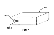
図1では、電子データ記憶カートリッジ100の実施形態の斜視図が示される。この実施形態は二つの状態指示器104を有する。指示器104は電子データ記憶カートリッジ100の背面にあり、それぞれが一色または多色であり得る。各種の情報がこれらの状態指示器によって反映され得る。その情報は例えば、リードアクティブ、ライトアクティブ、書き込み保護、エラー、電力供給、ドライブベイ内にロックされているカートリッジ等である。
次に図2では、電子データ記憶カートリッジ200−1の実施形態のブロック図が示される。本ブロック図は図1の実施形態に対応する。電子データ記憶カートリッジ100内にはインターフェイス回路216があり、コネクタ204と結合される。インターフェイス回路216が状態指示器104を駆動する。記憶カートリッジ内の記憶媒体212は、電子データ記憶カートリッジ(200−1)のため情報を保持する。記憶媒体212はハードドライブまたはフラッシュメモリベースであり得る。本実施形態では、記憶媒体212はカートリッジ208内に設置された標準の既製の(off−the−shelf)ハードドライブである。ショック緩衝材が記憶媒体212の取付けに使用され得る。
図3では、電子データ記憶カートリッジ100−2の別の実施形態の斜視図が示される。状態指示器104に加えて、本実施形態は電子データ記憶カートリッジ100−2の背面にイジェクトボタン304を含む。イジェクトボタン304は電子式または機械式ボタンで、電子データ記憶カートリッジ100−2およびドライブベイに対して、ユーザーが電子データ記憶カートリッジ100−2のシャットダウンとイジェクトを望むことを指示する。イジェクトボタン304の作動は、一部の実施形態に含まれる任意の機械式ロックを非作動化する。
次に図4では、電子データ記憶カートリッジ200−2の別の実施形態のブロック図が示される。本ブロック図は図3の実施形態に対応する。コネクタ204は、記憶媒体212およびマイクロコントローラまたはプロセッサ412と結合される。マイクロコントローラ412は、記憶媒体、インターフェイス回路416および確認(ID)デバイス408とインターフェイスし得る。インターフェイス回路416は、イジェクトボタン304、状態指示器104および衝撃センサー420とインターフェイスする。他の実施形態はこれらのブロックのサブセットを含み得る。
IDデバイス408は、電子データ記憶カートリッジ200−2用の独自のシリアル番号を持つ。一部の実施形態は、IDデバイスの中にRFIDタグを含み得、さらにフレキシブルな方法での電子データ記憶カートリッジ200−2の読取を可能とする。このIDデバイスは、状態、認証キー、認可キー、暗号化キー、作動時間、エラー状態等の他の情報をも記憶することができる。
衝撃センサーが本実施形態において、記憶媒体212が可動部分を有する場合には、それを保護するために使用される。例えば、ハードドライブは過度の加速または減速によって損傷し得る。衝撃センサー420は移動を測定し、マイクロコントローラ412に報告し、マイクロコントローラは記憶媒体にハードドライブヘッドを停止させる。
図5では、電子データ記憶カートリッジ200−3の別の実施形態のブロック図が示される。本実施形態は、記憶媒体212の中でマイクロプロセッサ504を使用し、記憶媒体212の外部の回路を制御する。記憶媒体のファームウエアは、これらの追加機能をサポートするために既製のハードディスク用に書き換えられ得る。本図は機械的に作動される書き込み保護スイッチ406の使用を示す。作動中は、電子データ記憶カートリッジ200−3は、記憶データを改訂することはできない。
次に図6A、図6Bおよび図6Cでは、電子データ記憶カートリッジ100のさらに別の実施形態における、背面図600、上から見た断面図(top−sectional view)610および前面図620が示される。図6Aは二つの露出した導波路端608を有する電子データ記憶カートリッジ100のコネクタ端を示す。導波路端608は光コネクタと考えられる。図6Bは電子記憶媒体(例えばHDD)212およびその専用コネクタ204と、導波路612とを含む、電子データ記憶カートリッジの内部を示す。この導波路はドライブベイのエミッタからの光を、電子データ記憶カートリッジ100の背面に結合する。図6Cは電子データ記憶カートリッジの反対側(電子データ記憶カートリッジ100がその嵌合ドライブベイに挿入されるとき、ユーザーに面する)および導波路612の指示器端616を示す。この実施形態は二つの導波路612を有し、それぞれが単色または多色の光を結合し得る。
図7Aでは、ドライブベイ回路カード700の実施形態のブロック図が示される。電子データ記憶カートリッジ100は、記憶媒体への嵌合コネクタ712を含むアセンブリ700に通常結合される。本アセンブリ(一般的にはPCB)は、LEDのような一つ以上の光源708をも含み、電子データ記憶カートリッジが嵌合コネクタに挿入されるときには、その光源は導波路端と整列する。LEDはPCB上に含まれる電子回路704によって制御され、各種の状態条件を指示する。一つ以上のLEDがオンされると、電子データ記憶カートリッジ100前面の導波路612の指示端616は、対応するLEDから放射される光によって点灯される。
次に図7Bおよび図7Cでは、電子データ記憶カートリッジのさらに別の実施形態の上から見た断面図および前面図が示される。これらはドライブベイ回路カード700と整列して示される。
図8Aでは、ドライブベイ回路カード700の別の実施形態のブロック図が示される。本実施形態は、導波路612が多色LED808と結合され得、単一の導波路612による多色指示を提供する、変更案を示す。一部の実施形態は、ドライブベイ回路カード700上の単色エミッタ、およびカートリッジ208内の別の色のエミッタを有することが可能で、それは共に導波路612に結合される。
次に図8Bでは、電子データ記憶カートリッジ100のさらに別の実施形態の、上から見た断面図が示される。本実施形態は単一の導波路612を示す。この実施形態のコネクタ204は標準PATAまたはSATAインターフェイスである。電子データ記憶カートリッジ100には、追加の電気式インターフェイスは使用されない。
図9では、マルチドライブベイカートリッジシステム900の実施形態の前面図が示される。現行のシステムでは、状態LEDまたは光導波路の機能は、システムのフロントパネルまたはベゼル面に組み入れられている。しかしながら、システム設計がサイズをより小型化するにつれて、フロントパネルには十分な余地がなくなる。図9は発明の使用が重要である一適用例を示す。図9のカートリッジシステム900は、エンクロージャ912の中に密に詰め込まれた、電子データ記憶カートリッジ100の取り外し可能な配列である。使用可能なスペースは、フロントパネルに配置されたそれぞれの電子データ記憶カートリッジのための指示器に対して、適切な余地を提供できない。本適用では、視認可能な指示は明らかにそれ自身の電子データ記憶カートリッジと関連している。共通のセットと制御908とユーザーディスプレイ904が、カートリッジシステム900をナビゲートし制御するために使用される。
本発明の原理が、具体的な装置および方法と関連させて上記に記述されてきたが、本記述は単なる例示としてなされたものであって、本発明の範囲を制限するものではないことは、明確に理解されるべきである。
In electronic data storage cartridges with electrical connections, the present invention has several attributes. First, a visible display can be provided upon insertion of the electronic data storage cartridge and upon clear engagement with the mating connector. In this case, one indicator is turned on (for example, green). The indicator flashes when a data transfer operation occurs. This provides the user with a visible indication that the electronic data storage cartridge should not be removed.
Many data cartridges include a write protection function—usually a mechanical switch that engages a mating system. In many cases, the position of this switch is not visible when the cartridge is loaded. If the electronic data storage cartridge is write protected, a light indicator (eg, red) can be lit. This indicator can alert the user to errors or fault conditions in the electronic data storage cartridge (eg, by flashing). When the indicator emitter is in the drive bay, there is an optical interface or connector to the waveguide in the electronic data storage cartridge.
In FIG. 1, a perspective view of an embodiment of an electronic data storage cartridge 100 is shown. This embodiment has two status indicators 104. The indicators 104 are on the back of the electronic data storage cartridge 100 and can each be one color or multicolor. Various types of information can be reflected by these status indicators. The information includes, for example, read active, write active, write protection, error, power supply, cartridge locked in the drive bay, and the like.
Referring now to FIG. 2, a block diagram of an embodiment of the electronic data storage cartridge 200-1 is shown. This block diagram corresponds to the embodiment of FIG. Within the electronic data storage cartridge 100 is an
In FIG. 3, a perspective view of another embodiment of an electronic data storage cartridge 100-2 is shown. In addition to the status indicator 104, this embodiment includes an
Turning next to FIG. 4, a block diagram of another embodiment of an electronic data storage cartridge 200-2 is shown. This block diagram corresponds to the embodiment of FIG.
The
In this embodiment, the impact sensor is used to protect the
In FIG. 5, a block diagram of another embodiment of an electronic data storage cartridge 200-3 is shown. In this embodiment, the
6A, 6B, and 6C, a
In FIG. 7A, a block diagram of an embodiment of a drive
Next, in FIGS. 7B and 7C, a cross-sectional view and a front view, as seen from above, of yet another embodiment of an electronic data storage cartridge are shown. These are shown aligned with the drive
In FIG. 8A, a block diagram of another embodiment of a drive
Referring now to FIG. 8B, a cross-sectional view from above of yet another embodiment of the electronic data storage cartridge 100 is shown. This embodiment shows a
In FIG. 9, a front view of an embodiment of a multi-drive
Although the principles of the present invention have been described above in connection with specific apparatus and methods, the description has been made by way of example only and is not intended to limit the scope of the invention. It should be clearly understood.
Claims (23)
カートリッジ本体であって、少なくとも二つの外部表面を含む該カートリッジ本体と、
該計算システムに着脱可能なコネクタであって、該カートリッジ本体の外部の情報を結合する該コネクタと、
該二つの外部表面の間の光を結合するように構成される光導波路と、
該コネクタに結合されるハードディスクドライブと
を備える、記憶カートリッジ。 An electronic data storage cartridge that is removable from a computing system,
A cartridge body comprising at least two external surfaces;
A connector detachably attached to the computing system, the connector coupling information external to the cartridge body;
An optical waveguide configured to couple light between the two outer surfaces;
And a hard disk drive coupled to the connector.
該ベイは前記コネクタ用の嵌合コネクタを備え、
該ベイは該カートリッジ本体の着脱可能な挿入を可能とする、
請求項1に記載の計算システムに着脱可能な電子データ記憶カートリッジ。 The cartridge body is configured such that at least 20% of the length or width of the cartridge body can be removably inserted into the bay;
The bay includes a mating connector for the connector,
The bay allows for detachable insertion of the cartridge body;
An electronic data storage cartridge removable from the computing system according to claim 1.
前記記憶カートリッジのアクセスと、
前記記憶カートリッジへの給電と
のうちの少なくとも一つを指示する状態指示器を提供する、請求項1に記載の計算システムに着脱可能な電子データ記憶カートリッジ。 One end of the optical waveguide is
Accessing the storage cartridge;
The electronic data storage cartridge attachable to and detachable from the computing system according to claim 1, wherein a status indicator for indicating at least one of power supply to the storage cartridge is provided.
カートリッジ本体であって、外部表面を含む該カートリッジ本体と、
該計算システムに着脱可能なコネクタであって、該カートリッジ本体の外部の情報を結合する該コネクタと、
該外部表面の外部からの光を該カートリッジ本体の内部に結合するように構成される光導波路と、
該コネクタに結合される記憶媒体と
を備える、記憶カートリッジ。 An electronic data storage cartridge that is removable from a computing system,
A cartridge body comprising the exterior surface; and
A connector detachably attached to the computing system, the connector coupling information external to the cartridge body;
An optical waveguide configured to couple light from outside the outer surface into the interior of the cartridge body;
And a storage medium coupled to the connector.
該ベイは前記コネクタ用の嵌合コネクタを備え、
該ベイは該カートリッジ本体の着脱可能な挿入を可能とする、
請求項11に記載の計算システムに着脱可能な電子データ記憶カートリッジ。 The cartridge body is configured such that at least 20% of the length or width of the cartridge body can be removably inserted into the bay;
The bay includes a mating connector for the connector,
The bay allows for detachable insertion of the cartridge body;
An electronic data storage cartridge removable from the computing system according to claim 11.
カートリッジ本体であって、外部表面を含む該カートリッジ本体と、
該計算システムに着脱可能なコネクタであって、該カートリッジ本体の外部の情報を結合する該コネクタと、
該外部表面を通じて入射光を運ぶように構成される光導波路と、
該コネクタに結合される記憶媒体と
を備え、
該カートリッジ本体は、該カートリッジ本体の少なくとも20%の長さまたは幅が、ベイの中に着脱可能に挿入できるように構成され、
該ベイは該コネクタ用の嵌合コネクタを備え、
該ベイは該カートリッジ本体の着脱可能な挿入を可能とする、
記憶カートリッジ。 An electronic data storage cartridge removable from a computing system, the storage cartridge comprising:
A cartridge body comprising the exterior surface; and
A connector detachably attached to the computing system, the connector coupling information external to the cartridge body;
An optical waveguide configured to carry incident light through the external surface;
A storage medium coupled to the connector;
The cartridge body is configured such that at least 20% of the length or width of the cartridge body can be removably inserted into the bay;
The bay includes a mating connector for the connector;
The bay allows for detachable insertion of the cartridge body;
Storage cartridge.
Applications Claiming Priority (3)
| Application Number | Priority Date | Filing Date | Title |
|---|---|---|---|
| US58608704P | 2004-07-06 | 2004-07-06 | |
| US11/149,623 US20060010458A1 (en) | 2004-07-06 | 2005-06-10 | Electronic storage cartridge |
| PCT/US2005/020966 WO2006014221A2 (en) | 2004-07-06 | 2005-06-14 | Electronic storage cartridge |
Publications (2)
| Publication Number | Publication Date |
|---|---|
| JP2008506215A true JP2008506215A (en) | 2008-02-28 |
| JP2008506215A5 JP2008506215A5 (en) | 2008-07-03 |
Family
ID=35542799
Family Applications (1)
| Application Number | Title | Priority Date | Filing Date |
|---|---|---|---|
| JP2007520317A Pending JP2008506215A (en) | 2004-07-06 | 2005-06-14 | Electronic data storage cartridge |
Country Status (5)
| Country | Link |
|---|---|
| US (2) | US20060010458A1 (en) |
| EP (1) | EP2008278A4 (en) |
| JP (1) | JP2008506215A (en) |
| BR (1) | BRPI0512600A8 (en) |
| WO (1) | WO2006014221A2 (en) |
Families Citing this family (32)
| Publication number | Priority date | Publication date | Assignee | Title |
|---|---|---|---|---|
| US20060010458A1 (en) | 2004-07-06 | 2006-01-12 | Prostor Systems, Inc. | Electronic storage cartridge |
| US8019908B2 (en) | 2004-07-06 | 2011-09-13 | Tandberg Data Holdings S.A.R.L. | Data replication systems and methods |
| US7310196B1 (en) * | 2004-12-02 | 2007-12-18 | Maxtor Corporation | Parking a transducer responsive to a park signal |
| TWM279952U (en) * | 2005-06-30 | 2005-11-01 | Mapower Electronics Co Ltd | Electronic drop protection system of external hard-disk box |
| US7493430B2 (en) * | 2005-07-14 | 2009-02-17 | Quantum Corporation | Data flow control and bridging architecture enhancing performance of removable data storage systems |
| US7484026B2 (en) * | 2005-11-28 | 2009-01-27 | Visteon Global Technologies, Inc. | System and method for media damage prevention on a portable player |
| US20070155201A1 (en) * | 2006-01-05 | 2007-07-05 | Quantum Corporation, A Delaware Corporation | PCB edge connector |
| US7573705B2 (en) * | 2006-01-12 | 2009-08-11 | Prostor Systems, Inc. | Data cartridge with electrostatic discharge protection |
| US7866996B2 (en) * | 2006-05-24 | 2011-01-11 | Sandisk Il Ltd. | Internal UFD |
| US20110076867A1 (en) * | 2006-06-28 | 2011-03-31 | Nitzan Achsaf | Internal ufd |
| US7612994B2 (en) * | 2006-10-31 | 2009-11-03 | Prostor Systems, Inc. | Hard drive cartridge protection |
| US7779220B1 (en) * | 2007-03-15 | 2010-08-17 | Quantum Corporation | Password-based media cartridge authentication |
| JP2009087124A (en) * | 2007-10-01 | 2009-04-23 | Buffalo Inc | Storage device and storage device access control method |
| AU2008347133B2 (en) * | 2008-01-09 | 2013-11-14 | Iosafe, Inc. | Low cost disaster resistant data storage module |
| US20090282180A1 (en) * | 2008-05-06 | 2009-11-12 | Ricky Kuan | Plug-and-play hard disk read/write drive |
| US20100023956A1 (en) * | 2008-07-25 | 2010-01-28 | Prostor Systems, Inc. | Methods for implementation of an eject service for a removable disk drive |
| US20100161895A1 (en) * | 2008-12-22 | 2010-06-24 | Qualls William R | Securing data on data cartridges |
| US20100157766A1 (en) * | 2008-12-22 | 2010-06-24 | Gregg Jody L | Predicting cartridge failure from cartridge memory data |
| US8390949B2 (en) * | 2009-05-18 | 2013-03-05 | Dell Products L.P. | Data loss prevention during a fall of a storage device |
| US8310490B2 (en) * | 2009-05-28 | 2012-11-13 | Tandberg Data Corporation | Display for information storage module |
| US8793413B2 (en) * | 2010-11-09 | 2014-07-29 | Seagate Technology Llc | Adaptable storage cartridge system |
| US8583847B2 (en) * | 2010-12-09 | 2013-11-12 | Dell Products, Lp | System and method for dynamically detecting storage drive type |
| US20140149785A1 (en) * | 2011-10-25 | 2014-05-29 | M. Scott Bunker | Distributed management |
| CN103700380A (en) * | 2012-09-28 | 2014-04-02 | 鸿富锦精密工业(深圳)有限公司 | Optical drive with storage device |
| US9126738B2 (en) * | 2013-02-04 | 2015-09-08 | Pepsico, Inc. | Cartridge for a dispensing system |
| CN104423497A (en) * | 2013-09-11 | 2015-03-18 | 鸿富锦精密电子(天津)有限公司 | Storing device for hard disk |
| US10067902B2 (en) | 2013-09-24 | 2018-09-04 | Hewlett Packard Enterprise Development Lp | Slot based management controller address |
| US10013172B2 (en) * | 2015-07-10 | 2018-07-03 | The Keyw Corporatin | Electronic data storage device with multiple configurable data storage mediums |
| KR20180095766A (en) * | 2017-02-17 | 2018-08-28 | 삼성전자주식회사 | Storage device |
| JP6451764B2 (en) * | 2017-03-22 | 2019-01-16 | 日本電気株式会社 | Disk device and notification method |
| US10861502B2 (en) * | 2017-12-26 | 2020-12-08 | Facebook, Inc. | Apparatus, system, and method for preventing shock-induced hard drive damage |
| US10424331B1 (en) * | 2018-05-21 | 2019-09-24 | International Business Machines Corporation | Remotely controlling a magnetic tape cartridge |
Citations (4)
| Publication number | Priority date | Publication date | Assignee | Title |
|---|---|---|---|---|
| JPS55162133U (en) * | 1979-05-09 | 1980-11-20 | ||
| JPH06337819A (en) * | 1993-05-31 | 1994-12-06 | Fuji Film Micro Device Kk | Memory card |
| US5790374A (en) * | 1996-12-06 | 1998-08-04 | Ncr Corporation | Method and apparatus for providing power activity and fault light support using light conduits for single connector architecture (SCA) disk drives |
| JP2004145866A (en) * | 2002-10-03 | 2004-05-20 | I-O Data Device Inc | Hard disk management device |
Family Cites Families (55)
| Publication number | Priority date | Publication date | Assignee | Title |
|---|---|---|---|---|
| USD260881S (en) | 1979-03-22 | 1981-09-22 | Atari, Inc. | Memory module housing |
| US5075805A (en) * | 1988-02-25 | 1991-12-24 | Tandon Corporation | Disk drive controller system |
| USD311737S (en) | 1988-12-07 | 1990-10-30 | Plus Development | Removable hard disk drive module |
| US5216582A (en) | 1992-02-10 | 1993-06-01 | Quantum Corporation | Shock mounted disk drive module having snap-lock cover |
| US5887145A (en) | 1993-09-01 | 1999-03-23 | Sandisk Corporation | Removable mother/daughter peripheral card |
| DE69513143T2 (en) | 1995-04-18 | 2000-08-17 | Iomega Corp | Leading backdrop in cassette |
| US5721655A (en) | 1996-07-15 | 1998-02-24 | Electronic Data Systems Corporation | Method for labeling a removable media cartridge |
| US5986992A (en) | 1997-04-07 | 1999-11-16 | Sony America | Disk cartridge with programmable LCD capacity display indicator |
| US6272010B1 (en) * | 1998-01-27 | 2001-08-07 | Dell Usa, L.P. | Peripheral device mounting apparatus |
| CA2324006A1 (en) * | 1998-03-16 | 1999-09-23 | Iomega Corporation | Apparatus and method for direct connection of a mass storage drive to a digital appliance |
| US6160797A (en) | 1998-04-03 | 2000-12-12 | Starguide Digital Networks, Inc. | Satellite receiver/router, system, and method of use |
| US6064569A (en) * | 1998-11-12 | 2000-05-16 | Dell Usa, L.P. | Computer and hard drive having a multiple drop light pipe |
| USD413592S (en) | 1998-11-13 | 1999-09-07 | Quantum Corporation | Tape cartridge |
| US6611394B1 (en) * | 1998-12-18 | 2003-08-26 | Sony Corporation | Recording medium, tape drive, and method for identifying type of recording medium |
| US6487049B1 (en) | 1998-12-23 | 2002-11-26 | Iomega Corporation | Drive heads for storage media drive with displaced pair of sensors |
| US6457992B2 (en) * | 1999-02-08 | 2002-10-01 | 3Com Corporation | Visual feedback system for electronic device |
| JP4672824B2 (en) * | 1999-03-17 | 2011-04-20 | ソニー株式会社 | Tape drive device, recording medium |
| US6614751B1 (en) * | 1999-03-18 | 2003-09-02 | Hisashi Katao | Disk cartridge, optical disk drive, optical library and optical storage system |
| US7507119B2 (en) * | 2000-01-06 | 2009-03-24 | Super Talent Electronics, Inc. | USB device with integrated USB plug with USB-substrate supporter inside |
| US6231224B1 (en) * | 1999-09-22 | 2001-05-15 | International Business Machines Corporation | Light pipe guide and carrier for hard disk drive |
| US6431718B1 (en) * | 1999-09-22 | 2002-08-13 | International Business Machines Corporation | Interconnector and light pipe guide for disk drive and disk drive carrier |
| US6419403B1 (en) * | 2000-01-04 | 2002-07-16 | International Business Machines Corporation | System and method for optically coupling component service interfaces |
| US7535088B2 (en) * | 2000-01-06 | 2009-05-19 | Super Talent Electronics, Inc. | Secure-digital (SD) flash card with slanted asymmetric circuit board |
| US6717762B1 (en) * | 2000-06-09 | 2004-04-06 | Iomega Corporation | Method and apparatus for making a drive compatible with a removable cartridge |
| USD458643S1 (en) | 2000-08-04 | 2002-06-11 | Nintendo Co., Ltd. | Information storage cartridge for electronic game machine |
| US6618795B2 (en) * | 2001-01-24 | 2003-09-09 | Sony Corporation | Method and apparatus for concurrent access to a sequential device |
| US20020135938A1 (en) | 2001-02-21 | 2002-09-26 | Fuji Photo Film Co., Ltd. | Record medium cartridge and molded resin parts |
| US6957291B2 (en) * | 2001-03-29 | 2005-10-18 | Quantum Corporation | Removable disk storage array emulating tape library having backup and archive capability |
| USD478358S1 (en) | 2001-04-02 | 2003-08-12 | Nintendo Co., Ltd. | Information storage cartridge for electronic game machine |
| US6865640B2 (en) * | 2001-04-26 | 2005-03-08 | International Business Machines Corporation | Hard disk drive library |
| US6717769B2 (en) * | 2001-05-11 | 2004-04-06 | Iomega Corporation | Eject button for disk drive with light pipe |
| US6728187B2 (en) * | 2001-06-07 | 2004-04-27 | Hewlett-Packard Development Company, L.P. | Light pipe assembly for an optical drive |
| US6717765B2 (en) | 2001-06-22 | 2004-04-06 | Iomega Corporation | Method and circuit for sensing back EMF |
| US6473300B1 (en) * | 2001-06-27 | 2002-10-29 | Sun Microsystems, Inc. | Light conduit for a storage device carrier assembly |
| USD470851S1 (en) | 2001-12-18 | 2003-02-25 | Atsushi Nishio | Memory card reader with a hub for a universal serial bus |
| US6762930B2 (en) * | 2002-01-17 | 2004-07-13 | Hewlett-Packard Development Company, L.P. | Form factor card with status indicator |
| US7349930B2 (en) * | 2002-02-05 | 2008-03-25 | Quantum Corporation | Emulated backup tape drive using data compression |
| US6892275B2 (en) * | 2002-02-05 | 2005-05-10 | Quantum Corporation | Storage system utilizing an active subset of drives during data storage and retrieval operations |
| DE10309482B4 (en) | 2002-03-11 | 2006-10-12 | Teac Corp., Musashino | Support foot device for a device housing |
| US6831831B2 (en) * | 2002-04-11 | 2004-12-14 | Bruce A Bicknell | Disc storage subsystem having improved reliability |
| USD474193S1 (en) | 2002-07-11 | 2003-05-06 | Sony Corporation | Tape cartridge |
| US6873524B2 (en) | 2002-08-15 | 2005-03-29 | Audavi Corporation | Data storage device |
| TW568323U (en) | 2002-09-27 | 2003-12-21 | Lite On It Corp | Cap opening and closing device for cap-lifting CD-ROM drive |
| US20040081054A1 (en) | 2002-10-22 | 2004-04-29 | Riospring, Inc. | Finger grip for disk drive |
| US6876547B2 (en) * | 2002-11-14 | 2005-04-05 | Dell Products L.P. | Hard drive carrier |
| US20040181388A1 (en) * | 2003-03-11 | 2004-09-16 | Yung Yip | System having tape drive emulator and data tape cartridge housing carrying multiple disk drives |
| JP4559046B2 (en) * | 2003-08-04 | 2010-10-06 | 株式会社日立製作所 | Virtual tape library device |
| US20050193235A1 (en) * | 2003-08-05 | 2005-09-01 | Miklos Sandorfi | Emulated storage system |
| JP4480386B2 (en) | 2003-11-28 | 2010-06-16 | 株式会社日立製作所 | Disk array device and data relay method for disk array device |
| US7307836B2 (en) * | 2004-03-15 | 2007-12-11 | Xyratex Technology Limited | Data storage device carrier and chassis |
| US7008240B1 (en) * | 2004-04-16 | 2006-03-07 | Super Talent Electronics, Inc. | PC card assembly |
| US8019908B2 (en) * | 2004-07-06 | 2011-09-13 | Tandberg Data Holdings S.A.R.L. | Data replication systems and methods |
| US20060010458A1 (en) | 2004-07-06 | 2006-01-12 | Prostor Systems, Inc. | Electronic storage cartridge |
| US7476105B2 (en) * | 2004-08-06 | 2009-01-13 | Super Talent Electronics, Inc. | Super-digital (SD) flash card with asymmetric circuit board and mechanical switch |
| USD523859S1 (en) | 2005-04-04 | 2006-06-27 | Hewlett-Packard Development Company, L.P. | Media cartridge |
-
2005
- 2005-06-10 US US11/149,623 patent/US20060010458A1/en not_active Abandoned
- 2005-06-14 JP JP2007520317A patent/JP2008506215A/en active Pending
- 2005-06-14 EP EP05758581A patent/EP2008278A4/en not_active Withdrawn
- 2005-06-14 BR BRPI0512600A patent/BRPI0512600A8/en not_active IP Right Cessation
- 2005-06-14 WO PCT/US2005/020966 patent/WO2006014221A2/en active Application Filing
-
2008
- 2008-05-08 US US12/117,507 patent/US8060893B2/en not_active Expired - Fee Related
Patent Citations (4)
| Publication number | Priority date | Publication date | Assignee | Title |
|---|---|---|---|---|
| JPS55162133U (en) * | 1979-05-09 | 1980-11-20 | ||
| JPH06337819A (en) * | 1993-05-31 | 1994-12-06 | Fuji Film Micro Device Kk | Memory card |
| US5790374A (en) * | 1996-12-06 | 1998-08-04 | Ncr Corporation | Method and apparatus for providing power activity and fault light support using light conduits for single connector architecture (SCA) disk drives |
| JP2004145866A (en) * | 2002-10-03 | 2004-05-20 | I-O Data Device Inc | Hard disk management device |
Also Published As
| Publication number | Publication date |
|---|---|
| WO2006014221A3 (en) | 2009-01-22 |
| EP2008278A4 (en) | 2010-12-15 |
| EP2008278A2 (en) | 2008-12-31 |
| US8060893B2 (en) | 2011-11-15 |
| BRPI0512600A (en) | 2008-03-25 |
| BRPI0512600A8 (en) | 2019-01-15 |
| US20060010458A1 (en) | 2006-01-12 |
| WO2006014221A2 (en) | 2006-02-09 |
| US20090310253A1 (en) | 2009-12-17 |
Similar Documents
| Publication | Publication Date | Title |
|---|---|---|
| JP2008506215A (en) | Electronic data storage cartridge | |
| US7251132B1 (en) | Receiving frame having removable computer drive carrier and lock | |
| EP0689127B1 (en) | Recording and/or reproducing system and data backup system | |
| JP2008506215A5 (en) | ||
| US9053249B2 (en) | Removable memory cartridge and docking station compatible with media drive expansion slots | |
| JP4099579B2 (en) | Hard disk system | |
| CN101238432A (en) | Mass storage system with user interface | |
| CN102411554A (en) | Hot-plugging method, apparatus and terminal device for USB (universal serial bus) storage devices | |
| US20080002273A1 (en) | Medium storing apparatus and medium storing system | |
| JP4909383B2 (en) | Hard disk management device | |
| CN102597903B (en) | Display for information storage module | |
| EP1661006B1 (en) | Removable hard drive assembly, computer with a removable hard disk drive, method of initializing and operating a removable hard drive | |
| US6907314B2 (en) | Inventory control device | |
| US8082403B1 (en) | Method for certifying erasure of one or more data storage disk drives | |
| CN101432811A (en) | Electronic storage cartridge | |
| JP6060628B2 (en) | Library device | |
| JP2004145866A (en) | Hard disk management device | |
| US20050031298A1 (en) | Electronic equipment device and method for protecting electronic equipment | |
| WO2007113455A1 (en) | Data security | |
| JPH05233475A (en) | Information processor | |
| CN201237904Y (en) | Hard disk ROM with security function | |
| JP2007073160A (en) | Peripheral device | |
| CN110765466A (en) | Hard disk with encryption and decryption functions and application system thereof | |
| US20030088334A1 (en) | Automatic tape loader robotics control interface system | |
| JPH1125247A (en) | Information storage auxiliary device |
Legal Events
| Date | Code | Title | Description |
|---|---|---|---|
| A521 | Request for written amendment filed |
Free format text: JAPANESE INTERMEDIATE CODE: A523 Effective date: 20080513 |
|
| A621 | Written request for application examination |
Free format text: JAPANESE INTERMEDIATE CODE: A621 Effective date: 20080513 |
|
| A977 | Report on retrieval |
Free format text: JAPANESE INTERMEDIATE CODE: A971007 Effective date: 20100816 |
|
| A131 | Notification of reasons for refusal |
Free format text: JAPANESE INTERMEDIATE CODE: A131 Effective date: 20100922 |
|
| A601 | Written request for extension of time |
Free format text: JAPANESE INTERMEDIATE CODE: A601 Effective date: 20101221 |
|
| A602 | Written permission of extension of time |
Free format text: JAPANESE INTERMEDIATE CODE: A602 Effective date: 20110104 |
|
| A521 | Request for written amendment filed |
Free format text: JAPANESE INTERMEDIATE CODE: A523 Effective date: 20110112 |
|
| A02 | Decision of refusal |
Free format text: JAPANESE INTERMEDIATE CODE: A02 Effective date: 20110714 |