JP2008501200A - Reconfigurable airflow director for modular blade chassis - Google Patents
Reconfigurable airflow director for modular blade chassis Download PDFInfo
- Publication number
- JP2008501200A JP2008501200A JP2007515696A JP2007515696A JP2008501200A JP 2008501200 A JP2008501200 A JP 2008501200A JP 2007515696 A JP2007515696 A JP 2007515696A JP 2007515696 A JP2007515696 A JP 2007515696A JP 2008501200 A JP2008501200 A JP 2008501200A
- Authority
- JP
- Japan
- Prior art keywords
- airflow
- director
- inlet
- duct
- chassis
- Prior art date
- Legal status (The legal status is an assumption and is not a legal conclusion. Google has not performed a legal analysis and makes no representation as to the accuracy of the status listed.)
- Pending
Links
- 238000005192 partition Methods 0.000 claims abstract description 10
- 238000000034 method Methods 0.000 claims description 18
- 230000007246 mechanism Effects 0.000 claims description 5
- 230000008878 coupling Effects 0.000 claims description 4
- 238000010168 coupling process Methods 0.000 claims description 4
- 238000005859 coupling reaction Methods 0.000 claims description 4
- 238000007599 discharging Methods 0.000 claims 2
- 230000003094 perturbing effect Effects 0.000 claims 1
- 230000001105 regulatory effect Effects 0.000 claims 1
- 230000013011 mating Effects 0.000 abstract description 12
- 230000003247 decreasing effect Effects 0.000 abstract 1
- 239000000758 substrate Substances 0.000 description 23
- 238000001816 cooling Methods 0.000 description 11
- 239000000463 material Substances 0.000 description 3
- 239000002184 metal Substances 0.000 description 3
- 230000008859 change Effects 0.000 description 2
- 238000013461 design Methods 0.000 description 2
- 230000006870 function Effects 0.000 description 2
- 230000009471 action Effects 0.000 description 1
- 230000008901 benefit Effects 0.000 description 1
- 238000005266 casting Methods 0.000 description 1
- 230000003750 conditioning effect Effects 0.000 description 1
- 238000011161 development Methods 0.000 description 1
- 230000002708 enhancing effect Effects 0.000 description 1
- 238000005242 forging Methods 0.000 description 1
- 230000020169 heat generation Effects 0.000 description 1
- 230000006872 improvement Effects 0.000 description 1
- 238000001746 injection moulding Methods 0.000 description 1
- 238000009434 installation Methods 0.000 description 1
- 238000004519 manufacturing process Methods 0.000 description 1
- 230000004048 modification Effects 0.000 description 1
- 238000012986 modification Methods 0.000 description 1
- 238000010137 moulding (plastic) Methods 0.000 description 1
- 230000001737 promoting effect Effects 0.000 description 1
- 238000009745 resin transfer moulding Methods 0.000 description 1
- 239000004065 semiconductor Substances 0.000 description 1
- 239000000243 solution Substances 0.000 description 1
- 238000012546 transfer Methods 0.000 description 1
- 230000007704 transition Effects 0.000 description 1
- 238000002604 ultrasonography Methods 0.000 description 1
- 238000007666 vacuum forming Methods 0.000 description 1
Images


Classifications
-
- H—ELECTRICITY
- H05—ELECTRIC TECHNIQUES NOT OTHERWISE PROVIDED FOR
- H05K—PRINTED CIRCUITS; CASINGS OR CONSTRUCTIONAL DETAILS OF ELECTRIC APPARATUS; MANUFACTURE OF ASSEMBLAGES OF ELECTRICAL COMPONENTS
- H05K7/00—Constructional details common to different types of electric apparatus
- H05K7/20—Modifications to facilitate cooling, ventilating, or heating
- H05K7/20536—Modifications to facilitate cooling, ventilating, or heating for racks or cabinets of standardised dimensions, e.g. electronic racks for aircraft or telecommunication equipment
- H05K7/20554—Forced ventilation of a gaseous coolant
- H05K7/20563—Forced ventilation of a gaseous coolant within sub-racks for removing heat from electronic boards
-
- G—PHYSICS
- G06—COMPUTING; CALCULATING OR COUNTING
- G06F—ELECTRIC DIGITAL DATA PROCESSING
- G06F1/00—Details not covered by groups G06F3/00 - G06F13/00 and G06F21/00
- G06F1/16—Constructional details or arrangements
- G06F1/20—Cooling means
-
- H—ELECTRICITY
- H05—ELECTRIC TECHNIQUES NOT OTHERWISE PROVIDED FOR
- H05K—PRINTED CIRCUITS; CASINGS OR CONSTRUCTIONAL DETAILS OF ELECTRIC APPARATUS; MANUFACTURE OF ASSEMBLAGES OF ELECTRICAL COMPONENTS
- H05K7/00—Constructional details common to different types of electric apparatus
- H05K7/20—Modifications to facilitate cooling, ventilating, or heating
Landscapes
- Engineering & Computer Science (AREA)
- Physics & Mathematics (AREA)
- Thermal Sciences (AREA)
- Microelectronics & Electronic Packaging (AREA)
- Aviation & Aerospace Engineering (AREA)
- Theoretical Computer Science (AREA)
- General Physics & Mathematics (AREA)
- General Engineering & Computer Science (AREA)
- Human Computer Interaction (AREA)
- Cooling Or The Like Of Electrical Apparatus (AREA)
- Air-Flow Control Members (AREA)
- Automatic Cycles, And Cycles In General (AREA)
- Body Structure For Vehicles (AREA)
- Structures Of Non-Positive Displacement Pumps (AREA)
Abstract
モジュラブレードシャーシ用の再構成可能な気流ディレクタである。前記気流ディレクタは、調整可能な入口および/または出口をもつ複数のダクトチャネルを含む。前記気流ディレクタは再構成されて、選択されたブレードや個々のブレード上の選択された領域に対する気流量を調整することができる。一つの実施の形態においては、スナップ嵌合する嵌合気流ブロックの使用により、選択された入口あるいは出口の全てあるいは一部を遮蔽して、対応するダクトチャネルに対する気流調整を行う。一つの実施の形態においては、隣り合う入口の大きさの増減を、調整可能な入口翼板を用いて行う。一つの実施の形態においては、前記気流ディレクタが多数の気流ディレクタモジュールからなり、各気流ディレクタモジュールは外郭体を有し、該外郭体はそこから延びてそれぞれの間に多数の気流チャネルを形成する複数の隔壁を有しており、前記気流ディレクタモジュールは積層されることで複数のダクトチャネルを構成する。多数のホットスワップ可能なファンを含むモジュラファンアセンブリを使用して、前記気流ディレクタの前記ダクトチャネルに気流を押し込む、および/または、引き込む。
【選択図】図7bA reconfigurable airflow director for modular blade chassis. The airflow director includes a plurality of duct channels having adjustable inlets and / or outlets. The airflow director can be reconfigured to adjust the airflow for selected blades or selected areas on individual blades. In one embodiment, the use of snap-fit mating airflow blocks shields all or a portion of the selected inlet or outlet and provides airflow regulation for the corresponding duct channel. In one embodiment, the size of adjacent inlets is increased or decreased using adjustable inlet vanes. In one embodiment, the airflow director comprises a plurality of airflow director modules, each airflow director module having an outer body that extends from there to form a plurality of airflow channels therebetween. A plurality of partition walls are provided, and the airflow director modules are stacked to form a plurality of duct channels. A modular fan assembly including a number of hot-swappable fans is used to push and / or draw airflow into the duct channel of the airflow director.
[Selection] Figure 7b
Description
発明分野は大まかにコンピュータ・電気通信装置に関しており、特に、コンピュータ・電気通信装置のシャーシ用の再構成可能な気流ディレクタに関しているが、それに限定はされない。 The field of invention relates generally to computer and telecommunications equipment, and more particularly, but not exclusively, to a reconfigurable airflow director for a computer and telecommunications equipment chassis.
高度電気通信アーキテクチャ(ATCA)(高度TCAとも称される)規格は、次世代電気通信やデータセンタ装置に産業基準高性能、不良耐性、拡張性解決法を実現する、開放スイッチ構成を元としたプラットフォームを定義している。ATCA規格開発はPCI産業コンピュータ業界(PICMG)内で実行されている。 Advanced Telecommunications Architecture (ATCA) (also known as Advanced TCA) standards are based on open switch configurations that provide industry standard high performance, fault tolerance, and scalability solutions for next generation telecommunications and data center equipment A platform is defined. ATCA standard development is carried out within the PCI Industrial Computer Industry (PICMG).
高度TCA3.0基準仕様は、ホットスワップ可能なブレード間のスイッチ構成接続に基づいた既製品(オフザシェルフの)モジュラシャーシの物理的・電気的特徴を定義している。この仕様により、ATCA準拠基板におけるフレーム(ラック)およびシェルフ(シャーシ)フォーム・ファクタ、コアバックプレーン構成接続性、電力、冷却、管理インターフェース、および電気機械仕様が定義されている。電気機械仕様は現行のIEC60297EuroCardフォーム・ファクタに基づいており、様々なベンダーからの装置であってもモジュラ形式での組み込みを実現し、操作を保証する。ATCA3.0を基にした仕様はさらに、一基板につき200ワット(W)の電力予算を定義しており、マルチプロセッサ・アーキテクチャやマルチギガバイトの基板上メモリを備えた高性能サーバを実現する。 The advanced TCA 3.0 standard specification defines the physical and electrical characteristics of off-the-shelf (off-the-shelf) modular chassis based on switch configuration connections between hot-swappable blades. This specification defines the frame (rack) and shelf (chassis) form factor, core backplane configuration connectivity, power, cooling, management interface, and electromechanical specifications on ATCA compliant boards. The electromechanical specification is based on the current IEC 60297 EuroCard form factor, which allows devices from various vendors to be incorporated in a modular format to ensure operation. The specification based on ATCA 3.0 further defines a power budget of 200 watts (W) per board, realizing a high performance server with multiprocessor architecture and multi-gigabyte on-board memory.
ATCA規格は規格化された電気通信・コンピュータ部材インターフェースおよび相互運用可能性の提供にあたって正しい方向への一歩前進ではあるが、設計面では幾らか限界がある。特に、一基板スロットにつき200Wの電力放出ということは、熱源の位置を特定することなしに、一基板について生成され得る熱量を制限する(200W制限は一スロットを占有する基板への適用である。多数のスロットを占有している基板にはこれより高い電力放出が許可される。例えば二つのスロットを占有する前面基板は400W制限となる)。常に上昇し続けている帯域への要望に応えるために、装置機能が向上する必要があり、他の基板部材の改良のなかでも、とりわけ高速プロセッサが必要になる。同一の半導体製造プロセスを考慮すると、速度と消費電力との間には直接的な関係がある、つまりプロセッサ速度が速くなると、該プロセッサの消費電力も多くなり、該プロセッサにホストしているATCA基板からの放熱量も多くならざるを得ない。このATCAを元とする仕様により定義される厳格な基板・シェルフのフォーム・ファクタを考慮に入れると、プロセッサなどの高電力部材を十分に冷却することが、200Wのうちの大半がこういった部材により消費される理由から、課題となる。 While the ATCA standard is one step in the right direction in providing a standardized telecommunications / computer component interface and interoperability, it has some limitations in design. In particular, a 200 W power release per board slot limits the amount of heat that can be generated for a board without locating the heat source (the 200 W limit is an application to a board that occupies one slot. A board that occupies a large number of slots is allowed to emit higher power (for example, a front board that occupies two slots is limited to 400W). In order to meet the ever-increasing demand for bandwidth, the device function needs to be improved, and a high-speed processor is required among other substrate member improvements. Considering the same semiconductor manufacturing process, there is a direct relationship between speed and power consumption, that is, as the processor speed increases, the power consumption of the processor increases, and the ATCA board hosted in the processor The amount of heat released from must be increased. Taking into account the strict board / shelf form factor defined by this ATCA-based specification, most high power components such as processors can be sufficiently cooled by 200% of these components. It becomes a problem because it is consumed by.
本発明の上述の側面や、その他の多くの付随的利点は、次に続く本発明の詳細な説明を添付図面と併せて読めば明かとなろう。ここでは、そうでないと明記していない限り様々な図面を通じて同様の参照版号は同様の部材を示す。 The foregoing aspects of the invention and many other attendant advantages will become apparent from the following detailed description of the invention when read in conjunction with the accompanying drawings. Here, like reference numerals refer to like parts throughout the various figures unless otherwise specified.
コンピュータ・電気通信装置シャーシにおける冷却を高める装置および方法の実施の形態を以下に記載する。以下の記載においては発明の実施の形態の完全な理解を促す目的で、ATCA規格に対応した実装例など、さまざまな具体的詳細が記される。しかし、当業者であれば本発明が一以上の該具体的詳細以外にも、その他の方法、部材、素材などを使用して実施可能であることが分かると思われる。他の場合、よく知られた構成、素材、あるいは操作法の詳細は本発明の性質を曖昧にしないために詳述を避ける。 Embodiments of an apparatus and method for enhancing cooling in a computer and telecommunications device chassis are described below. In the following description, various specific details such as implementation examples corresponding to the ATCA standard are described for the purpose of promoting a complete understanding of the embodiments of the invention. However, one of ordinary skill in the art will appreciate that the invention can be practiced using other methods, components, materials, and the like in addition to the one or more specific details. In other instances, well-known structures, materials, or operating details have not been described in detail in order not to obscure the nature of the invention.
本明細書で使用される、本発明の「一つの実施の形態」あるいは「一実施の形態」という参照は、該実施の形態に関連する特定の特徴、構造、あるいは特性が本発明の少なくとも一つの実施の形態に含まれている、ということを意味する。従って、「一つの実施の形態においては」や「一つの実施の形態によると」などの言い回しが本明細書の随所に現れるが、これらは必ずしも全てが同一の実施の形態のことを意味しているとは限らない。さらに、一以上の実施の形態において特定の特徴、構造、あるいは特性を適切な方法で組み合わせてもよい。 As used herein, a reference to “an embodiment” or “an embodiment” of the present invention refers to a particular feature, structure, or characteristic associated with the embodiment. It is included in one embodiment. Thus, phrases such as “in one embodiment” and “according to one embodiment” appear throughout this specification, but all of this means that all of the same embodiment. Not necessarily. Furthermore, certain features, structures, or characteristics may be combined in any suitable manner in one or more embodiments.
以下の数段落において、本発明の実施の形態例がATCA装置実装を対象とした使用文脈において記載されている。しかし、これはこの中で開示された原理や教示の使用をATCA装置に限定するものではない。実際には以下の実施の形態は単に実装の可能な一種の例示にすぎない。一般的に言って、該原理や教示はさまざまな種類のモジュラ電子装置に応用可能であり、この中には電気通信装置・コンピュータ装置が含まれるが、これに限定されるわけでもない。 In the following paragraphs, exemplary embodiments of the invention are described in a usage context intended for ATCA device implementations. However, this does not limit the use of the principles and teachings disclosed therein to ATCA devices. Actually, the following embodiments are merely examples of possible implementations. Generally speaking, the principles and teachings are applicable to various types of modular electronic devices, including but not limited to telecommunications devices and computer devices.
昨今のセントラルセンタ、データセンタ等に設置されている装置の大半は、簡便さ、比較的低いコスト、および実装の簡易性、および信頼性の理由により、空気により冷却されている。この傾向は同様の理由から将来にも引き継がれることが予想される。従って、ATCA仕様で規定されている熱指標は空気冷却に適用される、ほかの冷却方法も許されるが、本明細書には含まれない。一般的には、基板、シェルフ、およびフレームはファン、送風機の助けなしに自然方法により冷却されることや、ファン、送風機の助けを用いた強制的方法により冷却されることができる。選択権は末端ユーザの要請に任されている。 Most devices installed in recent central centers, data centers, and the like are cooled by air for reasons of simplicity, relatively low cost, ease of mounting, and reliability. This trend is expected to continue in the future for similar reasons. Therefore, the thermal index defined in the ATCA specification is applicable to air cooling, but other cooling methods are allowed but are not included in this specification. In general, substrates, shelves, and frames can be cooled by natural methods without the help of fans and blowers, or by forced methods with the help of fans and blowers. The choice is left to the end user's request.
ACTA PICMG3.0ショート・フォーム仕様(2003年1月)の一例に使用されている気流経路を図1に示す。空気は正面下部の空気入口102のシェルフ100から下部プレナム104へと入り、90度上方へ方向を変える。前面基板106と背面遷移モジュール(RTM)108の底端を通る気流は均一に配分されている。前面基板106とRTM108上の熱い部材を空気が通ることで、熱は強制的方法により取り去られる。空気は上端部のサブラックから出ていき、上部プレナム110へ引き寄せられ、90度方向を変え、ファン112によりシェルフ100の背面から排出される。図示された構成に加えて、他の気流経路、冷却方法がACTA規格の元では許可される。
FIG. 1 shows an air flow path used in an example of the ACTA PICMG 3.0 short form specification (January 2003). Air enters the
図1に示した標準冷却構成は幾つかの欠点を持つ。特に、全ての基板に対する気流が略等しいということは、全ての基板の冷却要件が略等しいと仮定している。さらに、個々の基板の「ホットスポット」を考慮に入れずに、ここでも平均的な気流を使用する方法をとっている。これに対して、一般的なATCAシャーシにおける電力消費(およびゆえに熱生成)は不均一であり、ある種の基板が他の種類の基板よりも多くの熱を生成する。さらに、多くの基板においては、ごく少数の部材(プロセッサ等)が該基板の熱の大半を生成するものである。これら部材には適切な気流を与えないと過熱状態となる可能性がある。 The standard cooling configuration shown in FIG. 1 has several drawbacks. In particular, the fact that the airflow for all the substrates is approximately equal assumes that the cooling requirements for all the substrates are approximately equal. In addition, the average airflow is used here again without taking into account the “hot spots” of the individual substrates. In contrast, power consumption (and hence heat generation) in a typical ATCA chassis is non-uniform, and certain substrates generate more heat than other types of substrates. Further, in many substrates, a very small number of components (such as a processor) generate most of the heat of the substrate. These members may become overheated unless an appropriate airflow is applied.
ここで記載する実施の形態の幾つかの側面によると、高電力部材・基板には高い気流を供給するように、一方、低電力部材・基板には低い気流を供給するように選択的に構成できる、再構成可能な気流ディレクタの使用により冷却改善が行われる。ACTAおよびその他の規格により向上したモジュラ設計構想を鑑みると、気流ディレクタは標準ACTAラックで使用されるモジュラ・ダクト装置の一部として含まれてもよい。 According to some aspects of the embodiments described herein, the high power member / substrate is selectively configured to supply a high airflow while the low power member / substrate is selectively supplied with a low airflow. Improved cooling is possible through the use of reconfigurable airflow directors. In view of the modular design concept improved by ACTA and other standards, an airflow director may be included as part of the modular ducting equipment used in standard ACTA racks.
一つの実施の形態による、再構成可能な気流ディレクタ200の概観図が図2に示されている。該気流ディレクタは、その更なる詳細が図3a−b、図4a−bに示される、複数の気流ディレクタモジュール202をお互いに連結することで形成されるアセンブリを有している。各気流ディレクタモジュールは、空気を該気流ディレクタの入口側から出口側へ再方向付ける、多数気流チャネルを含んでいる。図示の実施の形態においては、各気流ディレクタモジュール202は三つの気流チャネル204、206、208を含んでいる。しかし、これは単なる例示であって、他の数の気流チャネルを使用してもよい。お互い連結されると、各気流チャネルはダクトチャネルになる。したがって、気流ディレクタ202は、気流ディレクタが設置されているATCAシャーシ内の様々な領域に空気をより効果的に選択的に方向付けるために使用される、多数のダクトチャネル210を内包することになる。様々なダクトチャネルは選択的に(部分的或いは完全に)遮蔽されて、これらダクトチャネルから気流を受ける部材に対する気流を減少させることもできる。これにより、選択された基板、さらには選択された基板の選ばれた区画に対する気流を変化させて、気流ディレクタの様々なダクトチャネルを流れる空気を引き出したり、押し込んだりするファンが生成する気流をより効率的に使用することができるようになる。
An overview of a
一つの実施の形態においては、気流ディレクタが設置されるシャーシのスロット各々に一組のダクトチャネルを設けている。例えば、一つのATCAシャーシフォーム・ファクタが、単一幅ATCA基板14個までのための14個のスロットを提供することができる。従って、図2の気流ディレクタ202の実施の形態は、14個の気流ディレクタモジュール202をお互いに連結することからなる14組のダクトチャネル210を含むことになる。
In one embodiment, a set of duct channels is provided in each slot of the chassis where the airflow director is installed. For example, one ATCA chassis form factor can provide 14 slots for up to 14 single-width ATCA boards. Thus, the embodiment of the
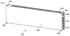
気流ディレクタモジュール202の一つの実施の形態の詳細を図3a−b、図4a−b、5a−bに示す。該気流ディレクタモジュールは、気流チャネルを形成するのに用いられる内部隔壁を複数有す外郭体300を有す。一つの実施の形態においては、この外郭体は略長方形の構成である。図3aの実施の形態においては、内部隔壁が隔壁302、304、306を含む。これら隔壁は一般的に、入口308、310、312から受け入れ、出口314、316、318から排出する気流を再方向付けするために曲線形をしている。
Details of one embodiment of the
気流ディレクタモジュール202同士を連結する連結機構の詳細を図4a、4bに示す。各気流ディレクタモジュール202は、四つの嵌合タブ窪み402と嵌合するように設計された四つの係合タブ400を含む。各係合タブ400は、一対の気流ディレクタモジュール202を連結する際に、対応する嵌合タブ窪み402と係合する突起404を含む。
Details of the coupling mechanism for coupling the
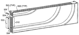
上述の通り、気流ディレクタ200の実施の形態は、選択的に全てあるいは一部の選択ダクトチャネルを遮蔽する機構を備えてもよい。一つの実施の形態においては図5a、5bに示すように、気流ディレクタ200が、ダクトチャネルの様々な入口・出口に配置される多数のスロット500を含んでいる。該スロットは一般的には多用途に使用されるように設計されてもよい。一側面によると、スロットは個々の気流ディレクタ202、引いては組み立て後の気流ディレクタ200の強度を増し、硬直機能を提供する。
As described above, embodiments of the
他の側面によると、該気流ディレクタの出口側にある該スロットは、該スロットから排出される気流を撹乱し、乱気という強制的気流による熱移動を高めるように構成されていてもよい。該スロットに加えて、他の手段を使用して気流ディレクタ出口から排出される気流を撹乱してもよい。例えば、隆起などが気流ディレクタモジュールの側壁に形成されていてもよい。 According to another aspect, the slot on the outlet side of the airflow director may be configured to disturb the airflow discharged from the slot and enhance heat transfer by forced airflow called turbulence. In addition to the slot, other means may be used to disturb the airflow discharged from the airflow director outlet. For example, a bulge or the like may be formed on the side wall of the airflow director module.
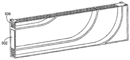
スロット500の設けられる他の目的は、スナップ嵌合する嵌合気流ブロックを設置するための係合手段を提供するためである。例えば、図5a、5bはそれぞれ気流ディレクタモジュール202に設置される前後の嵌合気流ブロック502、506の一例を示す。嵌合気流ブロック502は、該気流ブロックの各端に一以上の係合タブ504を含んでおり、この係合タブ504が気流ディレクタモジュールの対応するスロットをスナッピング動作により係合する。
Another purpose of the
一般的に、嵌合気流ブロックの幅は、該ブロックが遮蔽するように設計される入口あるいは出口の部分によって変化させることができる。例えば、嵌合ブロックは、一以上のスロットに亘る、入口あるいは出口の一部を遮蔽するのに用いられることができる。例えば、嵌合ブロック502は入口310の全体を遮蔽するように設計されており、一方、単一スロット用嵌合ブロック506は一つのスロットを遮蔽するように設計されている。加えて、ここで図示したスロットの幅と数は単に一例である。一般的にはスロットは均一な隙間を空けて設けられてもよいし、可変的な間隙を空けて設けられてもよい。さらに特定の入口あるいは出口の全てあるいは一部は、スロットがない一つの開口を含んでいてもよい。
In general, the width of the mating airflow block can vary depending on the portion of the inlet or outlet that the block is designed to shield. For example, the mating block can be used to shield a portion of the inlet or outlet over one or more slots. For example, the
システムの特定冷却要件によれば、様々なスロット500が、適切な大きさの嵌合気流ブロックを使用して選択的に遮蔽されてもよい。一般的には、空気を空気ディレクタ入口に押し込む際には嵌合気流ブロックを使用して入口を遮蔽する。空気が入口に引き込む際には(例えばシャーシの上端部に配置されるファンを使用して)、該嵌合気流ブロックの設置により、入口あるいは出口の選択部分を遮蔽するようにしてもよい。
Depending on the specific cooling requirements of the system, the
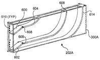
他の気流調整技術においては、一以上の前記気流ディレクタモジュールが調整可能な入口翼板を含む。例えば、調整可能な入口翼板600、602を含む気流ディレクタモジュール202Aの詳細を示す。各入口翼板は対応する隔壁604、606に旋回軸608を介して枢動可能に連結されている。一つの実施の形態においては、一対の対向するスタブ軸が一つの入口翼板内に形成されて旋回軸を形成しており、該対向するスタブ軸は、前記入口翼板が枢動可能に連結される該隔壁の嵌合窪みと係合する。他の実施の形態においては、軸が前記入口翼板と前記隔壁とに設けられた孔に挿入される。
In other airflow conditioning techniques, one or more of the airflow director modules include adjustable inlet vanes. For example, details of
一般的には、入口翼板の再配置を行うためには様々な仕組みの使用が可能である。図6a−cに図示された実施の形態においては、多数の戻り止め610が外郭体300Aに設けられている。嵌合突起は各入口翼板の片側(図示のとおり)あるいは両側(図示せず)に形成される。この突起、入口翼板、および回旋軸により、入口翼板を再配置して、選択された戻り止め610と係合することが可能となる。一般的には、調整可能な入口翼板を使用する気流ディレクタモジュールは、(この例では硬直目的で使用され得る)スロット500と類似したスロットを含んでも含まなくてもよい。
In general, various mechanisms can be used to reposition the inlet vanes. In the embodiment illustrated in FIGS. 6a-c, a number of
図6Cに示す通り、空洞612が外郭体300Aの裏面に形成されており、隔壁614が外郭体300Aの裏と前記外郭体の正面側に形成されたシェルフ616との間に形成されるようになっている。なお、気流ディレクタモジュール202に同様な構成を適用することもできる。
As shown in FIG. 6C, the
一般的に言って、気流ディレクタモジュール202と202Aは適切なプラスチックや金属で形成することができる。一つの実施の形態においては、プラスチック製の気流ディレクタモジュールを、当該技術分野で知られている通り、射出成形工程により形成する。他のプラスチック成形技術(真空形成法やロート成形法などを一例とするが、それに限定はされない)の使用も可能である。金属製の気流ディレクタモジュールは一般的に従来の金属形成技術(例としては、鋳造や溶造)を使用して形成することができる。
Generally speaking, the
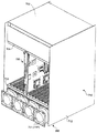
気流ディレクタ200をATCAシャーシに実装する例が図7a−cに示されている。明示の目的のため、ATCAシャーシの選択部分は図7a、7bからは省いている。略完全なシャーシを図7cに示す。
An example of mounting the
図7aは、上部プレナム702(図7c参照)の出口に向けて配置されている複数の軸ファン700を含むATCAシャーシ構成に対する気流を図示する。この構成は、気流ディレクタの出口側にわずかに真空状態を生成することで、空気を気流ディレクタ200の様々なダクトチャネルから引き込むために、「引き込み」構成と称することにする。一つの実施の形態においては、軸ファン700が多数の「ホットスワップ可能な」ファンを含むモジュラファンアセンブリの一部であり、これは欠陥の生じたファンを他のファンに対する電力消失なしに置き換え可能であることを意味している。
FIG. 7a illustrates airflow for an ATCA chassis configuration that includes a plurality of
図7bと7cにおいては、ATCAシャーシ710の下方正面にかけて軸ファン701の一組が追加されており、これにより気流ディレクタ200の入口側に空気が押し込まれる。この構成は、軸ファン701により空気を気流ディレクタ200の入口側に押し込むため、「押し込み」構成と称される。なお、軸ファン700、701の両方が設置される場合には、「押し込み」と「引き込み」の両方を組み合わせた構成が存在することになる。一つの実施の形態においては、軸ファン701は多数のホットスワップ可能なファンを含むモジュラファンアセンブリの一部であることがある。
7b and 7c, a set of
ここで図面に描かれている軸ファンに加えて、他の種類のファンを使用することもできる。例えば、軸性のファンの代わり、あるいはそれに加えて、一以上の遠心性ファンを使用することもできる。 In addition to the axial fan depicted here, other types of fans can be used. For example, one or more centrifugal fans can be used instead of or in addition to the axial fan.
ATCAシャーシ710は、ATCA前面基板708の設置を誘導するのに使用される上部/下部スロットガイド704、706を含む。一般的なATCA設置法を採用するATCAシャーシ一枚に対しては、一般的に多数のATCA前面基板が設置される。図7a−cには、明示の目的から、ATCA前面基板はたった一枚しか描かれていない。さらに、複数のATCA前面基板がバックプレーンに連結されるが、これも図7a−cには明示の目的から示していない。さらに、一般的に一以上のRTM(不図示)が前記バックプレーンには連結される。
The
図7aと7bにおいては、気流チャネル204、206を使用して気流をATCA前面基板上へと方向付けており、気流チャネル208を使用して気流をRTMへと方向付けている。さらに例えば図7b、7cの押し込み構成で図示されるような形で空気を様々な入口から押し込む際には、RTMを使用しないスロット用の入口312(例えば図3a参照)の全てあるいは一部を遮蔽することが望ましいであろう。図7aに例示したような引き込み構成に図示されるような、空気を前記気流ディレクタに引き込む実装例においては、RTMのないスロット用の出口318の全てあるいは一部を遮断してもよい。同様に、押し込み構成で空前面基板スロットに対しては(つまり、ATCA前面基板を受け入れるために空スロットとなっている場合)、入口308および310の全てあるいは一部を遮断して、引き込み構成においては出口314及び316の全てあるいは一部を遮断することが好ましい場合がある。
In FIGS. 7a and 7b,
図6a−cに示した気流ディレクタモジュール202Aを一以上含んだ気流ディレクタを使用する際にも、類似した種類の調整を行うことが可能である。この場合には、入口翼板600、602を調整して気流を好ましい形に再方向付けするようにすることも可能である。一般的には、押し込み/引き込み構成両方において、入口翼板の調整は共通している。
Similar types of adjustments can be made when using an airflow director that includes one or more of the
一つの実施の形態においては、気流ディレクタ200が、ATCAシャーシから簡単に除去可能、あるいはATCAシャーシで再調整、および再設置可能なアセンブリモジュールを有している。例えば、気流ディレクタはATCAシャーシの下部に連結されたシェルフ内に設置することができる。一つの実施の形態においては、ATCAシャーシ710の側面パネル712に、気流ディレクタアセンブリの第一気流ディレクタモジュール202の被覆プレートとしての機能をもたせて、前記第一気流ディレクタモジュールにダクトチャネルを形成することもある。
In one embodiment, the
さらに、気流ディレクタの入口側および/または出口側に一以上のフィルタ部材を配置することもできる。このようなフィルタ部材は、明示の目的から図面には示していない。 Furthermore, one or more filter members can be arranged on the inlet side and / or the outlet side of the airflow director. Such a filter member is not shown in the drawings for the purpose of clarity.
上述の、あるいは図示したATCAシャーシ実装の例に加えて、前述の実施の形態による一般原理や教示を、気流を一以上の回路基板上に方向付けるよう設計された様々な種類の冷却システムに実装することが可能である。非限定的なの実装例の一覧は、コンピュータサーバ(例えばブレードサーバ)、医療機器(例えば超音波機器)、及び電気通信装置(例えば、スイッチやルータなど)を含む。 In addition to the ATCA chassis implementation examples described above or illustrated, the general principles and teachings of the previous embodiments are implemented in various types of cooling systems designed to direct airflow onto one or more circuit boards. Is possible. A non-limiting list of implementations includes computer servers (eg, blade servers), medical devices (eg, ultrasound devices), and telecommunications devices (eg, switches, routers, etc.).
要約記載のものも含む、図示された本発明の実施の形態の上述の記述は、完全なものを意図しているわけでも、開示された特定の形態に本発明を限定することを意図したものでもない。ここでは本発明の特定の実施の形態や、例を例示目的で示したが、本発明の範囲内で様々な均等変形例が可能であることは、当業者には認識されるであろう。 The foregoing description of the illustrated embodiments of the invention, including the summary description, is intended to limit the invention to the particular forms disclosed, even though it is intended to be complete. not. While specific embodiments and examples of the invention have been illustrated herein for purposes of illustration, those skilled in the art will recognize that various equivalent variations are possible within the scope of the invention.
これら変形例を本発明に加えることは、上述の詳細な記述に基づき可能となる。以下の請求項に使用される用語は本発明を明細書並びに請求項に開示される特定の実施の形態に限定する目的で解釈されるべきではない。そうではなく、本発明の範囲はもっぱら以下の請求項から、請求項解釈の確立された原則に基づいて決定されるべきである。 These modifications can be made to the present invention based on the above detailed description. The terms used in the following claims should not be construed to limit the invention to the specific embodiments disclosed in the specification and the claims. Instead, the scope of the present invention should be determined solely from the following claims, based on established principles of claim interpretation.
Claims (30)
複数のダクトチャネルを有し、各ダクトチャネルは前記気流ディレクタの入口側に供給された気流を受け取る気流入口と、前記ダクトチャネルを通る気流を前記気流ディレクタの出口側で排出する気流出口とをもち、前記気流出口が少なくとも二つの列と段を含む、気流ディレクタ。 An airflow director,
A plurality of duct channels, each duct channel having an airflow inlet for receiving an airflow supplied to the inlet side of the airflow director and an airflow outlet for discharging the airflow passing through the duct channel on the outlet side of the airflow director; An airflow director, wherein the airflow outlet comprises at least two rows and steps.
プレナム手段を含み、前記プレナム手段には、
複数のダクトチャネルの各々が、前記プレナム手段の入口側に供給された気流を受け取る気流入口と、少なくとも二つの列と二つの段を持つ格子状に構成され、前記ダクトチャネルを通る気流を前記プレナム手段の出口側で排出する気流出口とをもつ複数のダクトチャネルと、
選択されたダクトチャネルを通る気流量を調整する手段とが含まれる、装置。 A device,
Including plenum means, said plenum means comprising:
Each of the plurality of duct channels is configured in a lattice shape having an air flow inlet for receiving an air flow supplied to the inlet side of the plenum means, and at least two rows and two stages, and the air flow passing through the duct channels is transmitted to the plenum. A plurality of duct channels having an air flow outlet for discharging on the outlet side of the means;
Means for regulating the air flow through the selected duct channel.
複数のブレードを保持するためのシャーシと、
前記シャーシの上部に連結される上部プレナムと、
前記シャーシの下部に連結される下部プレナムとを含むシステムであって、前記下部プレナムは複数のダクトチャネルを含み、各ダクトチャネルが、前記下部プレナムの入口側へ供給された気流を受け取るための気流入口と、少なくとも二つの列と二つの段を持つ格子状に構成され、前記ダクトチャネルを通る気流を前記下部プレナムの出口側から前記シャーシへ排出する気流出口とをもつ、システム。 A system,
A chassis to hold multiple blades;
An upper plenum coupled to the top of the chassis;
A lower plenum coupled to a lower portion of the chassis, wherein the lower plenum includes a plurality of duct channels, and each duct channel receives an air flow supplied to an inlet side of the lower plenum. A system having an inlet and an airflow outlet configured in a grid with at least two rows and two steps and exhausting airflow through the duct channel from the outlet side of the lower plenum to the chassis.
ブレードをそれぞれ設置可能な複数のスロットをもつモジュラブレードシャーシに下部プレナムを連結する工程であって、前記下部プレナムが複数のダクトチャネルを有し、各ダクトチャネルが、前記下部プレナムの入口側へ供給された気流を受け取るための気流入口と、少なくとも二つの列と二つの段を持つ格子状に構成され、前記ダクトチャネルを通る気流を前記下部プレナムの出口側から前記モジュラブレードシャーシへ排出する気流出口とをもつ工程と、
選択されたダクトチャネルを調整して、前記モジュラブレードシャーシの中の熱をあまり生成しない他の部分に比して、前記モジュラブレードシャーシの選択されたブレード上のホットスポット上にさらなる気流を方向付ける工程と、
前記複数のダクトチャネルに対して気流を押し込む、および引き込む、の少なくとも一方を行い、前記複数のブレードに対して気流を通す工程とを含む、方法。 A method,
Connecting a lower plenum to a modular blade chassis having a plurality of slots each capable of installing a blade, the lower plenum having a plurality of duct channels, each duct channel being fed to an inlet side of the lower plenum An airflow inlet configured to receive the generated airflow, and an airflow outlet configured to form a grid having at least two rows and two steps, and to discharge the airflow passing through the duct channel from the outlet side of the lower plenum to the modular blade chassis A process having
Adjust selected duct channels to direct additional airflow over hot spots on selected blades of the modular blade chassis relative to other parts that do not generate much heat in the modular blade chassis Process,
Performing at least one of pushing and drawing airflow into the plurality of duct channels and passing airflow through the plurality of blades.
Applications Claiming Priority (2)
| Application Number | Priority Date | Filing Date | Title |
|---|---|---|---|
| US10/875,968 US7259961B2 (en) | 2004-06-24 | 2004-06-24 | Reconfigurable airflow director for modular blade chassis |
| PCT/US2005/020576 WO2006011965A1 (en) | 2004-06-24 | 2005-06-10 | Reconfigurable airflow director for modular blade chassis |
Publications (1)
| Publication Number | Publication Date |
|---|---|
| JP2008501200A true JP2008501200A (en) | 2008-01-17 |
Family
ID=34972466
Family Applications (1)
| Application Number | Title | Priority Date | Filing Date |
|---|---|---|---|
| JP2007515696A Pending JP2008501200A (en) | 2004-06-24 | 2005-06-10 | Reconfigurable airflow director for modular blade chassis |
Country Status (9)
| Country | Link |
|---|---|
| US (1) | US7259961B2 (en) |
| EP (1) | EP1782161B1 (en) |
| JP (1) | JP2008501200A (en) |
| KR (1) | KR20070024637A (en) |
| CN (1) | CN1973252A (en) |
| AT (1) | ATE486312T1 (en) |
| DE (1) | DE602005024409D1 (en) |
| TW (1) | TWI278575B (en) |
| WO (1) | WO2006011965A1 (en) |
Cited By (3)
| Publication number | Priority date | Publication date | Assignee | Title |
|---|---|---|---|---|
| JP2009530755A (en) * | 2006-03-20 | 2009-08-27 | フレクストロニクス エイピー エルエルシー | Electronic device outer frame for enlarging the size of air inlet or air outlet, and method of using the same |
| WO2012090314A1 (en) * | 2010-12-28 | 2012-07-05 | 富士通株式会社 | Cooling unit, electronic device and guide member |
| JP2015099609A (en) * | 2010-09-20 | 2015-05-28 | アマゾン・テクノロジーズ・インコーポレーテッド | System with air flow under data storage device |
Families Citing this family (82)
| Publication number | Priority date | Publication date | Assignee | Title |
|---|---|---|---|---|
| US7259961B2 (en) | 2004-06-24 | 2007-08-21 | Intel Corporation | Reconfigurable airflow director for modular blade chassis |
| US20060004837A1 (en) * | 2004-06-30 | 2006-01-05 | Genovker Victoria V | Advanced switching peer-to-peer protocol |
| US7652891B2 (en) * | 2004-12-06 | 2010-01-26 | Radisys Corporation | Airflow control system |
| JP2007011931A (en) * | 2005-07-04 | 2007-01-18 | Hitachi Ltd | Memory control unit |
| JP2007047998A (en) * | 2005-08-09 | 2007-02-22 | Sony Corp | Electronic component cooling structure and information processor |
| US8189599B2 (en) * | 2005-08-23 | 2012-05-29 | Rpx Corporation | Omni-protocol engine for reconfigurable bit-stream processing in high-speed networks |
| JP4680726B2 (en) * | 2005-08-31 | 2011-05-11 | 本田技研工業株式会社 | Windproof device for small vehicles |
| US8107238B2 (en) | 2005-09-19 | 2012-01-31 | Chatsworth Products, Inc. | Ducted exhaust equipment enclosure |
| US7542287B2 (en) | 2005-09-19 | 2009-06-02 | Chatsworth Products, Inc. | Air diverter for directing air upwardly in an equipment enclosure |
| US11212928B2 (en) | 2005-09-19 | 2021-12-28 | Chatsworth Products, Inc. | Vertical exhaust duct for electronic equipment enclosure |
| US11259446B2 (en) | 2005-09-19 | 2022-02-22 | Chatsworth Products, Inc. | Vertical exhaust duct for electronic equipment enclosure |
| US7804685B2 (en) | 2005-09-19 | 2010-09-28 | Chatsworth Products, Inc. | Ducted exhaust equipment enclosure |
| US7420806B1 (en) * | 2005-11-22 | 2008-09-02 | Juniper Networks, Inc. | Airflow distribution through an electronic device |
| US7430117B2 (en) * | 2005-12-14 | 2008-09-30 | Flextronics Ap, Llc | Airflow system for electronics chassis |
| US8257155B2 (en) * | 2006-01-20 | 2012-09-04 | Chatsworth Products, Inc. | Selectively routing air within an electronic equipment enclosure |
| US20070171610A1 (en) * | 2006-01-20 | 2007-07-26 | Chatsworth Products, Inc. | Internal air duct |
| US7827442B2 (en) | 2006-01-23 | 2010-11-02 | Slt Logic Llc | Shelf management controller with hardware/software implemented dual redundant configuration |
| US7821790B2 (en) * | 2006-03-24 | 2010-10-26 | Slt Logic, Llc | Modular chassis providing scalable mechanical, electrical and environmental functionality for MicroTCA and Advanced TCA boards |
| US7355850B2 (en) * | 2006-03-31 | 2008-04-08 | National Instruments Corporation | Vented and ducted sub-rack support member |
| DE102006018709B3 (en) * | 2006-04-20 | 2007-10-11 | Nft Nanofiltertechnik Gmbh | Heat exchanger for cooling electronic component, has two stages arranged consecutively, where each stage has heat exchanging channel and guiding channels that are in flow connection with heat exchanging channels of next stages |
| US7701714B2 (en) * | 2006-05-26 | 2010-04-20 | Flextronics Ap, Llc | Liquid-air hybrid cooling in electronics equipment |
| WO2008003038A2 (en) * | 2006-06-29 | 2008-01-03 | Se2 Labs | Systems and methods for improved cooling of lelectrical components |
| US7508664B2 (en) * | 2006-07-28 | 2009-03-24 | International Business Machines Corporation | Mechanical assembly to support orthogonal airflow devices in a normal airflow slot of a server chassis |
| US20080024985A1 (en) * | 2006-07-31 | 2008-01-31 | Zong-Jui Lee | Computer casing with high heat dissipation efficiency |
| US7394654B2 (en) * | 2006-10-19 | 2008-07-01 | Cisco Technology, Inc. | Method and apparatus for providing thermal management in an electronic device |
| US7515411B2 (en) * | 2007-02-09 | 2009-04-07 | Lsi Corporation | Multi-fan airflow regulation for fan fail conditions |
| WO2008103927A2 (en) * | 2007-02-22 | 2008-08-28 | Tellabs Operations, Inc. | Apparatus and method for configuring a dual rack-mountable chassis |
| US20090036049A1 (en) * | 2007-07-30 | 2009-02-05 | Lodhia Ashwin V | Chassis having bottom and rear-provided air vents to enable airflow through the chassis |
| US20090061755A1 (en) * | 2007-08-28 | 2009-03-05 | Panduit Corp. | Intake Duct |
| CN101377705B (en) * | 2007-08-30 | 2012-08-29 | 鸿富锦精密工业(深圳)有限公司 | Computer |
| US20090109619A1 (en) * | 2007-10-25 | 2009-04-30 | Motorola, Inc. | Method apparatus for cooling system having an s-shaped air flow path for use in a chassis |
| US7751186B2 (en) * | 2007-10-29 | 2010-07-06 | Dell Products L.P. | Chassis having a bypass channel for air flow |
| US7907402B2 (en) * | 2007-11-09 | 2011-03-15 | Panduit Corp. | Cooling system |
| US10133320B2 (en) | 2008-02-14 | 2018-11-20 | Chatsworth Products, Inc. | Air directing device |
| CA2718733C (en) * | 2008-02-15 | 2015-05-26 | The Pnc Financial Services Group, Inc. | Systems and methods for computer equipment management |
| US20090260795A1 (en) * | 2008-04-16 | 2009-10-22 | Perazzo Thomas M | Active door array for cooling system |
| US7486511B1 (en) | 2008-06-04 | 2009-02-03 | International Business Machines Corporation | Passive rear door for controlled hot air exhaust |
| US7715182B2 (en) * | 2008-07-03 | 2010-05-11 | Lsi Corporation | Drive box |
| FR2934906B1 (en) * | 2008-08-05 | 2010-09-03 | Thales Sa | ON-BOARD CALCULATOR EQUIPPED WITH AN AUTONOMOUS AERAULIC COOLING DEVICE |
| US7633754B1 (en) * | 2008-08-27 | 2009-12-15 | Ciena Corporation | Air cooling system for an electronics rack |
| US7646602B1 (en) | 2008-08-29 | 2010-01-12 | Qlogic, Corporation | Apparatus and methods for cooling network switches |
| US7675750B1 (en) * | 2008-08-29 | 2010-03-09 | Qlogic, Corporation | Apparatus and methods for cooling networks switches |
| US10321601B2 (en) * | 2008-10-17 | 2019-06-11 | Artesyn Embedded Computing, Inc. | System and method for restricting airflow through a portion of an electronics enclosure |
| US8482917B2 (en) * | 2008-11-05 | 2013-07-09 | Arista Networks, Inc. | Network switch cooling system |
| GB2464839B (en) * | 2008-12-03 | 2012-11-28 | Ibm | Controllable air inlet duct for server racks |
| US20100159816A1 (en) * | 2008-12-23 | 2010-06-24 | International Business Machines Corporation | Converging segments cooling |
| EP2205054A1 (en) * | 2009-01-05 | 2010-07-07 | Chatsworth Product, INC. | Electronic equipment enclosure with side-to-side airflow control system |
| US20110228475A1 (en) * | 2010-03-17 | 2011-09-22 | International Business Machines Corporation | Enclosure with concurrently maintainable field replaceable units |
| CN102238850A (en) * | 2010-04-29 | 2011-11-09 | 鸿富锦精密工业(深圳)有限公司 | Server combination |
| US8653363B2 (en) | 2010-06-01 | 2014-02-18 | Chatsworth Products, Inc. | Magnetic filler panel for use in airflow control system in electronic equipment enclosure |
| JP5829010B2 (en) * | 2010-06-24 | 2015-12-09 | 富士通株式会社 | Case unit cooling structure |
| US8446725B2 (en) * | 2010-08-05 | 2013-05-21 | Alcatel Lucent | Airflow control in an electronic chassis |
| WO2013000119A1 (en) * | 2011-06-28 | 2013-01-03 | Telefonaktiebolaget L M Ericsson (Publ) | Electronic device with heat-dissipating structure |
| TW201309179A (en) * | 2011-08-04 | 2013-02-16 | Wistron Corp | Airflow adjusting device and blade server |
| US8780551B2 (en) * | 2011-12-21 | 2014-07-15 | Brocade Communications Systems, Inc. | Blade and air deflector in a plenum |
| US9408330B2 (en) * | 2012-04-18 | 2016-08-02 | International Business Machines Coporation | Apparatus to cool a computing device |
| US9839155B2 (en) | 2012-05-16 | 2017-12-05 | Panduit Corp. | Thermal ducting system |
| TW201408179A (en) * | 2012-08-01 | 2014-02-16 | Hon Hai Prec Ind Co Ltd | Airflow guiding member and electronic device having the same |
| US20140073234A1 (en) * | 2012-09-11 | 2014-03-13 | International Business Machines Corporation | Chassis with an airflow adjustment |
| US9204576B2 (en) * | 2012-09-14 | 2015-12-01 | Cisco Technolgy, Inc. | Apparatus, system, and method for configuring a system of electronic chassis |
| CN103717033A (en) * | 2012-09-29 | 2014-04-09 | 华为技术有限公司 | Cabinet and temperature control device |
| TW201442610A (en) * | 2013-04-30 | 2014-11-01 | Hon Hai Prec Ind Co Ltd | Chassis |
| US9203782B2 (en) | 2013-11-20 | 2015-12-01 | Ciena Corporation | High density networking shelf and system |
| DE102014201483B4 (en) * | 2014-01-28 | 2016-04-07 | Wago Verwaltungsgesellschaft Mbh | Cuboid housing for an electronics module, electronic module and arrangement for cooling at least one electronic module |
| US9788461B2 (en) * | 2014-07-30 | 2017-10-10 | Ciena Corporation | Airflow divider for balancing airflow in a modular chassis system |
| US10451300B2 (en) * | 2015-01-23 | 2019-10-22 | Tata Consultancy Services Limited | System and method for facilitating homogenized distribution of airflow in a data center |
| CN104754894B (en) * | 2015-04-09 | 2018-05-04 | 北京百度网讯科技有限公司 | Server cabinet |
| WO2016167805A1 (en) | 2015-04-17 | 2016-10-20 | Hewlett-Packard Development Company, L.P. | Shell ductings for cool air delivery |
| US9603289B1 (en) * | 2016-01-14 | 2017-03-21 | Ciena Corporation | Chassis arrangement systems and methods for dual depth cards and dual depth faraday cages |
| US10212846B2 (en) * | 2016-05-12 | 2019-02-19 | Facebook, Inc. | Data storage server drawer |
| FR3062771B1 (en) * | 2017-02-08 | 2019-04-05 | Alstom Transport Technologies | FORCED CONVECTION COOLED ELECTRONIC MODULE WITH AIR FLOW DISTRIBUTION GRID |
| JP6769356B2 (en) * | 2017-03-13 | 2020-10-14 | 富士通株式会社 | Information processing device |
| US11019753B2 (en) | 2017-06-27 | 2021-05-25 | Microsoft Technology Licensing, Llc | Cooling electronic devices within a data center |
| US10219405B2 (en) * | 2017-07-10 | 2019-02-26 | National Instruments Corporation | Airflow straightener in an electronics chassis |
| USD865755S1 (en) * | 2018-01-12 | 2019-11-05 | Guohui Yang | Computer main processor box |
| US20190357390A1 (en) * | 2018-05-18 | 2019-11-21 | Nokia Solutions And Networks Oy | Fan apparatuses for chassis airflow |
| US11212945B2 (en) | 2019-05-31 | 2021-12-28 | Hewlett Packard Enterprise Development Lp | System airflow variable configuration |
| US10952353B1 (en) * | 2019-08-21 | 2021-03-16 | Schneider Electric It Corporation | Thermal buffering module for equipment rack |
| US11980009B2 (en) | 2019-10-15 | 2024-05-07 | Ciena Corporation | Liquid cooling high-density pluggable modules for a network element |
| US11184995B2 (en) | 2019-11-01 | 2021-11-23 | Ciena Corporation | High-density network element cooling via unequipped pluggable optical module cages |
| US11112573B2 (en) | 2019-11-01 | 2021-09-07 | Ciena Corporation | Cooling multiple high-density network pluggable optical modules using a shared heat exchanger |
| US11659692B2 (en) * | 2019-12-20 | 2023-05-23 | Microsoft Technology Licensing, Llc | Rack assembly for vertical airflow cooled devices |
Citations (9)
| Publication number | Priority date | Publication date | Assignee | Title |
|---|---|---|---|---|
| JPS57186091U (en) * | 1981-05-19 | 1982-11-26 | ||
| JPH0361389U (en) * | 1989-10-20 | 1991-06-17 | ||
| JPH04252098A (en) * | 1991-01-28 | 1992-09-08 | Fujitsu Ltd | Structure for cooling electronic device |
| US5409419A (en) * | 1992-04-08 | 1995-04-25 | Schroff Gmbh | Ventilator insert |
| JPH0832279A (en) * | 1994-07-20 | 1996-02-02 | Toshiba Corp | Housing structure for electronic apparatus |
| JPH09167896A (en) * | 1995-12-15 | 1997-06-24 | Mitsubishi Electric Corp | Electronic device container and its cooling method |
| JP2001024373A (en) * | 1999-07-07 | 2001-01-26 | Sony Corp | Electrical equipment with fan device |
| JP2001257495A (en) * | 2000-03-10 | 2001-09-21 | Oki Electric Ind Co Ltd | Cooling structure for housing |
| JP2003249786A (en) * | 2002-02-25 | 2003-09-05 | Nec Corp | Dewing preventing structure of electronic equipment and dewing preventing method |
Family Cites Families (42)
| Publication number | Priority date | Publication date | Assignee | Title |
|---|---|---|---|---|
| US2894728A (en) * | 1957-02-06 | 1959-07-14 | Trane Co | Multi-zone air conditioning unit |
| US3387648A (en) * | 1967-02-23 | 1968-06-11 | Navy Usa | Cabinet enclosed recirculation cooling system carried on extensible chassis mountingelectronic modules |
| US3592260A (en) * | 1969-12-05 | 1971-07-13 | Espey Mfg & Electronics Corp | Heat exchanger with inner guide strip |
| US3874444A (en) * | 1973-12-03 | 1975-04-01 | Gte Automatic Electric Lab Inc | Duo-baffle air separator apparatus |
| US3917370A (en) * | 1974-08-29 | 1975-11-04 | Amp Inc | Interconnect device for use in closed fluid circulating systems |
| DE2651015C2 (en) | 1976-11-09 | 1980-09-04 | Honeywell-Elac-Nautik Gmbh, 2300 Kiel | Chassis for an electrical power amplifier |
| US4261519A (en) * | 1978-12-20 | 1981-04-14 | Honeywell Information Systems Inc. | Air distribution system |
| US4648007A (en) * | 1985-10-28 | 1987-03-03 | Gte Communications Systems Corporation | Cooling module for electronic equipment |
| JPH0770853B2 (en) * | 1987-01-21 | 1995-07-31 | 株式会社日立製作所 | Electronic device cooling system |
| US5202816A (en) * | 1991-05-20 | 1993-04-13 | Dewilde Mark A | High density circuit board chassis cooling system |
| FR2699422B1 (en) | 1992-12-17 | 1997-01-10 | Transrack Sa | VENTILATION BOX FOR ELECTRIC OR ELECTRONIC CABINETS. |
| US5676199A (en) * | 1993-07-23 | 1997-10-14 | Lee; Richard M. L. | Thermostat controlled cooler for a CPU |
| US6011688A (en) | 1997-06-04 | 2000-01-04 | Hewlett Packard Co. | Compact apparatus for cooling a plurality of circuit packs arranged with a cage |
| US6042474A (en) * | 1997-06-04 | 2000-03-28 | Lsi Logic Corporation | Compact ventilation unit with exhaust ports for electronic apparatus |
| JP4080593B2 (en) * | 1998-05-11 | 2008-04-23 | 浜松ホトニクス株式会社 | Optical sensor |
| US6381147B1 (en) * | 1998-05-15 | 2002-04-30 | Hybricon Corporation | Card guide including air deflector means |
| US5995368A (en) * | 1998-10-20 | 1999-11-30 | Nortel Networks Corporation | Air flow distribution device for shelf-based circuit cards |
| US6289678B1 (en) * | 1998-12-03 | 2001-09-18 | Phoenix Group, Inc. | Environmental system for rugged disk drive |
| US6094919A (en) * | 1999-01-04 | 2000-08-01 | Intel Corporation | Package with integrated thermoelectric module for cooling of integrated circuits |
| US6185109B1 (en) * | 1999-02-26 | 2001-02-06 | 3Com Corporation | Electronic chassis apparatus and method |
| US6326597B1 (en) * | 1999-04-15 | 2001-12-04 | Applied Materials, Inc. | Temperature control system for process chamber |
| US6252770B1 (en) * | 2000-08-02 | 2001-06-26 | Ming-Chuan Yu | Electronic apparatus cooling device |
| US6512672B1 (en) * | 2000-12-29 | 2003-01-28 | Cisco Technology, Inc. | Modular air flow distribution system |
| US6882533B2 (en) * | 2001-02-22 | 2005-04-19 | Hewlett-Packard Development Company, L.P. | Thermal connector for cooling electronics |
| US6616469B2 (en) * | 2001-03-12 | 2003-09-09 | Tyco Electronics Logistics Ag | Electrical and fluid interconnect |
| US6646879B2 (en) * | 2001-05-16 | 2003-11-11 | Cray Inc. | Spray evaporative cooling system and method |
| US6506111B2 (en) * | 2001-05-16 | 2003-01-14 | Sanmina-Sci Corporation | Cooling airflow distribution device |
| US6646878B2 (en) * | 2001-07-16 | 2003-11-11 | I-Bus Corporation | Fail safe cooling system |
| US20030062150A1 (en) * | 2001-09-25 | 2003-04-03 | Melissa Sweitzer | Temperature/strain control of fatigue vulnerable devices used in electronic circuits |
| CA2358019A1 (en) * | 2001-09-27 | 2003-03-27 | Alcatel Canada Inc. | System and method for configuring a network element |
| US20040008483A1 (en) * | 2002-07-13 | 2004-01-15 | Kioan Cheon | Water cooling type cooling system for electronic device |
| US6807056B2 (en) * | 2002-09-24 | 2004-10-19 | Hitachi, Ltd. | Electronic equipment |
| US6754076B2 (en) * | 2002-10-30 | 2004-06-22 | International Business Machines Corporation | Stackable liquid cooling pump |
| TW586653U (en) * | 2003-04-18 | 2004-05-01 | Delta Electronics Inc | Heat dissipation module with twin centrifugal fans |
| US7097495B2 (en) * | 2003-07-14 | 2006-08-29 | Tribotek, Inc. | System and methods for connecting electrical components |
| US6912131B2 (en) * | 2003-08-27 | 2005-06-28 | Lucent Technologies Inc. | Electronic components card air deflector |
| US6880345B1 (en) * | 2003-11-04 | 2005-04-19 | Intel Corporation | Cooling system for an electronic component |
| JP2005228237A (en) * | 2004-02-16 | 2005-08-25 | Hitachi Ltd | Liquid cooled system and electronic equipment provided therewith |
| US20050241803A1 (en) * | 2004-04-29 | 2005-11-03 | Hewlett-Packard Development Company, L.P. | Liquid cooling loop using tubing and bellows for stress isolation and tolerance variation |
| US8430156B2 (en) * | 2004-04-29 | 2013-04-30 | Hewlett-Packard Development Company, L.P. | Liquid loop with multiple pump assembly |
| US7259961B2 (en) | 2004-06-24 | 2007-08-21 | Intel Corporation | Reconfigurable airflow director for modular blade chassis |
| US6935868B1 (en) * | 2004-06-29 | 2005-08-30 | Intel Corporation | Adjustable-width, dual-connector card module |
-
2004
- 2004-06-24 US US10/875,968 patent/US7259961B2/en active Active
-
2005
- 2005-06-10 AT AT05760516T patent/ATE486312T1/en not_active IP Right Cessation
- 2005-06-10 CN CNA200580020527XA patent/CN1973252A/en active Pending
- 2005-06-10 EP EP05760516A patent/EP1782161B1/en not_active Not-in-force
- 2005-06-10 KR KR1020067027125A patent/KR20070024637A/en not_active Application Discontinuation
- 2005-06-10 WO PCT/US2005/020576 patent/WO2006011965A1/en active Application Filing
- 2005-06-10 JP JP2007515696A patent/JP2008501200A/en active Pending
- 2005-06-10 DE DE602005024409T patent/DE602005024409D1/en active Active
- 2005-06-21 TW TW094120581A patent/TWI278575B/en not_active IP Right Cessation
Patent Citations (9)
| Publication number | Priority date | Publication date | Assignee | Title |
|---|---|---|---|---|
| JPS57186091U (en) * | 1981-05-19 | 1982-11-26 | ||
| JPH0361389U (en) * | 1989-10-20 | 1991-06-17 | ||
| JPH04252098A (en) * | 1991-01-28 | 1992-09-08 | Fujitsu Ltd | Structure for cooling electronic device |
| US5409419A (en) * | 1992-04-08 | 1995-04-25 | Schroff Gmbh | Ventilator insert |
| JPH0832279A (en) * | 1994-07-20 | 1996-02-02 | Toshiba Corp | Housing structure for electronic apparatus |
| JPH09167896A (en) * | 1995-12-15 | 1997-06-24 | Mitsubishi Electric Corp | Electronic device container and its cooling method |
| JP2001024373A (en) * | 1999-07-07 | 2001-01-26 | Sony Corp | Electrical equipment with fan device |
| JP2001257495A (en) * | 2000-03-10 | 2001-09-21 | Oki Electric Ind Co Ltd | Cooling structure for housing |
| JP2003249786A (en) * | 2002-02-25 | 2003-09-05 | Nec Corp | Dewing preventing structure of electronic equipment and dewing preventing method |
Cited By (4)
| Publication number | Priority date | Publication date | Assignee | Title |
|---|---|---|---|---|
| JP2009530755A (en) * | 2006-03-20 | 2009-08-27 | フレクストロニクス エイピー エルエルシー | Electronic device outer frame for enlarging the size of air inlet or air outlet, and method of using the same |
| JP2015099609A (en) * | 2010-09-20 | 2015-05-28 | アマゾン・テクノロジーズ・インコーポレーテッド | System with air flow under data storage device |
| WO2012090314A1 (en) * | 2010-12-28 | 2012-07-05 | 富士通株式会社 | Cooling unit, electronic device and guide member |
| US9237675B2 (en) | 2010-12-28 | 2016-01-12 | Fujitsu Limited | Cooling unit, electronic apparatus, and guide member |
Also Published As
| Publication number | Publication date |
|---|---|
| TWI278575B (en) | 2007-04-11 |
| EP1782161A1 (en) | 2007-05-09 |
| ATE486312T1 (en) | 2010-11-15 |
| US20050286222A1 (en) | 2005-12-29 |
| EP1782161B1 (en) | 2010-10-27 |
| WO2006011965A1 (en) | 2006-02-02 |
| US7259961B2 (en) | 2007-08-21 |
| TW200604444A (en) | 2006-02-01 |
| KR20070024637A (en) | 2007-03-02 |
| CN1973252A (en) | 2007-05-30 |
| DE602005024409D1 (en) | 2010-12-09 |
Similar Documents
| Publication | Publication Date | Title |
|---|---|---|
| JP2008501200A (en) | Reconfigurable airflow director for modular blade chassis | |
| US7372695B2 (en) | Directional fan assembly | |
| US7430117B2 (en) | Airflow system for electronics chassis | |
| US7209351B2 (en) | Telecom equipment chassis using modular air cooling system | |
| US7508663B2 (en) | Computer rack cooling system with variable airflow impedance | |
| US6525935B2 (en) | Low profile highly accessible computer enclosure with plenum for cooling high power processors | |
| US7764511B2 (en) | Multidirectional configurable architecture for multi-processor system | |
| US10271460B2 (en) | Server system | |
| US20080043405A1 (en) | Chassis partition architecture for multi-processor system | |
| WO2011045863A1 (en) | Electronic device and casing for electronic device | |
| JP2006120154A (en) | System for airflow management in electronic enclosure, central electronics complex and airflow management system (system for airflow management in electronic enclosure) | |
| US10013033B2 (en) | Electronic assembly with thermal channel and method of manufacture thereof | |
| WO2000079854A1 (en) | Apparatus and method for mounting a processor circuit board on a system mother board | |
| US6259600B1 (en) | Apparatus and method for cooling a processor circuit board | |
| JP2004336030A (en) | Partition for circuit card facilitating heat management in electronic system | |
| US20150124405A1 (en) | Electronic component cooling system and method | |
| US7183500B2 (en) | Electromagnetic interference (EMI) filter with passive noise cancellation | |
| JP5337723B2 (en) | Electronic equipment | |
| TWI633415B (en) | Electronic assembly with thermal channel and method of manufacture thereof | |
| CN214592539U (en) | Air guide channel assembly, component set and server comprising air guide channel assembly | |
| CN115390627A (en) | Server, server group and expansion method thereof | |
| JP2006521620A (en) | Computer system and method configured to improve cooling | |
| KR200179748Y1 (en) | Optical cable distributing shelf structure of rack for switching system |
Legal Events
| Date | Code | Title | Description |
|---|---|---|---|
| A977 | Report on retrieval |
Free format text: JAPANESE INTERMEDIATE CODE: A971007 Effective date: 20090713 |
|
| A131 | Notification of reasons for refusal |
Free format text: JAPANESE INTERMEDIATE CODE: A131 Effective date: 20090818 |
|
| A02 | Decision of refusal |
Free format text: JAPANESE INTERMEDIATE CODE: A02 Effective date: 20100202 |