JP2008287898A - Connector - Google Patents
Connector Download PDFInfo
- Publication number
- JP2008287898A JP2008287898A JP2007128873A JP2007128873A JP2008287898A JP 2008287898 A JP2008287898 A JP 2008287898A JP 2007128873 A JP2007128873 A JP 2007128873A JP 2007128873 A JP2007128873 A JP 2007128873A JP 2008287898 A JP2008287898 A JP 2008287898A
- Authority
- JP
- Japan
- Prior art keywords
- housing
- locking
- claw
- rear holder
- temporary
- Prior art date
- Legal status (The legal status is an assumption and is not a legal conclusion. Google has not performed a legal analysis and makes no representation as to the accuracy of the status listed.)
- Pending
Links
Images


Classifications
-
- H—ELECTRICITY
- H01—ELECTRIC ELEMENTS
- H01R—ELECTRICALLY-CONDUCTIVE CONNECTIONS; STRUCTURAL ASSOCIATIONS OF A PLURALITY OF MUTUALLY-INSULATED ELECTRICAL CONNECTING ELEMENTS; COUPLING DEVICES; CURRENT COLLECTORS
- H01R13/00—Details of coupling devices of the kinds covered by groups H01R12/70 or H01R24/00 - H01R33/00
- H01R13/40—Securing contact members in or to a base or case; Insulating of contact members
- H01R13/42—Securing in a demountable manner
- H01R13/436—Securing a plurality of contact members by one locking piece or operation
- H01R13/4367—Insertion of locking piece from the rear
- H01R13/4368—Insertion of locking piece from the rear comprising a temporary and a final locking position
-
- H—ELECTRICITY
- H01—ELECTRIC ELEMENTS
- H01R—ELECTRICALLY-CONDUCTIVE CONNECTIONS; STRUCTURAL ASSOCIATIONS OF A PLURALITY OF MUTUALLY-INSULATED ELECTRICAL CONNECTING ELEMENTS; COUPLING DEVICES; CURRENT COLLECTORS
- H01R13/00—Details of coupling devices of the kinds covered by groups H01R12/70 or H01R24/00 - H01R33/00
- H01R13/40—Securing contact members in or to a base or case; Insulating of contact members
- H01R13/42—Securing in a demountable manner
- H01R13/422—Securing in resilient one-piece base or case, e.g. by friction; One-piece base or case formed with resilient locking means
- H01R13/4223—Securing in resilient one-piece base or case, e.g. by friction; One-piece base or case formed with resilient locking means comprising integral flexible contact retaining fingers
- H01R13/4226—Securing in resilient one-piece base or case, e.g. by friction; One-piece base or case formed with resilient locking means comprising integral flexible contact retaining fingers comprising two or more integral flexible retaining fingers acting on a single contact
Landscapes
- Connector Housings Or Holding Contact Members (AREA)
- Details Of Connecting Devices For Male And Female Coupling (AREA)
Abstract
Description
本発明は、例えば自動車等の電気配線に使用され、ハウジングに収容した接続端子を係止するためのリアホルダを備えたコネクタに関するものである。 The present invention relates to a connector provided with a rear holder for locking a connection terminal accommodated in a housing, for example, used for electric wiring of an automobile or the like.
従来のこの種のコネクタでは、例えば特許文献1のように、ハウジングの後部にリアホルダが前後動自在に係合され、リアホルダはハウジングに中間まで挿入された仮係止位置と、十分に押し込まれた本係止位置とで係合するようにした場合がある。ハウジングに接続端子を収容した後にリアホルダを取り付けるのでは、接続端子に接続した電線を個々にリアホルダを挿通しなければならない。しかし、リアホルダを仮係止状態にして、接続端子と電線とをリアホルダを通過させながらハウジングに挿入すると、能率的な組立が可能となる。 In this type of conventional connector, for example, as disclosed in Patent Document 1, the rear holder is engaged with the rear portion of the housing so as to be movable back and forth, and the rear holder is sufficiently pushed into the temporary locking position inserted to the middle of the housing. There is a case where the main locking position is engaged. When the rear holder is attached after the connection terminal is accommodated in the housing, the rear holder must be individually inserted through the electric wires connected to the connection terminal. However, when the rear holder is temporarily locked and the connection terminal and the electric wire are inserted into the housing while passing through the rear holder, efficient assembly becomes possible.
また、収容された接続端子を係止する係止ランスをハウジングの後部に取り付け、ハウジングと別体のリアホルダに設けることもある。この場合には、係止ランスの成形が容易となると共に、比較的耐久性を有し高価な材質を要する係止ランスを、合成樹脂が小容量で済むリアホルダに設けるため、全体として安価となる。 In addition, a locking lance for locking the received connection terminal may be attached to the rear portion of the housing and provided in a rear holder separate from the housing. In this case, the locking lance can be easily molded, and the locking lance that is relatively durable and requires an expensive material is provided on the rear holder that requires a small amount of synthetic resin, so that the overall cost is low. .
この従来のコネクタをハーネスメーカに納入する際には、リアホルダをハウジングに対し仮係止状態に組立てて納入し、ハーネスメーカにおいて、ハウジング内にリアホルダを経て接続端子を挿着する作業を行うことがある。 When delivering this conventional connector to a harness manufacturer, the rear holder is assembled and delivered in a temporarily locked state to the housing, and the harness manufacturer performs the work of inserting the connection terminal into the housing via the rear holder. is there.
しかし、ハウジングを運搬する途中で、リアホルダが不時の力で前方に押され、仮係止位置から本係止位置に移動してしまうという問題点がある。この場合に、リアホルダを仮係止位置に戻さなければならず、極めて面倒な作業が余儀なくされる。 However, there is a problem in that the rear holder is pushed forward by an unreasonable force during the transportation of the housing and moves from the temporary locking position to the main locking position. In this case, the rear holder must be returned to the temporary locking position, and an extremely troublesome work is forced.
本発明の目的は、このような問題点を解消し、ハウジングとリアホルダとの安定した仮係止状態を確保できるコネクタを提供することにある。 An object of the present invention is to provide a connector that can solve such problems and ensure a stable temporary locking state between a housing and a rear holder.
上記目的を達成するための本発明に係るコネクタの技術的特徴は、接続端子を収容するハウジングと、該ハウジングの後部に係合し前記接続端子の一部を係止する係止ランスを備えたリアホルダとから成り、該リアホルダは前記ハウジングに対し仮係止位置を経て本係止位置に係止可能とし、前記リアホルダは前記ハウジングに対し仮係止用錠止部と本係止用錠止部とを有し、前記仮係止用錠止部は前後方向に間隔をおいて前部爪と後部爪とを配置し、前記仮係止位置において、前記ハウジングの条片状の対位仮錠止部を前記前部爪と後部爪とにより挟み込んで仮係止することにある。 The technical feature of the connector according to the present invention for achieving the above object includes a housing that accommodates a connection terminal, and a locking lance that engages with a rear portion of the housing and locks a part of the connection terminal. A rear holder, and the rear holder can be locked to the main locking position via the temporary locking position with respect to the housing, and the rear holder is temporarily locked with the locking portion and the locking lock portion with respect to the housing. The temporary locking lock portion has a front claw and a rear claw spaced apart in the front-rear direction, and in the temporary locking position, a strip-like counter temporary lock of the housing The stop portion is sandwiched between the front claw and the rear claw and temporarily locked.
本発明に係るコネクタによれば、リアホルダは仮係止用錠止部によってハウジングに対し前後動が規制され、仮係止状態を維持することができる。 According to the connector of the present invention, the rear holder is restricted from moving back and forth with respect to the housing by the temporary locking lock part, and can maintain the temporary locked state.
本発明を図示の実施例に基づいて詳細に説明する。
図1はハウジングの平面図、図2は側面図、図3はリアホルダの平面図、図4は側面図、図5は正面図である。接続端子を収容するハウジング11の後部にリアホルダ12を係合し、リアホルダ12によりハウジング11内に収容された接続端子の後抜けを防止するようにしている。
The present invention will be described in detail based on the embodiments shown in the drawings.
1 is a plan view of the housing, FIG. 2 is a side view, FIG. 3 is a plan view of the rear holder, FIG. 4 is a side view, and FIG. 5 is a front view. The
図6に示す接続端子13はハウジング11内に収容されて使用される。この接続端子13は導電金属板により形成され、相手側端子を接続する角筒状の端子接続部14と、電線15の芯線を固定する芯線固定部16と、電線15の被覆を固定する被覆固定部17とが前方から順次に設けられている。なお、被覆固定部17の後部には、必要に応じて防止シール材18が挿着される。
The
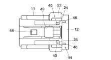
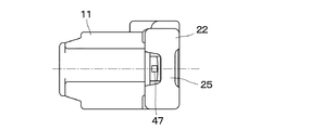
ハウジング11とリアホルダ12は、それぞれ電気絶縁性を有する合成樹脂材料を成型することにより製造されている。ハウジング11は略角筒形に成型され、内部に例えば上段2列、下段4列の計6個の接続端子13を個々に収容する端子収容室21が設けられている。なお、図面においては、端子収容室21の区画等、内部構造等の図示は省略している。
The
また、ハウジング11の後部には、端子収容室21の囲りの角筒よりも大径の角筒状のリアホルダ収納部22が設けられている。このリアホルダ収納部22の上下の壁部23a、23bには、接続端子の挿入方向と直交する方向に2個ずつの条片状の仮係止用錠止片24が形成され、左右の壁部23c、23dには、同様に接続端子の挿入方向と直交する方向に1個ずつの条片状の本係止用錠止片25が形成されている。
In addition, at the rear part of the
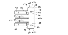
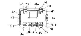
一方、リアホルダ12にはハウジング11の後部のリアホルダ収納部22に嵌合する角筒状のホルダ本体部41が設けられ、ホルダ本体部41の前端部には、端子収容室21内に収容された接続端子13の端子接続部14を個々に係止するための計6個の係止ランス42が、前方に向けて突設されている。また、ホルダ本体部41の後部には、電線15付きの接続端子13をそれぞれ挿通するための図示しない5個の孔部が設けられている。
On the other hand, the
ホルダ本体部41の上下の壁部41a、41bの2個所ずつには、ハウジング11の仮係止用錠止片24に係合する仮係止用錠止部44が設けられている。仮係止用錠止部44はそれぞれ2個一対の前部爪45と後部爪46とから成り、これらの前部爪45と後部爪46は前後にずれて位置していると共に、成型の関係で左右にもずれて配置されている。前部爪45と後部爪46との前後方向の間隔は、ハウジング11の仮係止用錠止片24を挟み込む間隔とされている。
A temporary
前部爪45の前端は前方から後方に向けて立ち上る傾斜面とされ、後端は垂直な壁面とされている。また、後部爪46は前部爪45よりも低く、その前端は垂直に立ち上ると共に、本係止位置への押し込みを容易とするために頂部を丸くした壁面とされ、後部は頂部から下方に傾斜する傾斜面とされている。
The front end of the
更に、リアホルダ12のホルダ本体部41の左右の壁部41c、41dには、ハウジング11の本係止用錠止片25と係合するための本係止用錠止爪47が1個ずつ設けられている。本係止用錠止爪47の前部は前方から立ち上る傾斜面47aとされ、後部は垂直に立ち上る壁面47bとされている。
Further, the left and
ハウジング11の本係止用錠止片25のリアホルダ12側の面は、リアホルダ12の本係止用錠止爪47の傾斜面47aと一致する傾斜角とされている。なお、ハウジング11の上面に設けられたレバーには相手側ハウジングとロックするためのロック爪48が設けられ、ロック解除に際しては、押圧部49を押し込むことにより、ロック爪48を相手側ハウジングから解除するようになっている。
The surface on the
このような構成を有するハウジング11とリアホルダ12とは、図7〜図10に示すように、リアホルダ12がハウジング11の後部に中間まで挿入された仮係止位置と、更に押し込むことによる図11〜図14に示すように、リアホルダ12がハウジング11に対して十分に押し込まれた本係止位置とで係合される。なお、図7、図11は平面図、図8、図12は側面図、図9、図13は平面方向から見た断面図、図10、図14は側面方向から見た断面図を示している。
As shown in FIGS. 7 to 10, the
即ち、図7〜図10に示すリアホルダ12の仮係止位置では、リアホルダ12の仮係止用錠止部44の前部爪45はハウジング11の仮係止用錠止片24を潜り抜け、後部爪46とにより仮係止用錠止片24を挟み込む。このとき、リアホルダ12の本係止用錠止爪47の前部の傾斜面47aは、ハウジング11の本係止用錠止片25のリアホルダ21側の面に当接している。
That is, in the temporary locking position of the
この仮係止状態では、本係止用錠止爪47は本係止用錠止片25に当接し、容易にこの仮係止状態は崩れることはなく、必要に応じてこの仮係止状態で運搬等がなされる。
In this temporarily locked state, the final
電線15付の接続端子13は、仮係止位置にあるときのリアホルダ12の孔部43を経てハウジング11の端子収容室21に挿入される。このとき、接続端子13の端子接続部14が係止ランス42の上面を外側に押圧して撓ませながら、接続端子13の端子接続部14が係止ランス42を潜り抜けると、係止ランス42が元の位置に復元し、端子接続部14の後端部を係止する。
The
全ての端子収容室21の仮の位置に接続端子13を挿入してから、リアホルダ12をハウジング11の前方に向けて強く押し込むと、リアホルダ12の仮係止用錠止部44の後部爪46はハウジング11の仮係止用錠止片24を潜り抜け、同時にリアホルダ12の本係止用錠止爪47はハウジング11の本係止用錠止片25を潜り抜けて、リアホルダ12はハウジング11のリアホルダ収納部22内に完全に納まり、ハウジング11に対し図11〜図14に示すような本係止位置となる。このときリアホルダ12はハウジング11の本係止用錠止片25に対し、本係止用錠止爪47により本係止位置が確保される。
When the
リアホルダ12が仮係止位置から本係止位置に至る過程で、接続端子13はリアホルダ12の係止ランス42により押し込まれ、端子収容室21内の正規の位置まで移動され、そのまま係止ランス42により係止がなされる。
In the process in which the
11 ハウジング
12 リアホルダ
13 接続端子
21 端子収容室
22 リアホルダ収納部
23 壁部
24 仮係止用錠止片
25 本係止用錠止片
41 ホルダ本体部
42 係止ランス
44 仮係止用錠止爪
45 前部爪
46 後部爪
47 本係止用錠止爪
DESCRIPTION OF
Claims (4)
Priority Applications (6)
| Application Number | Priority Date | Filing Date | Title |
|---|---|---|---|
| JP2007128873A JP2008287898A (en) | 2007-05-15 | 2007-05-15 | Connector |
| KR1020097021637A KR101459807B1 (en) | 2007-05-15 | 2008-05-13 | Connector |
| EP08752652.1A EP2149936B1 (en) | 2007-05-15 | 2008-05-13 | Connector |
| PCT/JP2008/058772 WO2008140082A1 (en) | 2007-05-15 | 2008-05-13 | Connector |
| US12/599,630 US8282427B2 (en) | 2007-05-15 | 2008-05-13 | Connector |
| CN2008800160022A CN101682138B (en) | 2007-05-15 | 2008-05-13 | Connector |
Applications Claiming Priority (1)
| Application Number | Priority Date | Filing Date | Title |
|---|---|---|---|
| JP2007128873A JP2008287898A (en) | 2007-05-15 | 2007-05-15 | Connector |
Publications (2)
| Publication Number | Publication Date |
|---|---|
| JP2008287898A true JP2008287898A (en) | 2008-11-27 |
| JP2008287898A5 JP2008287898A5 (en) | 2010-04-30 |
Family
ID=40002272
Family Applications (1)
| Application Number | Title | Priority Date | Filing Date |
|---|---|---|---|
| JP2007128873A Pending JP2008287898A (en) | 2007-05-15 | 2007-05-15 | Connector |
Country Status (6)
| Country | Link |
|---|---|
| US (1) | US8282427B2 (en) |
| EP (1) | EP2149936B1 (en) |
| JP (1) | JP2008287898A (en) |
| KR (1) | KR101459807B1 (en) |
| CN (1) | CN101682138B (en) |
| WO (1) | WO2008140082A1 (en) |
Families Citing this family (10)
| Publication number | Priority date | Publication date | Assignee | Title |
|---|---|---|---|---|
| JP5707252B2 (en) * | 2011-06-24 | 2015-04-22 | 矢崎総業株式会社 | connector |
| GB2541550B (en) * | 2012-03-15 | 2017-06-21 | Fisher & Paykel Healthcare Ltd | Respiratory gas humidification system |
| AU2013253097B2 (en) | 2012-04-27 | 2018-11-08 | Fisher & Paykel Healthcare Limited | Usability features for respiratory humidification system |
| WO2015038013A1 (en) | 2013-09-13 | 2015-03-19 | Fisher And Paykel Healthcare Limited | Connections for humidifcation system |
| US10449319B2 (en) | 2014-02-07 | 2019-10-22 | Fisher & Paykel Healthcare Limited | Respiratory humidification system |
| EP3607988A1 (en) | 2014-06-03 | 2020-02-12 | Fisher & Paykel Healthcare Limited | Flow mixers for respiratory therapy systems |
| JP6475669B2 (en) * | 2016-07-13 | 2019-02-27 | 矢崎総業株式会社 | connector |
| WO2018106126A1 (en) | 2016-12-07 | 2018-06-14 | Fisher And Paykel Healthcare Limited | Sensing arrangements for medical devices |
| JP7007724B2 (en) * | 2018-06-18 | 2022-01-25 | 日本圧着端子製造株式会社 | connector |
| CN110694284B (en) * | 2019-09-23 | 2021-12-31 | 深圳市优必选科技股份有限公司 | Building block toy and connecting assembly thereof |
Citations (5)
| Publication number | Priority date | Publication date | Assignee | Title |
|---|---|---|---|---|
| JPH03106669A (en) * | 1989-09-20 | 1991-05-07 | Olympus Optical Co Ltd | Ion flow recording head assembly |
| JPH06275334A (en) * | 1993-03-19 | 1994-09-30 | Sumitomo Wiring Syst Ltd | Connector |
| JPH08321344A (en) * | 1995-05-24 | 1996-12-03 | Ryosei Denso Kk | Connector |
| JP2001035581A (en) * | 1999-07-27 | 2001-02-09 | Ryosei Electro-Circuit Systems Ltd | Electric connector |
| JP2004220824A (en) * | 2003-01-10 | 2004-08-05 | Ryosei Electro-Circuit Systems Ltd | Electric connector |
Family Cites Families (8)
| Publication number | Priority date | Publication date | Assignee | Title |
|---|---|---|---|---|
| JPH03106669U (en) | 1990-02-19 | 1991-11-05 | ||
| US5141452A (en) * | 1990-03-22 | 1992-08-25 | Nissan Motor Co., Ltd. | Electrical connector |
| JPH07114134B2 (en) * | 1990-10-12 | 1995-12-06 | 矢崎総業株式会社 | Connector with terminal locking device |
| JP2651397B2 (en) * | 1992-04-13 | 1997-09-10 | 矢崎総業株式会社 | Electrical connector |
| JP2635486B2 (en) * | 1992-08-25 | 1997-07-30 | 矢崎総業株式会社 | connector |
| JP2567134Y2 (en) | 1993-01-22 | 1998-03-30 | 矢崎総業株式会社 | Double locking connector |
| EP1662621B1 (en) * | 2003-06-18 | 2011-04-20 | Mitsubishi Cable Industries, Ltd. | Electrical connector |
| JP3960430B2 (en) * | 2003-10-16 | 2007-08-15 | タイコエレクトロニクスアンプ株式会社 | Electrical connector |
-
2007
- 2007-05-15 JP JP2007128873A patent/JP2008287898A/en active Pending
-
2008
- 2008-05-13 CN CN2008800160022A patent/CN101682138B/en active Active
- 2008-05-13 KR KR1020097021637A patent/KR101459807B1/en active IP Right Grant
- 2008-05-13 WO PCT/JP2008/058772 patent/WO2008140082A1/en active Application Filing
- 2008-05-13 US US12/599,630 patent/US8282427B2/en active Active
- 2008-05-13 EP EP08752652.1A patent/EP2149936B1/en active Active
Patent Citations (5)
| Publication number | Priority date | Publication date | Assignee | Title |
|---|---|---|---|---|
| JPH03106669A (en) * | 1989-09-20 | 1991-05-07 | Olympus Optical Co Ltd | Ion flow recording head assembly |
| JPH06275334A (en) * | 1993-03-19 | 1994-09-30 | Sumitomo Wiring Syst Ltd | Connector |
| JPH08321344A (en) * | 1995-05-24 | 1996-12-03 | Ryosei Denso Kk | Connector |
| JP2001035581A (en) * | 1999-07-27 | 2001-02-09 | Ryosei Electro-Circuit Systems Ltd | Electric connector |
| JP2004220824A (en) * | 2003-01-10 | 2004-08-05 | Ryosei Electro-Circuit Systems Ltd | Electric connector |
Also Published As
| Publication number | Publication date |
|---|---|
| KR101459807B1 (en) | 2014-11-07 |
| CN101682138B (en) | 2013-01-02 |
| WO2008140082A1 (en) | 2008-11-20 |
| CN101682138A (en) | 2010-03-24 |
| EP2149936A4 (en) | 2013-08-21 |
| EP2149936B1 (en) | 2014-09-24 |
| KR20100015644A (en) | 2010-02-12 |
| US20100136853A1 (en) | 2010-06-03 |
| US8282427B2 (en) | 2012-10-09 |
| EP2149936A1 (en) | 2010-02-03 |
Similar Documents
| Publication | Publication Date | Title |
|---|---|---|
| JP2008287898A (en) | Connector | |
| JP6288125B2 (en) | connector | |
| JP4550470B2 (en) | connector | |
| JP2006253017A (en) | Joint connector | |
| US20080261438A1 (en) | connector | |
| JP5670763B2 (en) | Terminal locking structure | |
| KR101453709B1 (en) | Connector housing with fixed ended lance and removal jig for the same | |
| JP2011076974A (en) | Connector | |
| JP6445376B2 (en) | Electrical connector | |
| JP6665245B2 (en) | connector | |
| JP2009164105A (en) | First connector, second connector, and electric connection device | |
| JP2009048861A (en) | Electrical connector | |
| JP7271471B2 (en) | connector | |
| JP6730975B2 (en) | Electric connector and method of locking connection terminals in the electric connector | |
| JP4316451B2 (en) | connector | |
| JP2018195401A (en) | Lock structure for connector | |
| US9196993B2 (en) | Connector unit | |
| JP2010003465A (en) | Female connector | |
| US7455551B2 (en) | Connector housing | |
| US9407040B2 (en) | Connector with functional portion projecting from side surface of connector hosing and terminal accommodating chamber in the functional portion | |
| US6939170B2 (en) | Connector | |
| JP7368165B2 (en) | connector | |
| JP2007280889A (en) | Connector | |
| JP2008198392A (en) | Joint connector | |
| JP5836623B2 (en) | connector |
Legal Events
| Date | Code | Title | Description |
|---|---|---|---|
| A521 | Written amendment |
Free format text: JAPANESE INTERMEDIATE CODE: A523 Effective date: 20100312 |
|
| A621 | Written request for application examination |
Free format text: JAPANESE INTERMEDIATE CODE: A621 Effective date: 20100331 |
|
| A521 | Written amendment |
Free format text: JAPANESE INTERMEDIATE CODE: A523 Effective date: 20110126 |
|
| A131 | Notification of reasons for refusal |
Free format text: JAPANESE INTERMEDIATE CODE: A131 Effective date: 20110920 |
|
| A02 | Decision of refusal |
Free format text: JAPANESE INTERMEDIATE CODE: A02 Effective date: 20120221 |