JP2008287754A - Optical information recording method, optical information reproduction method, optical information recording device and optical information reproduction device - Google Patents
Optical information recording method, optical information reproduction method, optical information recording device and optical information reproduction device Download PDFInfo
- Publication number
- JP2008287754A JP2008287754A JP2007129066A JP2007129066A JP2008287754A JP 2008287754 A JP2008287754 A JP 2008287754A JP 2007129066 A JP2007129066 A JP 2007129066A JP 2007129066 A JP2007129066 A JP 2007129066A JP 2008287754 A JP2008287754 A JP 2008287754A
- Authority
- JP
- Japan
- Prior art keywords
- information
- recording
- servo
- light beam
- light
- Prior art date
- Legal status (The legal status is an assumption and is not a legal conclusion. Google has not performed a legal analysis and makes no representation as to the accuracy of the status listed.)
- Pending
Links
Images


Classifications
-
- G—PHYSICS
- G11—INFORMATION STORAGE
- G11B—INFORMATION STORAGE BASED ON RELATIVE MOVEMENT BETWEEN RECORD CARRIER AND TRANSDUCER
- G11B7/00—Recording or reproducing by optical means, e.g. recording using a thermal beam of optical radiation by modifying optical properties or the physical structure, reproducing using an optical beam at lower power by sensing optical properties; Record carriers therefor
- G11B7/08—Disposition or mounting of heads or light sources relatively to record carriers
- G11B7/09—Disposition or mounting of heads or light sources relatively to record carriers with provision for moving the light beam or focus plane for the purpose of maintaining alignment of the light beam relative to the record carrier during transducing operation, e.g. to compensate for surface irregularities of the latter or for track following
- G11B7/0908—Disposition or mounting of heads or light sources relatively to record carriers with provision for moving the light beam or focus plane for the purpose of maintaining alignment of the light beam relative to the record carrier during transducing operation, e.g. to compensate for surface irregularities of the latter or for track following for focusing only
-
- G—PHYSICS
- G11—INFORMATION STORAGE
- G11B—INFORMATION STORAGE BASED ON RELATIVE MOVEMENT BETWEEN RECORD CARRIER AND TRANSDUCER
- G11B7/00—Recording or reproducing by optical means, e.g. recording using a thermal beam of optical radiation by modifying optical properties or the physical structure, reproducing using an optical beam at lower power by sensing optical properties; Record carriers therefor
- G11B7/004—Recording, reproducing or erasing methods; Read, write or erase circuits therefor
- G11B7/0045—Recording
- G11B7/00452—Recording involving bubble or bump forming
-
- G—PHYSICS
- G11—INFORMATION STORAGE
- G11B—INFORMATION STORAGE BASED ON RELATIVE MOVEMENT BETWEEN RECORD CARRIER AND TRANSDUCER
- G11B7/00—Recording or reproducing by optical means, e.g. recording using a thermal beam of optical radiation by modifying optical properties or the physical structure, reproducing using an optical beam at lower power by sensing optical properties; Record carriers therefor
- G11B7/004—Recording, reproducing or erasing methods; Read, write or erase circuits therefor
- G11B7/005—Reproducing
- G11B7/0053—Reproducing non-user data, e.g. wobbled address, prepits, BCA
-
- G—PHYSICS
- G11—INFORMATION STORAGE
- G11B—INFORMATION STORAGE BASED ON RELATIVE MOVEMENT BETWEEN RECORD CARRIER AND TRANSDUCER
- G11B7/00—Recording or reproducing by optical means, e.g. recording using a thermal beam of optical radiation by modifying optical properties or the physical structure, reproducing using an optical beam at lower power by sensing optical properties; Record carriers therefor
- G11B2007/0003—Recording, reproducing or erasing systems characterised by the structure or type of the carrier
- G11B2007/0009—Recording, reproducing or erasing systems characterised by the structure or type of the carrier for carriers having data stored in three dimensions, e.g. volume storage
- G11B2007/0013—Recording, reproducing or erasing systems characterised by the structure or type of the carrier for carriers having data stored in three dimensions, e.g. volume storage for carriers having multiple discrete layers
-
- G—PHYSICS
- G11—INFORMATION STORAGE
- G11B—INFORMATION STORAGE BASED ON RELATIVE MOVEMENT BETWEEN RECORD CARRIER AND TRANSDUCER
- G11B7/00—Recording or reproducing by optical means, e.g. recording using a thermal beam of optical radiation by modifying optical properties or the physical structure, reproducing using an optical beam at lower power by sensing optical properties; Record carriers therefor
- G11B7/004—Recording, reproducing or erasing methods; Read, write or erase circuits therefor
- G11B7/0065—Recording, reproducing or erasing by using optical interference patterns, e.g. holograms
-
- G—PHYSICS
- G11—INFORMATION STORAGE
- G11B—INFORMATION STORAGE BASED ON RELATIVE MOVEMENT BETWEEN RECORD CARRIER AND TRANSDUCER
- G11B7/00—Recording or reproducing by optical means, e.g. recording using a thermal beam of optical radiation by modifying optical properties or the physical structure, reproducing using an optical beam at lower power by sensing optical properties; Record carriers therefor
- G11B7/08—Disposition or mounting of heads or light sources relatively to record carriers
- G11B7/09—Disposition or mounting of heads or light sources relatively to record carriers with provision for moving the light beam or focus plane for the purpose of maintaining alignment of the light beam relative to the record carrier during transducing operation, e.g. to compensate for surface irregularities of the latter or for track following
- G11B7/0938—Disposition or mounting of heads or light sources relatively to record carriers with provision for moving the light beam or focus plane for the purpose of maintaining alignment of the light beam relative to the record carrier during transducing operation, e.g. to compensate for surface irregularities of the latter or for track following servo format, e.g. guide tracks, pilot signals
Abstract
Description
本発明は、記録媒体のサーボ情報を読み取って情報の記録・再生を行う光情報記録方法、光情報再生方法、光情報記録装置及び光情報再生装置に関するものである。 The present invention relates to an optical information recording method, an optical information reproducing method, an optical information recording apparatus, and an optical information reproducing apparatus that read servo information on a recording medium and record / reproduce information.
近年の情報量の増大に伴い、光ディスクにおいてもブルーレイディスクを越える大容量の記録媒体及び記録方法の研究が盛んに行われている。その中の一つが、ホログラフィック技術を利用するものである。 As the amount of information has increased in recent years, research on a large-capacity recording medium and recording method exceeding those of Blu-ray discs has been actively conducted on optical discs. One of them is to use holographic technology.
ホログラフィック記録方法は、光の波長以下の間隔の干渉縞を記録媒体に物資変化として記録し、再生時は、再生光の干渉縞からの回折光を読み取るものである。例えば、特許文献1は、従来のホログラフィック技術を光ディスク記録技術に応用した一つの例が開示されており、波長の異なる2つの光源を用い、一つをホログラムにより情報を記録する光源として使用し、もう一つをサーボ用光源として使用している。 In the holographic recording method, interference fringes with an interval equal to or less than the wavelength of light are recorded as a change in material on a recording medium, and at the time of reproduction, diffracted light from the interference fringes of reproduction light is read. For example, Patent Document 1 discloses an example in which a conventional holographic technique is applied to an optical disk recording technique. Two light sources having different wavelengths are used, and one is used as a light source for recording information by a hologram. The other is used as a servo light source.
サーボ用光源の波長をホログラム記録用光源の光源と異なる波長に変える理由は、記録層内部に記録情報とは関係のない不要な干渉縞を形成させないためである。そのため、サーボ用光源の波長は、ホログラム記録層を感光しない波長であることが要求される。 The reason why the wavelength of the light source for servo is changed to a wavelength different from that of the light source for hologram recording is to prevent unnecessary interference fringes having no relation to the recorded information from being formed inside the recording layer. Therefore, the wavelength of the servo light source is required to be a wavelength that does not expose the hologram recording layer.
しかし、光情報記録装置内に、2つの異なる波長の光源を有するのは、レーザーを2個用意するというコスト的な面で不利であるだけでなく、光学系を2つの波長に対応させる必要があるなど、設計面においても難易度を高める。また、アドレス情報及び/もしくはサーボ情報が記録された面(サーボ情報面)において、記録光が乱反射してしまい、記録層に不要な干渉縞を形成してしまうことを解決するために、例えば特許文献2では、サーボピット面と記録層の間に、サーボ用光源の波長は透過し、記録用光源の波長は反射させるフィルタ層を設けることが提案されている。しかし、このような層を記録媒体に設けることは、記録媒体作成の工程が増え、コストアップの要因となる。 However, having light sources of two different wavelengths in the optical information recording apparatus is not only disadvantageous in terms of cost of preparing two lasers, but also requires that the optical system be adapted to two wavelengths. Increase the difficulty level in terms of design. In order to solve the problem that recording light is irregularly reflected on the surface on which address information and / or servo information is recorded (servo information surface), and unnecessary interference fringes are formed in the recording layer. Document 2 proposes that a filter layer that transmits the wavelength of the servo light source and reflects the wavelength of the recording light source is provided between the servo pit surface and the recording layer. However, providing such a layer on the recording medium increases the number of steps for producing the recording medium, which increases the cost.
一方、従来のホログラム方式とは異なる体積型の記録方式が提案されている。例えば、特許文献3のように反射型のマイクロホログラムを層状に記録する技術を光ディスクに応用する試みもなされている。この方法は、対向する2つの光線を記録材料内の同一位置に集光させ、焦点近傍の微小な領域だけに干渉縞を形成し、データ再生時には一つの光線を集光させ、その干渉縞からの回折光の有無によりデータ再生を行う方法である。 On the other hand, a volume type recording system different from the conventional hologram system has been proposed. For example, an attempt has been made to apply a technique for recording a reflective micro-hologram in a layered manner as in Patent Document 3 to an optical disc. In this method, two opposing light beams are condensed at the same position in the recording material, an interference fringe is formed only in a minute area near the focal point, and one light beam is condensed during data reproduction. This is a method of reproducing data by the presence or absence of diffracted light.
従来のホログラム記録のように、記録材料の厚み方向に複雑な干渉縞を記録する場合、例えば熱膨張や収縮による干渉縞の変形は、データ再生に重大な影響を与える。その点、焦点近傍のみにビットバイビットで干渉縞を記録するマイクロホログラムの場合、干渉縞の変形に対する許容量は従来の体積型ホログラムに比べ大きいというメリットがある。 When a complicated interference fringe is recorded in the thickness direction of the recording material as in the conventional hologram recording, deformation of the interference fringe due to, for example, thermal expansion or contraction has a significant effect on data reproduction. On the other hand, a micro-hologram that records interference fringes bit-by-bit only in the vicinity of the focal point has an advantage that the tolerance for deformation of the interference fringes is larger than that of a conventional volume hologram.
一方で、光線の位置決め精度に関しては、従来の体積ホログラムは、記録される干渉縞自体は大きく、光の回折限界レベルの位置決め制度は必要ない。そのため、位置決め用に記録用光源の波長よりも長波長のレーザーを使用しても実使用上問題ない。 On the other hand, regarding the positioning accuracy of the light beam, the conventional volume hologram has a large recorded interference fringe, and does not require a positioning system for the light diffraction limit level. Therefore, there is no problem in practical use even if a laser having a wavelength longer than that of the recording light source is used for positioning.
しかし、従来の体積ホログラムと異なり、光の回折限界程度の大きさでビットバイビットの記録を行うマイクロホログラムの場合は、光線の位置決め制御も相応の精度で行う必要がある。つまり、記録用光源の波長よりも長い波長のレーザーでサーボをとることは実質上困難である。 However, unlike a conventional volume hologram, in the case of a micro-hologram that performs bit-by-bit recording with a size that is about the diffraction limit of light, it is necessary to perform positioning control of the light beam with appropriate accuracy. That is, it is practically difficult to take a servo with a laser having a wavelength longer than that of the recording light source.
また上記マイクロホログラムの例の他、例えば特許文献4のように記録材料内に回折限界程度の大きさの微小な屈折率変化領域を作り、情報を記録する方法も提案されている。このような例における、光線の位置決め制御も、上記マイクロホログラムと同様、記録用レーザーの回折限界程度の精度が要求される。 In addition to the example of the micro-hologram described above, for example, a method for recording information by creating a minute refractive index change region having a size about the diffraction limit in a recording material as in Patent Document 4 has been proposed. In such an example, the light beam positioning control is required to have the accuracy of the diffraction limit of the recording laser as in the case of the micro-hologram.
本発明は、以上の従来技術における問題に鑑みてなされたものであり、記録媒体中に三次元的に情報を記録する光情報記録方法、特に記録用レーザの回折限界程度の大きさでビットバイビットで情報を記録する光情報記録方法において、光学系や記録媒体の構成を複雑にすることなく、確実な光線の位置決め制御を行い、安定した記録を行う光情報記録方法、及び該光情報記録方法を実現する光情報記録装置、並びに光学系や記録媒体の構成を複雑にすることなく、確実な光線の位置決め制御を行い、安定した再生を行う光情報再生方法、及び該光情報再生方法を実現する光情報再生装置を提供することを目的とする。 The present invention has been made in view of the above problems in the prior art, and is an optical information recording method for recording information three-dimensionally in a recording medium, and in particular, bit-by-bit with a size about the diffraction limit of a recording laser. In an optical information recording method for recording information with bits, an optical information recording method for performing stable recording by performing reliable light beam positioning control without complicating the configuration of an optical system and a recording medium, and the optical information recording Optical information recording apparatus for realizing the method, optical information reproducing method for performing stable reproduction by performing reliable light beam positioning control without complicating the configuration of the optical system and the recording medium, and the optical information reproducing method An object of the present invention is to provide an optical information reproducing apparatus to be realized.
前記課題を解決するために提供する本発明は、アドレス情報及び/又はサーボ情報が記録されたサーボ情報面を有する記録媒体中にレーザー光線を照射することにより三次元的に情報を記録する光情報記録方法であって、一つのレーザー光源からのレーザー光線を、アドレス情報及び/又はサーボ情報を読み取るための光線(光線1)、記録媒体内に情報を記録するための光線(光線2)を含む2つ以上のレーザー光線に分割し、ついで前記光線1と光線2の光軸を同軸上に配置した上で、該光線1を前記サーボ情報面に照射して、該光線1の反射光からアドレス情報及び/又はサーボ情報を読み取り、該読み取ったアドレス情報及び/又はサーボ情報に基づいて前記光線2を前記記録媒体の水平方向の所定の位置で深さ方向の任意の位置に焦点を結ぶように照射して記録を行うことを特徴とする光情報記録方法である。 The present invention provided to solve the above-mentioned problems is an optical information recording in which information is recorded three-dimensionally by irradiating a laser beam onto a recording medium having a servo information surface on which address information and / or servo information is recorded. Two methods including a laser beam from one laser light source including a beam for reading address information and / or servo information (beam 1) and a beam for recording information in a recording medium (beam 2). The light beam 1 is divided into the above laser beams, the optical axes of the light beams 1 and 2 are coaxially arranged, the light beam 1 is irradiated onto the servo information surface, and the address information and / or Alternatively, servo information is read, and the light beam 2 is moved to a predetermined position in the depth direction at a predetermined position in the horizontal direction of the recording medium based on the read address information and / or servo information. An optical information recording method characterized in that irradiation is performed and recorded so as to connect the points.
ここで、前記光線1と光線2の偏光状態が互いに直交していることが好ましい。 Here, it is preferable that the polarization states of the light beam 1 and the light beam 2 are orthogonal to each other.
また、ビットバイビットで記録を行うことが好ましい。また、前記記録媒体の同一深さ位置の面を記録面として、該記録面を前記記録媒体の深さ方向に層状に形成することにより三次元的に情報を記録するとよく、さらに前記サーボ情報面と該サーボ情報面に隣接する前記記録面Aとの間隔は、前記記録面Aと該記録面Aに隣接する記録面Bとの間隔以上とすることが好適である。 Further, it is preferable to perform recording bit by bit. Further, it is preferable to record information three-dimensionally by forming a surface of the recording medium at the same depth position as a recording surface and forming the recording surface in layers in the depth direction of the recording medium. And the recording surface A adjacent to the servo information surface is preferably equal to or greater than the interval between the recording surface A and the recording surface B adjacent to the recording surface A.
また、前記分割されたレーザー光線の中で、光線1の強度が最も小さいことが好ましい。
また、前記アドレス情報及び/又はサーボ情報がエンボスピットで記録されているとよい。
Further, it is preferable that the intensity of the light beam 1 is the smallest among the divided laser beams.
The address information and / or servo information may be recorded as embossed pits.
また前記課題を解決するために提供する本発明は、アドレス情報及び/又はサーボ情報が記録されたサーボ情報面を有する記録媒体中にレーザー光線を照射することにより三次元的に情報を記録する光情報記録装置であって、1つのレーザー光源と、該レーザー光源からのレーザー光線を、アドレス情報及び/又はサーボ情報を取るための光線(光線1)、記録媒体内に情報を記録するための光線(光線2)を含む2つ以上のレーザー光線に分割するビーム分割手段と、前記光線2の焦点深さを切り替える焦点深さ切替手段と、前記光線1と光線2の光軸を同軸上に配置するビーム同軸配置手段と、前記光軸が同軸上に配置された光線1と光線2を前記記録媒体に導く光学系と、前記光線1の反射光から前記アドレス情報及び/又はサーボ情報を読み取るサーボ検出器とを備え、前記サーボ検出器が前記サーボ情報面に照射された前記光線1の反射光から前記アドレス情報及び/又はサーボ情報を読み取り、前記焦点深さ切り替え手段が該読み取られたアドレス情報及び/又はサーボ情報に基づいて前記光線2の焦点深さを切り替えて、ついで該焦点深さが切り替えられた光線2が前記記録媒体の水平方向の所定の位置で深さ方向の任意の位置に焦点を結ぶように照射されて記録が行われることを特徴とする光情報記録装置である。 In addition, the present invention provided to solve the above-described problems provides optical information for recording information three-dimensionally by irradiating a laser beam onto a recording medium having a servo information surface on which address information and / or servo information is recorded. A recording apparatus comprising a single laser light source, a laser beam from the laser light source, a beam for collecting address information and / or servo information (beam 1), and a beam for recording information in a recording medium (beam) 2) beam splitting means for splitting into two or more laser beams, focus depth switching means for switching the focal depth of the light beam 2, and beam coaxial for arranging the optical axes of the light beam 1 and the light beam 2 on the same axis. An addressing means and / or servo information from an arrangement means, an optical system for guiding the light beam 1 and the light beam 2 having the optical axes coaxially arranged to the recording medium, and reflected light of the light beam 1; The servo detector reads the address information and / or servo information from the reflected light of the light beam 1 irradiated on the servo information surface, and the focus depth switching means reads the read information. Based on the address information and / or servo information, the focal depth of the light beam 2 is switched, and then the light beam 2 whose focal depth has been switched is arbitrary in the depth direction at a predetermined position in the horizontal direction of the recording medium. The optical information recording apparatus is characterized in that recording is performed by irradiating the optical recording medium so as to focus on the position.
ここで、前記ビーム分割手段は、前記光線1と光線2の偏光状態が互いに直交するように分割する偏光ビームスプリッタであることが好ましい。 Here, the beam splitting means is preferably a polarization beam splitter that splits the light beams 1 and 2 so that the polarization states of the light beams 1 and 2 are orthogonal to each other.
また、前記記録はビットバイビットで行われることが好ましい。 The recording is preferably performed bit by bit.
また、前記記録媒体の同一深さ位置の面を記録面として、該記録面が前記記録媒体の深さ方向に層状に形成されることにより三次元的に情報が記録されるとよく、さらに前記サーボ情報面と該サーボ情報面に隣接する前記記録面Aとの間隔は、前記記録面Aと該記録面Aに隣接する記録面Bとの間隔以上とされることが好適である。 Further, it is preferable that information is recorded three-dimensionally by forming a surface at the same depth position of the recording medium as a recording surface and forming the recording surface in layers in the depth direction of the recording medium. The interval between the servo information surface and the recording surface A adjacent to the servo information surface is preferably equal to or greater than the interval between the recording surface A and the recording surface B adjacent to the recording surface A.
また、前記光線1の光路内に、該光線1を偏光状態を変えずに通過させ、入射する前記光線1の反射光を該光線1の光軸からずらして出射するサーボ分波光学系を備えることが好ましい。 In addition, a servo demultiplexing optical system is provided that allows the light beam 1 to pass through the optical path of the light beam 1 without changing the polarization state and emits the reflected light of the incident light beam 1 shifted from the optical axis of the light beam 1. It is preferable.
また、前記分割されたレーザー光線の中で、光線1の強度を最も小さくする強度調整手段を備えることが好ましい。 Moreover, it is preferable to provide an intensity adjusting means for minimizing the intensity of the light beam 1 among the divided laser beams.
また、前記記録媒体は、アドレス情報及び/又はサーボ情報がエンボスピットで記録されたサーボ情報面を有していることが好適である。 Moreover, it is preferable that the recording medium has a servo information surface on which address information and / or servo information is recorded by embossed pits.
また前記課題を解決するために提供する本発明は、請求項1〜7のいずれかに記載の光情報記録方法により三次元的に情報が記録された記録媒体中にレーザー光線を照射することにより記録された情報を再生する光情報再生方法であって、一つのレーザー光源からのレーザー光線を、アドレス情報及び/又はサーボ情報を読み取るための光線(光線1)、記録媒体内の情報を再生するための光線(光線3)を含む2つ以上のレーザー光線に分割し、ついで前記光線1と光線3の光軸を同軸上に配置した上で、該光線1を前記サーボ情報面に照射して、該光線1の反射光からアドレス情報及び/又はサーボ情報を読み取り、該読み取ったアドレス情報及び/又はサーボ情報に基づいて前記光線3を前記記録媒体の水平方向及び深さ方向の所定の位置に焦点を結ぶように照射し、該光線3の反射光から情報の再生を行うことを特徴とする光情報再生方法である。 Further, the present invention provided to solve the above-mentioned problems is recorded by irradiating a laser beam on a recording medium on which information is recorded three-dimensionally by the optical information recording method according to claim 1. An optical information reproducing method for reproducing recorded information, comprising: a laser beam from one laser light source; a beam for reading address information and / or servo information (beam 1); and a method for reproducing information in a recording medium The light beam (light beam 3) is divided into two or more laser light beams, and the optical axes of the light beam 1 and the light beam 3 are arranged coaxially. Address information and / or servo information is read from the reflected light of one, and based on the read address information and / or servo information, the light beam 3 is given predetermined in the horizontal direction and depth direction of the recording medium. Irradiated to focus on the location, an optical information reproducing method characterized by reproducing information from the reflected light of the light beam 3.
また前記課題を解決するために提供する本発明は、請求項1〜7のいずれかに記載の光情報記録方法により三次元的に情報が記録された記録媒体中にレーザー光線を照射することにより記録された情報を再生する光情報再生装置であって、1つのレーザー光源と、該レーザー光源からのレーザー光線を、アドレス情報及び/又はサーボ情報を取るための光線(光線1)、記録媒体内の情報を再生するための光線(光線3)を含む2つ以上のレーザー光線に分割するビーム分割手段と、前記光線3の焦点深さを切り替える焦点深さ切替手段と、前記光線1と光線3の光軸を同軸上に配置するビーム同軸配置手段と、前記光軸が同軸上に配置された光線1と光線2を前記記録媒体に導く光学系と、前記光線1の反射光から前記アドレス情報及び/又はサーボ情報を読み取るサーボ検出器と、前記光線3の反射光から情報の再生を行う再生検出器とを備え、前記サーボ検出器が前記サーボ情報面に照射された前記光線1の反射光から前記アドレス情報及び/又はサーボ情報を読み取り、前記焦点深さ切り替え手段が該読み取られたアドレス情報及び/又はサーボ情報に基づいて前記光線3の焦点深さを切り替えて、ついで該焦点深さが切り替えられた光線3が前記記録媒体の水平方向及び深さ方向の所定の位置に焦点を結ぶように照射され、前記再生検出器が該光線3の反射光から情報の再生を行うことを特徴とする光情報再生装置である。 Further, the present invention provided to solve the above-mentioned problems is recorded by irradiating a laser beam on a recording medium on which information is recorded three-dimensionally by the optical information recording method according to claim 1. Information reproducing apparatus for reproducing recorded information, one laser light source, a laser beam from the laser light source, a light beam for collecting address information and / or servo information (light beam 1), information in a recording medium Beam splitting means for splitting into two or more laser beams including a light beam (light beam 3) for reproducing the light, focus depth switching means for switching the focal depth of the light beam 3, and optical axes of the light beam 1 and the light beam 3 A beam coaxial arrangement means for coaxially arranging, an optical system for guiding the light beam 1 and the light beam 2 with the optical axis coaxially disposed to the recording medium, and the address information and / or from the reflected light of the light beam 1 Includes a servo detector that reads servo information and a reproduction detector that reproduces information from the reflected light of the light beam 3, and the servo detector detects the light from the reflected light of the light beam 1 irradiated on the servo information surface. The address information and / or servo information is read, and the focal depth switching means switches the focal depth of the light beam 3 based on the read address information and / or servo information, and then the focal depth is switched. The light beam 3 is irradiated so as to focus on a predetermined position in the horizontal direction and depth direction of the recording medium, and the reproduction detector reproduces information from the reflected light of the light beam 3. An information reproducing apparatus.
本発明の効果として、請求項1,8の発明によれば、光学系や記録媒体の構成を複雑にすることなく、確実な光線の位置決め制御を行い、安定した記録を行うことができる。すなわち、サーボ用及び記録用の光線を一つのレーザー光源から分割して得ることにより、サーボ用光源を別光源とする三次元体積記録の方法に比べ、安価に光学系を組むことが可能となる。また、それぞれの光源が異なる波長のレーザーを用いる場合に比べ、レンズの設計が容易となる。
また、請求項2,9の発明によれば、サーボ用光線と記録用光線を互いに直交偏光にすることにより、サーボ用光線と記録用光線を同軸に配置して、互いにオーバーラップする構成としても、記録媒体内に不要な干渉縞の影響を回避することができる。
また、請求項3,10の発明によれば、ビットバイビットの記録においても、サーボ用及び記録用の光線を一つのレーザー光源から分割して得ることにより、サーボ用及び記録用の光線の波長が同じとなるため、所望の位置精度で光線を制御することが可能となる。
また、請求項4,5,11,12の発明によれば、層状記録の場合、サーボ情報面と該サーボ情報面に一番近い記録面(隣接する記録面A)との間隔を、該記録面Aと記録面Aに一番近い記録面(隣接する記録面B)との間隔より大きくすることにより、記録用光線のサーボ情報面からの回折/反射の影響が回避でき、また仮にサーボ光の集光による記録材料のダメージがあった場合でも、データ記録領域への影響を回避することができる。
また、請求項6,14の発明によれば、サーボ用光線の強度を一番小さくすることにより、サーボ光による記録媒体への不要な書き込みを回避することが可能となる。
また、請求項7,15の発明によれば、従来の方法でアドレス情報及び/又はサーボ情報の読取が可能となる。
請求項13の発明によれば、光線1を偏光状態を変えずに通過させ、入射する前記光線1の反射光を該光線1の光軸からずらして出射するので、光学系をコンパクトに収めることができる。
請求項16,17の発明によれば、光学系や記録媒体の構成を複雑にすることなく、確実な光線の位置決め制御を行い、安定した再生を行うことができる。すなわち、サーボ用及び再生用の光線を一つのレーザー光源から分割して得ることにより、サーボ用光源を別光源とする三次元体積記録の方法に比べ、安価に光学系を組むことが可能となる。また、それぞれの光源が異なる波長のレーザーを用いる場合に比べ、レンズの設計が容易となる。
As an effect of the present invention, according to the first and eighth aspects of the present invention, reliable light beam positioning control can be performed and stable recording can be performed without complicating the configuration of the optical system and the recording medium. That is, by dividing the servo and recording light beams from one laser light source, it becomes possible to assemble an optical system at a lower cost than the three-dimensional volume recording method using the servo light source as another light source. . In addition, the lens can be designed more easily than when each light source uses a laser having a different wavelength.
According to the second and ninth aspects of the present invention, the servo light beam and the recording light beam may be orthogonally polarized with each other so that the servo light beam and the recording light beam are arranged coaxially and overlap each other. Thus, it is possible to avoid the influence of unnecessary interference fringes in the recording medium.
According to the third and tenth aspects of the present invention, even in bit-by-bit recording, the wavelength of the servo and recording light beams can be obtained by dividing the servo and recording light beams from one laser light source. Therefore, the light beam can be controlled with a desired position accuracy.
According to the fourth, fifth, eleventh and twelfth aspects of the present invention, in the case of layered recording, the interval between the servo information surface and the recording surface closest to the servo information surface (adjacent recording surface A) is set to the recording information. By increasing the distance between the surface A and the recording surface closest to the recording surface A (adjacent recording surface B), the influence of diffraction / reflection of the recording light beam from the servo information surface can be avoided, and the servo light is temporarily assumed. Even when the recording material is damaged by the light condensing, the influence on the data recording area can be avoided.
According to the inventions of claims 6 and 14, unnecessary writing to the recording medium by the servo light can be avoided by making the intensity of the servo light beam the smallest.
According to the seventh and fifteenth aspects, the address information and / or servo information can be read by the conventional method.
According to the invention of claim 13, the light beam 1 is allowed to pass through without changing the polarization state, and the reflected light of the incident light beam 1 is shifted from the optical axis of the light beam 1 and emitted, so that the optical system can be made compact. Can do.
According to the sixteenth and seventeenth aspects of the present invention, reliable light beam positioning control can be performed and stable reproduction can be performed without complicating the configuration of the optical system and the recording medium. That is, by dividing the servo light beam and the reproduction light beam from one laser light source, it becomes possible to assemble an optical system at a lower cost than the three-dimensional volume recording method using the servo light source as another light source. . In addition, the lens can be designed more easily than when each light source uses a laser having a different wavelength.
発明者は、以上の問題点を解決するために、鋭意検討した結果、以下の結論に達した。すなわち、記録媒体中に三次元的に情報を記録する光情報記録装置(光情報記録方法)において、一つのレーザー光源を2つ以上に分割し、少なくとも分割された光線の一つは、アドレス情報及び/又はサーボ情報を読み取るために使用し(光線1)、少なくとも分割された光線の一つは、記録媒体内に情報を記録するために使用することによって(光線2)、記録用とサーボ用にそれぞれ独立に光源をもつ必要がなくなり、かつサーボ用の光学系を記録用の光学系と同一にできるため、記録時の光の位置決めを光の回折限界レベルで制御することが可能となる。また、この効果は記録媒体中に三次元的に記録された情報を再生する光情報再生装置(光情報再生方法)においても同様に得られる。 As a result of intensive studies in order to solve the above problems, the inventor has reached the following conclusion. That is, in an optical information recording apparatus (optical information recording method) for recording information three-dimensionally in a recording medium, one laser light source is divided into two or more, and at least one of the divided light beams is address information. And / or used to read servo information (ray 1) and at least one of the divided rays is used to record information in the recording medium (light 2) for recording and servo use In addition, since it is not necessary to have a light source independently, and the servo optical system can be made the same as the recording optical system, the positioning of the light during recording can be controlled at the light diffraction limit level. This effect can also be obtained in an optical information reproducing apparatus (optical information reproducing method) that reproduces information recorded three-dimensionally on a recording medium.
さらに、光線1と光線2を互いに直交偏光にしておくことにより、光線1と光線2を同軸上に配置した結果、記録材料内で光線1と光線2がオーバーラップしても、光線1と光線2が干渉することがないので、記録材料内に不要な干渉縞が記録されるのを抑制することができる。 Further, by setting the light beam 1 and the light beam 2 to be orthogonally polarized with each other, the light beam 1 and the light beam 2 are arranged on the same axis. As a result, even if the light beam 1 and the light beam 2 overlap in the recording material, Since 2 does not interfere, it is possible to suppress unnecessary interference fringes from being recorded in the recording material.
また、三次元的に情報を記録する方法が記録媒体の同一深さ位置の面である記録面内においてビットバイビットで記録を行い、かつそれらを深さ方向に層状に記録する場合、各記録面間の間隔dを同一とし、これらの記録面の中で上記アドレス情報及び/又はサーボ情報をとるための面(サーボ情報面)ともっとも隣接する層と該サーボ情報面との間隔をd0とすると、d≦d0と設定することにより、仮にサーボ用光線の集光による記録材料の物性変化が起きたとしても、記録された情報への影響を回避することができる。また、記録/再生におけるサーボ面からの反射光の影響も抑制することができる。 In addition, when the method of recording information three-dimensionally performs recording bit-by-bit within the recording surface, which is the surface at the same depth position of the recording medium, and records them in layers in the depth direction, each recording The distance d between the surfaces is the same, and among these recording surfaces, the surface (servo information surface) for taking the address information and / or servo information and the most adjacent layer and the servo information surface are defined as d0. Then, by setting d ≦ d0, it is possible to avoid the influence on the recorded information even if the physical properties of the recording material change due to the condensing of the servo beam. Further, the influence of reflected light from the servo surface during recording / reproduction can be suppressed.
さらに、分割された光線の中で、サーボ用の光線の強度を一番小さく設定することにより、サーボ用の光線による記録材料の物性変化を抑えることが可能となる。
これらのことを踏まえて、発明者は以下の発明を成すに至った。
Further, by setting the intensity of the servo light beam among the divided light beams to be the smallest, it is possible to suppress changes in the physical properties of the recording material due to the servo light beam.
Based on these facts, the inventor has made the following invention.
すなわち、本発明に係る光情報記録方法は、アドレス情報及び/又はサーボ情報が記録されたサーボ情報面を有する記録媒体中にレーザー光線を照射することにより三次元的に情報を記録する光情報記録方法であって、一つのレーザー光源からのレーザー光線を、アドレス情報及び/又はサーボ情報を読み取るための光線(光線1)、記録媒体内に情報を記録するための光線(光線2)を含む2つ以上のレーザー光線に分割し、ついで前記光線1と光線2の光軸を同軸上に配置した上で、該光線1を前記サーボ情報面に照射して、該光線1の反射光からアドレス情報及び/又はサーボ情報を読み取り、該読み取ったアドレス情報及び/又はサーボ情報に基づいて前記光線2を前記記録媒体の水平方向の所定の位置で深さ方向の任意の位置に焦点を結ぶように照射して記録を行うことを特徴とする。 That is, the optical information recording method according to the present invention is an optical information recording method for recording information three-dimensionally by irradiating a laser beam onto a recording medium having a servo information surface on which address information and / or servo information is recorded. Two or more laser beams from one laser light source include a light beam for reading address information and / or servo information (light beam 1) and a light beam for recording information in the recording medium (light beam 2). Then, the optical axes of the light beam 1 and the light beam 2 are coaxially arranged, and the servo information surface is irradiated with the light beam 1 so that the address information and / or the reflected light from the light beam 1 is reflected. Servo information is read, and based on the read address information and / or servo information, the light beam 2 is focused on an arbitrary position in the depth direction at a predetermined position in the horizontal direction of the recording medium. And performing irradiation to record so as to connect.
また本発明に係る光情報記録装置は、アドレス情報及び/又はサーボ情報が記録されたサーボ情報面を有する記録媒体中にレーザー光線を照射することにより三次元的に情報を記録する光情報記録装置であって、1つのレーザー光源と、該レーザー光源からのレーザー光線を、アドレス情報及び/又はサーボ情報を取るための光線(光線1)、記録媒体内に情報を記録するための光線(光線2)を含む2つ以上のレーザー光線に分割するビーム分割手段と、前記光線2の焦点深さを切り替える焦点深さ切替手段と、前記光線1と光線2の光軸を同軸上に配置するビーム同軸配置手段と、前記光軸が同軸上に配置された光線1と光線2を前記記録媒体に導く光学系と、前記光線1の反射光から前記アドレス情報及び/又はサーボ情報を読み取るサーボ検出器とを備え、前記サーボ検出器が前記サーボ情報面に照射された前記光線1の反射光から前記アドレス情報及び/又はサーボ情報を読み取り、前記焦点深さ切り替え手段が該読み取られたアドレス情報及び/又はサーボ情報に基づいて前記光線2の焦点深さを切り替えて、ついで該焦点深さが切り替えられた光線2が前記記録媒体の水平方向の所定の位置で深さ方向の任意の位置に焦点を結ぶように照射されて記録が行われることを特徴とする。 The optical information recording apparatus according to the present invention is an optical information recording apparatus that records information three-dimensionally by irradiating a laser beam onto a recording medium having a servo information surface on which address information and / or servo information is recorded. One laser light source, a laser beam from the laser light source, a beam for collecting address information and / or servo information (beam 1), and a beam for recording information in a recording medium (beam 2) Beam splitting means for splitting into two or more laser beams, focus depth switching means for switching the focal depth of the light beam 2, and beam coaxial arrangement means for coaxially arranging the optical axes of the light beam 1 and the light beam 2 Read the address information and / or servo information from the reflected light of the light beam 1 and the optical system that guides the light beam 1 and the light beam 2 with the optical axes coaxially arranged to the recording medium. A servo detector, the servo detector reads the address information and / or servo information from the reflected light of the light beam 1 irradiated on the servo information surface, and the focus depth switching means is read Based on the address information and / or servo information, the focal depth of the light beam 2 is switched, and then the light beam 2 whose focal depth has been switched is arbitrary in the depth direction at a predetermined position in the horizontal direction of the recording medium. It is characterized in that recording is performed by irradiating to focus on the position.
また本発明に係る光情報再生方法は、本発明の光情報記録方法により三次元的に情報が記録された記録媒体中にレーザー光線を照射することにより記録された情報を再生する光情報再生方法であって、一つのレーザー光源からのレーザー光線を、アドレス情報及び/又はサーボ情報を読み取るための光線(光線1)、記録媒体内の情報を再生するための光線(光線3)を含む2つ以上のレーザー光線に分割し、ついで前記光線1と光線3の光軸を同軸上に配置した上で、該光線1を前記サーボ情報面に照射して、該光線1の反射光からアドレス情報及び/又はサーボ情報を読み取り、該読み取ったアドレス情報及び/又はサーボ情報に基づいて前記光線3を前記記録媒体の水平方向及び深さ方向の所定の位置に焦点を結ぶように照射し、該光線3の反射光から情報の再生を行うことを特徴とする。 The optical information reproducing method according to the present invention is an optical information reproducing method for reproducing information recorded by irradiating a laser beam on a recording medium on which information is recorded three-dimensionally by the optical information recording method of the present invention. There are two or more laser beams from one laser light source, including a beam for reading address information and / or servo information (beam 1) and a beam for reproducing information in the recording medium (beam 3). The light beam 1 is divided into laser beams, the optical axes of the light beams 1 and 3 are coaxially arranged, and the light beam 1 is applied to the servo information surface, and the address information and / or servo is reflected from the reflected light of the light beam 1. The information is read, and based on the read address information and / or servo information, the light beam 3 is irradiated so as to focus on a predetermined position in the horizontal direction and depth direction of the recording medium, and the light Wherein the three reflected light for reproducing information.
また本発明に係る光情報再生装置は、請求項1〜7のいずれかに記載の光情報記録方法により三次元的に情報が記録された記録媒体中にレーザー光線を照射することにより記録された情報を再生する光情報再生装置であって、1つのレーザー光源と、該レーザー光源からのレーザー光線を、アドレス情報及び/又はサーボ情報を取るための光線(光線1)、記録媒体内の情報を再生するための光線(光線3)を含む2つ以上のレーザー光線に分割するビーム分割手段と、前記光線3の焦点深さを切り替える焦点深さ切替手段と、前記光線1と光線3の光軸を同軸上に配置するビーム同軸配置手段と、前記光軸が同軸上に配置された光線1と光線2を前記記録媒体に導く光学系と、前記光線1の反射光から前記アドレス情報及び/又はサーボ情報を読み取るサーボ検出器と、前記光線3の反射光から情報の再生を行う再生検出器とを備え、前記サーボ検出器が前記サーボ情報面に照射された前記光線1の反射光から前記アドレス情報及び/又はサーボ情報を読み取り、前記焦点深さ切り替え手段が該読み取られたアドレス情報及び/又はサーボ情報に基づいて前記光線3の焦点深さを切り替えて、ついで該焦点深さが切り替えられた光線3が前記記録媒体の水平方向及び深さ方向の所定の位置に焦点を結ぶように照射され、前記再生検出器が該光線3の反射光から情報の再生を行うことを特徴とする。 An optical information reproducing apparatus according to the present invention is information recorded by irradiating a laser beam onto a recording medium on which information is recorded three-dimensionally by the optical information recording method according to any one of claims 1 to 7. Information reproducing apparatus for reproducing information in a recording medium, one laser light source, a laser beam from the laser light source, a light beam for collecting address information and / or servo information (light beam 1) A beam splitting means for splitting into two or more laser beams including a light beam (light beam 3), a focus depth switching unit for switching the focal depth of the light beam 3, and the optical axes of the light beam 1 and the light beam 3 coaxially A beam coaxial arrangement means arranged on the optical axis, an optical system for guiding the light beam 1 and the light beam 2 arranged on the same axis to the recording medium, and the address information and / or servo information from the reflected light of the light beam 1. And a reproduction detector that reproduces information from the reflected light of the light beam 3, and the servo detector detects the address information and the address information from the reflected light of the light beam 1 irradiated on the servo information surface. The servo information is read, and the focal depth switching means switches the focal depth of the light beam 3 based on the read address information and / or servo information, and then the light beam 3 whose focal depth is switched. Is irradiated so as to focus on a predetermined position in the horizontal direction and depth direction of the recording medium, and the reproduction detector reproduces information from the reflected light of the light beam 3.
以下に、本発明に係る光情報記録方法、光情報再生方法、光情報記録装置及び光情報再生装置の具体的な実施の形態を示す。しかし、これらの実施の形態に限らず、光記録媒体内に三次元的に情報を記録し、記録用光線の回折限界程度での光線位置決め精度が要求される光情報記録方法及び光情報記録装置、あるいは光情報再生方法及び光情報再生装置において広く適用可能であることは言うまでもない。 Specific embodiments of an optical information recording method, an optical information reproducing method, an optical information recording apparatus, and an optical information reproducing apparatus according to the present invention will be described below. However, the present invention is not limited to these embodiments, and an optical information recording method and an optical information recording apparatus in which information is three-dimensionally recorded in an optical recording medium and light beam positioning accuracy is required at the diffraction limit of the recording light beam. Needless to say, the present invention is widely applicable to optical information reproducing methods and optical information reproducing apparatuses.
(第1の実施の形態)
本発明に係る光情報記録方法、光情報再生方法の第1の実施の形態について、本発明に係る光情報記録装置及び光情報再生装置に基づいて説明する。ここでは、光情報記録装置、光情報再生装置それぞれの要件を兼ね備えた光情報記録再生装置として説明するが、該光情報記録再生装置は、本発明の光情報記録方法、光情報再生方法を実現するのに好適な構成となっている。
(First embodiment)
A first embodiment of an optical information recording method and an optical information reproducing method according to the present invention will be described based on an optical information recording apparatus and an optical information reproducing apparatus according to the present invention. Here, the optical information recording / reproducing apparatus is described as an optical information recording / reproducing apparatus having both requirements of the optical information recording apparatus and the optical information reproducing apparatus, and the optical information recording / reproducing apparatus realizes the optical information recording method and optical information reproducing method of the present invention. This is a suitable configuration.
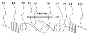
図1に、本発明における光情報記録再生装置の第1の実施の形態における光学系を示す。図には主要な光学ブロックのみを載せている。
図1の符号として、1−1は、レーザー光源であり、後述の実施例においては波長405nmの半導体レーザー装置を使用した。ついで、レーザー光源1−1から出射された光線1−2は、ビーム分割手段の一態様である偏光ビームスプリッター1−3aにより、S偏光とP偏光に分離され、それぞれ光線1−2a及び光線1−2bとして2つの方向に分かれて進む。ここでは、光線1−2aをサーボ用光線、光線1−2bを記録/再生用光線として使用する。なお、1−10は、強度調整手段の一態様である1/2波長板であり、サーボ用光線1−2aと記録/再生用光線1−2bの強度比を調整する。
FIG. 1 shows an optical system in a first embodiment of an optical information recording / reproducing apparatus according to the present invention. Only the main optical blocks are shown in the figure.
As a code | symbol of FIG. 1, 1-1 is a laser light source and used the semiconductor laser apparatus of wavelength 405nm in the below-mentioned Example. Next, the light beam 1-2 emitted from the laser light source 1-1 is separated into S-polarized light and P-polarized light by the polarization beam splitter 1-3a which is an embodiment of the beam splitting unit. -B is divided into two directions. Here, the light beam 1-2a is used as a servo light beam, and the light beam 1-2b is used as a recording / reproducing light beam. Reference numeral 1-10 denotes a half-wave plate which is an embodiment of the intensity adjusting means, and adjusts the intensity ratio between the servo light beam 1-2a and the recording / reproducing light beam 1-2b.
(サーボ側光学系)
サーボ用光線1−2aは、全反射ミラー1−4aで反射され、後に説明するサーボ分波光学系である分波光学系1−5aを通過し、ビーム同軸配置手段の一態様である偏光ビームスプリッター1−3bと対物レンズ1−7を通過した後、記録媒体1−8のサーボ情報面に集光される。ついでサーボ情報面から反射された光は偏光ビームスプリッター1−3bで反射された後、再び分波光学系1−5aに入射する。この光線は、この光学系内において、元の光線軸上から外れて出射され、サーボ検出器であるサーボ用ディテクター1−9aで受光される。
(Servo side optical system)
The servo light beam 1-2a is reflected by the total reflection mirror 1-4a, passes through a demultiplexing optical system 1-5a that is a servo demultiplexing optical system, which will be described later, and is a polarized beam that is one mode of the beam coaxial arrangement means. After passing through the splitter 1-3b and the objective lens 1-7, it is condensed on the servo information surface of the recording medium 1-8. Next, the light reflected from the servo information surface is reflected by the polarization beam splitter 1-3b and then enters the demultiplexing optical system 1-5a again. In this optical system, this light beam is emitted out of the original beam axis and received by a servo detector 1-9a which is a servo detector.
(記録/再生側光学系)
一方、記録/再生用光線1−2bは、全反射ミラー1−4bで反射され、再生用分波光学系である分波光学系1−5bを通過した後、焦点深さ切替手段である焦点深さ切り替え光学系1−6を通過する。その後偏光ビームスプリッター1−3bと対物レンズ1−7を通過した後、記録媒体内のサーボ情報面とは異なる、深さ方向の所定の位置に集光される。ここまでは、記録再生ともに同じである。
記録時においては、この集光された領域の記録材料に微小な屈折率変化が生じ、記録マークが生成される。
(Recording / playback optical system)
On the other hand, the recording / reproducing light beam 1-2b is reflected by the total reflection mirror 1-4b, passes through the demultiplexing optical system 1-5b which is a reproducing demultiplexing optical system, and then is a focal point which is a focal depth switching unit. It passes through the depth switching optical system 1-6. Then, after passing through the polarizing beam splitter 1-3b and the objective lens 1-7, the light is condensed at a predetermined position in the depth direction different from the servo information surface in the recording medium. Up to this point, the recording and reproduction are the same.
At the time of recording, a minute refractive index change occurs in the recording material in the condensed region, and a recording mark is generated.
また再生時においては、記録材料内の記録マーク(微小な屈折率変化領域)からの反射光が、対物レンズ1−7、偏光ビームスプリッター1−3b及び焦点深さ切替光学系1−6を通過した後、分波光学系1−5bに入射する。この反射光は、この分波光学系1−5b内において、元の光軸上から外れて出射され、再生検出器である信号用ディテクター1−9bで受光される。 At the time of reproduction, reflected light from a recording mark (a minute refractive index change region) in the recording material passes through the objective lens 1-7, the polarization beam splitter 1-3b, and the focal depth switching optical system 1-6. Then, the light enters the demultiplexing optical system 1-5b. In the demultiplexing optical system 1-5b, the reflected light is emitted out of the original optical axis and received by the signal detector 1-9b which is a reproduction detector.
なお、前記サーボ用光線1−2aと記録/再生用光線1−2bは、同じ対物レンズ1−7の制御で位置決めされるため、偏光ビームスプリッター1−3cを経た後は、該2つの光線の光軸は同軸上に配置する。 The servo light beam 1-2a and the recording / reproducing light beam 1-2b are positioned under the control of the same objective lens 1-7. Therefore, after passing through the polarization beam splitter 1-3c, the two light beams The optical axis is arranged on the same axis.
ここで、分波光学系1−5a,1−5bについて説明する。ここでいう分波光学系とは、記録媒体に入射する方向に進む光線は分波光学系の前後で偏光状態を変えずに通過し、記録媒体から反射された光線を入射光線の光軸からずらすものである。 Here, the demultiplexing optical systems 1-5a and 1-5b will be described. The demultiplexing optical system here means that a light beam traveling in the direction of incidence on the recording medium passes through the demultiplexing optical system without changing the polarization state, and the light beam reflected from the recording medium is separated from the optical axis of the incident light beam. It is something to shift.
図2は、記録媒体に入射する方向に進む光線に対する分波光学系の作用についての説明図である。分波光学系は、偏光子2−2、ファラデー回転子2−3、偏光ビームスプリッター2−5、ファラデー回転子2−7、偏光子2−9がこの順番で配置されてなるものである。 FIG. 2 is an explanatory diagram of the action of the demultiplexing optical system for light rays traveling in the direction of incidence on the recording medium. The demultiplexing optical system includes a polarizer 2-2, a Faraday rotator 2-3, a polarization beam splitter 2-5, a Faraday rotator 2-7, and a polarizer 2-9 arranged in this order.
分波光学系に入射する光線2−1は、偏光子2−2を通過後、偏光面を45度回転するファラデー回転子2−3を通過する。ついで通過した光は、この偏光面の方向が100%透過するように配置された偏光ビームスプリッター2−5を透過した後、ファラデー回転子2−3とは逆の方向に偏光面を45度回転するファラデー回転子2−7を通過し、偏光子2−2と同じ向きの偏光子2−9を通過する。このようにして透過した光線2−10は、入射光2−1とエネルギーロスがほとんどなく、同じ偏光状態を保つ。 The light beam 2-1 incident on the demultiplexing optical system passes through the polarizer 2-2, and then passes through the Faraday rotator 2-3 that rotates the polarization plane by 45 degrees. Next, the light that has passed through the polarizing beam splitter 2-5 arranged so that the direction of the polarization plane is 100% transmitted, and then the polarization plane is rotated 45 degrees in the direction opposite to that of the Faraday rotator 2-3. Passes through the Faraday rotator 2-7 and passes through the polarizer 2-9 in the same direction as the polarizer 2-2. The light beam 2-10 transmitted in this manner has almost no energy loss as the incident light 2-1, and maintains the same polarization state.
一方、図3は、記録媒体から反射された光線に対する分波光学系の作用についての説明図である。
記録媒体から反射された光線3−1は、偏光子2−9を経て、偏光面を45度回転するファラデー回転子2−7を透過する。透過後の光線3−5の偏光面は前記光線2−4,2−6の偏光面と直交しているため、偏光ビームスプリッター2−5により反射される。その反射光3−7は、入射光3−1とエネルギーロスがほとんどない。
On the other hand, FIG. 3 is an explanatory view of the action of the demultiplexing optical system for the light beam reflected from the recording medium.
The light beam 3-1 reflected from the recording medium passes through the polarizer 2-9 and the Faraday rotator 2-7 that rotates the polarization plane by 45 degrees. Since the polarization plane of the transmitted light beam 3-5 is orthogonal to the polarization planes of the light beams 2-4 and 2-6, it is reflected by the polarization beam splitter 2-5. The reflected light 3-7 has almost no energy loss with the incident light 3-1.
ところで、このような分波光学系を使用する場合、一つの問題点は、図1において光学系を1つの平面内に組めないことである。つまり図3で示す偏光ビームスプリッターから出射される反射光3−7は、図1においてその他の光線で決まる平面上にはなく、45度方向に外れてしまう。 Incidentally, when such a demultiplexing optical system is used, one problem is that the optical system cannot be assembled in one plane in FIG. That is, the reflected light 3-7 emitted from the polarization beam splitter shown in FIG. 3 is not on the plane determined by the other light rays in FIG.
これを解決する方法の一つとして、図3における偏光ビームスプリッターに、図1に示すディテクターを組み込んで一体にする方法が考えられる。
また別の解決方法は、分波光学系を使用せずに、図4に示すような光学系にすることである。この光学系と図1の光学系との構成の違いは、分波光学系1−5a,1−5bを使用しないこと、及び全反射ミラー1−4a,1−4aをハーフミラー1−4c,1−4dに変え、それぞれの後にサーボ用ディテクター1−9cと再生信号用ディテクター1−9dを配置したことである。
As one method for solving this, a method of incorporating the detector shown in FIG. 1 into the polarization beam splitter shown in FIG. 3 can be considered.
Another solution is to use an optical system as shown in FIG. 4 without using a demultiplexing optical system. The difference in configuration between this optical system and the optical system in FIG. 1 is that the demultiplexing optical systems 1-5a and 1-5b are not used, and the total reflection mirrors 1-4a and 1-4a are replaced with half mirrors 1-4c, In other words, the servo detector 1-9c and the reproduction signal detector 1-9d are arranged after each.
この構成では、全ての光学系を同一平面上に組めるというメリットがある。一方で、短所としては、ハーフミラーを使用する関係上、光エネルギーのロスが生じてしまうことである。そのため、記録媒体の光エネルギーに対する記録感度が悪い場合は、記録できない可能性があり、またデータ再生時に記録媒体からの戻り光量が少ない場合は、十分なSN比が得られない可能性がある。そのような場合は、この光学系は適さない。 This configuration has an advantage that all optical systems can be assembled on the same plane. On the other hand, the disadvantage is that light energy is lost due to the use of a half mirror. Therefore, if the recording sensitivity of the recording medium with respect to the light energy is poor, recording may not be possible, and if the amount of light returned from the recording medium is small during data reproduction, a sufficient SN ratio may not be obtained. In such a case, this optical system is not suitable.
つぎに、本実施の形態で用いる記録媒体について説明する。
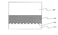
図5に、その記録媒体の構成を示す。
記録媒体は、基板4−1、サーボ情報面4−2、情報記録層4−3、光透過層4−4からなる。
Next, the recording medium used in the present embodiment will be described.
FIG. 5 shows the configuration of the recording medium.
The recording medium includes a substrate 4-1, a servo information surface 4-2, an information recording layer 4-3, and a light transmission layer 4-4.
基板4−1は、ガラスもしくはポリカーボネートなどのプラスチックからなる基板である。また該基板4−1上には、アドレス情報やサーボを取るためのエンボスピット、もしくは案内溝が形成されており、さらにその上に、反射膜としてアルミや銀などの金属膜をスパッターなどの方法により設けて、サーボ情報面4−2としている。 The substrate 4-1 is a substrate made of plastic such as glass or polycarbonate. Further, emboss pits or guide grooves for taking address information and servo are formed on the substrate 4-1, and a metal film such as aluminum or silver is further sputtered thereon as a reflection film. The servo information surface 4-2 is provided.
また、サーボ情報面4−2の上に、情報記録層4−3を有する。情報記録層4−3は、例えばアクリル酸エステルモノマー(p-クミルフェノールエチレンオキシド付加アクリル酸エステル)とウレタン2官能アクリレートオリゴマーを40:60(重量比)、全体に対する0.8wt%の有機金属化合物であり光重合開始剤でもある(ビス(η-2,4-シクロペンタジエン-1-イル)-ビス(2,6-ジフルオロ-3-(1H-ピロール-1-イル)-フェニル)チタニウム(チバ・スペシャリティ・ケミカルズIrg-784、以後Irg-784)を暗室下、混合脱泡し基板上に展開して所定厚みに形成したものである。なお、情報記録層4−3と前記金属膜が反応を起こす場合は、金属膜上に、情報記録層4−3に対し不活性な、例えば酸化ケイ素や窒化ケイ素などの無機膜を設けるとよい。また、サーボ情報面4−2からの反射光が悪影響を及ぼす場合や、サーボ光線のサーボ情報面上での集光により記録材料の反応してしまう場合などは、金属膜上にUV硬化樹脂等で20μm程度のギャップ層を設ける構成も可能である。 Further, an information recording layer 4-3 is provided on the servo information surface 4-2. The information recording layer 4-3 is composed of, for example, an acrylate monomer (p-cumylphenol ethylene oxide-added acrylate ester) and a urethane bifunctional acrylate oligomer at 40:60 (weight ratio), 0.8 wt% of the organometallic compound. And a photopolymerization initiator (bis (η-2,4-cyclopentadien-1-yl) -bis (2,6-difluoro-3- (1H-pyrrol-1-yl) -phenyl) titanium (Ciba・ Specialty Chemicals Irg-784 (hereinafter Irg-784) was mixed and degassed in a dark room and developed on a substrate to form a predetermined thickness, and the information recording layer 4-3 and the metal film reacted. For example, an inorganic film such as silicon oxide or silicon nitride, which is inactive with respect to the information recording layer 4-3, may be provided on the metal film, and reflected light from the servo information surface 4-2 may be generated. Adverse effects Or, such as when reacts recording material by a condenser on the servo information surface of the servo beam, be provided with a gap layer of about 20μm in UV curable resin or the like is also possible on the metal film.
情報記録層4−3の上には、ガラスもしくはポリカーボネートなどのプラスチックからなる基板である光透過層4−4を有する。ここで、光透過層4−4と前記情報記録層4−3が反応を起こす場合は、光透過層4−4上に、情報記録層4−3に対し不活性な、例えば酸化ケイ素や窒化ケイ素などの無機膜を設けるとよい。また、光透過層4−4は光吸収が小さいことはもちろん、偏光状態を極力変えないように、光学的異方性が小さい材料であることが望ましい。 On the information recording layer 4-3, there is a light transmission layer 4-4 which is a substrate made of plastic such as glass or polycarbonate. Here, when the light transmission layer 4-4 reacts with the information recording layer 4-3, it is inactive with respect to the information recording layer 4-3 on the light transmission layer 4-4, such as silicon oxide or nitride. An inorganic film such as silicon may be provided. In addition, the light transmission layer 4-4 is preferably made of a material having small optical anisotropy so that the light absorption is small and the polarization state is not changed as much as possible.
(光情報記録方法)
本発明の光情報記録方法は、一つの記録用光線を記録媒体内に集光させ、光化学反応及び/又は熱化学反応により記録材料内に局所的な屈折率変化を生じさせ情報を記録する方法である。
図6に、記録及び再生時における記録媒体内でのサーボ用光線及び記録/再生用光線の様子を示す。以下、図1及び図6を参照しながら、光情報記録/再生方法の手順を説明する。
(Optical information recording method)
The optical information recording method of the present invention is a method for recording information by condensing one recording beam in a recording medium and causing a local refractive index change in the recording material by a photochemical reaction and / or a thermochemical reaction. It is.
FIG. 6 shows the state of the servo light beam and the recording / reproducing light beam in the recording medium during recording and reproduction. The procedure of the optical information recording / reproducing method will be described below with reference to FIGS.
(S11) サーボ用光線1−2aは、図1のサーボ側光学系を通ってアドレス情報及び/又はサーボ情報がエンボスピットで記録されている面(サーボ情報面)4-2に集光される。ついでサーボ情報面4−2から反射された光は偏光ビームスプリッター1−3bで反射された後、再び分波光学系1−5aに入射する。この光線は、この光学系内において、元の光線軸上から外れて出射され、サーボ検出器であるサーボ用ディテクター1−9aで受光され、アドレス情報及び/又はサーボ情報が読み取られる。
(S12) 読み取られたアドレス情報及び/又はサーボ情報を基に記録/再生用光線1−2bのフォーカス及び横方向(ディスク水平方向)の位置決め制御を対物レンズ1-7の駆動により行う。
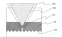
(S13) 記録/再生用光線1−2bは、情報記録層4−3の内部において、サーボ情報面4−2とは深さ方向の異なる所定の位置で集光される。焦点深さの設定に関しては、焦点深さ切り替え光学系1−6の制御により行う。焦点深さの切り替え方法に関しては、いくつかの公知の方法があるが、もっとも単純な方法は2つのレンズの距離を変えることにより合成焦点の距離を変える方法である。また、深さ方向の焦点位置を変える場合、その程度によっては、球面収差補正が必要な場合がある。その場合、信号/再生用光線1−2bの光路中に適宜収差を補正する機構を追加する。なお、偏光ビームスプリッター1−3aによりサーボ用光線1−2aと記録/再生用光線1−2bが互いに直交偏光の関係になるため、情報記録層4−3内でオーバーラップしているにも関わらず、2つの光は干渉しない。そのため、不要な干渉縞の影響は除去できる。
(S14) 記録/再生用光線1−2bの焦点近傍において、情報記録層4−3の記録材料の光吸収と相まって高温となり、マイクロバブル4−5が形成される。マイクロバブル4−5は、記録材料の中に形成される微小な空洞空間である。そのため、マイクロバブル4−5内部は屈折率が1に近い状態にあると考えられ、その周りの記録材料(屈折率、例えば1.5〜1.6)と屈折率差を生じている。これが部分的な屈折率変化となり、情報記録層4−3中に固定される。このマイクロバブル4−5の有無により、情報が記録されるわけである。なお、情報記録層4−3においては、深さ方向の同じ位置の水平方向に所定のパターンでマイクロバブル4−5が形成されて記録面が形成される。
(S11) The servo light beam 1-2a passes through the servo-side optical system of FIG. 1 and is focused on the surface (servo information surface) 4-2 on which address information and / or servo information is recorded by embossed pits. . Next, the light reflected from the servo information surface 4-2 is reflected by the polarization beam splitter 1-3b and then enters the demultiplexing optical system 1-5a again. In this optical system, this light beam is emitted off the original beam axis, received by the servo detector 1-9a which is a servo detector, and the address information and / or servo information is read.
(S12) Based on the read address information and / or servo information, focus of the recording / reproducing light beam 1-2b and positioning control in the horizontal direction (disk horizontal direction) are performed by driving the objective lens 1-7.
(S13) The recording / reproducing light beam 1-2b is condensed at a predetermined position different from the servo information surface 4-2 in the depth direction inside the information recording layer 4-3. The focus depth is set by controlling the focus depth switching optical system 1-6. There are several known methods for switching the depth of focus, but the simplest method is to change the distance of the composite focus by changing the distance between the two lenses. Further, when changing the focal position in the depth direction, spherical aberration correction may be necessary depending on the degree. In that case, a mechanism for appropriately correcting aberration is added in the optical path of the signal / reproducing beam 1-2b. The servo beam 1-2a and the recording / reproducing beam 1-2b are orthogonally polarized with each other by the polarization beam splitter 1-3a, so that the information recording layer 4-3 is overlapped. The two lights do not interfere. Therefore, the influence of unnecessary interference fringes can be removed.
(S14) In the vicinity of the focal point of the recording / reproducing light beam 1-2b, the temperature becomes high due to the light absorption of the recording material of the information recording layer 4-3, and microbubbles 4-5 are formed. The microbubbles 4-5 are minute hollow spaces formed in the recording material. Therefore, it is considered that the inside of the microbubble 4-5 is in a state where the refractive index is close to 1, and a refractive index difference is generated with the surrounding recording material (refractive index, for example, 1.5 to 1.6). This becomes a partial change in refractive index and is fixed in the information recording layer 4-3. Information is recorded depending on the presence or absence of the microbubbles 4-5. In the information recording layer 4-3, microbubbles 4-5 are formed in a predetermined pattern in the horizontal direction at the same position in the depth direction to form a recording surface.
図7は、情報記録層4−3内において、記録面が深さ方向に層状に形成されて記録された状態の模式図である。ここでは、記録/再生用光線1−2bの焦点深さを4種類設定し、4層記録した状態を示す。すなわち、記録面4−3a,4−3b,4−3c,4−3dが深さ方向に所定の間隔dで並んで設けられている。このとき、記録面4−3aとサーボ情報面4−2との間隔d0を前記間隔d以上の間隔とする。これは、各記録面の記録ピットからの反射光量に比べ、サーボ情報面4−2の反射膜からの反射光量は少なくとも一桁以上は大きいため、データ再生時にサーボ情報面からのクロストークの影響を小さくするためである。 FIG. 7 is a schematic view showing a state where the recording surface is formed in a layer shape in the depth direction and recorded in the information recording layer 4-3. Here, four types of focal depths of the recording / reproducing light beam 1-2b are set and four layers are recorded. That is, the recording surfaces 4-3a, 4-3b, 4-3c, and 4-3d are provided side by side at a predetermined interval d in the depth direction. At this time, the interval d0 between the recording surface 4-3a and the servo information surface 4-2 is set to be equal to or greater than the interval d. This is because the amount of reflected light from the reflective film on the servo information surface 4-2 is at least an order of magnitude larger than the amount of reflected light from the recording pits on each recording surface. This is to reduce the size.
(光情報再生方法)
(S21) データ再生においては、サーボ用光線1−2aは、図1のサーボ側光学系を通ってサーボ情報面4-2に集光される。ついでサーボ情報面4−2から反射された光は偏光ビームスプリッター1−3bで反射された後、再び分波光学系1−5aに入射する。この光線は、この光学系内において、元の光線軸上から外れて出射され、サーボ検出器であるサーボ用ディテクター1−9aで受光され、アドレス情報及び/又はサーボ情報が読み取られる。
(S22) 読み取られたアドレス情報及び/又はサーボ情報を基に記録/再生用光線1−2bのフォーカス及び横方向(ディスク水平方向)の位置決め制御を対物レンズ1-7の駆動により行う。
(S23) 記録/再生用光線1−2bは、情報記録層4−3の内部において、光情報記録方法の場合と同様にしてサーボ情報面4−2とは深さ方向の異なる位置で集光される。
(S24) 記録材料内のマイクロバブル4−5を含む記録マーク(微小な屈折率変化領域)からの反射光が、対物レンズ1−7、偏光ビームスプリッター1−3b及び焦点深さ切替光学系1−6を通過した後、分波光学系1−5bに入射する。この反射光は、この分波光学系1−5b内において、元の光軸上から外れて出射され、再生検出器である信号用ディテクター1−9bで受光され、情報が再生される。
(Optical information reproduction method)
(S21) In data reproduction, the servo light beam 1-2a is condensed on the servo information surface 4-2 through the servo-side optical system in FIG. Next, the light reflected from the servo information surface 4-2 is reflected by the polarization beam splitter 1-3b and then enters the demultiplexing optical system 1-5a again. In this optical system, this light beam is emitted off the original beam axis, received by the servo detector 1-9a which is a servo detector, and the address information and / or servo information is read.
(S22) Based on the read address information and / or servo information, focus of the recording / reproducing light beam 1-2b and positioning control in the horizontal direction (disk horizontal direction) are performed by driving the objective lens 1-7.
(S23) The recording / reproducing light beam 1-2b is condensed inside the information recording layer 4-3 at a position different from the servo information surface 4-2 in the depth direction in the same manner as in the optical information recording method. Is done.
(S24) The reflected light from the recording mark (micro refractive index change region) including the microbubbles 4-5 in the recording material is converted into the objective lens 1-7, the polarization beam splitter 1-3b, and the focal depth switching optical system 1. After passing through -6, the light enters the demultiplexing optical system 1-5b. In the demultiplexing optical system 1-5b, the reflected light is emitted out of the original optical axis, received by the signal detector 1-9b, which is a reproduction detector, and information is reproduced.
(第2の実施の形態)
本発明に係る光情報記録方法、光情報再生方法の第2の実施の形態について、本発明に係る光情報記録装置及び光情報再生装置に基づいて説明する。ここでは、光情報記録装置、光情報再生装置それぞれの要件を兼ね備えた光情報記録再生装置として説明するが、該光情報記録再生装置は、本発明の光情報記録方法、光情報再生方法を実現するのに好適な構成となっている。
(Second Embodiment)
A second embodiment of the optical information recording method and the optical information reproducing method according to the present invention will be described based on the optical information recording apparatus and the optical information reproducing apparatus according to the present invention. Here, the optical information recording / reproducing apparatus is described as an optical information recording / reproducing apparatus having both requirements of the optical information recording apparatus and the optical information reproducing apparatus, and the optical information recording / reproducing apparatus realizes the optical information recording method and optical information reproducing method of the present invention. This is a suitable configuration.
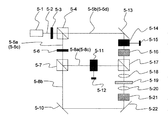
図8に、本発明における光情報記録再生装置の第2の実施の形態における光学系を示す。図には主要な光学ブロックのみを載せている。
図8の符号として、5−1は、レーザー光源であり、後述の実施例2においては波長405nmの半導体レーザー装置を使用した。また、本実施の形態においては、2つの光線を干渉させるため、図示しない外部共振器により、シングルモードにしている。以降、記録時と再生時に分けて説明する。
(1)記録時
レーザー光源5−1から出射された光線5−2は、ビーム分割手段の一態様である偏光ビームスプリッター5−4により、S偏光とP偏光に分離され、それぞれ光線5−5a及び光線5−5bとして2つの方向に分かれて進む。ここでは、光線5−5bを第1の記録用光線として使用する。なお、5−3は、強度調整手段の一態様である1/2波長板であり、光線5−5aと第1の記録用光線5−5bの強度比を調整する。
FIG. 8 shows an optical system in a second embodiment of the optical information recording / reproducing apparatus of the present invention. Only the main optical blocks are shown in the figure.
8, reference numeral 5-1 denotes a laser light source. In Example 2 to be described later, a semiconductor laser device having a wavelength of 405 nm was used. In the present embodiment, in order to cause two light beams to interfere with each other, a single mode is set by an external resonator (not shown). Hereinafter, a description will be given separately for recording and reproduction.
(1) At the time of recording The light beam 5-2 emitted from the laser light source 5-1 is separated into S-polarized light and P-polarized light by the polarization beam splitter 5-4, which is an embodiment of the beam splitting means, and the light beam 5-5a is obtained. And the light beam 5-5b proceeds in two directions. Here, the light beam 5-5b is used as the first recording light beam. Reference numeral 5-3 denotes a half-wave plate which is an embodiment of the intensity adjusting means, and adjusts the intensity ratio between the light beam 5-5a and the first recording light beam 5-5b.
光線5−5aはさらに、偏光ビームスプリッター5−7により、サーボ用光線5−8aと第2の記録用光線5−8bに分離される。なお、5−6は1/2波長板であり、サーボ用光線5−8aと第2の記録用光線5−8bの強度比を調整する。 The light beam 5-5a is further separated into a servo light beam 5-8a and a second recording light beam 5-8b by the polarization beam splitter 5-7. Reference numeral 5-6 denotes a half-wave plate, which adjusts the intensity ratio between the servo light beam 5-8a and the second recording light beam 5-8b.
(サーボ側光学系)
サーボ用光線5−8aは、第1の実施の形態と同様にサーボ側光学系を経由する。すなわち、第1の実施の形態における分波光学系と同じ分波光学系5−11を通過し、偏光ビームスプリッター5−17と対物レンズ5−18を通過した後、記録媒体5−19のサーボ情報面に集光される。
(Servo side optical system)
The servo light beam 5-8a passes through the servo-side optical system as in the first embodiment. That is, after passing through the same demultiplexing optical system 5-11 as the demultiplexing optical system in the first embodiment, after passing through the polarization beam splitter 5-17 and the objective lens 5-18, the servo of the recording medium 5-19 is performed. Focused on the information surface.
サーボ情報面から反射された光は偏光ビームスプリッター5−17で反射された後、再び分波光学系5−11に入射する。この光線は、この分波光学系5−11内において、元の光線軸上から外れて出射され、サーボ用ディテクター5−12で受光される。 The light reflected from the servo information surface is reflected by the polarization beam splitter 5-17 and then enters the demultiplexing optical system 5-11 again. In the demultiplexing optical system 5-11, this light beam is emitted off the original beam axis and received by the servo detector 5-12.
(記録/再生側光学系)
第1の記録用光線5−5bは、全反射ミラー5−13で反射され、分波光学系5−14を通過した後、焦点深さ切り替え光学系5−16を通過する。その後、偏光ビームスプリッター5−17と対物レンズ5−18を通過した後、記録媒体5−19内の、サーボ情報面とは異なる、所定の深さ位置に集光される。
(Recording / playback optical system)
The first recording light beam 5-5b is reflected by the total reflection mirror 5-13, passes through the demultiplexing optical system 5-14, and then passes through the focus depth switching optical system 5-16. Thereafter, after passing through the polarizing beam splitter 5-17 and the objective lens 5-18, the light is condensed at a predetermined depth position in the recording medium 5-19 which is different from the servo information surface.
第2の記録用光線5−8bは、全反射ミラー5−10,5−22で反射され、焦点深さ切り替え光学系5−21を通過する。その後、対物レンズ5−20により、記録媒体5−19内の、第1の記録用光線5−5bと同じ深さ位置に集光される。 The second recording light beam 5-8b is reflected by the total reflection mirrors 5-10 and 5-22 and passes through the focal depth switching optical system 5-21. Thereafter, the light is condensed at the same depth position as the first recording light beam 5-5b in the recording medium 5-19 by the objective lens 5-20.
この2つ光(第1の記録用光線5−5b,第2の記録用光線5−8b)が集光された領域に微小な干渉縞が形成され、記録材料内に微小な屈折率変調が生じ、記録マークが生成される。 A minute interference fringe is formed in a region where the two lights (first recording light beam 5-5b and second recording light beam 5-8b) are condensed, and minute refractive index modulation is caused in the recording material. Occurs and a recording mark is generated.
(2)再生時
レーザー光源5−1から出射された光線5−2は、偏光ビームスプリッター5−4により、S偏光とP偏光に分離され、それぞれ光線5−5c及び光線5−5dとして2つの方向に分かれて進む。ここでは、光線5−5dを再生用光線として使用する。なお、5−3は、強度調整手段の一態様である1/2波長板であり、光線5−5cと再生用光線5−5dの強度比を調整する。
(2) During reproduction The light beam 5-2 emitted from the laser light source 5-1 is separated into S-polarized light and P-polarized light by the polarization beam splitter 5-4, and two light beams 5-5c and 5-5d are obtained. Proceed divided into directions. Here, the light beam 5-5d is used as a reproduction light beam. Reference numeral 5-3 denotes a half-wave plate which is an embodiment of the intensity adjusting means, and adjusts the intensity ratio of the light beam 5-5c and the reproduction light beam 5-5d.
光線5−5cは、1/2波長板5−6により、偏光ビームスプリッター5−7において反射される成分のみ(P偏光、S偏光いずれか)となるように調整され、偏光ビームスプリッター5−7において反射され、サーボ用光線5−8cとなる。 The light beam 5-5c is adjusted by the half-wave plate 5-6 so as to be only the component reflected by the polarization beam splitter 5-7 (either P-polarized light or S-polarized light), and the polarized beam splitter 5-7. Is reflected to become a servo beam 5-8c.
(サーボ側光学系)
サーボ用光線5−8cは、分波光学系5−11を通過し、偏光ビームスプリッター5−17と対物レンズ5−18を通過した後、記録媒体5−19のサーボ情報面に集光される。
(Servo side optical system)
The servo light beam 5-8c passes through the demultiplexing optical system 5-11, passes through the polarization beam splitter 5-17 and the objective lens 5-18, and is then condensed on the servo information surface of the recording medium 5-19. .
サーボ情報面から反射された光は偏光ビームスプリッター5−17で反射された後、再び分波光学系5−11に入射する。この光線は、この分波光学系5−11内において、元の光線軸上から外れて出射され、サーボ用ディテクター5−12で受光される。 The light reflected from the servo information surface is reflected by the polarization beam splitter 5-17 and then enters the demultiplexing optical system 5-11 again. In the demultiplexing optical system 5-11, this light beam is emitted off the original beam axis and received by the servo detector 5-12.
(記録/再生側光学系)
再生用光線5−5dは、全反射ミラー5−13で反射され、分波光学系5−14を通過した後、焦点深さ切り替え光学系5−16を通過する。その後、偏光ビームスプリッター5−17と対物レンズ5−18を通過した後、記録媒体5−19内の、サーボ情報面とは異なる、所定の深さ位置に集光される。
(Recording / playback optical system)
The reproduction light beam 5-5d is reflected by the total reflection mirror 5-13, passes through the demultiplexing optical system 5-14, and then passes through the focus depth switching optical system 5-16. Thereafter, after passing through the polarizing beam splitter 5-17 and the objective lens 5-18, the light is condensed at a predetermined depth position in the recording medium 5-19 which is different from the servo information surface.
ついで再生用光線5−5dの、記録マーク(微小な屈折率変調領域)からの回折光(反射光)が、対物レンズ5−18、偏光ビームスプリッター5−17及び焦点深さ切り替え光学系5−16を通過後、分波光学系5−14に入射する。この反射光は、この分波光学系5−14内において元の光軸上から外れて出射され、再生検出器である信号用ディテクター5−15で受光される。 Next, the diffracted light (reflected light) from the recording mark (a minute refractive index modulation region) of the reproducing light beam 5-5d is converted into the objective lens 5-18, the polarization beam splitter 5-17, and the focal depth switching optical system 5-. After passing through 16, the light enters the demultiplexing optical system 5-14. The reflected light is emitted out of the original optical axis in the demultiplexing optical system 5-14, and is received by the signal detector 5-15 which is a reproduction detector.
なお、サーボ用光線5−8aと2つの記録用光線(第1の記録用光線5−5b、第2の記録用光線5−8b)、サーボ用光線5−8cと再生用光線5−5dは、同軸上に配置するのが好ましい。 The servo beam 5-8a, two recording beams (first recording beam 5-5b, second recording beam 5-8b), servo beam 5-8c, and reproduction beam 5-5d are as follows. It is preferable to arrange them on the same axis.
つぎに、本実施の形態で用いる記録媒体について説明する。
図9に、その記録媒体の構成を示す。
記録媒体は、基板6−1、サーボ情報面6−2、ホログラム記録層6−3、光透過層6−4からなる。
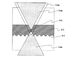
Next, the recording medium used in the present embodiment will be described.
FIG. 9 shows the configuration of the recording medium.
The recording medium includes a substrate 6-1, a servo information surface 6-2, a hologram recording layer 6-3, and a light transmission layer 6-4.
基板6−1は、ガラスもしくはポリカーボネートなどのプラスチックからなる基板である。また該基板6−1上には、アドレス情報やサーボを取るためのエンボスピット、もしくは案内溝が形成されており、さらにその上に、半反射膜としてアルミや銀などの金属膜をスパッターなどの方法により設けて、サーボ情報面6−2としている。この半反射膜は照射される光に対し、一定の割合で反射し、一定の割合で透過する。これにより、サーボ用光線はサーボ情報面6−2で反射され、第2の記録用光線5−8bはサーボ情報面6−2で透過する。 The substrate 6-1 is a substrate made of plastic such as glass or polycarbonate. Emboss pits or guide grooves for taking address information and servo are formed on the substrate 6-1, and a metal film such as aluminum or silver is further sputtered thereon as a semi-reflective film. The servo information surface 6-2 is provided by a method. This semi-reflective film reflects at a certain rate with respect to the irradiated light and transmits at a certain rate. Thus, the servo light beam is reflected by the servo information surface 6-2, and the second recording light beam 5-8b is transmitted by the servo information surface 6-2.
また、サーボ情報面6−2の上に、ホログラム記録層6−3を有する。なお、ホログラム記録層6−3と前記半反射膜(金属膜)が反応を起こす場合は、半反射膜上に、ホログラム記録層6−3に対し不活性な、例えば酸化ケイ素や窒化ケイ素などの無機膜を設けるとよい。また、サーボ情報面6−2からの反射光が悪影響を及ぼす場合や、サーボ用光線のサーボ情報面上での集光により記録材料の反応してしまう場合などは、半反射膜上にUV硬化樹脂等で20μm程度のギャップ層を設ける構成も可能である。 Further, a hologram recording layer 6-3 is provided on the servo information surface 6-2. When the hologram recording layer 6-3 reacts with the semi-reflective film (metal film), the semi-reflective film is inert to the hologram recording layer 6-3, such as silicon oxide or silicon nitride. An inorganic film may be provided. In addition, when the reflected light from the servo information surface 6-2 has an adverse effect, or when the recording material reacts due to condensing of the servo light beam on the servo information surface, UV curing is performed on the semi-reflective film. A structure in which a gap layer of about 20 μm is provided with resin or the like is also possible.
情報記録層6−3の上には、ガラスもしくはポリカーボネートなどのプラスチックからなる基板である光透過層6−4を有する。ここで、光透過層6−4と前記ホログラム記録層6−3が反応を起こす場合は、光透過層6−4上に、ホログラム記録層6−3に対し不活性な、例えば酸化ケイ素や窒化ケイ素などの無機膜を設けるとよい。また、光透過層6−4は光吸収が小さいことはもちろん、偏光状態を極力変えないように、光学的異方性が小さい材料であることが望ましい。 On the information recording layer 6-3, there is a light transmission layer 6-4 which is a substrate made of plastic such as glass or polycarbonate. Here, when the light transmission layer 6-4 reacts with the hologram recording layer 6-3, it is inactive with respect to the hologram recording layer 6-3 on the light transmission layer 6-4, such as silicon oxide or nitride. An inorganic film such as silicon may be provided. The light transmitting layer 6-4 is preferably made of a material having a small optical anisotropy so as not to change the polarization state as much as possible as well as having a small light absorption.
(光情報記録方法)
本発明の光情報記録方法は、対向する2つの記録用光線を記録媒体の同一の深さ位置に集光させ、その干渉縞を記録媒体内に微小なホログラムとして情報を記録する方法である。
図10に、記録時における記録媒体内でのサーボ用光線及び記録用光線の様子を示す。以下、図8及び図10を参照しながら、光情報記録方法の手順を説明する。
(Optical information recording method)
The optical information recording method of the present invention is a method of condensing two opposing recording light beams at the same depth position of a recording medium, and recording the information as a minute hologram in the recording medium.
FIG. 10 shows the state of the servo light beam and the recording light beam in the recording medium during recording. Hereinafter, the procedure of the optical information recording method will be described with reference to FIGS.
(S31) サーボ用光線5−8aは、図8のサーボ側光学系を通ってアドレス情報及び/又はサーボ情報がエンボスピットで記録されている面(サーボ情報面)6-2に集光される。ついでサーボ情報面6−2から反射された光は偏光ビームスプリッター5−17で反射された後、再び分波光学系5−11に入射する。この光線は、この分波光学系5−11内において、元の光線軸上から外れて出射され、サーボ用ディテクター5−12で受光され、アドレス情報及び/又はサーボ情報が読み取られる。
(S32) 読み取られたアドレス情報及び/又はサーボ情報を基に第1の記録用光線5−5b、第2の記録用光線5−8bのフォーカス及び横方向(ディスク水平方向)の位置決め制御を対物レンズ5−18,5−20の駆動により行う。
(S33) 第1の記録用光線5−5b及び第2の記録用光線5−8bは、ホログラム記録層6−3の内部において、サーボ情報面6−2とは深さ方向の異なる所定の同じ位置で集光される。焦点深さの設定に関しては、焦点深さ切り替え光学系5−16,5−21の制御により行う。また、深さ方向の焦点位置を変える場合、その程度によっては、球面収差補正が必要な場合がある。その場合、第1の記録用光線5−5b及び第2の記録用光線5−8bの光路中に適宜収差を補正する機構を追加する。なお、偏光ビームスプリッター5−4,5−7によりサーボ用光線5−8aと記録用光線(第1の記録用光線5−5b及び第2の記録用光線5−8b)とが互いに直交偏光の関係になるため、ホログラム記録層6−3内でオーバーラップしているにも関わらず、サーボ用光線5−8aと記録用光線は干渉しない。そのため、不要な干渉縞の影響は除去できる。
(S34) 第1の記録用光線5−5b及び第2の記録用光線5−8bの焦点近傍において、両者の光が干渉し、その干渉縞がホログラム記録層6−3において屈折率分布6−5として記録される。この屈折率分布6−5の有無により、情報が記録されるわけである。なお、ホログラム記録層6−3においては、深さ方向の同じ位置の水平方向に所定のパターンで屈折率分布6−5が形成されて記録面が形成される。そして、第1の記録用光線5−5b及び第2の記録用光線5−8bの焦点深さが適宜複数種類に設定されることにより、記録面が深さ方向に層状に形成されて記録される。
(S31) The servo light beam 5-8a is focused on the surface (servo information surface) 6-2 on which address information and / or servo information is recorded in the embossed pits through the servo side optical system of FIG. . Next, the light reflected from the servo information surface 6-2 is reflected by the polarization beam splitter 5-17, and then enters the demultiplexing optical system 5-11 again. In the demultiplexing optical system 5-11, this light beam is emitted out of the original beam axis, received by the servo detector 5-12, and the address information and / or servo information is read.
(S32) Based on the read address information and / or servo information, the focus and lateral (disk horizontal direction) positioning control of the first recording light beam 5-5b and the second recording light beam 5-8b are objective. This is done by driving the lenses 5-18 and 5-20.
(S33) The first recording light beam 5-5b and the second recording light beam 5-8b are the same in the hologram recording layer 6-3 and different in the depth direction from the servo information surface 6-2. Focused at the position. The focus depth is set by controlling the focus depth switching optical systems 5-16 and 5-21. Further, when changing the focal position in the depth direction, spherical aberration correction may be necessary depending on the degree. In that case, a mechanism for appropriately correcting aberration is added in the optical path of the first recording light beam 5-5b and the second recording light beam 5-8b. The polarization beam splitters 5-4 and 5-7 cause the servo light beam 5-8a and the recording light beam (the first recording light beam 5-5b and the second recording light beam 5-8b) to be orthogonally polarized with each other. Therefore, the servo light beam 5-8a and the recording light beam do not interfere with each other even though they overlap in the hologram recording layer 6-3. Therefore, the influence of unnecessary interference fringes can be removed.
(S34) In the vicinity of the focal points of the first recording light beam 5-5b and the second recording light beam 5-8b, both lights interfere with each other, and the interference fringes in the hologram recording layer 6-3 have a refractive index distribution 6-. Recorded as 5. Information is recorded depending on the presence or absence of the refractive index distribution 6-5. In the hologram recording layer 6-3, a refractive index distribution 6-5 is formed in a predetermined pattern in the horizontal direction at the same position in the depth direction to form a recording surface. Then, when the focal depths of the first recording light beam 5-5b and the second recording light beam 5-8b are appropriately set to a plurality of types, the recording surface is formed in a layer shape in the depth direction and recorded. The
(光情報再生方法)
図11に、再生時における記録媒体内でのサーボ用光線及び記録用光線の様子を示す。以下、図8及び図11を参照しながら、光情報再生方法の手順を説明する。
(S41) データ再生においては、サーボ用光線5−8cは、図8のサーボ側光学系を通ってサーボ情報面6-2に集光される。ついでサーボ情報面6−2から反射された光は偏光ビームスプリッター5−17で反射された後、再び分波光学系5−11に入射する。この光線は、この分波光学系5−11内において、元の光線軸上から外れて出射され、サーボ用ディテクター5−12で受光され、アドレス情報及び/又はサーボ情報が読み取られる。
(S42) 読み取られたアドレス情報及び/又はサーボ情報を基に再生用光線5−5dのフォーカス及び横方向(ディスク水平方向)の位置決め制御を対物レンズ5−18の駆動により行う。
(S43) 再生用光線5−5dは、ホログラム記録層6−3の内部において、光情報記録方法の場合と同様にしてサーボ情報面6−2とは深さ方向の異なる位置で集光される。
(S44) 記録材料内の屈折率分布6−5を含む記録マーク(干渉縞)からの反射光(回折光)が、対物レンズ5−18、偏光ビームスプリッター5−17及び焦点深さ切り替え光学系5−16を通過後、分波光学系5−14に入射する。この反射光は、この分波光学系5−14内において元の光軸上から外れて出射され、再生検出器である信号用ディテクター5−15で受光され、情報が再生される。
(Optical information reproduction method)
FIG. 11 shows the state of the servo light beam and the recording light beam in the recording medium during reproduction. Hereinafter, the procedure of the optical information reproducing method will be described with reference to FIGS.
(S41) In data reproduction, the servo light beam 5-8c is condensed on the servo information surface 6-2 through the servo side optical system of FIG. Next, the light reflected from the servo information surface 6-2 is reflected by the polarization beam splitter 5-17, and then enters the demultiplexing optical system 5-11 again. In the demultiplexing optical system 5-11, this light beam is emitted out of the original beam axis, received by the servo detector 5-12, and the address information and / or servo information is read.
(S42) Based on the read address information and / or servo information, focus of the reproduction light beam 5-5d and positioning control in the horizontal direction (disk horizontal direction) are performed by driving the objective lens 5-18.
(S43) The reproducing light beam 5-5d is condensed at a position different from the servo information surface 6-2 in the depth direction in the hologram recording layer 6-3 in the same manner as in the optical information recording method. .
(S44) The reflected light (diffracted light) from the recording mark (interference fringe) including the refractive index distribution 6-5 in the recording material is converted into the objective lens 5-18, the polarization beam splitter 5-17, and the focal depth switching optical system. After passing through 5-16, the light enters the demultiplexing optical system 5-14. The reflected light is emitted out of the original optical axis in the demultiplexing optical system 5-14, received by the signal detector 5-15 as a reproduction detector, and information is reproduced.
以下、本発明の実施例について説明する。
(実施例1)
図1に示した本発明の光情報記録再生装置を用いて第1の実施の形態に示した本発明の光情報記録方法により図5の記録媒体に情報を記録した。
このときの条件は次のとおりである。
(1)光情報記録再生装置(図1)
・レーザー光源1−1:波長405nmの半導体レーザー
・対物レンズ1−7:開口数0.6
(2)記録媒体(図5)
・情報記録層4−3:
アクリル酸エステルモノマー(p-クミルフェノールエチレンオキシド付加アクリル酸エステル)とウレタン2官能アクリレートオリゴマーを40:60(重量比)、全体に対する0.8wt%の有機金属化合物であり光重合開始剤でもある(ビス(η-2,4-シクロペンタジエン-1-イル)-ビス(2,6-ジフルオロ-3-(1H-ピロール-1-イル)-フェニル)チタニウム(チバ・スペシャリティ・ケミカルズIrg-784)を暗室下、混合脱泡し基板4−1上に展開して0.25μmの厚みに形成した。
・光透過層4−4:厚み0.35μm
・図5の構成に作製したものを、高圧水銀灯(波長365nmおけるパワー密度30mW/cm2)を60分照射して光硬化させ(初期化)、記録媒体とした。
(3)光情報記録条件
以下の手順、条件で光情報記録を行った。
(S51) サーボ用光線1−2aを、図1のサーボ側光学系を通してサーボ情報面4-2に集光させた。このときの入射パワーを記録媒体への照射光線のうち、最も小さくして1mWとした。ついでその反射光からサーボ用ディテクター1−9aでアドレス情報及び/又はサーボ情報を読み取った。
(S52) 読み取ったアドレス情報及び/又はサーボ情報を基に記録/再生用光線1−2bのフォーカス及び横方向(ディスク水平方向)の位置決め制御を対物レンズ1-7の駆動により行う。
(S53) 記録/再生用光線1−2bを、情報記録層4−3の内部において、サーボ情報面4−2とは深さ方向の異なる所定の位置で集光した。このときの入射パワーを50mWとした。
(S54) 記録/再生用光線1−2bの焦点近傍において、マイクロバブル4−5が形成された。本実施例では、マイクロバブル4−5の横方向の広がりが0.7μm、縦の広がりが2μmであった。また、同様の記録を深さ位置を4段階に変化させて、図7のように4つの記録面を深さ方向に層状に形成した。このときの記録面同士の間隔dを40μm、記録面4−3aとサーボ情報面4−2との間隔d0を70μmとした。
以上の条件により、確実な光線の位置決め制御を行って安定した記録を行うことができた。また記録を行った後、同じ光情報記録再生装置によって記録された情報の再生を行ったところ、サーボ情報面4−2からのクロストークの影響もなく、良好に再生を行うことができた。
Examples of the present invention will be described below.
Example 1
Information was recorded on the recording medium of FIG. 5 by the optical information recording method of the present invention shown in the first embodiment using the optical information recording / reproducing apparatus of the present invention shown in FIG.
The conditions at this time are as follows.
(1) Optical information recording / reproducing apparatus (FIG. 1)
Laser light source 1-1: Semiconductor laser having a wavelength of 405 nm Objective lens 1-7: Numerical aperture 0.6
(2) Recording medium (Fig. 5)
Information recording layer 4-3:
Acrylic acid ester monomer (p-cumylphenol ethylene oxide-added acrylic acid ester) and urethane bifunctional acrylate oligomer are 40:60 (weight ratio), 0.8 wt% of organometallic compound and photopolymerization initiator. Bis (η-2,4-cyclopentadien-1-yl) -bis (2,6-difluoro-3- (1H-pyrrol-1-yl) -phenyl) titanium (Ciba Specialty Chemicals Irg-784) In the dark room, the mixture was degassed and developed on the substrate 4-1, so as to have a thickness of 0.25 μm.
Light transmitting layer 4-4: thickness 0.35 μm
The product produced in the configuration of FIG. 5 was irradiated with a high-pressure mercury lamp (power density 30 mW / cm 2 at a wavelength of 365 nm) for 60 minutes to be photocured (initialization) to obtain a recording medium.
(3) Optical information recording conditions Optical information recording was performed according to the following procedures and conditions.
(S51) The servo light beam 1-2a was condensed on the servo information surface 4-2 through the servo side optical system of FIG. The incident power at this time was set to 1 mW, which is the smallest of the light rays applied to the recording medium. Next, address information and / or servo information was read from the reflected light by the servo detector 1-9a.
(S52) Based on the read address information and / or servo information, focus of the recording / reproducing light beam 1-2b and positioning control in the horizontal direction (disk horizontal direction) are performed by driving the objective lens 1-7.
(S53) The recording / reproducing light beam 1-2b was condensed inside the information recording layer 4-3 at a predetermined position different from the servo information surface 4-2 in the depth direction. The incident power at this time was 50 mW.
(S54) Microbubbles 4-5 were formed in the vicinity of the focal point of the recording / reproducing light beam 1-2b. In this example, the microbubble 4-5 had a lateral spread of 0.7 μm and a vertical spread of 2 μm. Further, in the same recording, the depth position was changed in four steps, and four recording surfaces were formed in layers in the depth direction as shown in FIG. At this time, the interval d between the recording surfaces was 40 μm, and the interval d0 between the recording surface 4-3a and the servo information surface 4-2 was 70 μm.
Under the above conditions, reliable light beam positioning control was performed and stable recording could be performed. Further, after the recording, when the information recorded by the same optical information recording / reproducing apparatus was reproduced, the reproduction could be performed satisfactorily without the influence of the crosstalk from the servo information plane 4-2.
(実施例2)
図8に示した本発明の光情報記録再生装置を用いて第2の実施の形態に示した本発明の光情報記録方法により図9の記録媒体に情報を記録した。
このときの条件は次のとおりである。
(1)光情報記録再生装置(図8)
・レーザー光源5−1:波長405nmの半導体レーザー
・対物レンズ5−18,5−20:開口数0.6
(2)記録媒体(図9)
・半反射膜:Ag膜(厚さ5nm)(波長405nmのレーザー光の反射率10%、透過率80%)
・ホログラム記録層6−3は、公知の記録材料で厚さ0.25μmで形成。
・光透過層4−4:厚み0.35μm
(3)光情報記録条件
以下の手順、条件で光情報記録を行った。
(S61) サーボ用光線5−8aを、図8のサーボ側光学系を通してサーボ情報面6-2に集光させた。このときの入射パワーを記録媒体への照射光線のうち、最も小さくして1mWとした。ついでその反射光からサーボ用ディテクター5−12でアドレス情報及び/又はサーボ情報を読み取った。
(S62) 読み取ったアドレス情報及び/又はサーボ情報を基に第1の記録用光線5−5b,第2の記録用光線5−8bのフォーカス及び横方向(ディスク水平方向)の位置決め制御を対物レンズ5−18,5−20の駆動により行った。
(S63) 第1の記録用光線5−5b及び第2の記録用光線5−8bを、ホログラム記録層6−3の内部において、サーボ情報面6−2とは深さ方向の異なる所定の同じ位置で集光した。このときの入射パワーを5mWとした。
(S64) 第1の記録用光線5−5b及び第2の記録用光線5−8bの焦点近傍において、屈折率分布6−5が形成された。また、同様の記録を深さ位置を4段階に変化させて、4つの記録面を深さ方向に層状に形成した。このときの記録面同士の間隔dを40μm、サーボ情報面6−2とサーボ情報面6−2に隣接する記録面との間隔d0を70μmとした。
以上の条件により、確実な光線の位置決め制御を行って安定した記録を行うことができた。また記録を行った後、同じ光情報記録再生装置によって記録された情報の再生を行ったところ、サーボ情報面6−2からの反射光の影響もなく、良好に再生を行うことができた。
(Example 2)
Information was recorded on the recording medium of FIG. 9 by the optical information recording method of the present invention shown in the second embodiment using the optical information recording / reproducing apparatus of the present invention shown in FIG.
The conditions at this time are as follows.
(1) Optical information recording / reproducing apparatus (FIG. 8)
Laser light source 5-1: Semiconductor laser with wavelength of 405 nm Objective lens 5-18, 5-20: Numerical aperture 0.6
(2) Recording medium (Fig. 9)
Semi-reflective film: Ag film (thickness 5 nm) (10% reflectance and 80% transmittance of laser light having a wavelength of 405 nm)
The hologram recording layer 6-3 is formed of a known recording material with a thickness of 0.25 μm.
Light transmitting layer 4-4: thickness 0.35 μm
(3) Optical information recording conditions Optical information recording was performed according to the following procedures and conditions.
(S61) The servo light beam 5-8a was condensed on the servo information surface 6-2 through the servo side optical system of FIG. The incident power at this time was set to 1 mW, which is the smallest of the light rays applied to the recording medium. Next, address information and / or servo information was read from the reflected light by a servo detector 5-12.
(S62) Based on the read address information and / or servo information, focus and lateral (disk horizontal direction) positioning control of the first recording light beam 5-5b and the second recording light beam 5-8b is performed on the objective lens. This was performed by driving 5-18 and 5-20.
(S63) The first recording light beam 5-5b and the second recording light beam 5-8b are arranged in the hologram recording layer 6-3 with a predetermined same difference in the depth direction from the servo information surface 6-2. Focused at the position. The incident power at this time was 5 mW.
(S64) A refractive index distribution 6-5 was formed in the vicinity of the focal point of the first recording light beam 5-5b and the second recording light beam 5-8b. Further, in the same recording, the depth position was changed in four steps, and four recording surfaces were formed in layers in the depth direction. At this time, the interval d between the recording surfaces was 40 μm, and the interval d0 between the servo information surface 6-2 and the recording surface adjacent to the servo information surface 6-2 was 70 μm.
Under the above conditions, reliable light beam positioning control was performed and stable recording could be performed. Further, after the recording, when the information recorded by the same optical information recording / reproducing apparatus was reproduced, it was possible to reproduce the information satisfactorily without the influence of the reflected light from the servo information surface 6-2.
1−1,5−1・・・レーザー光源、1−2,5−2・・・レーザー光線、1−2a,5−5b,5−8a,5−8c・・・サーボ用光線、1−2b・・・記録/再生用光線、1−3a,1−3b,2−5,5−4,5−7,5−17・・・偏光ビームスプリッター、1−4a,1−4b、5−10,5−13,5−22・・・全反射ミラー、1−4c、1−4d・・・ハーフミラー、1−5a,1−5b,5−11,5−14・・・分波光学系、1−6,5−16,5−21・・・焦点深さ切替光学系、1−7,5−18,5−20・・・対物レンズ、1−8,5−19・・・記録媒体、1−9a,1−9b,1−9c,1−9d,5−12,5−15・・・ディテクター、1−10,5−3,5−6・・・1/2波長板、2−1,2−4,2−6,2−8,2−10,3−1,3−3,3−5,3−7,5−5a・・・光線、2−2,2−9・・・偏光子、2−3,2−7・・・ファラデー回転子、4−1,6−1・・・基板、4−2,6−2・・・サーボ情報面、4−3・・・情報記録層、4−3a,4−3b,4−3c,4−3d・・・記録面、4−4,6−4・・・光透過層、4−5・・・マイクロバブル、5−5b・・・第1の記録用光線、5−5d・・・再生用光線、5−8b・・・第2の記録用光線、6−3・・・ホログラム記録層、6−5・・・屈折率分布 1-1, 5-1 ... laser light source, 1-2, 5-2 ... laser beam, 1-2a, 5-5b, 5-8a, 5-8c ... servo beam, 1-2b ... Recording / reproducing beam, 1-3a, 1-3b, 2-5, 5-4, 5-7, 5-17 ... Polarizing beam splitter, 1-4a, 1-4b, 5-10 , 5-13, 5-22... Total reflection mirror, 1-4c, 1-4d... Half mirror, 1-5a, 1-5b, 5-11, 5-14. 1-6, 5-16, 5-21... Depth-of-focus switching optical system, 1-7, 5-18, 5-20... Objective lens, 1-8, 5-19. Medium, 1-9a, 1-9b, 1-9c, 1-9d, 5-12, 5-15... Detector, 1-10, 5-3, 5-6. 2-1, 2-4 2-6, 2-8, 2-10, 3-1, 3-3, 3-5, 3-7, 5-5a ... rays, 2-2, 2-9 ... polarizer, 2 -3, 2-7 ... Faraday rotator, 4-1, 6-1 ... substrate, 4-2, 6-2 ... servo information surface, 4-3 ... information recording layer, 4 -3a, 4-3b, 4-3c, 4-3d... Recording surface, 4-4, 6-4... Light transmission layer, 4-5. 1 recording beam, 5-5d... Reproducing beam, 5-8b... Second recording beam, 6-3... Hologram recording layer, 6-5.
Claims (17)
一つのレーザー光源からのレーザー光線を、アドレス情報及び/又はサーボ情報を読み取るための光線(光線1)、記録媒体内に情報を記録するための光線(光線2)を含む2つ以上のレーザー光線に分割し、ついで前記光線1と光線2の光軸を同軸上に配置した上で、該光線1を前記サーボ情報面に照射して、該光線1の反射光からアドレス情報及び/又はサーボ情報を読み取り、該読み取ったアドレス情報及び/又はサーボ情報に基づいて前記光線2を前記記録媒体の水平方向の所定の位置で深さ方向の任意の位置に焦点を結ぶように照射して記録を行うことを特徴とする光情報記録方法。 An optical information recording method for recording information three-dimensionally by irradiating a laser beam into a recording medium having a servo information surface on which address information and / or servo information is recorded,
A laser beam from one laser light source is divided into two or more laser beams including a beam for reading address information and / or servo information (beam 1) and a beam for recording information in a recording medium (beam 2). Then, after the optical axes of the light beam 1 and the light beam 2 are arranged coaxially, the servo information surface is irradiated with the light beam 1, and address information and / or servo information is read from the reflected light of the light beam 1. , Recording is performed by irradiating the light beam 2 at a predetermined position in the horizontal direction of the recording medium so as to focus on an arbitrary position in the depth direction based on the read address information and / or servo information. An optical information recording method.
1つのレーザー光源と、
該レーザー光源からのレーザー光線を、アドレス情報及び/又はサーボ情報を取るための光線(光線1)、記録媒体内に情報を記録するための光線(光線2)を含む2つ以上のレーザー光線に分割するビーム分割手段と、
前記光線2の焦点深さを切り替える焦点深さ切替手段と、
前記光線1と光線2の光軸を同軸上に配置するビーム同軸配置手段と、
前記光軸が同軸上に配置された光線1と光線2を前記記録媒体に導く光学系と、
前記光線1の反射光から前記アドレス情報及び/又はサーボ情報を読み取るサーボ検出器とを備え、
前記サーボ検出器が前記サーボ情報面に照射された前記光線1の反射光から前記アドレス情報及び/又はサーボ情報を読み取り、前記焦点深さ切り替え手段が該読み取られたアドレス情報及び/又はサーボ情報に基づいて前記光線2の焦点深さを切り替えて、ついで該焦点深さが切り替えられた光線2が前記記録媒体の水平方向の所定の位置で深さ方向の任意の位置に焦点を結ぶように照射されて記録が行われることを特徴とする光情報記録装置。 An optical information recording apparatus for recording information three-dimensionally by irradiating a laser beam into a recording medium having a servo information surface on which address information and / or servo information is recorded,
One laser source,
The laser beam from the laser light source is divided into two or more laser beams including a beam for collecting address information and / or servo information (beam 1) and a beam for recording information in the recording medium (beam 2). Beam splitting means;
A focal depth switching means for switching the focal depth of the light beam 2;
Beam coaxial arrangement means for coaxially arranging the optical axes of the light rays 1 and 2;
An optical system for guiding the light beam 1 and the light beam 2 having the optical axes coaxially arranged to the recording medium;
A servo detector that reads the address information and / or servo information from the reflected light of the light beam 1;
The servo detector reads the address information and / or servo information from the reflected light of the light beam 1 irradiated on the servo information surface, and the focus depth switching means converts the read address information and / or servo information into the read address information and / or servo information. Based on this, the focal depth of the light beam 2 is switched, and then the light beam 2 whose focal depth has been switched is irradiated so as to focus on an arbitrary position in the depth direction at a predetermined position in the horizontal direction of the recording medium. The optical information recording apparatus is characterized in that recording is performed.
一つのレーザー光源からのレーザー光線を、アドレス情報及び/又はサーボ情報を読み取るための光線(光線1)、記録媒体内の情報を再生するための光線(光線3)を含む2つ以上のレーザー光線に分割し、ついで前記光線1と光線3の光軸を同軸上に配置した上で、該光線1を前記サーボ情報面に照射して、該光線1の反射光からアドレス情報及び/又はサーボ情報を読み取り、該読み取ったアドレス情報及び/又はサーボ情報に基づいて前記光線3を前記記録媒体の水平方向及び深さ方向の所定の位置に焦点を結ぶように照射し、該光線3の反射光から情報の再生を行うことを特徴とする光情報再生方法。 An optical information reproducing method for reproducing information recorded by irradiating a laser beam on a recording medium on which information is recorded three-dimensionally by the optical information recording method according to claim 1,
A laser beam from one laser light source is divided into two or more laser beams including a beam for reading address information and / or servo information (beam 1) and a beam for reproducing information in a recording medium (beam 3). Then, after the optical axes of the light beam 1 and the light beam 3 are arranged coaxially, the servo information surface is irradiated with the light beam 1 and address information and / or servo information is read from the reflected light of the light beam 1. Based on the read address information and / or servo information, the light beam 3 is irradiated so as to focus on a predetermined position in the horizontal direction and the depth direction of the recording medium, and information of the information is reflected from the reflected light of the light beam 3. A method for reproducing optical information, wherein reproduction is performed.
1つのレーザー光源と、
該レーザー光源からのレーザー光線を、アドレス情報及び/又はサーボ情報を取るための光線(光線1)、記録媒体内の情報を再生するための光線(光線3)を含む2つ以上のレーザー光線に分割するビーム分割手段と、
前記光線3の焦点深さを切り替える焦点深さ切替手段と、
前記光線1と光線3の光軸を同軸上に配置するビーム同軸配置手段と、
前記光軸が同軸上に配置された光線1と光線2を前記記録媒体に導く光学系と、
前記光線1の反射光から前記アドレス情報及び/又はサーボ情報を読み取るサーボ検出器と、
前記光線3の反射光から情報の再生を行う再生検出器とを備え、
前記サーボ検出器が前記サーボ情報面に照射された前記光線1の反射光から前記アドレス情報及び/又はサーボ情報を読み取り、前記焦点深さ切り替え手段が該読み取られたアドレス情報及び/又はサーボ情報に基づいて前記光線3の焦点深さを切り替えて、ついで該焦点深さが切り替えられた光線3が前記記録媒体の水平方向及び深さ方向の所定の位置に焦点を結ぶように照射され、前記再生検出器が該光線3の反射光から情報の再生を行うことを特徴とする光情報再生装置。 An optical information reproducing apparatus for reproducing information recorded by irradiating a laser beam on a recording medium on which information is recorded three-dimensionally by the optical information recording method according to claim 1,
One laser source,
The laser beam from the laser light source is divided into two or more laser beams including a beam for collecting address information and / or servo information (beam 1) and a beam for reproducing information in the recording medium (beam 3). Beam splitting means;
A focal depth switching means for switching the focal depth of the light beam 3;
Beam coaxial arrangement means for coaxially arranging the optical axes of the light rays 1 and 3;
An optical system for guiding the light beam 1 and the light beam 2 having the optical axes coaxially arranged to the recording medium;
A servo detector for reading the address information and / or servo information from the reflected light of the light beam 1;
A reproduction detector for reproducing information from the reflected light of the light beam 3,
The servo detector reads the address information and / or servo information from the reflected light of the light beam 1 irradiated on the servo information surface, and the focus depth switching means converts the read address information and / or servo information into the read address information and / or servo information. Based on this, the focal depth of the light beam 3 is switched, and then the light beam 3 whose focal depth is switched is irradiated so as to focus on a predetermined position in the horizontal direction and depth direction of the recording medium, and the reproduction is performed. An optical information reproducing apparatus, wherein the detector reproduces information from the reflected light of the light beam 3.
Priority Applications (3)
| Application Number | Priority Date | Filing Date | Title |
|---|---|---|---|
| JP2007129066A JP2008287754A (en) | 2007-05-15 | 2007-05-15 | Optical information recording method, optical information reproduction method, optical information recording device and optical information reproduction device |
| US12/112,539 US8169876B2 (en) | 2007-05-15 | 2008-04-30 | Optical information recording method, optical information reproducing method, optical information recording apparatus and optical information reproducing apparatus |
| CN200810099250XA CN101329876B (en) | 2007-05-15 | 2008-05-15 | Optical information recording and reproducing method, optical information recording and reproducing apparatus |
Applications Claiming Priority (1)
| Application Number | Priority Date | Filing Date | Title |
|---|---|---|---|
| JP2007129066A JP2008287754A (en) | 2007-05-15 | 2007-05-15 | Optical information recording method, optical information reproduction method, optical information recording device and optical information reproduction device |
Publications (2)
| Publication Number | Publication Date |
|---|---|
| JP2008287754A true JP2008287754A (en) | 2008-11-27 |
| JP2008287754A5 JP2008287754A5 (en) | 2010-04-22 |
Family
ID=40027330
Family Applications (1)
| Application Number | Title | Priority Date | Filing Date |
|---|---|---|---|
| JP2007129066A Pending JP2008287754A (en) | 2007-05-15 | 2007-05-15 | Optical information recording method, optical information reproduction method, optical information recording device and optical information reproduction device |
Country Status (3)
| Country | Link |
|---|---|
| US (1) | US8169876B2 (en) |
| JP (1) | JP2008287754A (en) |
| CN (1) | CN101329876B (en) |
Cited By (10)
| Publication number | Priority date | Publication date | Assignee | Title |
|---|---|---|---|---|
| JP2010165443A (en) * | 2009-01-19 | 2010-07-29 | Sony Corp | Optical information recording medium |
| JP2010176751A (en) * | 2009-01-29 | 2010-08-12 | Sony Corp | Optical information recording medium |
| JP2010176762A (en) * | 2009-01-30 | 2010-08-12 | Tdk Corp | Optical recording and reproducing method |
| WO2010106987A1 (en) * | 2009-03-16 | 2010-09-23 | ソニーオプティアーク株式会社 | Disk-shaped recording medium, optical spot position control device, and optical spot position control method |
| JP2011086325A (en) * | 2009-10-14 | 2011-04-28 | Hitachi Media Electoronics Co Ltd | Laser package, optical pickup, and optical disk device |
| KR20110100632A (en) * | 2008-12-30 | 2011-09-14 | 제너럴 일렉트릭 캄파니 | Disc structure for bit-wise holographic storage |
| JP2011233223A (en) * | 2010-04-23 | 2011-11-17 | General Electric Co <Ge> | System and method for preventing copyright infringement act in optical storage device |
| US8270280B2 (en) | 2009-09-28 | 2012-09-18 | Sanyo Electric Co., Ltd. | Optical pickup device |
| US8304167B2 (en) | 2008-07-02 | 2012-11-06 | Sony Corporation | Optical information recording medium |
| TWI419155B (en) * | 2009-08-26 | 2013-12-11 | Sony Corp | A disc device, an optical pickup, and an optical recording medium |
Families Citing this family (4)
| Publication number | Priority date | Publication date | Assignee | Title |
|---|---|---|---|---|
| KR20090076103A (en) * | 2008-01-07 | 2009-07-13 | 삼성전자주식회사 | Servo controlling apparatus and method for holographic information recording/ reproducing system |
| US9093082B2 (en) * | 2008-12-23 | 2015-07-28 | General Electric Company | Data storage devices and methods |
| JP2010277624A (en) * | 2009-05-26 | 2010-12-09 | Toshiba Storage Device Corp | Magnetic recording device, head evaluation device, spin stand device, and write pole erasure evaluation method |
| JP2012089197A (en) * | 2010-10-19 | 2012-05-10 | Sony Corp | Optical recording medium and manufacturing method thereof, and recording apparatus |
Citations (2)
| Publication number | Priority date | Publication date | Assignee | Title |
|---|---|---|---|---|
| JP2002050053A (en) * | 2000-08-01 | 2002-02-15 | Tdk Corp | Optical information medium |
| JP2003036537A (en) * | 2001-05-14 | 2003-02-07 | Matsushita Electric Ind Co Ltd | Optical recording medium, optical pickup device, and recording and reproducing device |
Family Cites Families (11)
| Publication number | Priority date | Publication date | Assignee | Title |
|---|---|---|---|---|
| JP2000200431A (en) * | 1996-07-31 | 2000-07-18 | Sanyo Electric Co Ltd | Focus jumping method |
| CN1257496C (en) * | 1996-07-31 | 2006-05-24 | 三洋电机株式会社 | Optical disc device |
| US6071671A (en) * | 1996-12-05 | 2000-06-06 | Omd Devices Llc | Fluorescent optical memory |
| US6590852B1 (en) * | 1999-01-05 | 2003-07-08 | Call/Recall, Inc. | Massively-parallel writing and reading of information within the three-dimensional volume of an optical disk, particularly by use of a doubly-telecentric afocal imaging system |
| JP4200026B2 (en) * | 2003-02-06 | 2008-12-24 | 新オプトウエア株式会社 | Optical information recording medium |
| JP3895315B2 (en) * | 2003-09-30 | 2007-03-22 | 株式会社東芝 | Hologram recording method and hologram recording apparatus |
| JP2007193852A (en) * | 2004-03-30 | 2007-08-02 | Pioneer Electronic Corp | Hologram recording medium |
| CN100440332C (en) * | 2005-06-03 | 2008-12-03 | 清华大学 | Automatic focusing and path tracking device and method for double photon three dimension disc type storage |
| WO2007015299A1 (en) * | 2005-08-03 | 2007-02-08 | Fujitsu Limited | Optical information recording and reproducing device, and optical information recording medium |
| US7894319B2 (en) * | 2005-09-06 | 2011-02-22 | Fujifilm Corporation | Optical recording medium, method of producing the same, and, optical recording method and optical reproducing method |
| WO2007069243A2 (en) * | 2005-12-12 | 2007-06-21 | Mempile Inc. | Optical data carrier, and method for reading/recording data therein |
-
2007
- 2007-05-15 JP JP2007129066A patent/JP2008287754A/en active Pending
-
2008
- 2008-04-30 US US12/112,539 patent/US8169876B2/en not_active Expired - Fee Related
- 2008-05-15 CN CN200810099250XA patent/CN101329876B/en not_active Expired - Fee Related
Patent Citations (2)
| Publication number | Priority date | Publication date | Assignee | Title |
|---|---|---|---|---|
| JP2002050053A (en) * | 2000-08-01 | 2002-02-15 | Tdk Corp | Optical information medium |
| JP2003036537A (en) * | 2001-05-14 | 2003-02-07 | Matsushita Electric Ind Co Ltd | Optical recording medium, optical pickup device, and recording and reproducing device |
Cited By (16)
| Publication number | Priority date | Publication date | Assignee | Title |
|---|---|---|---|---|
| US8304167B2 (en) | 2008-07-02 | 2012-11-06 | Sony Corporation | Optical information recording medium |
| KR20110100632A (en) * | 2008-12-30 | 2011-09-14 | 제너럴 일렉트릭 캄파니 | Disc structure for bit-wise holographic storage |
| JP2012514285A (en) * | 2008-12-30 | 2012-06-21 | ゼネラル・エレクトリック・カンパニイ | Disk structure for bitwise holographic storage |
| KR101646297B1 (en) | 2008-12-30 | 2016-08-05 | 제너럴 일렉트릭 캄파니 | Disc structure for bit-wise holographic storage |
| US8223618B2 (en) | 2009-01-19 | 2012-07-17 | Sony Corporation | Optical information recording medium capable of changing the light absorption amount |
| JP2010165443A (en) * | 2009-01-19 | 2010-07-29 | Sony Corp | Optical information recording medium |
| JP4721078B2 (en) * | 2009-01-19 | 2011-07-13 | ソニー株式会社 | Optical information recording medium |
| JP4760922B2 (en) * | 2009-01-29 | 2011-08-31 | ソニー株式会社 | Optical information recording medium |
| JP2010176751A (en) * | 2009-01-29 | 2010-08-12 | Sony Corp | Optical information recording medium |
| JP2010176762A (en) * | 2009-01-30 | 2010-08-12 | Tdk Corp | Optical recording and reproducing method |
| US8687477B2 (en) | 2009-03-16 | 2014-04-01 | Sony Corporation | Disk-shaped recording medium, optical spot position control device, and optical spot position control method |
| WO2010106987A1 (en) * | 2009-03-16 | 2010-09-23 | ソニーオプティアーク株式会社 | Disk-shaped recording medium, optical spot position control device, and optical spot position control method |
| TWI419155B (en) * | 2009-08-26 | 2013-12-11 | Sony Corp | A disc device, an optical pickup, and an optical recording medium |
| US8270280B2 (en) | 2009-09-28 | 2012-09-18 | Sanyo Electric Co., Ltd. | Optical pickup device |
| JP2011086325A (en) * | 2009-10-14 | 2011-04-28 | Hitachi Media Electoronics Co Ltd | Laser package, optical pickup, and optical disk device |
| JP2011233223A (en) * | 2010-04-23 | 2011-11-17 | General Electric Co <Ge> | System and method for preventing copyright infringement act in optical storage device |
Also Published As
| Publication number | Publication date |
|---|---|
| CN101329876A (en) | 2008-12-24 |
| CN101329876B (en) | 2011-06-15 |
| US20080285392A1 (en) | 2008-11-20 |
| US8169876B2 (en) | 2012-05-01 |
Similar Documents
| Publication | Publication Date | Title |
|---|---|---|
| JP2008287754A (en) | Optical information recording method, optical information reproduction method, optical information recording device and optical information reproduction device | |
| US7593304B2 (en) | Apparatus and method for recording and reproducing hologram, and spatial light modulator therefor | |
| JP4352009B2 (en) | Optical recording method, optical reproducing method, optical recording medium, and optical recording / reproducing apparatus | |
| KR100965890B1 (en) | Apparatus and method of recording/ reproducing holographic information | |
| JP2006189876A (en) | Liquid crystal device for compensating for aberration, and optical pickup and optical recording and/or reproducing apparatus including same | |
| JPWO2007032072A1 (en) | Hologram recording device | |
| JP4203091B2 (en) | Optical recording medium and optical recording / reproducing apparatus using holography | |
| WO2007026521A9 (en) | Optical pickup device and hologram recording/reproducing system | |
| JPWO2007026539A1 (en) | Hologram recording / reproducing system | |
| US20090003183A1 (en) | Optical pickup, optical information recording device, optical information recording method, optical information reproduction device, optical information reproduction method and optical information recording medium | |
| JP2006092677A (en) | Optical information recording and reproducing device and optical information recording method | |
| US8199628B2 (en) | Multilayer coaxial holographic storage system | |
| KR100982520B1 (en) | Optical disc, recording/reproducing method and apparatus for the optical disc | |
| JP2007025417A (en) | Hologram recording apparatus and method | |
| JP2007073173A (en) | Compatible optical pickup and optical recording and/or reproducing device employing the same | |
| US7428206B2 (en) | Holographic information recording apparatus | |
| JP2007305218A (en) | Angle multiple hologram recording and reproducing device, and angle multiple hologram recording and reproducing method | |
| JP2010135054A (en) | Holographic information recording method and holographic information recording/reproducing apparatus | |
| JP3828518B2 (en) | Recording / reproducing apparatus and recording / reproducing method | |
| JP2009020134A (en) | Hologram element, hologram element fabricating apparatus, hologram element fabricating method and hologram reproducing apparatus | |
| WO2007026588A1 (en) | Optical pickup device and hologram recording/reproducing system | |
| JP4461894B2 (en) | Hologram information recording medium | |
| KR20090017387A (en) | Holographic data storage medium, and apparatus and method for recording/reproducing holographic data on/from the same | |
| JP2005276354A (en) | Recording and reproducing apparatus | |
| JP2009009634A (en) | Optical pickup, optical information recording device, optical information recording method, optical information reproducing device, optical information reproducing method, and optical information recording medium |
Legal Events
| Date | Code | Title | Description |
|---|---|---|---|
| A521 | Written amendment |
Free format text: JAPANESE INTERMEDIATE CODE: A821 Effective date: 20090930 |
|
| RD02 | Notification of acceptance of power of attorney |
Free format text: JAPANESE INTERMEDIATE CODE: A7422 Effective date: 20090930 |
|
| RD04 | Notification of resignation of power of attorney |
Free format text: JAPANESE INTERMEDIATE CODE: A7424 Effective date: 20091119 |
|
| A521 | Written amendment |
Free format text: JAPANESE INTERMEDIATE CODE: A523 Effective date: 20100310 |
|
| A621 | Written request for application examination |
Free format text: JAPANESE INTERMEDIATE CODE: A621 Effective date: 20100310 |
|
| A977 | Report on retrieval |
Free format text: JAPANESE INTERMEDIATE CODE: A971007 Effective date: 20110124 |
|
| A131 | Notification of reasons for refusal |
Free format text: JAPANESE INTERMEDIATE CODE: A131 Effective date: 20110201 |
|
| A02 | Decision of refusal |
Free format text: JAPANESE INTERMEDIATE CODE: A02 Effective date: 20110726 |