JP2008278564A - Power supply control device - Google Patents
Power supply control device Download PDFInfo
- Publication number
- JP2008278564A JP2008278564A JP2007116018A JP2007116018A JP2008278564A JP 2008278564 A JP2008278564 A JP 2008278564A JP 2007116018 A JP2007116018 A JP 2007116018A JP 2007116018 A JP2007116018 A JP 2007116018A JP 2008278564 A JP2008278564 A JP 2008278564A
- Authority
- JP
- Japan
- Prior art keywords
- voltage
- power supply
- power
- voltage system
- converter
- Prior art date
- Legal status (The legal status is an assumption and is not a legal conclusion. Google has not performed a legal analysis and makes no representation as to the accuracy of the status listed.)
- Pending
Links
Images
Classifications
-
- Y—GENERAL TAGGING OF NEW TECHNOLOGICAL DEVELOPMENTS; GENERAL TAGGING OF CROSS-SECTIONAL TECHNOLOGIES SPANNING OVER SEVERAL SECTIONS OF THE IPC; TECHNICAL SUBJECTS COVERED BY FORMER USPC CROSS-REFERENCE ART COLLECTIONS [XRACs] AND DIGESTS
- Y02—TECHNOLOGIES OR APPLICATIONS FOR MITIGATION OR ADAPTATION AGAINST CLIMATE CHANGE
- Y02E—REDUCTION OF GREENHOUSE GAS [GHG] EMISSIONS, RELATED TO ENERGY GENERATION, TRANSMISSION OR DISTRIBUTION
- Y02E60/00—Enabling technologies; Technologies with a potential or indirect contribution to GHG emissions mitigation
- Y02E60/10—Energy storage using batteries
Landscapes
- Power Steering Mechanism (AREA)
- Stand-By Power Supply Arrangements (AREA)
- Charge And Discharge Circuits For Batteries Or The Like (AREA)
- Secondary Cells (AREA)
- Dc-Dc Converters (AREA)
- Valves And Accessory Devices For Braking Systems (AREA)
Abstract
Description
本発明は、異なる電源間に直流/直流電圧変換器を備える、電源制御装置に関する。 The present invention relates to a power supply control device including a DC / DC voltage converter between different power supplies.
従来、高圧バッテリとその高圧バッテリの電圧を下げる降圧回路とを備えて降圧された高圧バッテリの電力を供給する主電源供給回路と、低圧バッテリとその低圧バッテリの電圧を上げる昇圧回路とを備えて昇圧された低圧バッテリの電力を供給する副電源供給回路とを有する、電源装置が知られている(例えば、特許文献1参照)。この電源装置は、主電源供給回路の出力電圧が副電源供給回路の出力電圧を下回ると、そのまま副電源供給回路からの電力供給に切り替わるバックアップ動作をするものである。
しかしながら、上述の従来技術では、高圧側と低圧側のそれぞれに電圧変換回路を設けて電源のバックアップを行っているため、システムの構成が複雑であった。 However, in the above-described prior art, since the voltage conversion circuit is provided on each of the high voltage side and the low voltage side to perform power backup, the system configuration is complicated.
そこで、本発明は、簡素な構成で、電源のバックアップが可能な、電源制御装置の提供を目的とする。 SUMMARY An advantage of some aspects of the invention is that it provides a power supply control device capable of backing up a power supply with a simple configuration.
上記目的を達成するため、第1の発明に係る電源制御装置は、
第1の電圧系の第1電源と、
第2の電圧系の第2電源と、
前記第1電源と前記第2電源との間に設けられる直流/直流電圧変換器と、
前記第1の電圧系の給電状態を検出する給電状態検出手段と、
前記第1の電圧系の電気負荷のうちの第1の電気負荷のみに前記直流/直流電圧変換器の前記第1の電圧系側からの出力電力を供給する第1の供給手段と、
前記第1の電圧系の電気負荷のうちの第2の電気負荷に前記直流/直流電圧変換器の前記第1の電圧系側からの出力電力を供給する第2の供給手段と、
前記給電状態検出手段によって前記第1の電圧系の異常を示す所定の給電異常状態が検出された場合に、前記第2の供給手段による給電を制限する給電制限手段とを備えることを特徴とする。
In order to achieve the above object, a power supply control device according to the first invention comprises:
A first power supply of a first voltage system;
A second power source of a second voltage system;
A DC / DC voltage converter provided between the first power source and the second power source;
Power supply state detection means for detecting a power supply state of the first voltage system;
First supply means for supplying output power from the first voltage system side of the DC / DC voltage converter only to the first electrical load of the first voltage system electrical load;
Second supply means for supplying output power from the first voltage system side of the DC / DC voltage converter to a second electrical load of the first voltage system electrical load;
A power supply limiting unit configured to limit power supply by the second supply unit when a predetermined power supply abnormality state indicating an abnormality of the first voltage system is detected by the power supply state detection unit; .
第2の発明は、第1の発明に係る電源制御装置であって、
前記第2の給電手段は、前記第2の電気負荷に前記第1の電圧系側からの出力電力を供給するための給電経路であることを特徴とする。
A second invention is a power supply control device according to the first invention, comprising:
The second power supply means is a power supply path for supplying output power from the first voltage system side to the second electric load.
第3の発明は、第2の発明に係る電源制御装置であって、
前記給電制限手段は、前記給電経路を遮断することを特徴とする。
A third invention is a power supply control device according to the second invention, comprising:
The power supply limiting unit cuts off the power supply path.
第4の発明は、第1の発明に係る電源制御装置であって、
前記給電異常状態が検出された場合、前記第2の電圧系側の電力が前記直流/直流電圧変換器により電圧変換されて前記第1の電気負荷に供給されることを特徴とする。
A fourth invention is a power supply control device according to the first invention, comprising:
When the power supply abnormality state is detected, the power on the second voltage system side is voltage-converted by the DC / DC voltage converter and supplied to the first electric load.
また、上記目的を達成するため、第5の発明は、
第1の電圧系の第1電源と、
第2の電圧系の第2電源と、
前記第1電源と前記第2電源との間に設けられる直流/直流電圧変換器と、
前記第1の電圧系の給電状態を検出する給電状態検出手段と、
前記給電状態検出手段によって前記第1の電圧系の異常を示す所定の給電異常状態が検出された場合に、前記第1の電圧系の電気負荷のうちの所定の電気負荷に対する前記直流/直流電圧変換器からの給電を制限する給電制限手段とを備えることを特徴とする。
In order to achieve the above object, the fifth invention provides
A first power supply of a first voltage system;
A second power source of a second voltage system;
A DC / DC voltage converter provided between the first power source and the second power source;
Power supply state detection means for detecting a power supply state of the first voltage system;
The DC / DC voltage with respect to a predetermined electric load among the electric loads of the first voltage system when a predetermined power supply abnormality state indicating an abnormality of the first voltage system is detected by the power supply state detection means. And a power supply restricting means for restricting power supply from the converter.
本発明によれば、簡素な構成で、電源のバックアップが可能となる。 According to the present invention, the power supply can be backed up with a simple configuration.
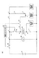
図1は、本発明の一実施形態である車両用電源装置100の構成図を示す。車両用電源装置100を備える車両は、複数の電気負荷を搭載しており、電圧系の異なる電気負荷が混在する。図1の場合、高圧系(例えば、42V系)の電気負荷(以下、「高圧系負荷」という)としてA,Bが例示され、低圧系(例えば、14V系)の電気負荷(以下、「低圧系負荷」という)として符号12が例示されている。
FIG. 1 shows a configuration diagram of a vehicle
電源のバックアップの要求が高圧系負荷Bより高い高圧系負荷Aの電源のバックアップを強化するため、高圧系負荷Aに対して高圧系電力を供給するための給電経路の数は、高圧系負荷Bに対して高圧系電力を供給するための給電経路より多い。図1の場合、高圧系負荷Aに対する給電経路は2経路あるが、高圧系負荷Bに対する給電経路は1経路である。高圧系負荷Aに対する給電経路として、給電経路73と給電経路74とがある。
In order to reinforce the backup of the power source of the high voltage system load A whose power source backup request is higher than that of the high voltage system load B, the number of power supply paths for supplying the high voltage system power to the high voltage system load A is There are more power supply paths for supplying high-voltage system power. In the case of FIG. 1, there are two power feeding paths for the high voltage system load A, but there are one power feeding paths for the high voltage system load B. There are a
高圧系負荷Aの具体例として、電動パワーステアリング装置や電動ブレーキ装置が挙げられる。 Specific examples of the high-voltage load A include an electric power steering device and an electric brake device.
電動パワーステアリング装置(以下、「電動パワステ」という)は、操舵状態に応じてモータにより操舵力を発生させてドライバーのステアリング操作を支援する。電動パワステは、操舵力調整用モータと操舵力調整用コンピュータ(電動パワステECU)とを備える。操舵力調整用モータは、例えば、ステアリング機構のラックのストロークを調整するモータである。電動パワステECUは、例えば、トルクセンサや操舵角センサなどからのセンサ信号に基づいて操舵力調整用モータの起動が必要と判断した場合、操舵力調整用モータの起動要求発生フラグを立てて、操舵力調整用モータを駆動する駆動信号を出力する。その駆動信号に従って操舵力調整用モータは動作する。操舵力調整用モータの動作によって、ドライバーのステアリング操作がアシストされ得る。 An electric power steering device (hereinafter referred to as “electric power steering”) supports a driver's steering operation by generating a steering force by a motor according to a steering state. The electric power steering includes a steering force adjusting motor and a steering force adjusting computer (electric power steering ECU). The steering force adjusting motor is, for example, a motor that adjusts the rack stroke of the steering mechanism. For example, when the electric power steering ECU determines that it is necessary to start the steering force adjusting motor based on a sensor signal from a torque sensor, a steering angle sensor, or the like, the electric power steering ECU sets a start request generation flag for the steering force adjusting motor to perform steering. A drive signal for driving the force adjusting motor is output. The steering force adjusting motor operates according to the drive signal. The driver's steering operation can be assisted by the operation of the steering force adjusting motor.
電動ブレーキ装置(以下、「電動ブレーキ」という)は、車両の挙動の安定性などの向上のため、横方向の加速度、ヨーレート、舵角などの車両の状態に応じて、車両の左右の制動力を自動的に調整する。電動ブレーキは、制動力調整用モータ(VSCモータ)と制動力調整用コンピュータ(VSC−ECU)とを備える。VSCモータは、制動力を調整するための油圧を調整するポンプを駆動するモータである。VSC−ECUは、例えば、車速センサ、加速度センサ、ヨーレートセンサ、舵角センサなどからのセンサ信号に基づいてVSCモータの起動が必要と判断した場合、VSCモータの起動要求発生フラグを立てて、VSCモータを駆動する駆動信号を出力する。その駆動信号に従ってVSCモータは動作する。VSCモータの動作によって、制動力が調整され得る結果、車両の挙動の安定化を可能にする。また、電動ブレーキ装置として、エンジンの吸気による負圧ではなく電動油圧ポンプによってドライバーの制動操作力をアシストする倍力装置(ハイドロブースタ)が挙げられる。 An electric brake device (hereinafter referred to as “electric brake”) is used to improve the vehicle's behavior stability, depending on the state of the vehicle such as lateral acceleration, yaw rate, rudder angle, etc. Adjust automatically. The electric brake includes a braking force adjusting motor (VSC motor) and a braking force adjusting computer (VSC-ECU). The VSC motor is a motor that drives a pump that adjusts the hydraulic pressure for adjusting the braking force. For example, when the VSC-ECU determines that the VSC motor needs to be started based on sensor signals from a vehicle speed sensor, an acceleration sensor, a yaw rate sensor, a rudder angle sensor, etc., the VSC-ECU sets a VSC motor start request generation flag, A drive signal for driving the motor is output. The VSC motor operates according to the drive signal. As a result of the braking force being able to be adjusted by the operation of the VSC motor, it is possible to stabilize the behavior of the vehicle. Further, as an electric brake device, there is a booster (hydro booster) that assists a driver's braking operation force with an electric hydraulic pump instead of a negative pressure due to engine intake.
一方、高圧系負荷Bの具体例として、ヘッドライト、シートヒータ、エアコンなどが挙げられる。また、低圧系負荷12の具体例として、エンジンスタータ、オーディオ、各種ECUなどが挙げられる。
On the other hand, specific examples of the high-voltage system load B include a headlight, a seat heater, and an air conditioner. Specific examples of the low-
また、車両用電源装置100は、高圧系の蓄電手段である高圧系蓄電池31と、低圧系の蓄電手段である低圧系蓄電池11と、高圧系の電圧を低圧系の電圧に降圧変換して高圧系から低圧系への電力供給を行う降圧モードと低圧系の電圧を高圧系の電圧に昇圧変換して低圧系から高圧系への電力供給を行う昇圧モードとを有する直流/直流電圧変換器20(DC−DCコンバータ20)とを備えている。
In addition, the vehicle
高圧系蓄電池31は高圧系の電圧で作動する高圧系負荷への電力供給に主に対応し、低圧系蓄電池11は低圧系の電圧で作動する低圧系負荷への電力供給に主に対応する。高圧系蓄電池31の具体例としてリチウムイオンバッテリがあり、低圧系蓄電池11の具体例として鉛バッテリがある。なお、高圧系蓄電池31や低圧系蓄電池11は、ニッケル水素電池、電気二重層キャパシタ、リチウムイオンバッテリ、鉛バッテリ、又はそれらのいずれかの組み合わせでもよい。
The high-
また、高圧系蓄電池31には、運動エネルギーを電気エネルギーに変換することにより発電を行うオルタネータ60が並列接続されている。オルタネータ60は、エンジンを動力源とする発電機であって、車両を走行させるためのエンジンの出力によって発電を行う。オルタネータ60で発生した電力によって、高圧系負荷が動作したり、高圧系蓄電池31が充電されたりする。オルタネータ60が停止している状態では、高圧系蓄電池31から各高圧系負荷に電力を供給し得る。例えば、エンジンが停止してオルタネータ60の不作動状態である駐車状態で必要とされる電力は、高圧系蓄電池31から供給することができる。
Further, an
DC−DCコンバータ20は、高圧系蓄電池31と低圧系蓄電池11との間に設けられ、その入出力電流の方向を双方向に変換可能な直流/直流電圧変換器である。DC−DCコンバータ20は、その高圧系側端子から入力される高圧系の電力を降圧変換して低圧系の電力としてその低圧系側端子から出力する、又は、その低圧系側端子から入力される低圧系の電力を昇圧変換して高圧系の電力としてその低圧系側端子から出力する。
The DC-
また、車両用電源装置100は、高圧系の給電状態を検出する電源マネジメントECU(以下、「パワマネECU」という)50を備える。パワマネECU50は、後述のバックアップ制御などの制御プログラムや制御データを記憶するROM、その制御プログラムの処理データを一時的に記憶するRAM及びその制御プログラムを処理するCPUなどを構成するマイクロコンピュータと、そのマイクロコンピュータと外部との情報をやりとりするための入出力インターフェースとを備える電子制御装置である。
Further, the vehicle
パワマネECU50は、高圧系の給電異常の判定をするため、高圧系蓄電池31の電圧を検出する電圧センサを用いて高圧系蓄電池31の電圧値を検出する。また、パワマネECU50は、例えば、高圧系蓄電池31の充放電電流を検出する電流センサや高圧系蓄電池31の電圧を検出する電圧センサを用いて高圧系蓄電池31の電流値や電圧値を検出することによって、高圧系蓄電池31の充電状態を検出してもよい。より具体的には、パワマネECU50は、高圧系蓄電池31の電流値や電圧値を検出することによって、高圧系蓄電池31の容量がどれだけ残っているのかを示す「充電率(SOC:State of Charge)」を算出する。充電率は、満充電容量に対する残容量を示すものである。パワマネECU50は、例えば、高圧系蓄電池31の充放電電流の積算(積分)などにより充電率(残容量)を算出する。電気量(高圧系蓄電池31の容量)の時間的変化の割合が、電流に相当するからである。残容量は高圧系蓄電池31の満充電時の容量から高圧系蓄電池31から放電された放電量を引いた値に相当することから、パワマネECU50は、高圧系蓄電池31の充放電電流をモニターしその履歴をメモリに記録することによって、充電率(残容量)を算出することが可能になる。なお、満充電時の初期容量は、所定のメモリに記憶されてよい。
The
また、パワマネECU50は、放電初期時の高圧系蓄電池31の電圧の極小値を測定することによって充電率を推定してもよい。放電初期時の電圧の落ち込みにより生ずる極小値と充電率は相関があることが知られているため、パワマネECU50は、その相関関係(例えば、マップデータ)に基づいて充電率を推定することができる。
The
また、パワマネECU50は、放電初期時の高圧系蓄電池31の内部抵抗を測定することによって充電率及び満充電容量を算出してもよい。内部抵抗は、初期放電電流と初期放電電圧によって算出される。内部抵抗と充電率、ならびに、内部抵抗と満充電容量は、相関があることが知られている。パワマネECU50は、高圧系蓄電池31の内部抵抗に対する充電率の算出マップを参照して、高圧系蓄電池31の内部抵抗に対応する充電率を算出する。パワマネECU50は、高圧系蓄電池31の内部抵抗に対する満充電容量の算出マップを参照して、高圧系蓄電池31の内部抵抗に対応する満充電容量を算出する。
The
パワマネECU50は、高圧系の給電状態に基づいて高圧系の給電異常の判定をする。パワマネECU50は、例えば、オルタネータ60による発電中に高圧系蓄電装置31が所定の充電状態を満たしていない場合には(例えば、蓄電装置11の電圧が所定電圧未満の場合には、又は蓄電装置11の充電率が所定値未満の場合には)、高圧系蓄電装置31が充電不良状態であるとして、高圧系の給電異常と判定する。
The
また、パワマネECU50は、例えば、高圧系の給電異常の一つとして高圧系蓄電装置31のオープン故障を検出してもよい。蓄電装置のオープン故障とは、蓄電装置の内部がオープン故障したり、蓄電装置のプラス端子やマイナス端子が外れたりすることである。蓄電装置の内部のオープン故障は、例えば、内部の機械的破損、腐食性物質の侵入、電解液の蒸発、経時劣化によるものである。一方、蓄電装置の端子外れとは、蓄電装置のプラス端子と電源ハーネスとの接続不良や蓄電装置のマイナス端子とGNDハーネスとの接続不良によるものである。蓄電装置のオープン故障が発生すると蓄電装置には電流が流れなくなる。そこで、パワマネECU50は、例えば、高圧系蓄電装置31の出力電流が電流センサによって略零であると検出された場合には、高圧系蓄電装置31がオープン故障状態であるとして、高圧系の給電異常と判定する。高圧系蓄電装置31の出力電流を検出するためには、図1の場合、高圧系蓄電装置31のプラス端子と高圧系電力を供給するための電源ハーネス上の点aとの間を流れる電流を検出すればよい。
Further, the
また、パワマネECU50は、例えば、高圧系蓄電装置31やオルタネータ60といった高圧系電源から高圧系負荷に高圧系電力を供給するための電源ハーネスを流れる電流(例えば、高圧系蓄電装置31と電源ハーネス上の点bとの間を流れる電流)が電流センサによって略零と検出された場合に、当該電源ハーネスが断線状態であるとして、高圧系の給電異常と判定してもよい。
The
また、パワマネECU50は、例えば、オルタネータ60の出力電圧が電圧センサによって所定値以下と検出された場合には、及び/又は、オルタネータ60の出力電流が電流センサによって所定値以下と検出された場合には、オルタネータ60が発電不良状態であるとして、高圧系の給電異常と判定してもよい。オルタネータ60の出力電流を検出するためには、図1の場合、オルタネータ60の出力端子と電源ハーネス上の点aとの間を流れる電流を検出すればよい。オルタネータ60の出力電圧を検出するためには、図1の場合、オルタネータ60の両端電圧を検出すればよい。
Further, the
パワマネECU50は、高圧系の給電異常と判定した場合、電源のバックアップを行うため、低圧系側を入力とし高圧系側を出力とする電圧変換方向となるようにDC−DCコンバータ20を制御するとともに、リレー81をオフにしてリレー82をオンにする。また、パワマネECU50は、高圧系の給電異常と判定した場合、バッテリリレー80をオフにしてもよい。高圧系の給電異常がオルタネータ60の発電不良状態のみであるならば、バッテリリレー80はオンのままでもよい。
The
リレー81は、DC−DCコンバータ20の高圧系側と電源ハーネス上の点bとを接続する給電経路72を遮断する手段である。給電経路72は、DC−DCコンバータ20の高圧系側に高圧系電源(高圧系蓄電装置31やオルタネータ60)からの出力電力を供給する手段である一方で、少なくとも高圧系負荷BにDC−DCコンバータ20の高圧系側からの出力電力を供給する手段である。また、リレー82は、DC−DCコンバータ20の高圧系側と高圧系負荷Aとを接続する給電経路73を遮断する手段である。給電経路73を介さずに高圧系電力を高圧系負荷Aに供給し得る給電経路74上に挿入されたダイオード7及び給電経路73が、高圧系負荷AのみにDC−DCコンバータ20の高圧系側からの出力電力を供給する手段に相当する。また、バッテリリレー80は、オルタネータ60や高圧系負荷などから構成される高圧系回路と高圧系蓄電池31との間の給電経路を遮断する手段である。リレー80,81,82は、オフにすることにより各給電経路は遮断され、オンにすることにより各給電経路は導通する。特に、リレー81の遮断により、DC−DCコンバータ20の高圧系側から高圧系負荷Bへの給電経路72による給電が制限される。リレー80,81,82は、半導体リレーでもメカリレーでもよい。
The
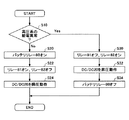
続いて、パワマネECU50による電源のバックアップ制御の動作について、図2を参照しながら説明する。
Next, the power backup control operation by the
図2は、パワマネECU50によるバックアップ制御の主要部分を示すフローである。パワマネECU50は、例えば、エンジンを始動させるためのイグニッションスイッチのオフからオンへの切り替えを検知した後に、図2に示されるバックアップ制御を実施する。パワマネECU50は、上述のように、高圧系の給電状態に基づいて高圧系の給電異常の判定をする(ステップ10)。
FIG. 2 is a flowchart showing a main part of the backup control by the
パワマネECU50は、高圧系の給電異常を示す状態が検出されていない状態では(ステップ10,No)、バッテリリレー80の状態をオンに保持するとともに(ステップ20)、リレー81の状態をオンにリレー82の状態をオフに保持する(ステップ22)。さらに、パワマネECU50は、高圧系側を入力とし低圧系側を出力とする降圧変換となるようにDC−DCコンバータ20を制御する(ステップ24)。このようにリレー80,81,82とDC−DCコンバータ20を制御することによって、DC−DCコンバータ20を介してオルタネータ60と高圧系蓄電池31といった高圧系電源からの高圧系電力を低圧系蓄電池11に充電することが可能になるとともに、DC−DCコンバータ20を介して高圧系電源からの高圧系電力を低圧系負荷12に給電することが可能になる。
The
一方、パワマネECU50は、高圧系の給電異常と判定した場合には(ステップ10,Yes)、電源のバックアップを行うため、リレー81の状態をオフにリレー82の状態をオンにするとともに(ステップ30)、低圧系側を入力とし高圧系側を出力とする昇圧変換となるようにDC−DCコンバータ20を制御する(ステップ32)。さらに、パワマネECU50は、バッテリリレー80をオフにしてもよい(ステップ34)。このようにリレー80,81,82とDC−DCコンバータ20を制御することによって、DC−DCコンバータ20の高圧系側からの出力電力を高圧系負荷Aのみに供給することができる。
On the other hand, when the
したがって、車両用電源装置100によれば、リレーと1つのDC−DCコンバータの簡易な構成で、高圧系の給電異常が発生しても、少なくとも高圧系負荷Aには低圧系蓄電池11からの給電を確保することが可能となる。また、高圧系蓄電池31に異常が生じたことにより正常な高圧系電源がオルタネータ60のみになった場合、その発電量よりも消費電力が上回るときには高圧系の電源電圧が低下し高圧系負荷の動作に支障が生ずるおそれがあるが、上述のように制御することによって、そのような高圧系電源の給電能力の不足を補うことができる。また、リレー81を遮断することによって、DC−DCコンバータ20を介して低圧系蓄電池11から供給される電力を高圧系負荷Bに供給されないようにすることができるので、高圧系負荷Bの消費電力にかかわらず、高圧系負荷Aに対しての給電を確実にバックアップすることができる。
Therefore, according to the vehicle
また、高圧系負荷Bより優先的な作動が要求される電気負荷を高圧系負荷Aに割り当てることによって、高圧系に給電異常が生じたとしても、そのような優先作動が要求される電気負荷に対する給電を確実にバックアップすることができる。すなわち、上述のように、電動パワステや電動ブレーキなどの車両の走行時の安全性にかかわるシステムを高圧系負荷Aに割り当てれば効果的である。 Moreover, even if a power supply abnormality occurs in the high-voltage system by assigning an electrical load that requires a higher priority operation than the high-voltage system load B to the high-voltage system load A, Power supply can be reliably backed up. That is, as described above, it is effective to assign a system related to safety during traveling of the vehicle such as an electric power steering and an electric brake to the high-voltage load A.
以上、本発明の好ましい実施例について詳説したが、本発明は、上述した実施例に制限されることはなく、本発明の範囲を逸脱することなく、上述した実施例に種々の変形及び置換を加えることができる。 The preferred embodiments of the present invention have been described in detail above. However, the present invention is not limited to the above-described embodiments, and various modifications and substitutions can be made to the above-described embodiments without departing from the scope of the present invention. Can be added.
例えば、リレー82をダイオードに置き換えてもよい。ダイオードのアノード側がDC−DCコンバータ20の高圧系側となるように置き換えればよい。これにより、リレー82をパワマネECU50は制御不要となるので、さらに簡素な構成で、電源のバックアップを行うことができる。
For example, the
また、高圧系負荷Aを備えるシステムの具体例として、電動パワステと電動ブレーキとを示したが、当該システムはこれらの装置に限られない。例えば、電動スタビリティコントロール装置(ロール角調整用モータとロール角調整用コンピュータ(電動スタビECU)とを備え、ロール角調整用モータの動作によって車両のロール角を調整する装置)、車高制御装置(車高調整用モータと車高調整用コンピュータとを備え、ユーザからの指令や車両の状態に応じて車両の高さを制御する装置)、二次空気供給装置(エアクリーナからの空気を排気ポートに送り込むポンプモータとポンプモータを制御するコンピュータとを備え、エアクリーナからの空気を排気ポートに送り込む装置)、カムバイワイヤ(エンジンカムを動かすカム用モータとカム用モータを制御するコンピュータとを備え、エンジンカムをベルトレスで制御する装置)などが挙げられる。 Moreover, although the electric power steering and the electric brake were shown as a specific example of the system provided with the high voltage | pressure system load A, the said system is not restricted to these apparatuses. For example, an electric stability control device (a device that includes a roll angle adjustment motor and a roll angle adjustment computer (electric stabilizer ECU) and adjusts the roll angle of the vehicle by the operation of the roll angle adjustment motor), a vehicle height control device (Equipped with a vehicle height adjusting motor and a vehicle height adjusting computer and controlling the height of the vehicle in accordance with a command from the user and the state of the vehicle), secondary air supply device (exhaust port for air from the air cleaner) A pump motor that feeds into the engine and a computer that controls the pump motor, a device that feeds air from the air cleaner into the exhaust port), a cam-by-wire (a cam motor that moves the engine cam and a computer that controls the cam motor, A device that controls the cam without a belt).
また、上述の実施例では、高圧系と低圧系の異なる電圧系を有する電源システムを示したが、高圧系と低圧系の電圧仕様が共通の電源システムであってもよい(例えば、図1の高圧系と低圧系が同じ42V系の電圧仕様)。この場合、DC−DCコンバータ20は、同圧変換の変換動作をするものであればよい。
In the above-described embodiment, the power supply system having the voltage system different from the high-voltage system and the low-voltage system is shown. However, the power supply system may have a common voltage specification for the high-voltage system and the low-voltage system (for example, FIG. High voltage system and low voltage system are the same 42V voltage specification). In this case, the DC-
また、DC−DCコンバータ20とパワマネECU50については、両者を別体構成にしてもよいし一体構成にしてもよい。
Further, the DC-
また、パワマネECU50の異常判定結果を車両の運転者等のユーザに知らせる報知手段を備えてもよい。報知手段として、スピーカや表示装置が挙げられる。表示装置は、例えば、その判定結果を表示するディスプレイや、その判定結果を点灯状態によって知らせるウォーニングランプであればよい。これにより、ユーザは高圧系の給電異常の発生を適切に認識することができる。 Moreover, you may provide the alerting | reporting means to notify users, such as a vehicle driver, of the abnormality determination result of power management ECU50. Examples of the notification means include a speaker and a display device. The display device may be, for example, a display that displays the determination result or a warning lamp that notifies the determination result by a lighting state. As a result, the user can appropriately recognize the occurrence of a high-voltage power supply abnormality.
また、本発明は、車両用電源装置に限らず、異なる電源間に直流/直流電圧変換器を備える他の用途の電源装置にも適用することができる。 In addition, the present invention is not limited to a vehicle power supply device, and can be applied to a power supply device for other purposes including a DC / DC voltage converter between different power supplies.
11 低圧系蓄電池
12 低圧系負荷
20 DC−DCコンバータ
31 高圧系蓄電池
50 電源マネジメントECU
60 オルタネータ
11 Low
60 Alternator
Claims (5)
第2の電圧系の第2電源と、
前記第1電源と前記第2電源との間に設けられる直流/直流電圧変換器と、
前記第1の電圧系の給電状態を検出する給電状態検出手段と、
前記第1の電圧系の電気負荷のうちの第1の電気負荷のみに前記直流/直流電圧変換器の前記第1の電圧系側からの出力電力を供給する第1の供給手段と、
前記第1の電圧系の電気負荷のうちの第2の電気負荷に前記直流/直流電圧変換器の前記第1の電圧系側からの出力電力を供給する第2の供給手段と、
前記給電状態検出手段によって前記第1の電圧系の異常を示す所定の給電異常状態が検出された場合に、前記第2の供給手段による給電を制限する給電制限手段とを備える、電源制御装置。 A first power supply of a first voltage system;
A second power source of a second voltage system;
A DC / DC voltage converter provided between the first power source and the second power source;
Power supply state detection means for detecting a power supply state of the first voltage system;
First supply means for supplying output power from the first voltage system side of the DC / DC voltage converter only to the first electrical load of the first voltage system electrical load;
Second supply means for supplying output power from the first voltage system side of the DC / DC voltage converter to a second electrical load of the first voltage system electrical load;
A power supply control device comprising: a power supply restricting unit configured to restrict power supply by the second supply unit when a predetermined power supply abnormality state indicating abnormality of the first voltage system is detected by the power supply state detection unit.
2. The power supply according to claim 1, wherein when the power feeding abnormality state is detected, the power on the second voltage system side is voltage-converted by the DC / DC voltage converter and supplied to the first electric load. Control device.
第2の電圧系の第2電源と、
前記第1電源と前記第2電源との間に設けられる直流/直流電圧変換器と、
前記第1の電圧系の給電状態を検出する給電状態検出手段と、
前記給電状態検出手段によって前記第1の電圧系の異常を示す所定の給電異常状態が検出された場合に、前記第1の電圧系の電気負荷のうちの所定の電気負荷に対する前記直流/直流電圧変換器からの給電を制限する給電制限手段とを備える、電源制御装置。 A first power supply of a first voltage system;
A second power source of a second voltage system;
A DC / DC voltage converter provided between the first power source and the second power source;
Power supply state detection means for detecting a power supply state of the first voltage system;
The DC / DC voltage with respect to a predetermined electric load among the electric loads of the first voltage system when a predetermined power supply abnormality state indicating an abnormality of the first voltage system is detected by the power supply state detection means. A power supply control device comprising: a power supply limiting unit that limits power supply from the converter.
Priority Applications (1)
| Application Number | Priority Date | Filing Date | Title |
|---|---|---|---|
| JP2007116018A JP2008278564A (en) | 2007-04-25 | 2007-04-25 | Power supply control device |
Applications Claiming Priority (1)
| Application Number | Priority Date | Filing Date | Title |
|---|---|---|---|
| JP2007116018A JP2008278564A (en) | 2007-04-25 | 2007-04-25 | Power supply control device |
Publications (1)
| Publication Number | Publication Date |
|---|---|
| JP2008278564A true JP2008278564A (en) | 2008-11-13 |
Family
ID=40055880
Family Applications (1)
| Application Number | Title | Priority Date | Filing Date |
|---|---|---|---|
| JP2007116018A Pending JP2008278564A (en) | 2007-04-25 | 2007-04-25 | Power supply control device |
Country Status (1)
| Country | Link |
|---|---|
| JP (1) | JP2008278564A (en) |
Cited By (28)
| Publication number | Priority date | Publication date | Assignee | Title |
|---|---|---|---|---|
| JP2011030363A (en) * | 2009-07-24 | 2011-02-10 | Toyota Industries Corp | Vehicle power supply unit |
| CN102107608A (en) * | 2009-12-24 | 2011-06-29 | 本田技研工业株式会社 | Power supply device for electric vehicle |
| WO2011121975A1 (en) * | 2010-03-31 | 2011-10-06 | パナソニック株式会社 | Power source device for vehicle |
| WO2011121974A1 (en) * | 2010-03-29 | 2011-10-06 | パナソニック株式会社 | Power supply device for vehicle |
| CN102729819A (en) * | 2012-06-20 | 2012-10-17 | 上海沿锋汽车科技有限公司 | Double-circuit voltage control device for ignition switch of electric vehicle |
| JP2012228051A (en) * | 2011-04-19 | 2012-11-15 | Mitsubishi Electric Corp | Power supply system for vehicle |
| CN102983740A (en) * | 2011-09-02 | 2013-03-20 | 笙科电子股份有限公司 | Power supply management system and method applied to satellite down converter |
| CN104054000A (en) * | 2012-01-12 | 2014-09-17 | 艾里逊变速箱公司 | System and method for high voltage cable detection in hybrid vehicles |
| JP2014217084A (en) * | 2013-04-22 | 2014-11-17 | 株式会社オートネットワーク技術研究所 | Power supply unit |
| JP2015061442A (en) * | 2013-09-19 | 2015-03-30 | 株式会社オートネットワーク技術研究所 | Transformer device |
| JP2015076959A (en) * | 2013-10-08 | 2015-04-20 | 株式会社オートネットワーク技術研究所 | Power system |
| JP2015077933A (en) * | 2013-10-18 | 2015-04-23 | 株式会社オートネットワーク技術研究所 | Vehicle power supply system |
| JP2015180140A (en) * | 2014-03-19 | 2015-10-08 | 三洋電機株式会社 | Power supply system for vehicle |
| JP2016037064A (en) * | 2014-08-05 | 2016-03-22 | トヨタ自動車株式会社 | On-vehicle power supply device |
| CN105620396A (en) * | 2016-04-07 | 2016-06-01 | 成都雅骏新能源汽车科技股份有限公司 | Feed system of electric automobile |
| WO2017159307A1 (en) * | 2016-03-18 | 2017-09-21 | 株式会社オートネットワーク技術研究所 | Power supply box |
| CN107472355A (en) * | 2017-07-06 | 2017-12-15 | 苏州汇川联合动力系统有限公司 | A kind of electric machine control system and method |
| WO2018008360A1 (en) * | 2016-07-07 | 2018-01-11 | 株式会社オートネットワーク技術研究所 | Relay device |
| WO2018123066A1 (en) * | 2016-12-29 | 2018-07-05 | 三菱電機株式会社 | Power conversion device |
| US20180215371A1 (en) * | 2017-01-31 | 2018-08-02 | Toyota Jidosha Kabushiki Kaisha | Electric power source system |
| CN109424399A (en) * | 2017-08-22 | 2019-03-05 | 通用汽车环球科技运作有限责任公司 | Dual power supply and control for electronic automatic transmission |
| JP2019193517A (en) * | 2018-04-27 | 2019-10-31 | 矢崎総業株式会社 | Power supply redundant system |
| JP2019195249A (en) * | 2018-04-27 | 2019-11-07 | 株式会社豊田自動織機 | Vehicle power supply system |
| JP2020063007A (en) * | 2018-10-19 | 2020-04-23 | 株式会社豊田自動織機 | Vehicle backup power supply device |
| CN111788094A (en) * | 2018-03-27 | 2020-10-16 | 日立汽车系统株式会社 | Brake device, electric brake device, and motor control device |
| CN113147503A (en) * | 2021-04-19 | 2021-07-23 | 北京汽车股份有限公司 | Electric vehicle power supply management method |
| CN117429285A (en) * | 2023-12-18 | 2024-01-23 | 宁波均胜新能源研究院有限公司 | Power battery charging circuit and control method thereof |
| WO2024048333A1 (en) * | 2022-08-31 | 2024-03-07 | パナソニックIpマネジメント株式会社 | Back-up power supply system and mobile body |
-
2007
- 2007-04-25 JP JP2007116018A patent/JP2008278564A/en active Pending
Cited By (56)
| Publication number | Priority date | Publication date | Assignee | Title |
|---|---|---|---|---|
| JP2011030363A (en) * | 2009-07-24 | 2011-02-10 | Toyota Industries Corp | Vehicle power supply unit |
| CN102107608A (en) * | 2009-12-24 | 2011-06-29 | 本田技研工业株式会社 | Power supply device for electric vehicle |
| CN102107608B (en) * | 2009-12-24 | 2015-06-17 | 本田技研工业株式会社 | Power supply device for electric vehicle |
| CN102811887A (en) * | 2010-03-29 | 2012-12-05 | 松下电器产业株式会社 | Power supply device for vehicle |
| JP5807180B2 (en) * | 2010-03-29 | 2015-11-10 | パナソニックIpマネジメント株式会社 | Vehicle power supply |
| WO2011121974A1 (en) * | 2010-03-29 | 2011-10-06 | パナソニック株式会社 | Power supply device for vehicle |
| JP5799251B2 (en) * | 2010-03-31 | 2015-10-21 | パナソニックIpマネジメント株式会社 | Vehicle power supply |
| CN102823103B (en) * | 2010-03-31 | 2015-03-11 | 松下电器产业株式会社 | Power source device for vehicle |
| US20130026828A1 (en) * | 2010-03-31 | 2013-01-31 | Panasonic Corporation | Power source device for vehicle |
| WO2011121975A1 (en) * | 2010-03-31 | 2011-10-06 | パナソニック株式会社 | Power source device for vehicle |
| JPWO2011121975A1 (en) * | 2010-03-31 | 2013-07-04 | パナソニック株式会社 | Vehicle power supply |
| US9071081B2 (en) | 2010-03-31 | 2015-06-30 | Panasonic Intellectual Property Management Co., Ltd. | Power source device for vehicle |
| CN102823103A (en) * | 2010-03-31 | 2012-12-12 | 松下电器产业株式会社 | Power source device for vehicle |
| US9018894B2 (en) | 2011-04-19 | 2015-04-28 | Mitsubishi Electric Corporation | Vehicular power supply system |
| DE102011084777B4 (en) * | 2011-04-19 | 2016-04-28 | Mitsubishi Electric Corporation | Vehicle power supply system |
| JP2012228051A (en) * | 2011-04-19 | 2012-11-15 | Mitsubishi Electric Corp | Power supply system for vehicle |
| CN102983740A (en) * | 2011-09-02 | 2013-03-20 | 笙科电子股份有限公司 | Power supply management system and method applied to satellite down converter |
| CN104054000A (en) * | 2012-01-12 | 2014-09-17 | 艾里逊变速箱公司 | System and method for high voltage cable detection in hybrid vehicles |
| US9581635B2 (en) | 2012-01-12 | 2017-02-28 | Allison Transmission, Inc. | System and method for high voltage cable detection in hybrid vehicles |
| CN102729819A (en) * | 2012-06-20 | 2012-10-17 | 上海沿锋汽车科技有限公司 | Double-circuit voltage control device for ignition switch of electric vehicle |
| JP2014217084A (en) * | 2013-04-22 | 2014-11-17 | 株式会社オートネットワーク技術研究所 | Power supply unit |
| JP2015061442A (en) * | 2013-09-19 | 2015-03-30 | 株式会社オートネットワーク技術研究所 | Transformer device |
| JP2015076959A (en) * | 2013-10-08 | 2015-04-20 | 株式会社オートネットワーク技術研究所 | Power system |
| JP2015077933A (en) * | 2013-10-18 | 2015-04-23 | 株式会社オートネットワーク技術研究所 | Vehicle power supply system |
| JP2015180140A (en) * | 2014-03-19 | 2015-10-08 | 三洋電機株式会社 | Power supply system for vehicle |
| JP2016037064A (en) * | 2014-08-05 | 2016-03-22 | トヨタ自動車株式会社 | On-vehicle power supply device |
| WO2017159307A1 (en) * | 2016-03-18 | 2017-09-21 | 株式会社オートネットワーク技術研究所 | Power supply box |
| CN105620396A (en) * | 2016-04-07 | 2016-06-01 | 成都雅骏新能源汽车科技股份有限公司 | Feed system of electric automobile |
| WO2018008360A1 (en) * | 2016-07-07 | 2018-01-11 | 株式会社オートネットワーク技術研究所 | Relay device |
| JP2018006252A (en) * | 2016-07-07 | 2018-01-11 | 株式会社オートネットワーク技術研究所 | Relay device |
| US10861663B2 (en) | 2016-07-07 | 2020-12-08 | Autonetworks Technologies, Ltd. | Relay device and a method to detect open-circuit failures |
| CN108604516B (en) * | 2016-07-07 | 2020-03-13 | 株式会社自动网络技术研究所 | Relay device |
| CN108604516A (en) * | 2016-07-07 | 2018-09-28 | 株式会社自动网络技术研究所 | Relay-set |
| JPWO2018123066A1 (en) * | 2016-12-29 | 2018-12-27 | 三菱電機株式会社 | Power converter |
| WO2018123066A1 (en) * | 2016-12-29 | 2018-07-05 | 三菱電機株式会社 | Power conversion device |
| US11183929B2 (en) | 2016-12-29 | 2021-11-23 | Mitsubishi Electric Corporation | DC-DC power conversion device having battery control |
| US10611360B2 (en) | 2017-01-31 | 2020-04-07 | Toyota Jidosha Kabushiki Kaisha | Electric power source system |
| JP2018122697A (en) * | 2017-01-31 | 2018-08-09 | トヨタ自動車株式会社 | Power source system |
| US20180215371A1 (en) * | 2017-01-31 | 2018-08-02 | Toyota Jidosha Kabushiki Kaisha | Electric power source system |
| CN108382205B (en) * | 2017-01-31 | 2021-06-22 | 丰田自动车株式会社 | Power supply system |
| CN108382205A (en) * | 2017-01-31 | 2018-08-10 | 丰田自动车株式会社 | Power-supply system |
| CN107472355A (en) * | 2017-07-06 | 2017-12-15 | 苏州汇川联合动力系统有限公司 | A kind of electric machine control system and method |
| CN109424399A (en) * | 2017-08-22 | 2019-03-05 | 通用汽车环球科技运作有限责任公司 | Dual power supply and control for electronic automatic transmission |
| CN109424399B (en) * | 2017-08-22 | 2021-05-18 | 通用汽车环球科技运作有限责任公司 | Dual power supply and control for an electronically controlled automatic transmission |
| CN111788094A (en) * | 2018-03-27 | 2020-10-16 | 日立汽车系统株式会社 | Brake device, electric brake device, and motor control device |
| JPWO2019187805A1 (en) * | 2018-03-27 | 2020-12-17 | 日立オートモティブシステムズ株式会社 | Brake device, electric brake device, and motor control device |
| JP7076532B2 (en) | 2018-03-27 | 2022-05-27 | 日立Astemo株式会社 | Brake device, electric brake device, and motor control device |
| JP2019193517A (en) * | 2018-04-27 | 2019-10-31 | 矢崎総業株式会社 | Power supply redundant system |
| JP2019195249A (en) * | 2018-04-27 | 2019-11-07 | 株式会社豊田自動織機 | Vehicle power supply system |
| JP7107159B2 (en) | 2018-10-19 | 2022-07-27 | 株式会社豊田自動織機 | Vehicle backup power supply |
| JP2020063007A (en) * | 2018-10-19 | 2020-04-23 | 株式会社豊田自動織機 | Vehicle backup power supply device |
| CN113147503A (en) * | 2021-04-19 | 2021-07-23 | 北京汽车股份有限公司 | Electric vehicle power supply management method |
| CN113147503B (en) * | 2021-04-19 | 2024-03-08 | 北京汽车股份有限公司 | Power management method for electric vehicle |
| WO2024048333A1 (en) * | 2022-08-31 | 2024-03-07 | パナソニックIpマネジメント株式会社 | Back-up power supply system and mobile body |
| CN117429285A (en) * | 2023-12-18 | 2024-01-23 | 宁波均胜新能源研究院有限公司 | Power battery charging circuit and control method thereof |
| CN117429285B (en) * | 2023-12-18 | 2024-03-26 | 宁波均胜新能源研究院有限公司 | Power battery charging circuit and control method thereof |
Similar Documents
| Publication | Publication Date | Title |
|---|---|---|
| JP2008278564A (en) | Power supply control device | |
| JP4258534B2 (en) | Power system | |
| JP4835690B2 (en) | Power supply | |
| JP4461824B2 (en) | Vehicle, vehicle control method, and computer-readable recording medium recording a program for causing a computer to execute the control method | |
| JP2008072880A (en) | Power supply system | |
| JP5640950B2 (en) | Vehicle control device | |
| WO2015015743A1 (en) | Vehicular power source system | |
| JP6598542B2 (en) | Power supply device and control method of power supply device | |
| KR20150136011A (en) | Electric power supply control device and electric power supply control method | |
| JP5430265B2 (en) | Control device for idle stop car | |
| JP5696585B2 (en) | Vehicle power supply control device | |
| JP2006213273A (en) | Power supply control device | |
| JP2008289303A (en) | Power controller | |
| CN112041200A (en) | On-vehicle backup circuit and on-vehicle backup device | |
| JP2007237856A (en) | Vehicular power supply system | |
| JP2010207061A (en) | Power supply system for vehicle | |
| CN108463737B (en) | Vehicle-mounted power supply system and state detection method of battery contained in vehicle-mounted power supply system | |
| JP2010081762A (en) | Vehicle power supply | |
| JP6969505B2 (en) | In-vehicle power control device and in-vehicle power supply system | |
| JP2007236132A (en) | Controller for vehicle | |
| CN108382205A (en) | Power-supply system | |
| JP2008131773A (en) | Capacitor device | |
| JP2008131772A (en) | Power supply unit | |
| JP5134838B2 (en) | Vehicle power supply | |
| JP2007153149A (en) | Vehicular power supply control device |