JP2008261750A - Pressure sensor, and diaphragm for pressure sensor - Google Patents
Pressure sensor, and diaphragm for pressure sensor Download PDFInfo
- Publication number
- JP2008261750A JP2008261750A JP2007105146A JP2007105146A JP2008261750A JP 2008261750 A JP2008261750 A JP 2008261750A JP 2007105146 A JP2007105146 A JP 2007105146A JP 2007105146 A JP2007105146 A JP 2007105146A JP 2008261750 A JP2008261750 A JP 2008261750A
- Authority
- JP
- Japan
- Prior art keywords
- pressure
- diaphragm
- receiving portion
- pressure receiving
- pressure sensor
- Prior art date
- Legal status (The legal status is an assumption and is not a legal conclusion. Google has not performed a legal analysis and makes no representation as to the accuracy of the status listed.)
- Withdrawn
Links
Images


Landscapes
- Measuring Fluid Pressure (AREA)
Abstract
Description
本発明は、ダイヤフラム方式の圧力センサおよび圧力センサ用ダイヤフラムに関するものである。 The present invention relates to a diaphragm type pressure sensor and a diaphragm for a pressure sensor.
圧力センサには、ダイヤフラムを用いたものがある。このダイヤフラム式の圧力センサは、ダイヤフラムの受圧部の両面に加わる圧力の差によってこの受圧部が撓むので、この受圧部が撓むことを利用して圧力を測定している。そしてダイヤフラム式の圧力センサについて開示したものには特許文献1がある。特許文献1に開示された圧力センサは2つの水晶ダイヤフラムを備えており、これらのダイヤフラムが互いに接合して内側に双音叉振動子を配設する空間を形成している。この双音叉振動子は、ベース側のダイヤフラムに配設してある。すなわち双音叉振動子は、その両端部をベース側のダイヤフラムに接合しており、双音叉振動子を構成する振動腕の長辺方向がダイヤフラムの平面方向に沿っている。そしてダイヤフラムが圧力を受けて湾曲すると、これに伴って双音叉振動子も湾曲する。双音叉振動子には、伸張または圧縮のストレスが加わるので、発振周波数が変化する。圧力センサは、この発振周波数の変化から圧力等を測定している。
ところで前述した水晶ダイヤフラムの材料となる水晶結晶には、結晶構造の欠陥(線状欠陥)が存在する場合がある。そして水晶ダイヤフラムは、ウエットエッチングにより形成することができるが、水晶結晶に線状欠陥が存在していると、この線状欠陥の部分が選択的にエッチングされてしまうエッチチャネルが生じる。これにより水晶ダイヤフラムには、部分的に極端に薄い箔肉部が形成されてしまったり、水晶ダイヤフラムの上下面を貫通する孔が形成されてしまったりする。 By the way, a crystal crystal serving as the material of the above-described crystal diaphragm may have a crystal structure defect (linear defect). The quartz diaphragm can be formed by wet etching. However, if a linear defect exists in the quartz crystal, an etch channel is formed in which the portion of the linear defect is selectively etched. As a result, an extremely thin foil portion is formed in the quartz diaphragm partially, or a hole penetrating the upper and lower surfaces of the quartz diaphragm is formed.
水晶ダイヤフラムに箔肉部が存在する場合、圧力センサが完成した段階では2枚の水晶ダイヤフラムを積層方向に接合して形成する内部空間の気密が保たれているために、この箔肉部を発見することが困難である。この場合、この圧力センサを使用している時に衝撃等が加わると箔肉部に孔があき、内部空間の気密性が失われてしまう。また水晶ダイヤフラムに貫通孔が存在する場合、この貫通孔は小さい孔なので、例えば圧力センサを加圧しても貫通孔から内部空間内に出入する気体の量がごく僅かであり、特性検査のみでは完全に貫通孔を発見することが困難である。 When a foil part exists in the quartz diaphragm, it was discovered when the pressure sensor was completed because the internal space formed by joining two quartz diaphragms in the stacking direction was kept airtight. Difficult to do. In this case, when an impact or the like is applied while using this pressure sensor, a hole is formed in the foil portion, and the airtightness of the internal space is lost. In addition, if there is a through hole in the quartz diaphragm, this through hole is a small hole. For example, even if the pressure sensor is pressurized, the amount of gas entering and leaving the internal space from the through hole is very small. It is difficult to find a through hole.
なおこのようなトラブルを未然に防止する方法としては、図5に示すように、圧力センサ1全体を凹状の容器2内に入れ、容器2内にポッティング樹脂3を充填することでエッチチャネル全体を覆ってしまえばよい。しかし、この方法では容器2が必要になるので大型になってしまう。またポッティング樹脂3を容器2内に充填するときは、容器2内に圧力センサ1を配置した後、凹状の開口部からポッティング樹脂3を注入することになる。しかし、この方法では、圧力センサ1と容器2の底面(凹状の底面)との間にポッティング樹脂3が流れ込み難く、気泡が発生してしまう。この気泡が存在していると、温度が上昇したときに気泡が膨張するので、圧力センサ1は気泡が膨張したときの応力を受けてしまい、正確な圧力を測定できなくなってしまう。また気泡が存在していると、ダイヤフラムを保護すべきポッティング樹脂3に欠陥が有る状態になるため、ダイヤフラムを適切に保護できない。すなわち内部空間4の気密性を確保できない。さらにポッティング樹脂3を熱硬化させる際には、圧力センサ1と容器2の底面との間が閉鎖状態にあるため、素早く有機溶剤を揮発することができず、未硬化になってしまったり、気泡が存在したまま硬化してしまう。
As a method for preventing such troubles, as shown in FIG. 5, the entire pressure channel 1 is placed in a
本発明は、センサ素子片の気密性を確保した圧力センサおよび圧力センサ用ダイヤフラムを提供することを目的とする。 An object of this invention is to provide the pressure sensor and the diaphragm for pressure sensors which ensured the airtightness of the sensor element piece.
本発明に係る圧力センサは、測定対象となる圧力を受ける受圧部と、受圧部の一方の面を覆う保護材と、受圧部の他方の面に配設され、受圧部が撓むのに伴って変形するセンサ素子片とを有することを特徴としている。保護材により受圧部を補強できるので、センサ素子片の気密性を確保できる。すなわち受圧部に極めて薄い部分が存在している場合でも、この部分を保護材で補強できる。また受圧部に直径の極めて小さい貫通孔が存在している場合でも、この貫通孔を保護材で封止できる。このため圧力センサに衝撃等が加わっても、保護材で補強された受圧部に孔があくことを防止できるとともに、センサ素子片を気密封止している状態を維持できる。よって圧力センサは、受圧部に欠陥が存在していても、圧力測定を続けることができる。 A pressure sensor according to the present invention is provided on a pressure receiving portion that receives pressure to be measured, a protective material that covers one surface of the pressure receiving portion, and the other surface of the pressure receiving portion, and as the pressure receiving portion bends. And a sensor element piece that deforms. Since the pressure receiving portion can be reinforced by the protective material, the airtightness of the sensor element piece can be ensured. That is, even when a very thin portion exists in the pressure receiving portion, this portion can be reinforced with a protective material. Further, even when a through hole having a very small diameter exists in the pressure receiving portion, the through hole can be sealed with a protective material. For this reason, even if an impact or the like is applied to the pressure sensor, it is possible to prevent the pressure receiving portion reinforced with the protective material from being perforated and maintain the state where the sensor element piece is hermetically sealed. Therefore, the pressure sensor can continue the pressure measurement even if the pressure receiving portion has a defect.
また本発明に係る圧力センサは、受圧部の周囲に支持部を有し、受圧部の一方の面と支持部との間に、受圧部の一方の面が低くなる段差を設けて、凹部を形成してなり、凹部内に保護材を設けたことを特徴としている。凹部によって受圧部から保護材が流れ出るのを防止できる。また凹部の高さを調整することにより、受圧部を覆う保護材の厚さを制御できるとともに、受圧部を覆う最低限の保護材の厚さを確保できる。 In addition, the pressure sensor according to the present invention has a support portion around the pressure receiving portion, and a recess is provided between the one surface of the pressure receiving portion and the support portion so that one surface of the pressure receiving portion is lowered. It is formed, and a protective material is provided in the recess. The protective material can be prevented from flowing out of the pressure receiving portion by the concave portion. Further, by adjusting the height of the recess, the thickness of the protective material covering the pressure receiving portion can be controlled, and the minimum thickness of the protective material covering the pressure receiving portion can be secured.
そして前述した保護材は、ゲル状になっていることを特徴としている。これにより保護材は、受圧部が撓むのを阻害し難くなり、圧力センサへの悪影響を低減できる。 The protective material described above is characterized by being in a gel form. Thereby, it becomes difficult for a protective material to inhibit that a pressure receiving part bends, and it can reduce the bad influence to a pressure sensor.
また本発明に係る圧力センサは、受圧部を備えたダイヤフラムを積層方向に2枚重ねて配設し、ダイヤフラム同士の間に設けた空間内における一方のダイヤフラムにセンサ素子片を配設したことを特徴としている。これにより受圧部に欠陥があったとしても、一方のダイヤフラムと他方のダイヤフラムとの間に形成された空間の気密状態を維持できる。よって圧力センサは圧力を測定できる。 In the pressure sensor according to the present invention, two diaphragms each having a pressure receiving portion are arranged in the stacking direction, and the sensor element piece is arranged on one diaphragm in a space provided between the diaphragms. It is a feature. Thereby, even if there is a defect in the pressure receiving portion, the airtight state of the space formed between one diaphragm and the other diaphragm can be maintained. Therefore, the pressure sensor can measure the pressure.
また本発明に係る圧力センサは、受圧部を備えたダイヤフラムと、基板部とを重ねて配設し、ダイヤフラムと基板部との間に設けた空間内にセンサ素子片を配設したことを特徴としている。これにより受圧部に欠陥があったとしても、ダイヤフラムと基板部との間に形成された空間の気密状態を維持できる。よって圧力センサは、ダイヤフラムにおける一方の面に加わる圧力と、他方の面に加わる圧力との圧力差によって、圧力を測定できる。 The pressure sensor according to the present invention is characterized in that a diaphragm having a pressure receiving portion and a substrate portion are disposed so as to overlap each other, and a sensor element piece is disposed in a space provided between the diaphragm and the substrate portion. It is said. Thereby, even if there is a defect in the pressure receiving portion, the airtight state of the space formed between the diaphragm and the substrate portion can be maintained. Therefore, the pressure sensor can measure the pressure by the pressure difference between the pressure applied to one surface of the diaphragm and the pressure applied to the other surface.
また本発明に係る圧力センサは、センサ素子片に発振回路が接続し、発振回路に周波数測定演算手段が接続したことを特徴としている。これにより圧力センサは圧力値を得ることができる。 The pressure sensor according to the present invention is characterized in that an oscillation circuit is connected to the sensor element piece, and a frequency measurement calculation means is connected to the oscillation circuit. Thereby, the pressure sensor can obtain a pressure value.
また本発明に係る圧力センサ用ダイヤフラムは、一方の面と他方の面とに加わる圧力差によって変形し、且つ、水晶によって形成された受圧部を有し、受圧部の他方の面にゲル状の保護材を設けたことを特徴としている。これにより保護材によって受圧部を補強できる。すなわち受圧部に極めて薄い部分が存在している場合でも、この部分を保護材で補強できる。また受圧部に直径の極めて小さい貫通孔が存在している場合でも、この貫通孔を保護材で封止できる。 The diaphragm for a pressure sensor according to the present invention is deformed by a pressure difference applied to one surface and the other surface, and has a pressure receiving portion formed of crystal, and has a gel-like shape on the other surface of the pressure receiving portion. It features a protective material. Thereby, a pressure receiving part can be reinforced with a protective material. That is, even when a very thin portion exists in the pressure receiving portion, this portion can be reinforced with a protective material. Further, even when a through hole having a very small diameter exists in the pressure receiving portion, the through hole can be sealed with a protective material.
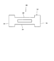
以下に、本発明に係る圧力センサおよび圧力センサ用ダイヤフラムの実施形態について説明する。まず第1の実施形態について説明する。図1は第1の実施形態に係る圧力センサの断面図である。圧力センサ10は、2枚のダイヤフラム14(14a,14b)と、ダイヤフラム14に設けた保護材12と、2枚のダイヤフラム14を重ねることによって形成される内部空間28に設けたセンサ素子片30とを有している。
Embodiments of a pressure sensor and a pressure sensor diaphragm according to the present invention will be described below. First, the first embodiment will be described. FIG. 1 is a cross-sectional view of a pressure sensor according to the first embodiment. The pressure sensor 10 includes two diaphragms 14 (14a, 14b), a
具体的には、各ダイヤフラム14は、測定対象となる圧力を受けて一方の面16aと他方の面16bに加わる圧力差によって湾曲する受圧部16と、受圧部16の周囲に設けた支持部18とを備えている。受圧部16は支持部18よりも薄くなっており、各ダイヤフラム14の上面および下面にそれぞれ凹部20,22が形成してある。すなわちダイヤフラム14は、ダイヤフラム14同士を接合したときに外側となる面(外面)に段差となる第1凹部20を備えるとともに、ダイヤフラム14同士が向かい合う面(内面)に第2凹部22を備えている。そして受圧部16は、第1凹部20および第2凹部22の各底面となる部分によって形成している。したがって受圧部16と支持部18との間に段差を設けて、受圧部16が支持部18よりも薄くなるようにしてある。
Specifically, each
また2つあるダイヤフラム14のうちの一方(図1の下側に示す一方のダイヤフラム14a)には、センサ素子片30を配設できるように、第2凹部22の底面に固着部24を設けている。すなわち一方のダイヤフラム14aは、他方のダイヤフラム14b(図1の上に示すダイヤフラム14)に対面する受圧部16に固着部24を備えている。この固着部24は、センサ素子片30の両端を支持できるように1対設けてあり、且つ、センサ素子片30の中央部が受圧部16の中心に来るように設けてある。
Further, one of the two diaphragms 14 (one diaphragm 14a shown in the lower side of FIG. 1) is provided with a fixing
また一方のダイヤフラム14aにおける第2凹部22に連結部26が設けてある。連結部26は、第2凹部22の底面から垂直方向に突き出た形状になっている。そして連結部26は、一方のダイヤフラム14aと他方のダイヤフラム14bが接合したときに、他方のダイヤフラム14bの受圧部16(第2凹部22)に接合するようになっている。このような連結部26は、1つ以上設けてあればよい。そして2つの連結部26を一方のダイヤフラム14aに設けるときは、例えば、一方のダイヤフラム14aの中心点を通る直線上に各連結部26を配設するとともに、一方のダイヤフラム14aに接合されているセンサ素子片30を挟み込むように配設してあればよい。
Further, a connecting
そして一方のダイヤフラム14aと他方のダイヤフラム14bは、各第2凹部22を向かい合わせつつ、支持部18同士を接合している。これによりダイヤフラム14の内側には、センサ素子片30を収容する空間28が形成される。この空間28は、気密封止されるようになっている。
The one diaphragm 14a and the
なお各ダイヤフラム14は平面視して同じ形状になっていればよく、特に平面形状が限定されることがない。このため各ダイヤフラム14の平面形状は、例えば円形や矩形等になっていればよい。
In addition, each
また保護材12は、圧力センサ10の外側部分における受圧部16の表面、すなわち各ダイヤフラム14の第1凹部20に設けてある。この保護材12は、受圧部16を覆っている。保護材12は可撓性に優れており、受圧部16が圧力を受けたときに、受圧部16の撓み機能を低下させないものである。例えば、保護材12は、硬化した後にゲル状になっているものであればよく、より具体的な一例としてはシリコーンゲルであればよい。
Further, the
またセンサ素子片30は、次のようになっている。図2はセンサ素子片の概略平面図である。なお図2では、センサ素子片に設けられる電極の記載を省略している。センサ素子片30は、図2に一例を示すように、双音叉振動片32となっている。すなわちセンサ素子片30は2本の振動腕34を有しており、これらの振動腕34の両端に基部36を備えている。そして励振電極(図示せず)が各振動腕34に設けてあるとともに、接続パターン(図示せず)を介して前記励振電極に導通したマウント電極(図示せず)が基部36に設けてある。この前記励振電極、前記マウント電極および前記接続パターンは、正と負の極性を有するように1対設けられている。そしてセンサ素子片30に電気信号(駆動信号)を供給すると、この駆動信号が前記マウント電極および前記接続パターンを介して前記励振電極に供給され、2つの振動腕34が互いに近づいたり離れたりする屈曲振動を行う。
The
このようなセンサ素子片30を一方のダイヤフラム14aに配設するには、センサ素子片30の基部36と一方のダイヤフラム14aの固着部24とを接合材(図示せず)で固着すればよい。具体的には、前記接合材として導電性接着剤を用いて基部36と固着部24を接合するとともに、前記導電性接着剤を介して前記マウント電極と一方のダイヤフラム14aに設けた配線パターン(図示せず)とを導通すればよい。またその他の具体例としては、前記接合材を用いて基部36と固着部24を接合するとともに、前記マウント電極と前記配線パターンとにワイヤを接合して導通すればよい。
In order to arrange such a
そして圧力センサ10は、センサ回路を備えている。図3はセンサ回路のブロック図である。センサ回路40は、発振回路42と周波数測定演算手段44を備えている。発振回路42は、入力側がセンサ素子片30に接続している。この発振回路42は、センサ素子片30に駆動信号を供給して発振・増幅させる回路である。また周波数測定演算手段44は、入力側が発振回路42に接続している。周波数測定演算手段44は、発振回路42から出力する信号の周波数、すなわちセンサ素子片30の発振周波数を測定し、この測定結果から圧力を求めるものである。
The pressure sensor 10 includes a sensor circuit. FIG. 3 is a block diagram of the sensor circuit. The
このような圧力センサ10は、次のようにして製造することができる。まずダイヤフラム14の材料として水晶等を用いる場合は、ダイヤフラム14をエッチングにより形成する。すなわち水晶素板の表面にマスクを被せ、このマスクの開口部分の水晶素板をエッチングすることによりダイヤフラム14を得る。これにより受圧部16の一方の面16aと支持部18との間に段差が形成されて、第1凹部20を得る。また受圧部16の他方の面16bと支持部18との間に段差が形成されて、第2凹部22を得る。そしてエッチング時間等を始めとするエッチング条件を適宜設定することにより、凹部20,22の深さ等を正確に制御できる。このためダイヤフラム14は生産性に優れ、またダイヤフラム14の個体差が生じ難いので、各圧力センサ10の特性が均一になる。なお一方のダイヤフラム14aおよび他方のダイヤフラム14bのいずれもエッチングにより形成できる。
Such a pressure sensor 10 can be manufactured as follows. First, when using quartz or the like as the material of the
次に、一方のダイヤフラム14aの固着部24にセンサ素子片30を配設する。この後、各ダイヤフラム14の第2凹部22を向かい合わせて、一方のダイヤフラム14aと他方のダイヤフラム14bを接合する。このとき各ダイヤフラム14も支持部18同士が接合するので、一方のダイヤフラム14aと他方のダイヤフラム14bの間に形成されている空間28内にセンサ素子片30が配置してある。
Next, the
そして受圧部16における圧力センサ10の外側となる面に保護材12を設ける。これは、まず一方のダイヤフラム14aおよび他方のダイヤフラム14bにそれぞれ設けた第1凹部20のどちらか一方に保護材12(ポッティング樹脂)を充填し、硬化する。これにより受圧部16の外面がゲル状の保護材12によって覆われる。この後、前記の工程により保護材12を充填した第1凹部20とは反対側のものに、保護材12を充填し硬化する。これにより受圧部16の外面がゲル状の保護材12によって覆われる。
The
なお保護材12は、第1凹部20の内部に注入されるので、この第1凹部20の高さによって保護材12の高さを調整することができる。すなわち、前述したように第1凹部20をエッチングで形成すれば、この第1凹部20の高さを正確に制御できるので、第1凹部20の全てが満たされるまで保護材12を注入すれば、保護材12の厚さに個体差がでることはない。よって受圧部16を保護するのに必要な保護材12の厚さを求めておき、この保護材12の厚さを実現できるように第1凹部20の高さを設定しておけば、その後、第1凹部20を全て満たすように保護材12を充填するだけで所望の保護材12の厚さを確実に得る。そして第1凹部20の高さを変更するだけで、第1凹部20に充填される保護材12の量を調整できる。また第1凹部20により、受圧部16から保護材12が流れ出るのを防いでいる。
Since the
この後、ダイヤフラム14の側面に設けてある封止用の孔(図示せず)を用いて、接合しているダイヤフラム14の間に形成した空間28を真空にする。そして、前記空間28を所定の真空度にした後、前記封止用の孔を封止する。これにより前記空間28が気密封止され、センサ素子片30が真空中で発振することになる。
Thereafter, the
次に、圧力センサ10の作用について説明する。まず圧力を測定する環境に圧力センサ10を配置する。そして圧力センサ10を駆動する。すなわち発振回路42からセンサ素子片30に駆動信号を供給して、これらの間で信号を増幅・発振させる。そして発振回路42は、センサ素子片30が屈曲振動するときの周波数と同じ周波数となっている電気信号(検出信号)を周波数測定演算手段44へ出力する。周波数測定演算手段44は、検出信号の周波数を測定する。
Next, the operation of the pressure sensor 10 will be described. First, the pressure sensor 10 is arranged in an environment for measuring pressure. Then, the pressure sensor 10 is driven. That is, a drive signal is supplied from the oscillation circuit 42 to the
そして圧力センサ10の外部、すなわちダイヤフラム14の受圧部16に加わる圧力P1が、圧力センサ10の内部、すなわちセンサ素子片30が収容されている空間28の圧力P2と同じ場合は、受圧部16に変化が生じてない。このとき周波数測定演算手段44では、検出信号の周波数f0を測定する。周波数測定演算手段44は、予め記憶してある基準周波数と周波数f0を比較して、両周波数間に新たに差が生じないので、予め登録してある周波数f0に応じた圧力値を出力する。具体的な一例としては、基準周波数としてP1=P2のときの検出信号の周波数f0を周波数測定演算手段44に予め登録しておき、基準周波数f0と検出された周波数f0との差分を求め、この差分が零であるから、予め1対1に登録してある基準周波数f0ときの圧力値を出力する。
If the pressure P1 applied to the outside of the pressure sensor 10, that is, the
また圧力センサ10外部の圧力P1が圧力センサ10内部の圧力P2よりも大きくなった場合、保護材12を介して受圧部16に加わる圧力P1によって、圧力センサ10の内部に向かって受圧部16が湾曲(変形)する。なお保護材12は可撓性を有しているので、受圧部16が湾曲するのを阻害することがない。そして受圧部16が撓むのに伴って、センサ素子片30も変形する。すなわち受圧部16が湾曲すると、受圧部16に両端を固定してあるセンサ素子片30の振動腕34も他方のダイヤフラム14bへ向けて湾曲する。このとき振動腕34の中央部が基部36に比べて圧力センサ10の内側へ湾曲する。このように振動腕34が湾曲すると、振動腕34に引張の力が加わるので、センサ素子片30の発振周波数が高くなる。すなわち周波数測定演算手段44で測定される検出信号の周波数f1が、前述したP1=P2のときの周波数f0に比べて高くなる。周波数測定演算手段44は、基準周波数f0と周波数f1との差を求め、予め登録してあるこの差分の圧力値を出力する。具体的な一例としては、基準周波数f0と検出信号の周波数との差分と、圧力値との関係を周波数測定演算手段44に予め求めて登録しておき、この後、周波数測定演算手段44は、測定した検出信号の周波数f1と基準周波数f0との周波数差を求め、予め登録してある前記関係を利用して、この周波数差のときの圧力値を求めて出力すればよい。
Further, when the pressure P1 outside the pressure sensor 10 becomes larger than the pressure P2 inside the pressure sensor 10, the
また圧力センサ10の外部の圧力P1が圧力センサ10の内部の圧力P2よりも小さくなった場合、保護材12を介して受圧部16に加わる圧力P1によって、圧力センサ10の外部に向かって受圧部16が湾曲(変形)する。なお保護材12は可撓性を有しているので、受圧部16が湾曲するのを阻害することがない。そして受圧部16が撓むのに伴って、センサ素子片30も変形する。すなわち受圧部16が湾曲すると、受圧部16に両端を固定してあるセンサ素子片30の振動腕34も他方のダイヤフラム14bに対して反対の方向へ向けて湾曲する。このとき振動腕34の中央部が基部36に比べて圧力センサ10の外側へ湾曲する。このように振動腕34が湾曲すると、振動腕34に圧縮の力が加わるので、センサ素子片30の発振周波数が低くなる。すなわち周波数測定演算手段44で測定される検出信号の周波数f2が、前述したP1=P2のときの周波数f0に比べて低くなる。周波数測定演算手段44は、基準周波数f0と周波数f2との差を求め、予め登録してあるこの差分の圧力値を出力する。具体的な一例としては、前述したP1>P2のときの具体的一例と同様に、基準周波数f0と検出信号の周波数との差分と、圧力値との関係を周波数測定演算手段44に予め求めて登録しておき、この後、周波数測定演算手段44は、測定した検出信号の周波数f2と基準周波数f0との周波数差を求め、予め登録してある前記関係を利用して、この周波数差のときの圧力値を求めて出力すればよい。
In addition, when the pressure P1 outside the pressure sensor 10 becomes smaller than the pressure P2 inside the pressure sensor 10, the pressure receiving portion toward the outside of the pressure sensor 10 by the pressure P1 applied to the
このような圧力センサ10によれば、受圧部16における圧力センサ10の外側に面した部分に保護材12を設けたので、線状欠陥に起因する箔肉部が受圧部16にあったとしても保護材12で補強できる。これにより圧力センサ10を使用している時に衝撃等が加わっても、受圧部16に孔があくのを防止でき、圧力の測定を続けることができる。またダイヤフラム14をエッチングにより形成するときに、小さな貫通孔が受圧部16に生じたとしても、保護材12により貫通孔を封止できる。これによりセンサ素子片30が配置されている空間28の気密(真空)を保つことができるので、圧力の測定を続けることができる。よって圧力センサ10は、信頼性を高くできる。
According to such a pressure sensor 10, since the
またダイヤフラム14の受圧部16を支持部18よりも薄くして凹状にしているので、保護材12を充填するときに保護材12が受圧部16から流れ出てしまうのを防止できる。また凹部20,22の高さは、ダイヤフラム14を形成するときに正確に制御できるので、第1凹部20に充填する保護材12の量を適切にできる。したがって受圧部16の保護に必要な最低限の保護材12の量を確保できる。また保護材12は、圧力測定に必要な受圧部16の撓み動作を阻害することがなく、確実に圧力を測定できる。そして個体間の圧力センサ10の特性を均一にできる。
Further, since the
また保護材12を必要としている受圧部16のみに設けているので、図5に示すように圧力センサ全体を容器に収容して、その周囲をポッティング樹脂で覆う必要がない。よって本実施形態に係る圧力センサ10は、これを収容する容器を必要としないから、平面方向および高さ方向が大きくなることを防止できる。
Further, since the
また一方のダイヤフラム14aおよび他方のダイヤフラム14bにそれぞれ設けた保護材12を外部から検査できるので、保護材12を第1凹部20に充填するときに気泡等が発生しても、この気泡等を容易に発見できる。このため不良となった圧力センサ10を取り除くことができるので、出荷される圧力センサ10は圧力を正確に測定できる。この場合、検査時の視認性を高めるために保護材12は透明なものであることが望ましい。
Further, since the
次に、第2の実施形態について説明する。なお第2の実施形態では、第1の実施形態で説明した構成と同様の部分に同番号を付すとともに、その説明を省略する。図4は第2の実施形態に係る圧力センサの断面図である。第2の実施形態の圧力センサ50は、第1の実施形態で説明した他方のダイヤフラム14bを基板部52に置き換えた形態である。すなわち圧力センサ50、1枚のダイヤフラム14と基板部52とを積層方向に重ねることによって形成される空間28内に、センサ素子片30を設けた構成である。
Next, a second embodiment will be described. In the second embodiment, the same reference numerals are given to the same parts as those described in the first embodiment, and the description thereof is omitted. FIG. 4 is a cross-sectional view of a pressure sensor according to the second embodiment. The
具体的に説明すると、基板部52には、ダイヤフラム14と向かい合う面に第3凹部54が設けてあり、ダイヤフラム14と接合したときにセンサ素子片30を収容する空間28を形成するようになっている。この基板部52の材料には、水晶を始めとする様々なものを用いることができる。またダイヤフラム14は、第1の実施形態で説明した一方のダイヤフラム14aと同様なものを用いることができる。すなわち第2の実施形態で用いるダイヤフラム14は、支持部18、受圧部16、凹部20,22および固着部24を備えていれば良い。これらの各部は、第1の実施形態で説明したものと同じ構成になっている。またダイヤフラム14の第1凹部20に保護材12を設けている。
More specifically, the
そしてセンサ素子片30は、その両端部に設けた基部36とダイヤフラム14の固着部24とを接合させることにより、ダイヤフラム14に配設してある。またセンサ素子片30が収容されているダイヤフラム14と基板部52との間の空間28は気密封止してある。そして空間28が絶対真空になっていれば、圧力センサ10は絶対圧の測定を行える。
このような圧力センサ50であっても、第1の実施形態で説明した圧力センサ50と同様の作用・効果を得ることができる。
And the
Even with such a
なお前述した第1,2の実施形態では、受圧部16に第1凹部20を設けてそこに保護材12を設ける構成としたが、第1凹部20を設けない構成としてもよい。すなわちダイヤフラム14を構成する支持部18と受圧部16の外面(一方の面16a)が同一平面内にあってもよい。この場合でも、受圧部16における圧力センサ10の外側となる面に保護材12を設けておけばよい。
In the first and second embodiments described above, the
また第1,2の実施形態は、センサ素子片30として双音叉振動片32を用いた形態である。しかし本発明のセンサ素子片30は、双音叉振動片32ばかりでなく、弾性表面波共振片等であってもよい。さらにセンサ素子片30は、シリコンを微細加工して作製した振動素子(MEMS)や、金属体に圧電材料を設けた振動素子であってもよい。なおセンサ素子片30として圧電体を用いたもの、特に水晶を用いたものであれば、周波数温度特性等の様々な特性が他の材料を用いたものに比べて良好になっているので、高精度の測定を行える。
In the first and second embodiments, a double tuning
10,50………圧力センサ、12………保護材、14………ダイヤフラム、14a………一方のダイヤフラム、16………受圧部、18…支持部、20………第1凹部、28………空間、30………センサ素子片、42………発振回路、44………周波数測定演算手段、52………基板部。
DESCRIPTION OF
Claims (7)
前記受圧部の一方の面を覆う保護材と、
前記受圧部の他方の面に配設され、前記受圧部が撓むのに伴って変形するセンサ素子片と、
を有することを特徴とする圧力センサ。 A pressure-receiving unit that receives pressure to be measured;
A protective material covering one surface of the pressure receiving portion;
A sensor element piece disposed on the other surface of the pressure receiving portion and deformed as the pressure receiving portion bends;
A pressure sensor comprising:
前記受圧部の前記一方の面と前記支持部との間に、前記受圧部の前記一方の面が低くなる段差を設けて、凹部を形成してなり、
前記凹部内に前記保護材を設けたことを特徴とする請求項1に記載の圧力センサ。 A support portion around the pressure receiving portion;
Between the one surface of the pressure receiving portion and the support portion, a step is provided where the one surface of the pressure receiving portion is lowered to form a recess,
The pressure sensor according to claim 1, wherein the protective material is provided in the recess.
前記ダイヤフラムと前記基板部との間に設けた空間内に前記センサ素子片を配設した、
ことを特徴とする請求項1ないし3のいずれかに記載の圧力センサ。 Disposing the diaphragm provided with the pressure receiving portion and the substrate portion,
The sensor element piece is disposed in a space provided between the diaphragm and the substrate portion.
The pressure sensor according to any one of claims 1 to 3, wherein
前記受圧部の他方の面にゲル状の保護材を設けた、
ことを特徴とする圧力センサ用ダイヤフラム。 It has a pressure receiving portion that is deformed by a pressure difference applied to one surface and the other surface, and is formed of quartz.
A gel-like protective material is provided on the other surface of the pressure receiving portion.
Diaphragm for pressure sensor.
Priority Applications (1)
| Application Number | Priority Date | Filing Date | Title |
|---|---|---|---|
| JP2007105146A JP2008261750A (en) | 2007-04-12 | 2007-04-12 | Pressure sensor, and diaphragm for pressure sensor |
Applications Claiming Priority (1)
| Application Number | Priority Date | Filing Date | Title |
|---|---|---|---|
| JP2007105146A JP2008261750A (en) | 2007-04-12 | 2007-04-12 | Pressure sensor, and diaphragm for pressure sensor |
Publications (2)
| Publication Number | Publication Date |
|---|---|
| JP2008261750A true JP2008261750A (en) | 2008-10-30 |
| JP2008261750A5 JP2008261750A5 (en) | 2010-05-20 |
Family
ID=39984333
Family Applications (1)
| Application Number | Title | Priority Date | Filing Date |
|---|---|---|---|
| JP2007105146A Withdrawn JP2008261750A (en) | 2007-04-12 | 2007-04-12 | Pressure sensor, and diaphragm for pressure sensor |
Country Status (1)
| Country | Link |
|---|---|
| JP (1) | JP2008261750A (en) |
Cited By (3)
| Publication number | Priority date | Publication date | Assignee | Title |
|---|---|---|---|---|
| JP2010186824A (en) * | 2009-02-10 | 2010-08-26 | Epson Toyocom Corp | Method of processing substrate, method of manufacturing component, diaphragm plate for pressure sensor, method of manufacturing the pressure sensor, and the pressure sensor |
| CN104034475A (en) * | 2013-03-07 | 2014-09-10 | 森萨塔科技公司 | Pressure transducer substrate with self alignment feature |
| US10921205B2 (en) | 2016-08-25 | 2021-02-16 | Denso Corporation | Pressure sensor including protective film to avoid adhesion of foreign material |
Citations (4)
| Publication number | Priority date | Publication date | Assignee | Title |
|---|---|---|---|---|
| JPS63281033A (en) * | 1987-05-13 | 1988-11-17 | Daiwa Shinku Kogyosho:Kk | Pressure detector |
| JPH0298174A (en) * | 1988-10-04 | 1990-04-10 | Fujikura Ltd | Semiconductor pressure sensor |
| JP2573309Y2 (en) * | 1992-06-16 | 1998-05-28 | 沖電気工業株式会社 | Semiconductor pressure sensor |
| JP2004132913A (en) * | 2002-10-11 | 2004-04-30 | Toyo Commun Equip Co Ltd | Pressure-sensitive element, and pressure sensor using the same |
-
2007
- 2007-04-12 JP JP2007105146A patent/JP2008261750A/en not_active Withdrawn
Patent Citations (4)
| Publication number | Priority date | Publication date | Assignee | Title |
|---|---|---|---|---|
| JPS63281033A (en) * | 1987-05-13 | 1988-11-17 | Daiwa Shinku Kogyosho:Kk | Pressure detector |
| JPH0298174A (en) * | 1988-10-04 | 1990-04-10 | Fujikura Ltd | Semiconductor pressure sensor |
| JP2573309Y2 (en) * | 1992-06-16 | 1998-05-28 | 沖電気工業株式会社 | Semiconductor pressure sensor |
| JP2004132913A (en) * | 2002-10-11 | 2004-04-30 | Toyo Commun Equip Co Ltd | Pressure-sensitive element, and pressure sensor using the same |
Cited By (4)
| Publication number | Priority date | Publication date | Assignee | Title |
|---|---|---|---|---|
| JP2010186824A (en) * | 2009-02-10 | 2010-08-26 | Epson Toyocom Corp | Method of processing substrate, method of manufacturing component, diaphragm plate for pressure sensor, method of manufacturing the pressure sensor, and the pressure sensor |
| CN104034475A (en) * | 2013-03-07 | 2014-09-10 | 森萨塔科技公司 | Pressure transducer substrate with self alignment feature |
| JP2014174169A (en) * | 2013-03-07 | 2014-09-22 | Sensata Technologies Inc | Pressure transducer substrate with self-alignment feature |
| US10921205B2 (en) | 2016-08-25 | 2021-02-16 | Denso Corporation | Pressure sensor including protective film to avoid adhesion of foreign material |
Similar Documents
| Publication | Publication Date | Title |
|---|---|---|
| JP5305028B2 (en) | pressure sensor | |
| JPWO2007091417A1 (en) | Vibrator module | |
| JP4332859B2 (en) | Pressure sensor | |
| JP2008232886A (en) | Pressure sensor | |
| US8850896B2 (en) | Physical quantity detector | |
| JP2008261750A (en) | Pressure sensor, and diaphragm for pressure sensor | |
| JP2010243276A (en) | Relative pressure sensor, relative pressure measuring device, and relative pressure measuring method | |
| JP5088672B2 (en) | Pressure sensor and manufacturing method thereof | |
| JP2011058944A (en) | Pressure sensor | |
| JP5939037B2 (en) | Pressure sensor element and electronic device | |
| JP2008076075A (en) | Absolute pressure sensor | |
| JP5112198B2 (en) | Tuning fork type vibration gyro | |
| JP2011102772A (en) | Pressure sensor | |
| JP2013217719A (en) | Pressure sensor and electronic apparatus | |
| JP5208466B2 (en) | Tuning fork type vibration gyro | |
| JP2013246121A (en) | Pressure sensor element and method for manufacturing the same, pressure sensor, and electronic apparatus | |
| JP2010281573A (en) | Pressure sensor | |
| JP5321812B2 (en) | Physical quantity sensor and physical quantity measuring device | |
| JP2008261839A (en) | Manufacturing method of acceleration sensing unit | |
| JP2009075037A (en) | Force detection unit and pressure detection unit | |
| JP2010025786A (en) | Pressure-sensitive element and pressure sensor employing the same | |
| JP2011013062A (en) | Pressure sensor | |
| JP2012194032A (en) | Sensor device | |
| JP2010181183A (en) | Pressure sensor | |
| JP2013164278A (en) | Physical quantity detector, physical quantity detection device, and electronic apparatus |
Legal Events
| Date | Code | Title | Description |
|---|---|---|---|
| A521 | Written amendment |
Free format text: JAPANESE INTERMEDIATE CODE: A523 Effective date: 20100405 |
|
| A621 | Written request for application examination |
Effective date: 20100405 Free format text: JAPANESE INTERMEDIATE CODE: A621 |
|
| A711 | Notification of change in applicant |
Effective date: 20110729 Free format text: JAPANESE INTERMEDIATE CODE: A712 |
|
| RD03 | Notification of appointment of power of attorney |
Effective date: 20110729 Free format text: JAPANESE INTERMEDIATE CODE: A7423 |
|
| A521 | Written amendment |
Free format text: JAPANESE INTERMEDIATE CODE: A523 Effective date: 20110819 |
|
| A521 | Written amendment |
Free format text: JAPANESE INTERMEDIATE CODE: A523 Effective date: 20110915 |
|
| A977 | Report on retrieval |
Effective date: 20120201 Free format text: JAPANESE INTERMEDIATE CODE: A971007 |
|
| A131 | Notification of reasons for refusal |
Effective date: 20120202 Free format text: JAPANESE INTERMEDIATE CODE: A131 |
|
| A521 | Written amendment |
Effective date: 20120309 Free format text: JAPANESE INTERMEDIATE CODE: A523 |
|
| A761 | Written withdrawal of application |
Free format text: JAPANESE INTERMEDIATE CODE: A761 Effective date: 20120704 |